
Slice Function Placement Impact on the Performance of URLLC with Multi-Connectivity


1
Centrale Supélec, Université Paris Saclay, 91190 Gif-Sur-Yvette, France
2
Orange Labs, 92320 Châtillon, France
*
Author to whom correspondence should be addressed.
Computers 2021, 10(5), 67; https://0-doi-org.brum.beds.ac.uk/10.3390/computers10050067
Submission received: 21 April 2021
/
Revised: 13 May 2021
/
Accepted: 15 May 2021
/
Published: 18 May 2021
(This article belongs to the Special Issue Selected Papers from 16th&17th Wireless and Mobile Computing, Networking And Communications (WiMob 2020&2021))
Abstract
:Network slicing has emerged as a promising technical solution to ensure the coexistence of various 5G services. While the 5G architecture evolution for supporting slicing has been exhaustively studied, the architectural option impacts on RAN resource allocation efficiency remain unclear. This article fills a gap in this area by evaluating the impact of architecture choices on the quality of service of different services in the new 5G ecosystem, focusing on ultra-reliable low-latency communication applications. We propose architectural options based on the placement of the entities responsible for implementing these functions. We then assess their impact on the radio resource allocation flexibility when slices span two radio access technologies with redundant coverage. Our numerical experiments showed that the slice management function placement plays a pivotal role in choosing an adequate radio resource allocation scheme for URLLC slices.
1. Introduction
The fifth generation of wireless networks (5G) differs from its predecessors as it harbors a novel and unprecedented service-oriented vision along with the evolutionary view. 5G systems will not merely boost data rates, as was the case for previous generations, but also establish new use cases in hand with legacy services. Delivering these new services requires a versatile, scalable, efficient, and cost-effective network capable of accommodating resource allocation to act upon the demands’ heterogeneous nature.
For instance, Enhanced Mobile Broadband (eMBB) services necessitate high data rates, wide-area coverage, and high-user density. In contrast, Ultra-Reliable and Low-Latency Communications (URLLC) define strict latency and packet loss requirements. This family of services will empower numerous cutting-edge use cases, such as industrial automation, emergency response, remote surgery, and autonomous driving [1,2,3]. Network slicing has emerged as one of the fundamental concepts proposed to raise the efficiency and provide the required plasticity of 5G mobile networks. The idea is to provide resources for different vertical industries by building multiple End-to-End (E2E) logical networks over a shared infrastructure. Each network slice (i.e., logical network) is customized to deliver a specific service to a tenant.
Even though the concept of network slicing is relatively new, the corresponding literature that deals with it is already rich, especially in the architecture and management aspects. For instance, the authors in [4] offer a holistic approach by discussing the management and orchestration for E2E slices, including an infrastructure layer, network function layer, and service layer. In the paper [5], the authors discuss the architectural concepts for slicing, including mapping network functions (NFs) to satisfy the discordant performance targets of 5G use cases. While network slicing is an E2E concept, most of the research has focused on core slicing leading to mature architecture propositions powered by the emergence of cloud computing, Network Function Virtualization (NFV), and Software-Defined Networks (SDN) [4,6,7].
However, Radio Access Network (RAN) slicing introduces a distinct set of issues compared to core slicing. The Third Generation Partnership Project (3GPP) foresees novel Radio Access Technologies (RATs), new subcarrier spacing, and frame structures to provide RAN adaptability, given the dissonant nature of vertical demands [8]. Thus, a key challenge is to choose the propitious RATs for each service during the preparation phase of RAN slice creation. In addition, it is indispensable to design isolation mechanisms between RAN slices along with a charging framework that takes into consideration the role of third-party players.
The authors in [9] focus on slicing implementation in the RAN and identify its enablers, among which we can find: flexible numerology, mobile edge computing, and slice tiling. The latter arranges time-frequency resources with the same numerology in resource block groups that the scheduler allocates to the adequate slice type; for optimal resource allocation. In [10], the authors probed into RAN slicing management in a multi-cell network by studying four architecture proposals for radio resource sharing, and they discuss the different levels of granularity, isolation, and customization aspects. Moreover, the authors in [11] advocate for radio protocol layer descriptors that outline the features, policies, and resources needed to create and customize multiple RAN slices.
While these works paved the way for defining the slicing concept in 5G, they did not tackle the impact of the 5G ecosystem openness to new actors on resource allocation implementation in the RAN. Indeed, even if the 5G New Radio (NR) is designed as highly flexible to ensure efficient multiplexing between slices, the task of radio and computing resource allocation is still cumbersome. The multiplication of actors with stakes in the RAN makes it arduous to allocate resources to the slices, as the resources supposedly belong to multiple Infrastructure Providers (InPs). The latter InPs contract Service Level Agreements (SLAs) with different Mobile Service Providers (MSP) and verticals. We aim to build on the literature concepts to construct a Radio Resource Management (RRM) framework for URLLC and eMBB slices.
URLLC is a new hot research topic that has gathered substantial attention from academia and industrial groups. Given that high reliability and low latency are two opposing requirements, the network design to carry URLLC services is complicated, heightening the need for befitting resource allocation schemes. Researchers in [12] explored different resource allocation schemes for transmissions and re-transmissions depending on the traffic characteristics and the requirements of the underlying service while focusing on the Industrial Internet of Things (IIoT).
Various joint scheduling schemes were devised in [13], aiming to optimize the throughput utility for eMBB traffic while meeting the delay requirements of URLLC flows and specifically considering channel variations over time and across frequencies. The authors in [14] exploited the redundant coverage where two radio access technologies cover URLLC users to propose scheduling schemes and ensure low queuing times.
This paper is an extension of [15], differing in the following aspects: (i) we examine the business relationships between the novel actors in the 5G ecosystem, (ii) we study new variants and extensions of the resource allocation problem in the proximity of two base stations, and (iii) we provide additional analyses regarding the impact of architectural options on each new proposed scenario. Although our primary objective is to elaborate on radio resource allocation problems arising from the intricate 5G ecosystem, we also discuss core network management elements in the architecture considerations. Mainly, we need to consider the mapping of RAN slices with their core counterparts during the slice instantiation. We specifically:
- identify the different actors that have stakes in RAN resource allocation, their business relationships, and their ownership of slice and network functions,
- propose a placement for the intelligent entities that take decisions on traffic steering and resource allocation for all the involved actors,
- quantify the impact of the defined architectural options on the Quality of Service (QoS) in the practical case of redundant coverage of two RATs, and
- compare the performances of various scheduling policies for different architectural options.
The remainder of the paper is organized as follows. In Section 2, we identify the novel actors participating in RAN resource allocation and their business relationships. Section 3 describes the slice management functions and stipulates their ownership and roles in radio resource management. Section 4 displays the architectural options’ impact on the functions mentioned above placement and scheduling mechanisms for URLLC in an industrial scenario. Section 5 compares these scheduling mechanisms’ performances and shows the adequate policies in each studied scenario. Section 6 finally concludes the paper. Table 1 summarizes the abbreviations used in this paper.
2. Business Relationships and Service Level Agreements
Our primary focus in this paper is on resource management for slices in the 5G RAN. However, as 5G introduces new actors and business opportunities compared to previous generations [16], it is crucial to understand this ecosystem in order to identify the players involved in the RAN resource allocation and understand their roles.
2.1. Business Relationships between Actors
The telecommunication industry is set to become a pedestal for a myriad of economic sectors. The MSP plays a pivotal role in this ecosystem, working as a mediator between the InP and the tenants [16,17]. The InP owns and manages the underlying resources that are virtualized to build customizable E2E logical networks. The tenants can either be vertical actors, Mobile Virtual Network Operators (MVNO), or over-the-top (OTT) service providers.
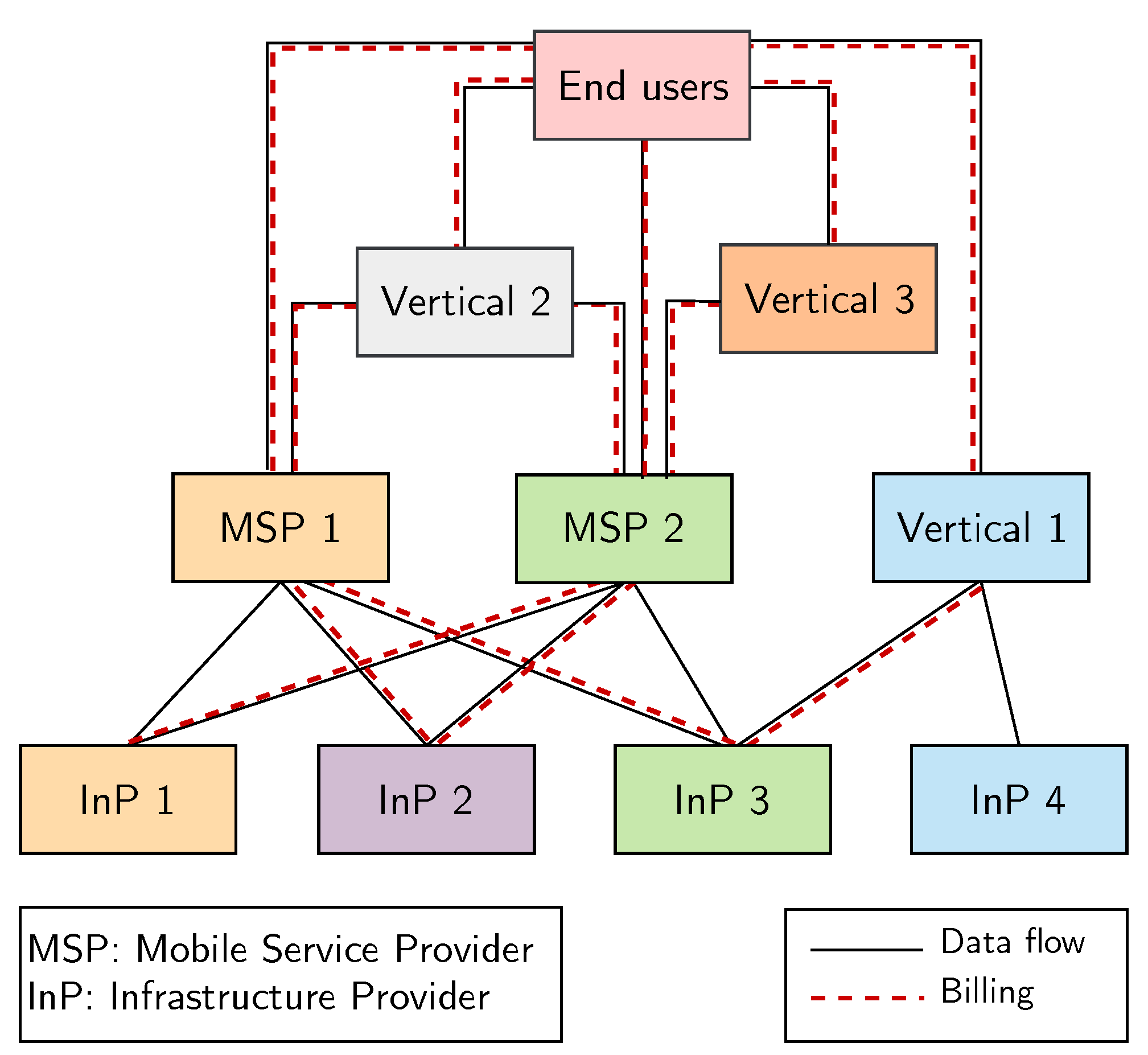
The MSP leases resources (radio, processing, storage, and networking) from one or multiple InPs. It may deploy proper infrastructure and, hence, also play the role of InP, as illustrated in Figure 1. Additionally, the MSP offers and manages network services, such as eMBB slices, to end-users. It also provides the necessary resources to carry on multi-tenancy scenarios, which are defined as the ability to provide various services to multiple tenants and pool resources from several InPs at the same time [17]. Following the tenant’s size and expertise, the latter may control the deployed NFs and tailor the slice through its management and network orchestration (MANO) functional layer. MANO requires a cross-domain orchestration framework to allow resource pooling over multiple InPs [18]. Some verticals may even play the role of MSPs and manage their own network slices, as shown in Figure 1 [7].
In [6], the authors introduce Network slicing as a service (NSaaS) Paradigm. This concept allows operators to offer customizable E2E networks as a service. Accordingly, the MSP should enable access to a catalog of network slice templates stored in a repository to its clients (whether they are end-users or tenants). The network slice template emphasizes the network slice instance structure, specifying the necessary virtual and physical NFs (VNFs and PNFs) to deploy an E2E network slice based on the constraints of the technical requirements of the desired service [17].
In summary, the MSP leases chunks of the acquired resources from the InPs to the end-users and tenants. In the same way, the tenants provide the necessary resources to grant access to end-users through slices.
2.2. Service Level Agreements
Figure 1 represents the business relationships between actors and illustrates the resource management complexity when ensuring QoS for slices. In other words, when SLAs are set up between the different actors, who is responsible for ensuring that their terms are respected? One key point is that the InP cannot accept all resource demands from MSPs, as its resources are limited. On the other hand, even if MSPs can lease resources from different InPs, they cannot admit every slice request from tenants, mainly as some slices are resource-hungry and, thus, burdensome to maintain. Keeping in mind that the InPs’ objective is to maximize the revenue and resource utilization while the MSPs aim at maximizing their revenues from tenants and minimizing their resource leasing costs, guaranteeing that QoS is not an easy task; thereby, estimating the resources is necessary to meet the slice SLAs.
Note that the negotiated SLA is valid for the slice’s entire life-cycle; it stipulates the customer-centered requirements stated in the form of key performance indicators (KPIs) like capacity, reliability, availability, latency, and coverage area. Given the rising number of customers and applications, building customizable and programmable network slices requires an SLA management framework that is automatically capable of generating SLA templates and mapping the high-level service-oriented requirement to a low-level technical description. [19] introduces a comprehensive E2E structure of a slice-based SLA between a tenant and mobile service provider while balancing the gains of both parties and also discusses the metrics to be considered during the agreement.
Specifically, many tenants do not have sufficient expertise in the telecommunications field. Hence, the MSP will have to guarantee the network slice’s performance agreed in the SLA on behalf of the tenant. In this case, the tenant has neither control nor visibility over the resources but receives performance reports to ensure that the service requirements specified in the SLA are respected. The tenant can demand some guarantees from the service provider if the latter fails to deliver the high-level metrics agreed upon in the SLA.
Concerning the relationship between the MSP and the InP, it cannot incorporate a complete SLA as the InP does not have visibility on the slice’s resources on several InPs. However, the MSP and the InP may establish a contract that stipulates the resource cost and a target acceptance ratio of resource allocation demands. The design of such agreements between MSPs and InPs, in knowing the SLAs between tenants and MSPs, is an important research topic in the slicing context.
3. RAN Resource Allocation and Traffic Steering
Before describing the slice management function placement options, we aim in this section at identifying the role of each player in the slice management and the entities that are responsible for managing traffic and resources for the slices.
3.1. Slice Management Functions Description and Ownership
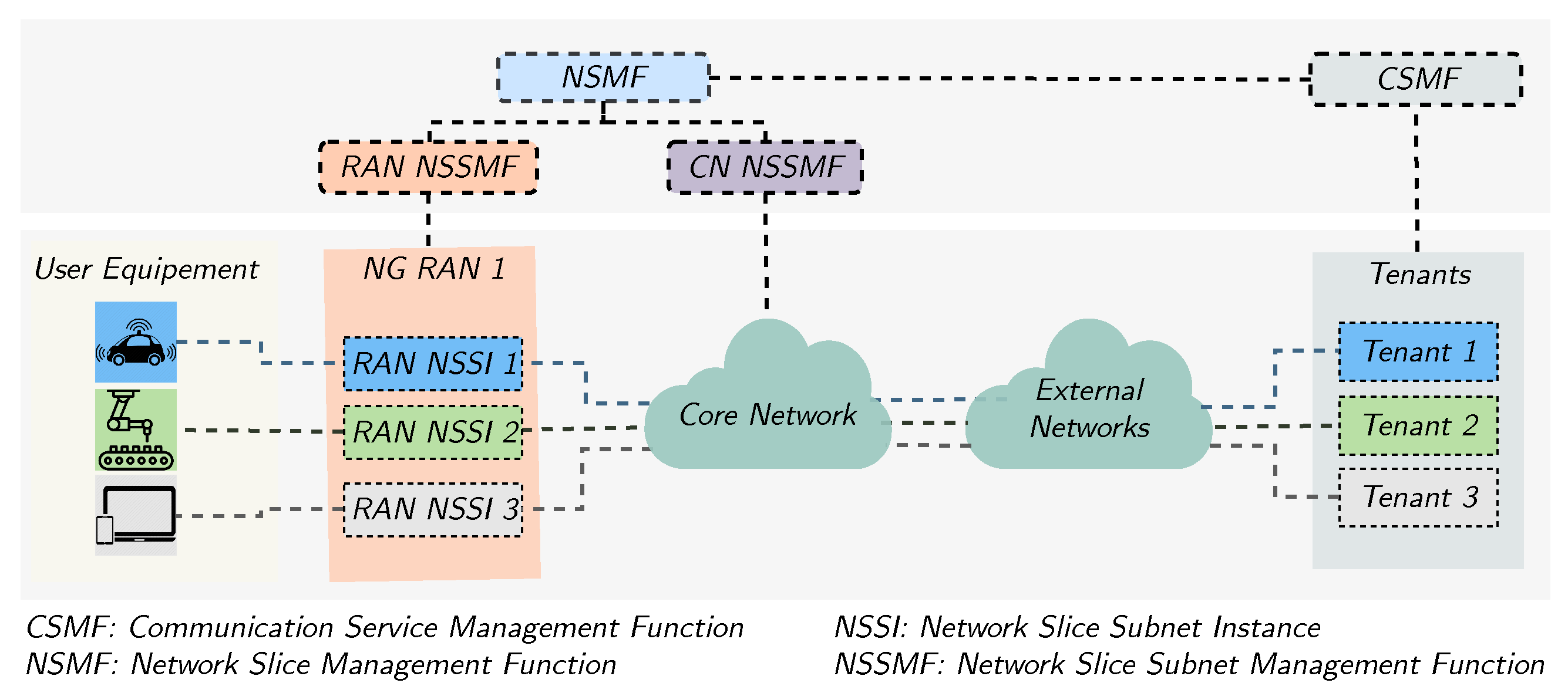
The MSP has to create and simultaneously maintain many Network Slice Instances (NSI). An NSI comprises Core Network (CN) and RAN Network Slice Subnet Instances (NSSI), which are arranged to provide the necessary resources and functionalities and, thus, deliver the tenants’ services. Each NSSI encompasses Physical Network Functions (PNFs) and Virtual Network Functions (VNFs) that are either dedicated or common among different slices. Figure 2 summarizes the infrastructure and management Layer entities in a network slicing scenario according to 3GPP [20].
For instance, the tenant’s management function, called the Communication Service Management Function (CSMF) forwards its service requirements to the Network Slice Management Function (NSMF). The NSMF translates the E2E high-level performance requirements desired by the tenant to the CN and RAN low-level requirements managed by the Network Slice Subnet Management Function (NSSMF). Thereafter, the RAN NSSMF converts the low-level requirements into RRM specific requirements and sets the resource allocation policy at the Base Station’s (BS) MAC scheduler.
In contrast, the CN NSSMF deploys and maps the service-oriented VNFs. Both the RAN and CN NSSMFs send periodic performance reports to the NSMF to verify that the service requirements are respected. For example, if the RAN NSSMF violates the network slice’s latency requirement, the NSMF can adjust the scheduling policy by reserving more resource blocks. In [21], the authors proposed a mathematical model for the NSMF management of cross-domain NSSI composing an E2E network slice using a combinatorial design. It can also alter the admission control procedure by rejecting any other network slice requests as long as the served slices’ SLAs are not respected. Table 2 summarizes these entities, their owners, and their roles in the slice resource allocation.
Note that the resource allocation task is particularly complicated in the case where several MSPs lease resources from multiple InPs. Indeed, the NSMF belongs to the MSP and has as objective to ensure that the tenant’s SLA is respected. Nevertheless, there is a RAN NSSMF that belongs to each InP, which has control over the resources of this particular InP only, as illustrated in Figure 2. In the latter, we consider three slices belonging to three different tenants. For each slice, we deploy an NSSMF per InP RAN.
3.2. Resource Allocation in the New 5G Ecosystem
Having identified the entities involved in the 5G ecosystem and their business relationships, we are now interested in detailing the MSP, tenant, and InP perspective concerning RAN resource allocation, which will allow us to design and implement resource management policies in a distributed architecture.
3.2.1. Resource Allocation from MSP Perspective
From the MSP perspective, the NSMF translates the tenant requirements into a traffic steering policy that determines to which InP(s) the packets of a specific User’s Equipment (UE) are to be forwarded. Such a policy may be generic, e.g., to privilege a particular InP when possible. Alternatively, it can be context-aware, which means examining the base station’s instantaneous load and the radio conditions with respect to the UE. For example, a potential policy is to connect a particular UE to a single InP and then split its packets between several InPs, or even duplicate them to increase reliability. Specifically, the NSMF can, for example, decide that 70% of the generated packets go through the main InP while the remaining 30% go through secondary InP during the validity time of the high-level policy.
In the case where the MSP applies the decided policy without coordination with the InPs, an entity hosted in the UE capable of implementing the NSMF scheduling strategy is required. Otherwise, the traffic steering policy can be implemented as a shared NF among multiple slices on the InP infrastructure or as a dedicated NF with some cooperation between slices to satisfy the heterogeneous optimization targets and attain effective use of the radio resources [11].
3.2.2. Resource Allocation from the Tenant Perspective
From the tenant perspective, the CSMF dynamically determines the amount of resources that need to be allocated to the slice for continuously respecting the SLA, knowing the current traffic demand. In order for these requests to be accurate, the CSMF has to rely on the information originating from the application server and/or from the end-users. The time scale for these traffic reports has to be larger than the actual scheduler time scale, i.e., in the order of tens of seconds. In the specific case where the tenant is a “big” vertical that can deploy its own infrastructure (e.g., railway and highway management companies), they have the ability to bypass the MSP and acquire the resources directly from InPs, thus, having the same behavior of MSPs as described previously.
3.2.3. Resource Allocation from the InP Perspective
From the InP perspective, the NSSMF receives the resource allocation requests from the UEs belonging to different slices and applies scheduling/admission control policies to them. The devised policies of the InP have to dynamically share the resources among the slices to raise the overall resource efficiency, especially as leasing fixed shares of resources will limit the multiplexing gains.
Note that, from an InP perspective, the authors in [22] introduced the so-called 5G network slice broker hosted in the NSSMF of the InP, which gathered the global network load measurements and configured the RAN scheduler policies based on the negotiated SLA and the size of the network slice. The openness of the mobile network may lead to adversarial behavior of MSPs consisting of maximizing the acquired share of resources. In order to deal with this issue, a ‘share-constrained proportional allocation’ mechanism is exploited in [23], and the share obtained by each tenant is determined by the equilibrium point of a network slicing game. In the same context, the authors in [24] investigated resource allocation mechanisms between tenants using game theory tools to model the non-cooperative behavior of slices. However, these works are limited to multiple tenants sharing a single InP infrastructure.
4. Impact of Placement of Intelligent Entities on Radio Resource Allocation for Slices
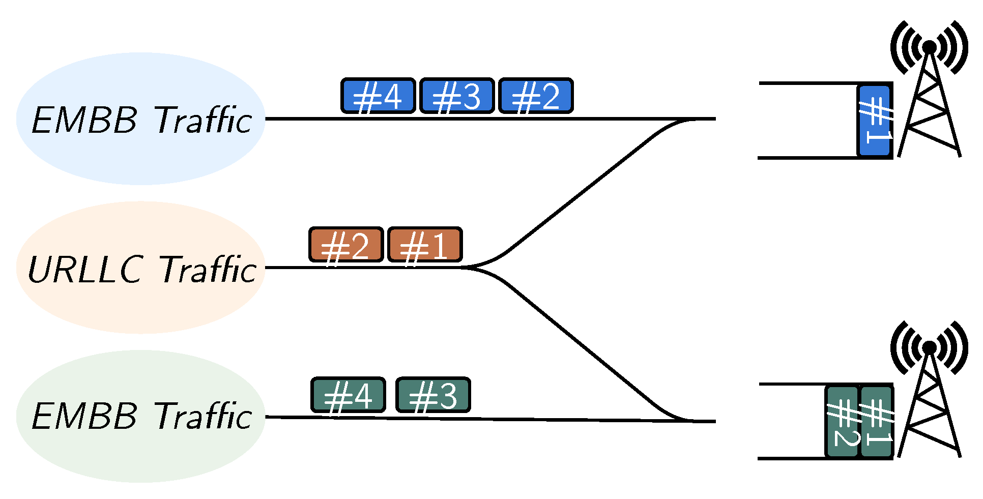
We now study the placement of entities in charge of resource allocation based on the slice management functions’ description as detailed above. We consider, for illustration, the case of a smart factory where several base stations (5G NR and/or legacy) are deployed to establish redundant coverage, which is essential for ensuring that URLLC QoS, as illustrated in Figure 3. 5G NR and 4G base stations can natively cooperate via a common core network, whereas [25] prescribes a Non-3GPP Interworking Function (N3IWF) for combining accesses using proprietary or WiFi technology. The tenant may own and manage some small cells deployed within the factory, while the InP manages base stations that operate in the sub 2 GHz spectrum for ensuring full coverage.
While some UEs will be covered by the macrocells only, it is envisioned that most locations will be covered by at least two overlapping cells, providing flexibility in resource allocation and redundancy for ensuring reliability. We, hereafter, display three potential resource allocation schemes exploiting these advantages.
4.1. Intelligence Placed at a Shared RAN NSSMF
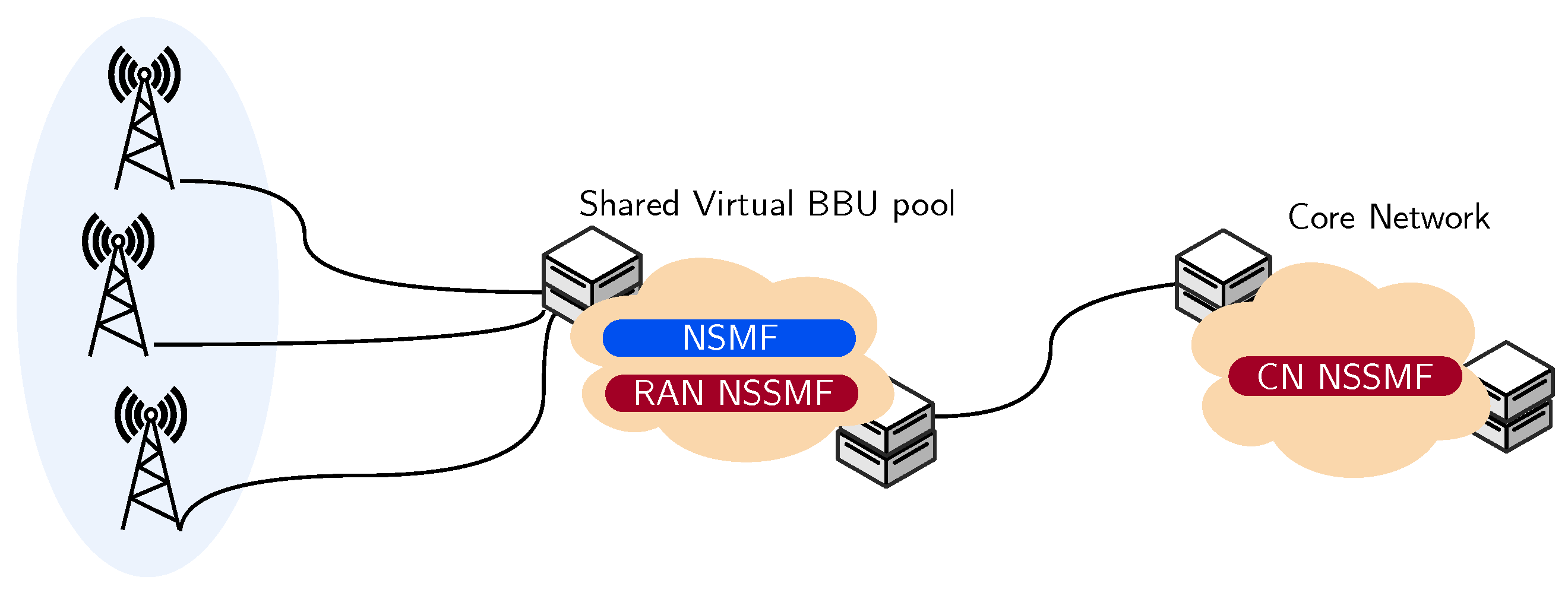
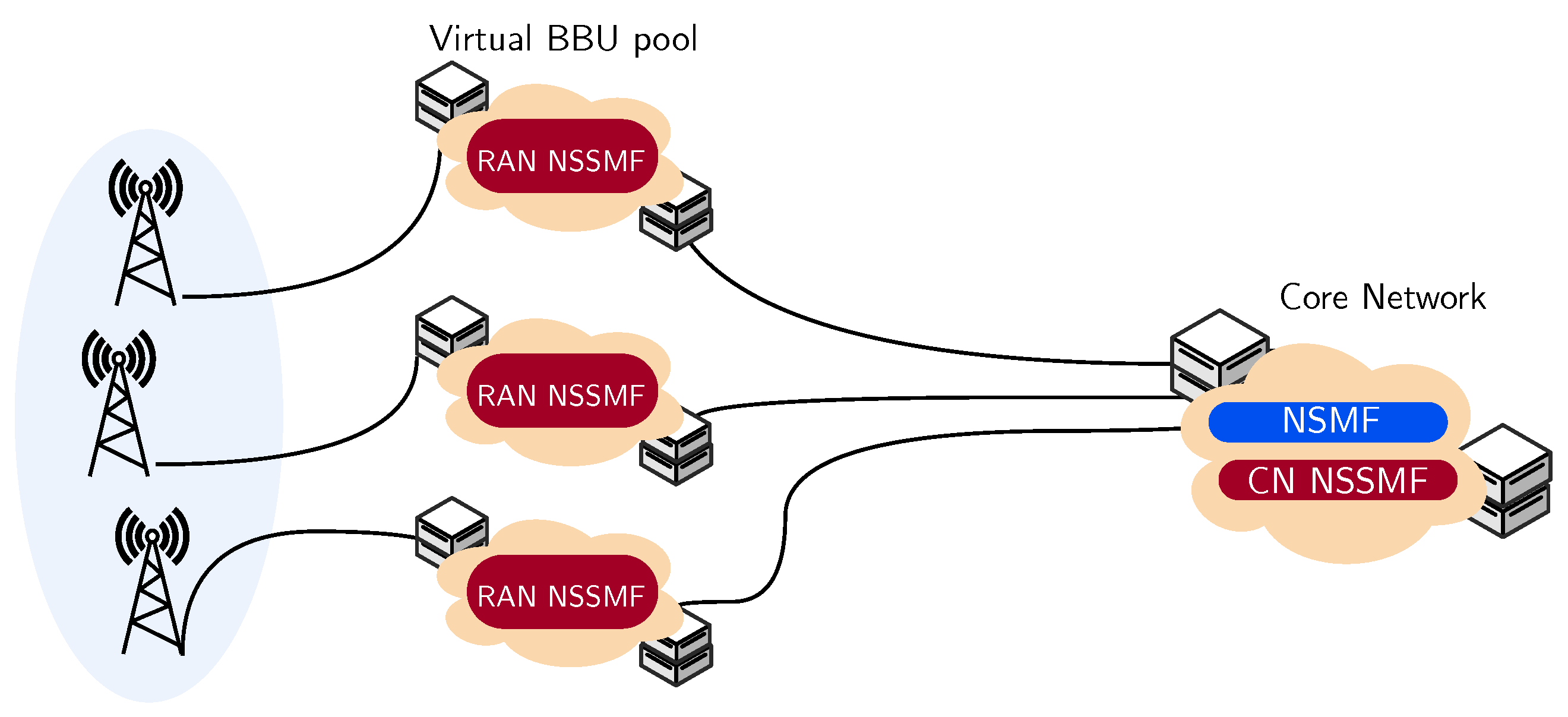
In this case, RAN slices the traffic, and the base station’s radio resources are managed via a shared RAN NSSMF with a single compound MAC scheduler. The latter has access to real-time information concerning each base station’s time-frequency matrix, thus, allowing grant-based resource allocation. This case is enabled when all base station resources are centrally managed within a common Cloud-RAN linked to the base stations by a high capacity fronthaul, as illustrated in Figure 4.
Accordingly, the NSSMF can apply a dynamic strategy to URLLC traffic, sending packets to the BS with the lowest instantaneous load to minimize the latency. Each base station is connected to a set of eMBB users. The BS manages the generated eMBB traffic by the users attached to it independently of the instantaneous load, whereas the URLLC traffic is managed jointly with the other base station, as illustrated in Figure 3.
The NSSMF can apply this strategy in both uplink and downlink. It is straightforward in the downlink where the application server sends the URLLC packets to the NSSMF, which steers them to the adequate base station for transmission. However, the UE transmits a scheduling request to NSSMF that issues a scheduling grant on one base station for the uplink. Consequently, the uplink case is more challenging as the control process mentioned above introduces a lag between the moment the NSSMF observes the traffic loads and when the scheduling grant is issued for the URLLC user.
4.2. Intelligence Placed at the NSMF
When there is restricted coordination between the InPs, and between the MSP and the InPs, as in the case where each base station has its own Baseband Units (BBU), loosely linked to other BBUs, performing dynamic steering of packets based on each cell’s instantaneous load is difficult to achieve. This is illustrated in Figure 5. In this case, a long-term policy (i.e., based on a time granularity of tens of seconds) is implemented, managed by the NSMF located somewhere at the core network level.
For this policy to be effective, the UEs (in the uplink) and the application server (in the downlink) have to apply the policy provided by the NSMF on a packet basis but without additional information on the instantaneous load of each cell. When the decision about the packet’s destination is taken, the remainder of the scheduling process is performed classically, and the RAN NSSMF does not need to know about the slice policy. We consider hereafter two feasible policies for URLLC:
- Long-term traffic steering with no redundancy: This entails a proportional division of the URLLC traffic, based on the base stations’ average capacities as estimated by the NSMF or as provided to the MSP by the RAN NSSMF of each InP.
- Long-term traffic steering with redundancy: In the absence of any information about the different base stations’ capacities, redundancy is a costly yet simple strategy that can be used to ensure reliability. This policy consists of systematically sending the arriving URLLC packets to both base stations. While packet redundancy can achieve high reliability as it enables the experience of minimum queuing latency between the BSs, it leads to the under-utilization of radio resources. The NSMF broadcasts the policy to the URLLC user equipment during the slice instantiation.
5. Performance Evaluation
In this section, we simulate the system presented in Figure 3 in three different scenarios. First, we examine the system with only URLLC packets through a resource reservation scenario for URLLC slices. Then, we consider the case where eMBB and URLLC slices share the same resources in two separate settings. We aim to gather quantitative and qualitative insights on architectural consideration’s impact on delivering the stringent latency requirements of URLLC services.
5.1. System Model
We consider a wireless system with a set of URLLC and eMBB users located within a smart factory served by two RATs with the bandwidths and . URLLC packets are steered with regard to the network architecture and the placement of the resource management entities (see Figure 4 and Figure 5). Driven by the 5G NR air interface’s flexibility, URLLC packets are served on a mini-slot basis of 2 OFDM symbols, whereas eMBB packets are served on a legacy 1 ms TTI [26]. The service times of URLLC and eMBB packets depend on the used modulation and coding scheme. The latter differs from one user to another, depending on the average radio conditions.
We model the network architecture by two parallel queues fed by a Poisson process of URLLC packets of size W with a mean arrival rate per user denoted as . Due to heterogeneous radio conditions, the Modulation and Coding Schemes (MCS) of users are different. Let be the set of spectral efficiencies associated with the different MCS, and let be the probability of having the spectral efficiency . The service time of the i-th URLLC packet at BS j is where
and is the efficiency of the MCS used by packet i on base stations j.
When URLLC and eMBB slices share the same resources, we assume each BS serves a set of eMBB users separately. Two independent Poisson processes generate eMBB packets of size with the arrival rates and . Hence, the service time of eMBB packet k at BS j is where
where is the spectral efficiency for eMBB packet k on base station j. We denote by the eMBB traffic load at BS j, defined as
where is the average service time for eMBB packets at base station j.
We study three different policies based on the architectural options discussed above:
- The decision in a shared RAN NSSMF: When the scheduling decision is taken at the RAN NSSMF level, the packet steering policy depends on the base station load. This scheme consists of sending the incoming URLLC packet to the queue with the smallest number of waiting packets. We consider two practical variants. The first assumes that the NSSMF knows the instantaneous load with a minimal control plane delay, set to 100 μs. The second case takes into account the control plane signaling delay equal to 1 ms in the numerical application. In other terms, the NSSMF relies on information reports sent by the BSs some time ago to make its decision.
- The decision in a far NSMF: When the instantaneous load is not available as the decision is taken at the NSMF level, we consider two possible resource allocation schemes.
- Redundancy: Each incoming packet is independently duplicated in both queues to experience minimal queuing delay at the interface with the lowest load. This scheme does not require any prior knowledge of the radio access channel. Therefore, it does not entail substantial control plane information.
- Without redundancy: This corresponds to a probabilistic routing of URLLC packets based on a long-term policy sent by the NSMF. We implement an NSMF proportional traffic steering based on the bandwidth, which means that p of the traffic is sent over BS1 and over BS2, where
In the following, we evaluate the outage probability of URLLC traffic originating from the above allocation schemes using Monte Carlo simulations. The outage probability is defined as the probability that the packet latency exceeds a predefined delay budget set to ms. We study three distinct scenarios, each in two separate settings: the homogeneous case (i.e., ) and the heterogeneous case with dissimilar bandwidth at the BSs. Table 3 summarizes the system setting for performance evaluation.
5.2. Bandwidth Reservation Case for an URLLC Slice
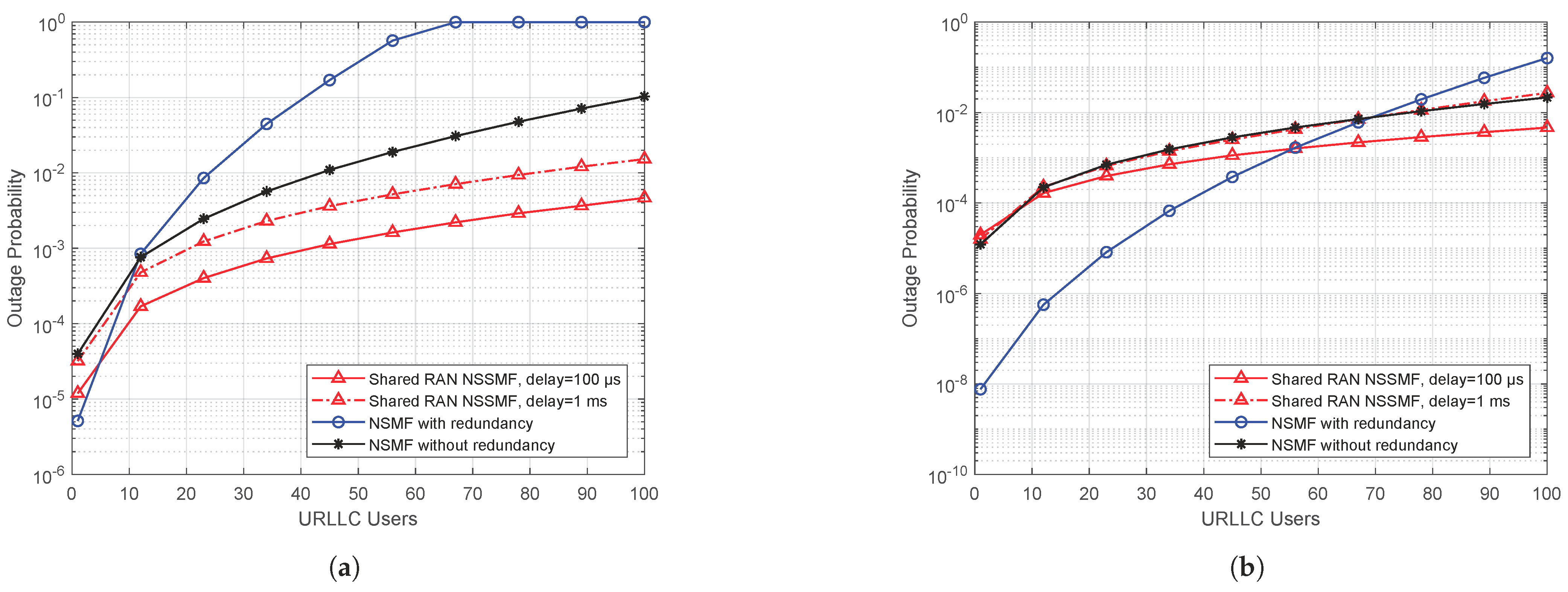
First, we study the impact of slicing architecture on URLLC traffic. In this scenario, we reserve a sub-band for URLLC traffic on each base station to achieve hard isolation with the eMBB traffic. We examine the homogeneous and the heterogeneous setting where we assume a reserved bandwidth of MHz and MHz, respectively. The URLLC packet mean arrival rate per user is set to packets/s. Figure 6 shows the URLLC traffic’s outage probability stemming from the different policies while increasing the number of URLLC users in the smart factory.
We observed two regimes through a comprehensive look at the proposed allocation schemes’ performance, with each giving an advantage for one of the architectural options. Figure 6a shows that the redundancy displays the best performance for a restricted number of URLLC users in the homogeneous case. In the medium to high load regimes, placing the intelligence at a shared RAN NSSMF with reduced control delay has an advantage over the far NSMF entity’s management. A large control delay worsens the performance of the shared RAN NSSMF policy. Note that the NSMF proportional traffic steering policy outperformed the redundancy scheme in high load regimes since it circumvented overloading. However, high load regimes are not suitable for meeting the URLLC QoS requirements, where a very low outage probability is sought, on the order of to .
In the heterogeneous case (see Figure 6b), we notice that the redundancy policy profits from the asymmetric reserved bandwidth at the BSs compared to the previous case. This can be explained by the fact that duplicated URLLC packets undergo almost the same service time. Consequently, the minimum sojourn time at the system is not significantly reduced. Thus, only packet duplication can achieve the target QoS in this low load regime without the need for exhaustive cooperation.
5.3. The Coexistence of eMBB and URLLC Slices
We now move to a setting where URLLC and eMBB slices share the same resources. We exploit the overall bandwidth without reserving a fixed band for URLLC traffic. Again, we study the homogeneous and the heterogeneous case where the overall bandwidths are MHz and MHz, respectively. Our objective is twofold. First, we aim to study the impact of eMBB and URLLC multiplexing on the URLLC performance, and second, we aim at reinspecting the role of URLLC slice management function placement.
5.3.1. Variable URLLC Traffic with Fixed eMBB Traffic
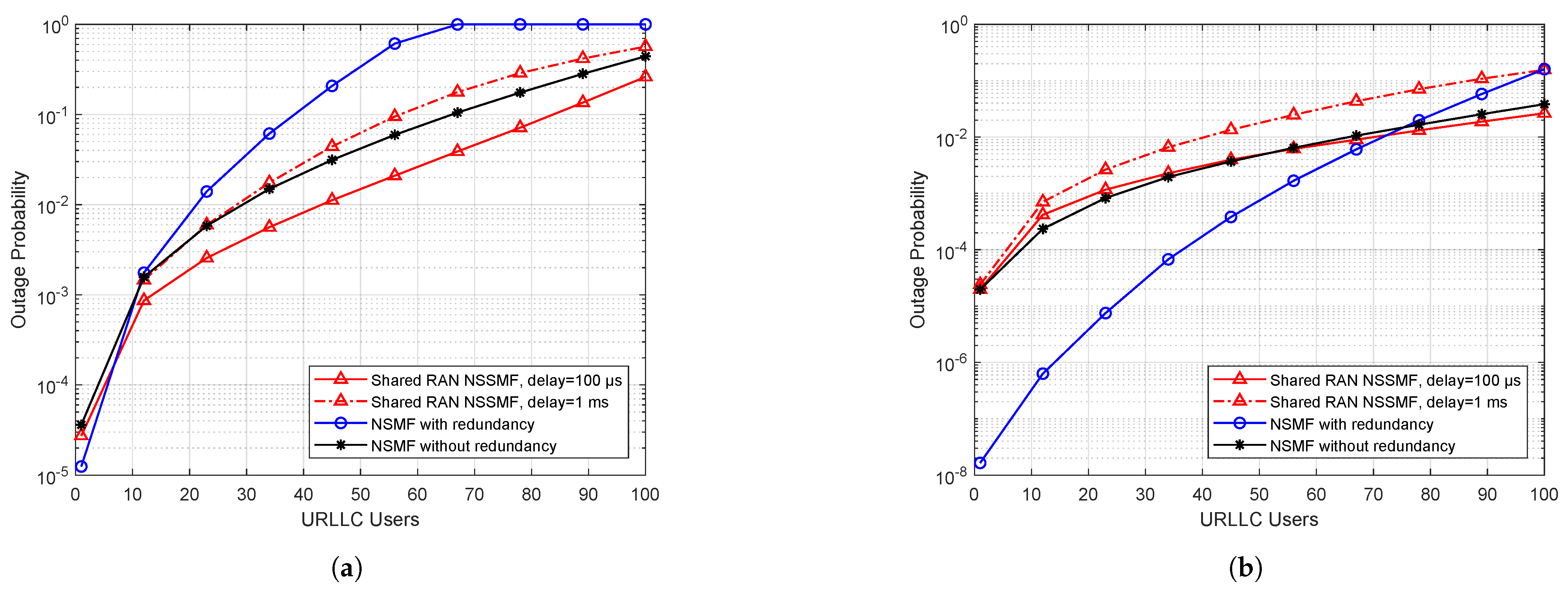
To obtain insights on the impact of coexistence between eMBB and URLLC traffic, we gradually increase the URLLC users’ number while maintaining the eMBB load at each BS at . As with the previous case, we set the URLLC packet mean arrival rate per user to packets/s. In Figure 7, we plot the outage probability for URLLC packets. We first remark that the outage probability has higher values than the previous case (separated URLLC/eMBB) since the URLLC packets compete for radio resources with large eMBB packets. Ultra-reliability is, thus, very difficult to achieve when there is no strict resource reservation for URLLC traffic.
We now take a deeper look at the performance of the different URLLC slice management policies. Figure 7a shows that the NSMF redundancy degraded mid to high load performance but was essential for achieving high reliability. Indeed, even if it increased the load, redundancy increased the chance that duplicated packets had access to the queue with minimal awaiting eMBB packets, thus, reducing the URLLC packet sojourn time. However, tight coordination at the RAN NSSMF level offered good results but was still outperformed in low load regimes by packet duplication. Therefore, it is recommended to design a dynamic strategy where we move from an NSMF redundancy to a shared NSSMF policy based on the number of URLLC users in the factory.
Figure 7b shows the outage probability in the heterogeneous configuration. The performance trend is similar to that of the homogeneous counterpart. The difference is that we need not change our policy dynamically since the NSMF redundancy policy outperformed the other policies for all traffic load regimes. In both configurations, the NSMF proportional policy offers the worst performance because it is a long-term strategy that does not consider traffic evolution over time.
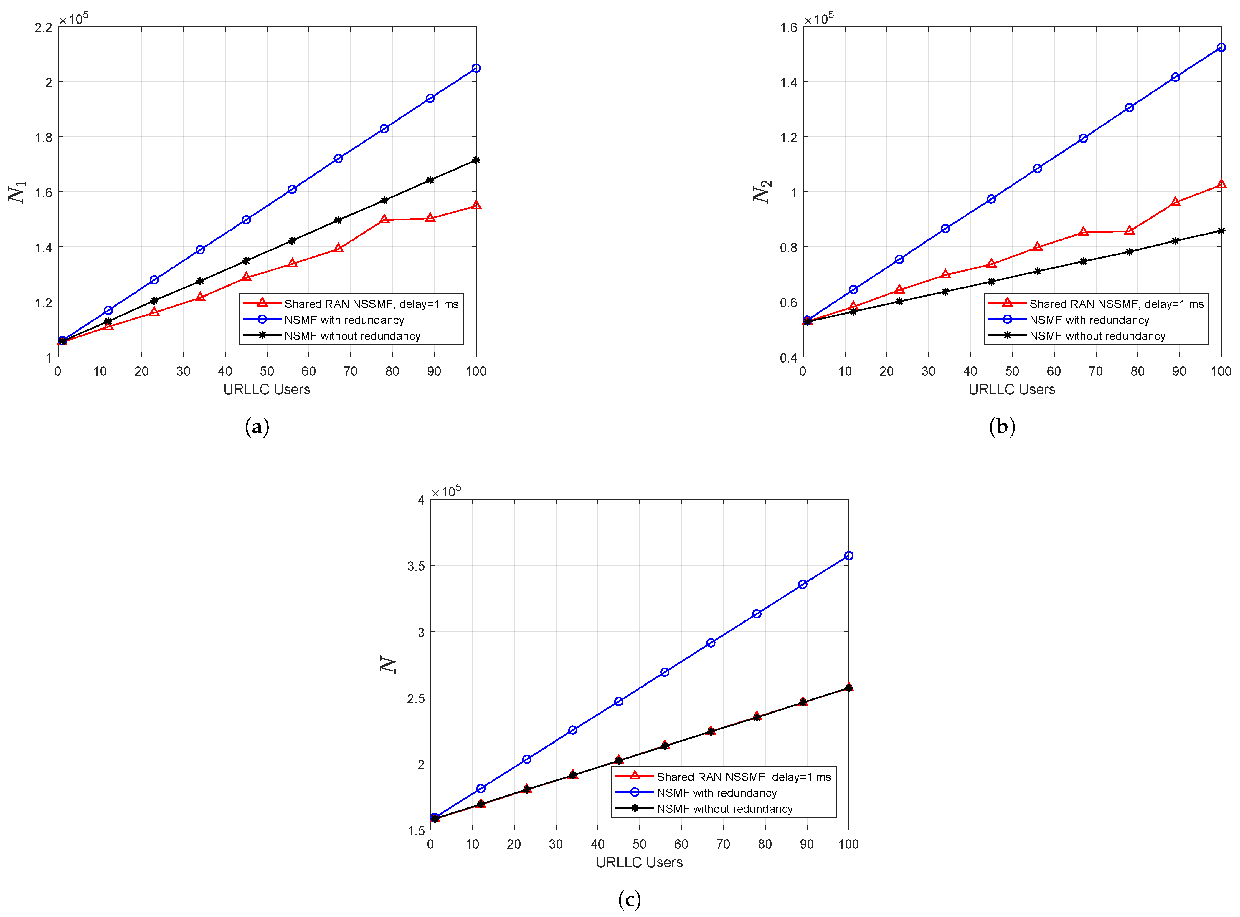
We denote by , , and N the number of packets served in BS1, BS2, and the overall system (i.e., the sum of packets served in BS 1 and 2). Applying the redundancy-based scheme in both the uplink and the downlink instigates an over-utilization of resources that we quantify in Figure 8. Hence, we can see that respecting the latency requirement of URLLC use cases degrades the eMBB users’ rates. This degradation can also be caused by scheduling URLLC packets over mini-slot while puncturing eMBB transmissions [9].
5.3.2. Variable eMBB Traffic with Fixed URLLC Traffic
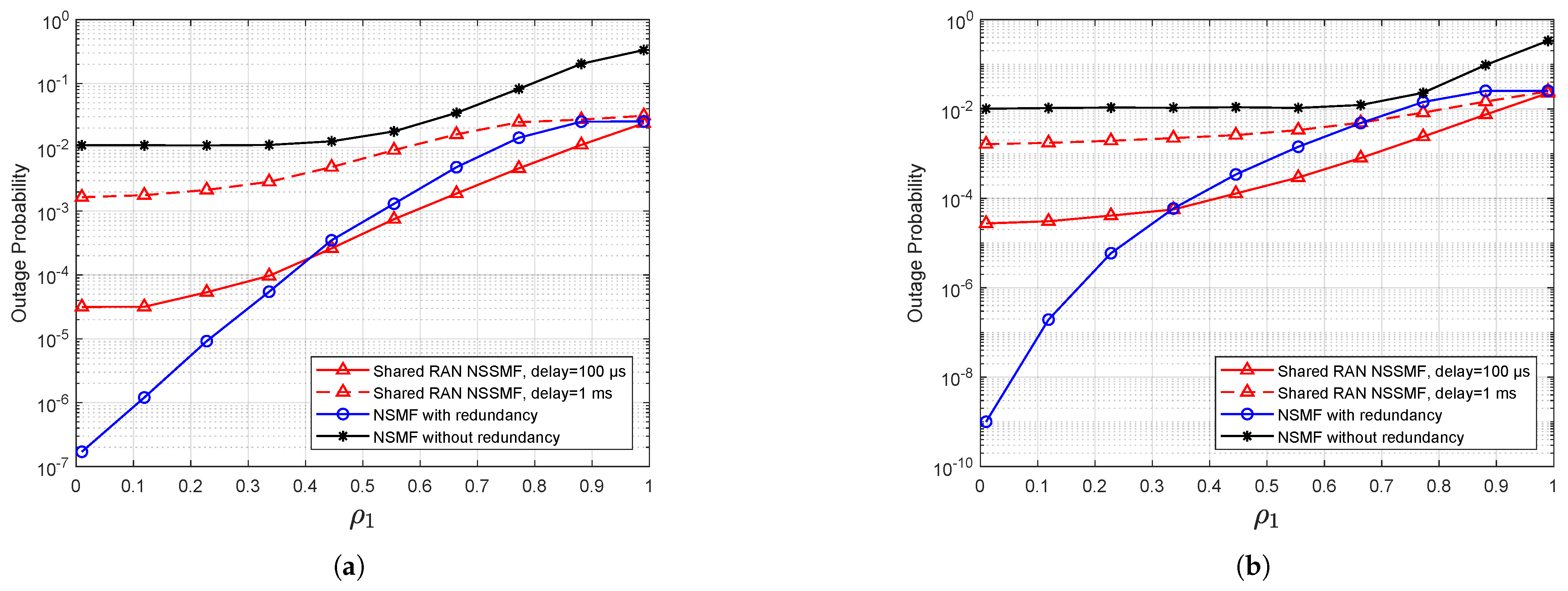
We investigate another setting where we have a fixed number of URLLC users set to 100. The URLLC packet mean arrival rate per user is set to packets/s. We vary the eMBB load at one BS while maintaining the traffic load with at the other.
We first note that the outage probability for the heterogeneous configuration shows a similar performance trend to the homogeneous case. For instance, the NSMF redundancy policy presents a lower outage probability compared to the other scheduling policies, up to BS1 load and , for the homogeneous and the heterogeneous case, respectively (see Figure 9a,b). These values represent a threshold for designing a dynamic strategy, where we change the scheduling from the NSMF redundancy to the shared NSSMF. Again, the NSMF proportional policy represents the worst performance, and the control plane signalization degrades the shared NSMF performance.
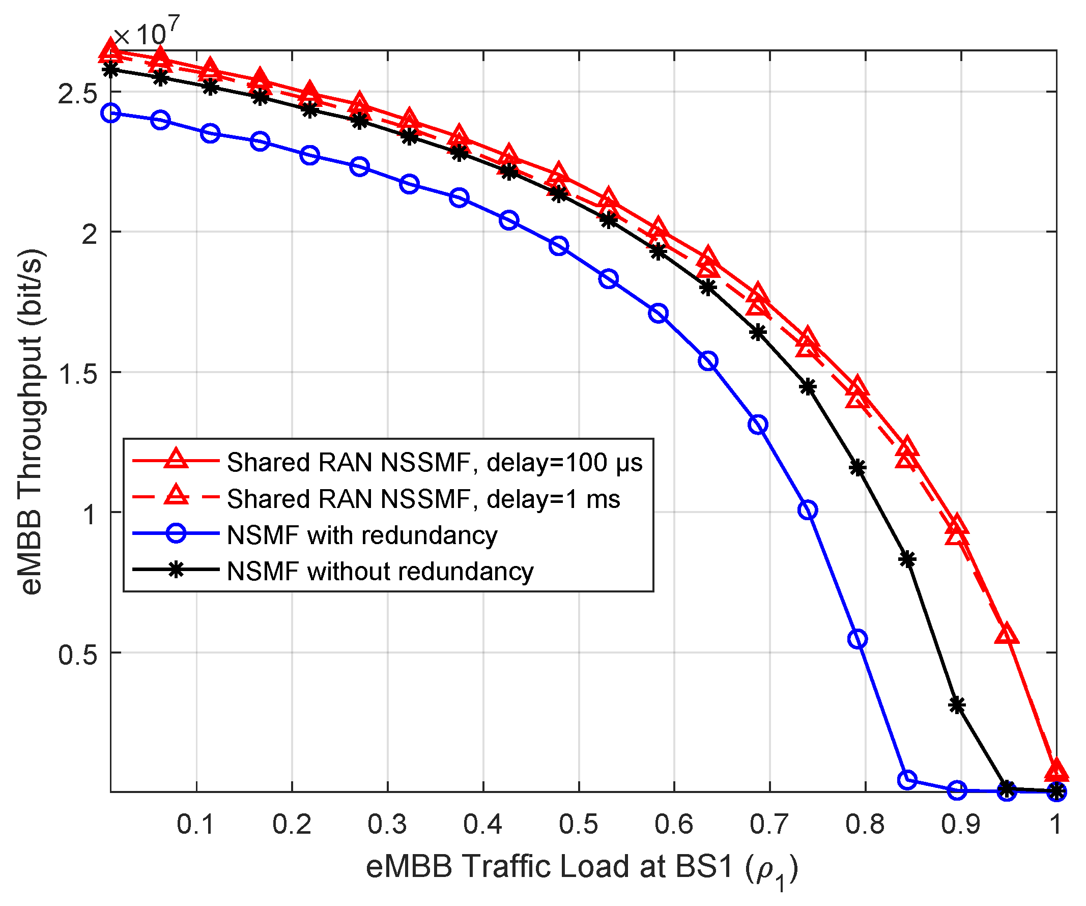
Figure 10 shows the eMBB throughput as a function of the eMBB traffic load at BS1. Our goal is to quantify the impact of the scheduling policies on the performance of eMBB services. We can see that, although redundancy is vital to achieving the URLLC requirements in terms of low outage probabilities, as shown above, it leads to the degradation of the eMBB throughput due to the inefficient use of resources. To summarize, when the slice scheduling functions are placed far from the base stations, introducing a delayed decision, the stringent delay requirements of URLLC cannot be achieved with a per-packet scheduling policy, and a systematic redundancy is needed, leading to inefficiencies in resource usage.
5.4. Case Study: A Smart Factory Served by Three BSs
We corroborate the results shown in Section 5.2 by simulating the case where three BSs are co-located and serve a set of URLLC users. We denote by the reserved bandwidth at BS3. Likewise, we reserve a sub-band for URLLC traffic on each base station set MHz for the homogeneous case, and MHz for the heterogeneous case.
Figure 11 displays the URLLC traffic’s outage probability originating from the different policies while raising the number of URLLC users in the smart factory. Similar observations to the two base station case can be made. In particular, the shared RAN NSSMF case, as it manages load instantaneously, outperformed the NSMF case. However, this advantage vanished when the delay increased. On the other hand, the systematic redundancy case outperformed the remaining schemes for low load; however, its performance degraded for the high load regime. The same tendency was observed for the heterogeneous case. The difference is that the amount of resources was more significant, leading to a switch toward the high load regime.
6. Concluding Remarks
In this paper, we explored the network slicing architecture impact on the URLLC performance in the multi-connectivity case. We first identified the different RAN resource allocation actors while shedding light on their business relationships and their ownership of the slice management functions. Depending on this ecosystem description, we studied various options for the placement of the management entities involved in resource allocation and traffic steering decisions while focusing on the challenging use case of URLLC traffic. In particular, we studied two architectural options; the first with loose coupling, where the scheduling policy was determined within the NSMF by the vertical. The second case used tight coupling where the scheduling decision was taken at the NSSMF level by the mobile network operator who owns the different base stations.
Our results show that, while a tight coupling was beneficial for the system when the carriers were both URLLC and eMBB users, it lost its efficiency rapidly when information about each cell’s load arrived with a delay, sometimes leading to an outdated scheduling decision. This effect arose when the slice scheduling functions were placed far from the base stations, introducing a control plane delay. For a low URLLC load regime, systematic redundancy, which does not require any tight coupling between base stations, was crucial to achieving a low outage probability.
Several possible extensions can be envisaged to respect the stringent reliability and latency requirement of URLLC use cases. For instance, we aim to apply our study to other forms of redundancy, e.g., time and frequency packet replication, in addition to the spatial packet duplication considered in this paper, and to explore the feasibility and effectiveness of these schemes for different slicing architectural options. Another idea is to investigate exploiting the presence of more than two base stations.
Author Contributions
Conceptualization, A.C., S.E.E. and A.M.M.; methodology, A.C., S.E.E. and A.M.M.; software, A.C.; validation, A.C., S.E.E. and A.M.M.; formal analysis, A.C., S.E.E. and A.M.M.; investigation, A.C.; writing—original draft preparation, A.C.; writing—review and editing, S.E.E. and A.M.M.; visualization, A.C.; supervision, S.E.E. and A.M.M.; project administration, S.E.E. and A.M.M.; funding acquisition, S.E.E. and A.M.M. All authors have read and agreed to the published version of the manuscript.
Funding
This work is supported by MAESTRO-5G project funded by the French Agence Nationale de la Recherche (ref. ANR-18-CE25-0012).
Institutional Review Board Statement
Not applicable.
Informed Consent Statement
Not applicable.
Conflicts of Interest
The authors declare no conflict of interest.
References
- Chen, H.; Abbas, R.; Cheng, P.; Shirvanimoghaddam, M.; Hardjawana, W.; Bao, W.; Li, Y.; Vucetic, B. Ultra-Reliable Low Latency Cellular Networks: Use Cases, Challenges and Approaches. IEEE Commun. Mag. 2018, 56, 119–125. [Google Scholar] [CrossRef] [Green Version]
- 3GPP. Study on Communication for Automation in Vertical Domains; 3GPP TR 22.804 v16.3.0, Technical Report; 3rd Generation Partnership Project (3GPP); University of Nice Sophia Antipolis: Nice, France, 2020. [Google Scholar]
- NGMN. 5G E2E Technology to Support Verticals URLLC Requirements; NGMN Alliance: Frankfurt, Germany, 2019. [Google Scholar]
- Foukas, X.; Patounas, G.; Elmokashfi, A.; Marina, M.K. Network slicing in 5G: Survey and challenges. IEEE Commun. Mag. 2017, 55, 94–100. [Google Scholar] [CrossRef] [Green Version]
- Rost, P.; Mannweiler, C.; Michalopoulos, D.S.; Sartori, C.; Sciancalepore, V.; Sastry, N.; Holland, O.; Tayade, S.; Han, B.; Bega, D.; et al. Network slicing to enable scalability and flexibility in 5G mobile networks. IEEE Commun. Mag. 2017, 55, 72–79. [Google Scholar] [CrossRef] [Green Version]
- Zhou, X.; Li, R.; Chen, T.; Zhang, H. Network slicing as a service: Enabling enterprises’ own software-defined cellular networks. IEEE Commun. Mag. 2016, 54, 146–153. [Google Scholar] [CrossRef]
- Ordonez-Lucena, J.; Ameigeiras, P.; Lopez, D.; Ramos-Munoz, J.J.; Lorca, J.; Folgueira, J. Network slicing for 5G with SDN/NFV: Concepts, architectures, and challenges. IEEE Commun. Mag. 2017, 55, 80–87. [Google Scholar] [CrossRef] [Green Version]
- 3GPP. Summary of Rel-15 Work Items; 3GPP TR 21.915 v15.0.0, Technical Report; 3rd Generation Partnership Project (3GPP); University of Nice Sophia Antipolis: Nice, France, 2019. [Google Scholar]
- Elayoubi, S.E.; Jemaa, S.B.; Altman, Z.; Galindo-Serrano, A. 5G RAN Slicing for Verticals: Enablers and Challenges. IEEE Commun. Mag. 2019, 57, 28–34. [Google Scholar] [CrossRef] [Green Version]
- Sallent, O.; Perez-Romero, J.; Ferrus, R.; Agusti, R. On radio access network slicing from a radio resource management perspective. IEEE Wirel. Commun. 2017, 24, 166–174. [Google Scholar] [CrossRef]
- Ferrus, R.; Sallent, O.; Perez-Romero, J.; Agusti, R. On 5G radio access network slicing: Radio interface protocol features and configuration. IEEE Commun. Mag. 2018, 56, 184–192. [Google Scholar] [CrossRef]
- Elayoubi, S.E.; Brown, P.; Deghel, M.; Galindo-Serrano, A. Radio Resource Allocation and Retransmission Schemes for URLLC Over 5G Networks. IEEE J. Sel. Areas Commun. 2019, 37, 896–904. [Google Scholar] [CrossRef] [Green Version]
- Pijnappel, T.R.; Borst, S.C.; Whiting, P.A. Joint Scheduling of Low-Latency and Best-Effort Flows in 5G Wireless Networks. In Proceedings of the 2020 18th International Symposium on Modeling and Optimization in Mobile, Ad Hoc, and Wireless Networks (WiOPT), Volos, Greece, 15–19 June 2020; pp. 1–8. [Google Scholar]
- Chagdali, A.; Elayoubi, S.E.; Masucci, A.M.; Simonian, A. Performance of URLLC Traffic Scheduling Policies with Redundancy. In Proceedings of the 2020 32nd International Teletraffic Congress (ITC 32), Osaka, Japan, 22–24 September 2020; pp. 55–63. [Google Scholar] [CrossRef]
- Chagdali, A.; Elayoubi, S.E.; Masucci, A.M. Impact of Slice Function Placement on the Performance of URLLC with Redundant Coverage. In Proceedings of the 2020 16th International Conference on Wireless and Mobile Computing, Networking and Communications (WiMob), Thessaloniki, Greece, 12–14 October 2020; pp. 1–6. [Google Scholar] [CrossRef]
- Pujol, F.; Elayoubi, S.E.; Markendahl, J.; Salahaldin, L. Mobile telecommunications ecosystem evolutions with 5G. Commun. Strateg. 2016, 102, 109–130. [Google Scholar]
- View on 5G Architecture (Version 2.0); 5G PPP Architecture Working Group; European Commission: Brussels, Belgium, 2017.
- Francescon, A.; Baggio, G.; Fedrizzi, R.; Ferrusy, R.; Ben Yahiaz, I.G.; Riggio, R. X–MANO: Cross–domain management and orchestration of network services. In Proceedings of the 2017 IEEE Conference on Network Softwarization (NetSoft), Bologna, Italy, 3–7 July 2017; pp. 1–5. [Google Scholar] [CrossRef]
- Habibi, M.A.; Han, B.; Nasimi, M.; Schotten, H.D. The structure of service level agreement of slice-based 5G network. arXiv 2018, arXiv:1806.10426. [Google Scholar]
- 3GPP. Technical Specification Group Services and System Aspects; Management and Orchestration; Provisioning; 3GPP TS 28.531 v16.9.0, Techical Spec.; 3rd Generation Partnership Project (3GPP); University of Nice Sophia Antipolis: Nice, France, 2021. [Google Scholar]
- Gligoroski, D.; Kralevska, K. Expanded Combinatorial Designs as Tool to Model Network Slicing in 5G. IEEE Access 2019, 7, 54879–54887. [Google Scholar] [CrossRef]
- Samdanis, K.; Costa-Perez, X.; Sciancalepore, V. From network sharing to multi-tenancy: The 5G network slice broker. IEEE Commun. Mag. 2016, 54, 32–39. [Google Scholar] [CrossRef]
- Caballero, P.; Banchs, A.; De Veciana, G.; Costa-Perez, X. Network Slicing Games: Enabling Customization in Multi-Tenant Mobile Networks. IEEE/ACM Trans. Netw. 2019, 27, 662–675. [Google Scholar] [CrossRef]
- Caballero, P.; Banchs, A.; De Veciana, G.; Costa-Pérez, X.; Azcorra, A. Network slicing for guaranteed rate services: Admission control and resource allocation games. IEEE Trans. Wirel. Commun. 2018, 17, 6419–6432. [Google Scholar] [CrossRef] [Green Version]
- 3GPP. Access to the 3GPP 5G Core Network (5GCN) via Non-3GPP Access Networks (N3AN); 3GPP TS 24.502 V16.2.0, Tech. Spec.; 3rd Generation Partnership Project (3GPP); University of Nice Sophia Antipolis: Nice, France, 2019. [Google Scholar]
- Ji, H.; Park, S.; Yeo, J.; Kim, Y.; Lee, J.; Shim, B. Ultra-reliable and low-latency communications in 5G downlink: Physical layer aspects. IEEE Wirel. Commun. 2018, 25, 124–130. [Google Scholar] [CrossRef] [Green Version]
- ITU-R. Minimum Requirements Related to Technical Performance for IMT-2020 Radio Interface(s); Technical Report; International Telecommunication Union: Geneva, Switzerland, 2017. [Google Scholar]
Figure 1.
Business relationships in the 5G RAN. Solid lines correspond to data flow, while dashed lines correspond to money flow. MSPs have billing relationships with InPs except when the InP is owned by the MSP.
Figure 1.
Business relationships in the 5G RAN. Solid lines correspond to data flow, while dashed lines correspond to money flow. MSPs have billing relationships with InPs except when the InP is owned by the MSP.

Figure 2.
Overview of the infrastructure and management layer in a network slicing scenario.

Figure 3.
Traffic steering in the industry 4.0 use case. Two base stations in the neighborhood of URLLC user equipment.
Figure 3.
Traffic steering in the industry 4.0 use case. Two base stations in the neighborhood of URLLC user equipment.

Figure 4.
The distribution of management functions in a factory scenario. Intelligence placed at the level of a shared RAN NSSMF.
Figure 4.
The distribution of management functions in a factory scenario. Intelligence placed at the level of a shared RAN NSSMF.

Figure 5.
The distribution of management functions in a factory scenario. Intelligence placed at the NSMF level.
Figure 5.
The distribution of management functions in a factory scenario. Intelligence placed at the NSMF level.

Figure 6.
The outage probability in the case of bandwidth reservation for URLLC packets. (a) MHz; and (b) MHz.
Figure 6.
The outage probability in the case of bandwidth reservation for URLLC packets. (a) MHz; and (b) MHz.

Figure 7.
Outage probability in the case of fixed eMBB and variable URLLC traffic without bandwidth reservations. (a) MHz; and (b) MHz.
Figure 7.
Outage probability in the case of fixed eMBB and variable URLLC traffic without bandwidth reservations. (a) MHz; and (b) MHz.

Figure 8.
The number of packets served in BS1, BS2, and the system, with MHz. (a) BS1; (b) BS2; and (c) System.
Figure 8.
The number of packets served in BS1, BS2, and the system, with MHz. (a) BS1; (b) BS2; and (c) System.

Figure 9.
The outage probability in the case of variable eMBB at BS1, fixed eMBB traffic at BS2, and a fixed number of URLLC users. (a) MHz; and (b) MHz.
Figure 9.
The outage probability in the case of variable eMBB at BS1, fixed eMBB traffic at BS2, and a fixed number of URLLC users. (a) MHz; and (b) MHz.

Figure 10.
The eMBB throughput in the case of variable eMBB traffic at BS1, fixed eMBB traffic at BS2, and a fixed number of URLLC users, where MHz.
Figure 10.
The eMBB throughput in the case of variable eMBB traffic at BS1, fixed eMBB traffic at BS2, and a fixed number of URLLC users, where MHz.

Figure 11.
The outage probability in the case of bandwidth reservation for URLLC packets. (a) MHz; and (b) MHz.
Figure 11.
The outage probability in the case of bandwidth reservation for URLLC packets. (a) MHz; and (b) MHz.


Table 1.
List of used abbreviations.
| Acronym | Definition |
|---|---|
| 3GPP | Third Generation Partnership Project |
| 5G | Fifth generation of wireless networks |
| BBU | Baseband Units |
| BS | Base Station |
| CN | Core Network |
| CSMF | Communication Service Management Function |
| eMBB | Enhanced Mobile Broadband |
| InP | Infrastructure Provider |
| KPI | Key Performance Indicator |
| MANO | Management and Network Orchestration |
| MCS | Modulation and Coding Schemes |
| MSP | Mobile Service Provider |
| MVNO | Mobile Virtual Network Operator |
| NF | Network Function |
| NFV | Network Function Virtualization |
| NR | New Radio |
| NSaaS | Network Slicing as a Service |
| NSI | Network Slice Instance |
| NSMF | Network Slice Management Function |
| NSSI | Network Slice Subnet Instance |
| NSSMF | Network Slice Subnet Management Function |
| OTT | Over-The-Top |
| PNF | Physical Network Function |
| PNF | Physical Network Function |
| QoS | Quality of Service |
| RAN | Radio Access Network |
| RAT | Radio Access Technology |
| RRM | Radio Resource Management |
| SDN | Software-Defined Network |
| SLA | Service Level Agreement |
| UE | User Equipment |
| URLLC | Ultra-reliable and Low-Latency Communications |
| VNF | Virtual Network Function |
Table 2.
Entities involved in RAN resource allocation and their roles.
| Function | Location | Functionality | Owner | Autonomy |
|---|---|---|---|---|
| UE scheduler | UE | Dispatches UE traffic to access points | Vertical | Applies policies specified by the vertical |
| BS scheduler | Base station | Allocates time/frequency resources to UEs | InP | Applies policies specified by the InP |
| NSSMF | RAN (e.g., Cloud RAN) | Orchestrates RAN resource allocation to slices | InP | Defines policies for the InP base stations |
| NSMF | MSP management server | Defines traffic steering policies for the slice | MSP | Defines MSP policies |
| CSMF | Tenant management entity | Updates slice requirements and SLAs | Tenant | Defines tenant policies and needs |
| (e.g., application Server) |
Table 3.
The parameters for performance evaluation.
| Simulation Parameters | Value |
|---|---|
| URLLC packet size | 32 bytes |
| eMBB packet size | 1500 bytes |
| Control plane reports | 100 s, 1 ms |
| Latency threshold | ms |
| URLLC packet generation per user | 100 packets/s |
| URLLC Spectral efficiency | bits/Hz/s |
| eMBB spectral efficiency | 9 bits/Hz/s [27] |
Publisher’s Note: MDPI stays neutral with regard to jurisdictional claims in published maps and institutional affiliations. |
© 2021 by the authors. Licensee MDPI, Basel, Switzerland. This article is an open access article distributed under the terms and conditions of the Creative Commons Attribution (CC BY) license (https://creativecommons.org/licenses/by/4.0/).
Share and Cite
MDPI and ACS Style
Chagdali, A.; Elayoubi, S.E.; Masucci, A.M. Slice Function Placement Impact on the Performance of URLLC with Multi-Connectivity. Computers 2021, 10, 67. https://0-doi-org.brum.beds.ac.uk/10.3390/computers10050067
AMA Style
Chagdali A, Elayoubi SE, Masucci AM. Slice Function Placement Impact on the Performance of URLLC with Multi-Connectivity. Computers. 2021; 10(5):67. https://0-doi-org.brum.beds.ac.uk/10.3390/computers10050067
Chicago/Turabian StyleChagdali, Abdellatif, Salah Eddine Elayoubi, and Antonia Maria Masucci. 2021. "Slice Function Placement Impact on the Performance of URLLC with Multi-Connectivity" Computers 10, no. 5: 67. https://0-doi-org.brum.beds.ac.uk/10.3390/computers10050067
Note that from the first issue of 2016, this journal uses article numbers instead of page numbers. See further details here.