
Functional Design Employing Miniaturized Electronics with Wireless Signal Provision to a Smartphone for a Strain-Based Measuring System for Ski Poles

 , ,
, ,  , and
, and
Abstract
:1. Introduction
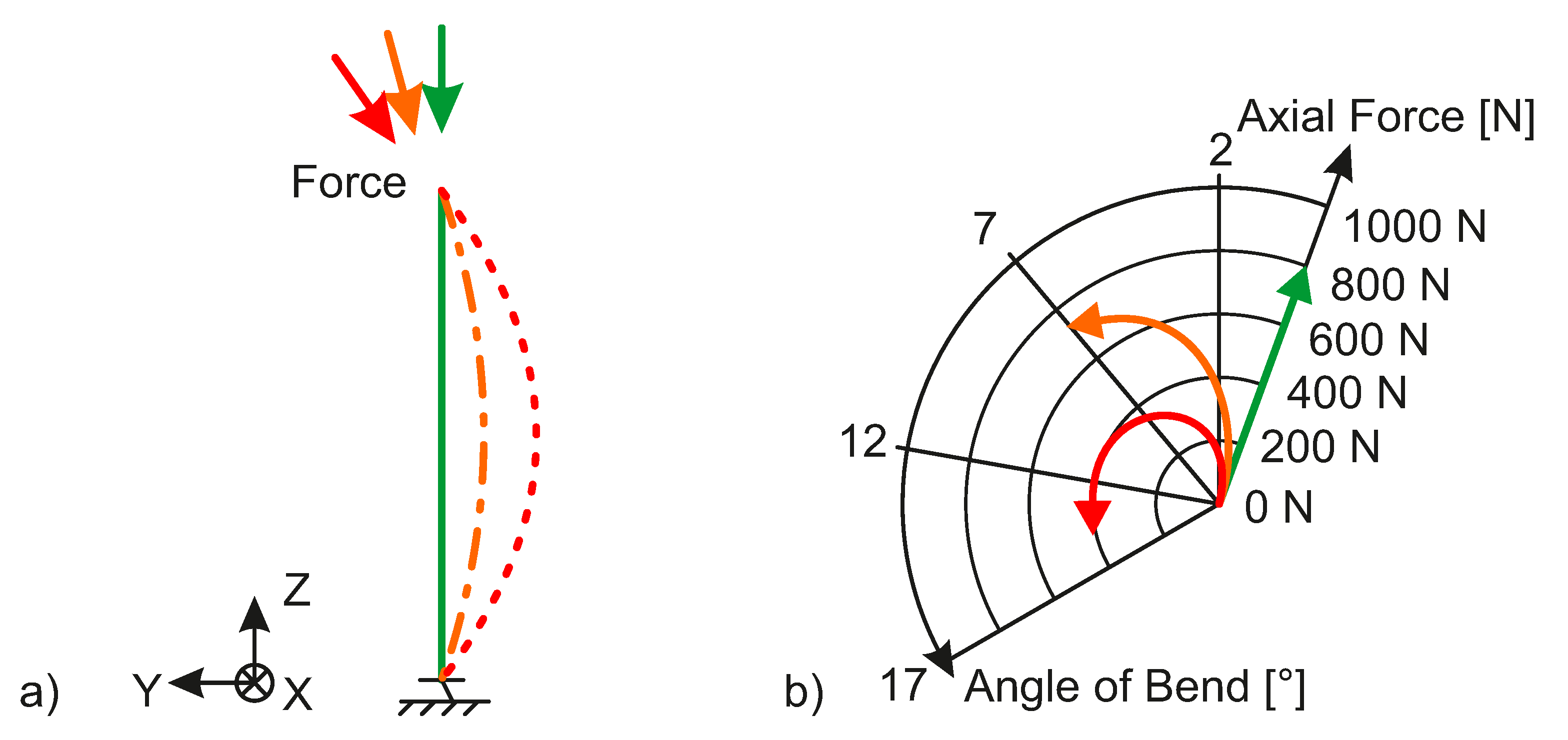
- Uniaxial force measurement: Force transducers for uniaxial force measurement in the longitudinal direction of the pole have been reported in all known investigations. In addition to the longitudinal force, the athlete also introduces other loads, i.e., forces and moments, into the pole due to the complex motions. A recording of all the loads introduced by the athlete into the pole has not been reported. In particular, the moments which have no effect on the propulsion but are decisive for the deflection of the pole could not yet be measured. The relation of introduced moments and the efficiency of the running technique is an open sport-scientific question and cannot be solved using current systems. However, the answer to the aforementioned question becomes more relevant since modern poles have higher bending stiffness than older poles. Thus, they can absorb higher non-propulsion bending loads without great deformation.
- Weight of measurement unit: In the case of uniaxial, strain-based force transducers, transverse forces on the transducer must be avoided. Otherwise, the signal is distorted by cross-talk due to inevitable bending moments. The housing of the transducer typically features a shear force decoupling, in order to correctly measure the uniaxial force. Despite the effort to use adapted designs and lightweight materials, the transducer housing or specific external sleeves, e.g., as developed in [13], add most of the weight to the measurement unit. It should be noted that the need for a transverse force decoupling hinders a further decrease in the weight in case of the common measurement solutions for pole forces. Therefore, a solution without the need for a shear force decoupling has to be developed.
- Signal provision: The mobile measurement systems allow for an online recording of the force data on the track. However, a visualisation and analysis of the measurement data can only be carried out after the investigations, for the time being. Wireless data transmission on computers or smartphones has not yet been reported in the literature. This would offer the possibility of live-feedback training and enable the design of a smart pole, which can be applied also for mass sports application, e.g., as self-tracking device.
2. Results
- High-performance specialized and miniaturized lightweight electronic system for data acquisition and amplification;
- Wireless transmission of the acquired data via a Bluetooth connection;
- Individualized software solution for the signal provision including a method for transmitting vast amounts of data through Bluetooth Low Energy (BLE);
- Android app for receiving acquired data from the specialized measuring system.
3. Functional Design
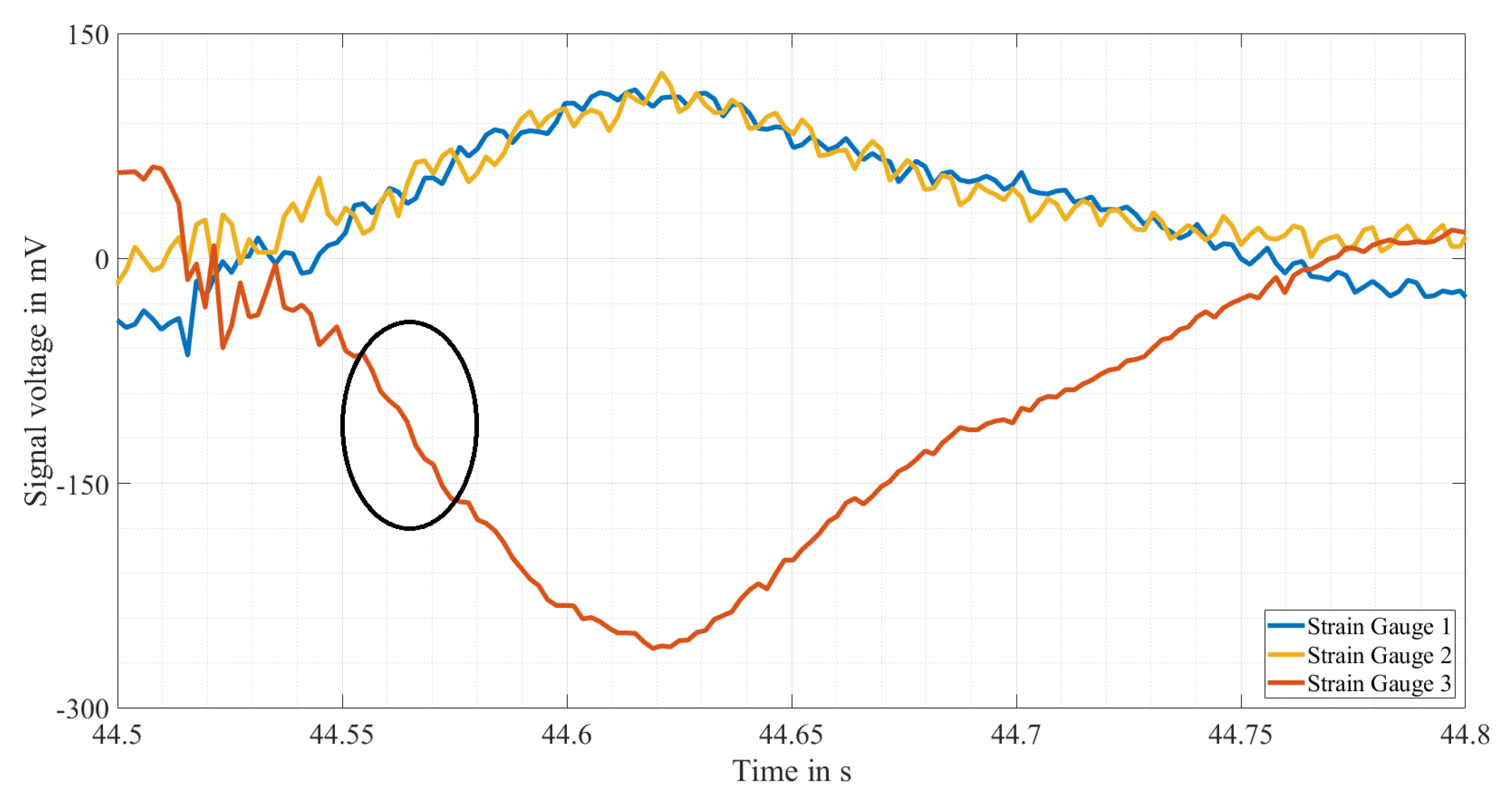
- Measurement of the strain that the ski pole undergoes at its outer circumference to determine the force acting on the pole and its bend;
- Measurement of the acceleration due to gravity in three dimensions acting on the ski pole to determine the position of the pole in space;
- Transmission and storage of the recorded measured values for further processing;
- Calculation of the required information for the athlete’s training from the stored measured values;
- Display of training information in a clear, understandable and easy-to-use format.
- Configuration, calibration and monitoring of the measuring system;
- Formatting, compression and protection of data before and during transfer;
- Safe and permanent storage of the data.
- Huawei Mate 20 Pro;
- Huawei P-20;
- Samsung Galaxy A3 (2016);
- Samsung Galaxy S10;
- Xiaomi Mi 8;
- Xiaomi Redmi 4.
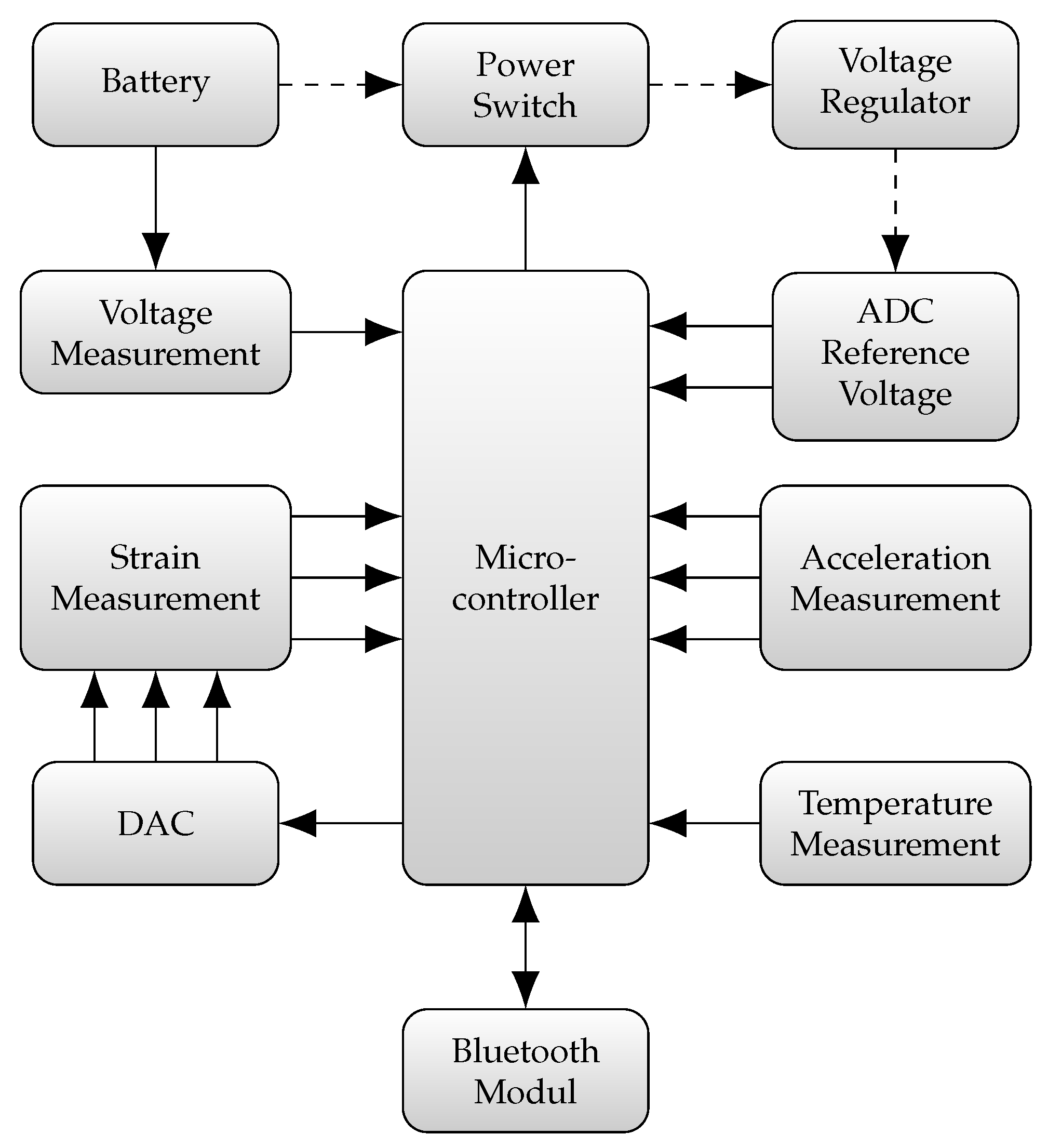
4. Embedded System
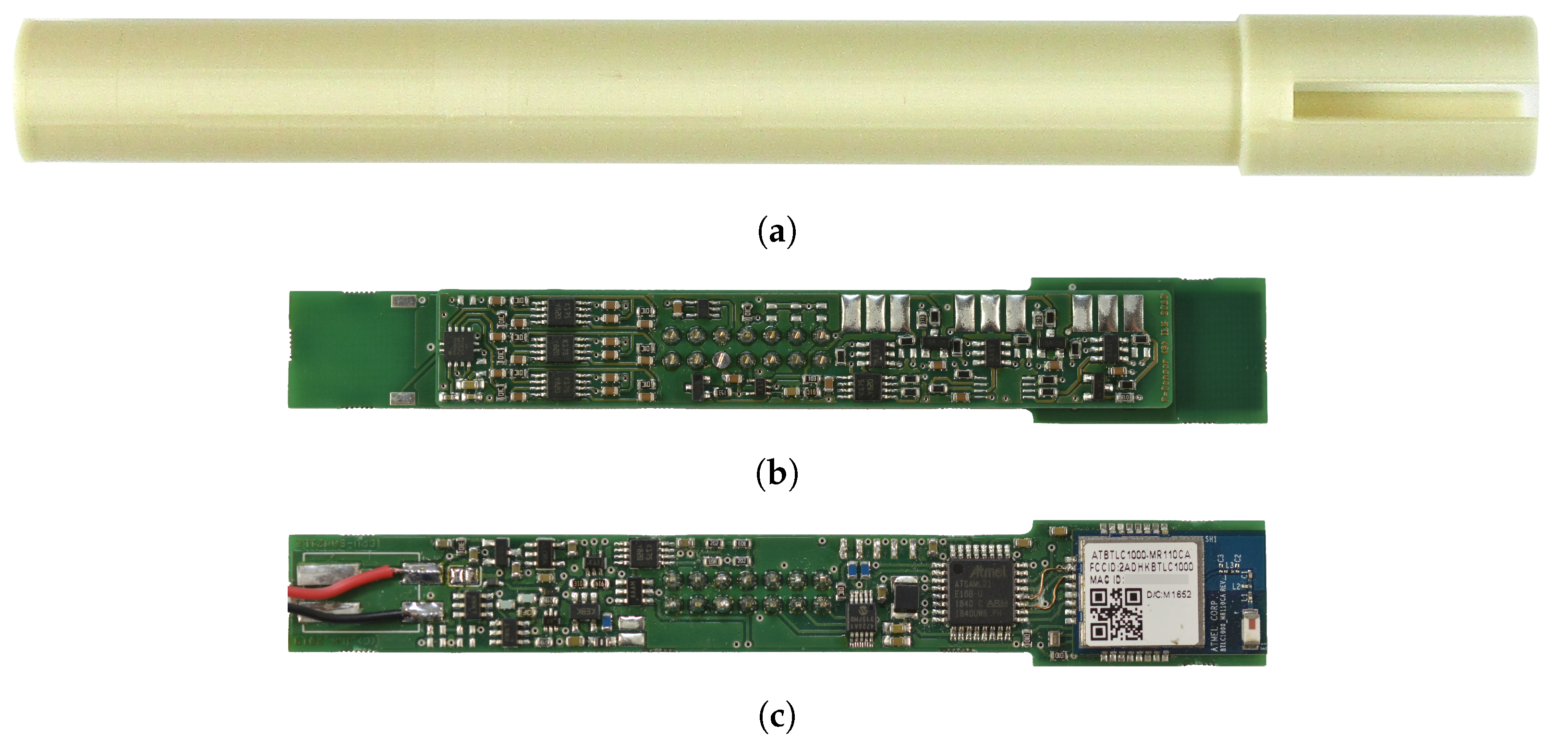
4.1. Mechanical Design
4.2. Hardware Design
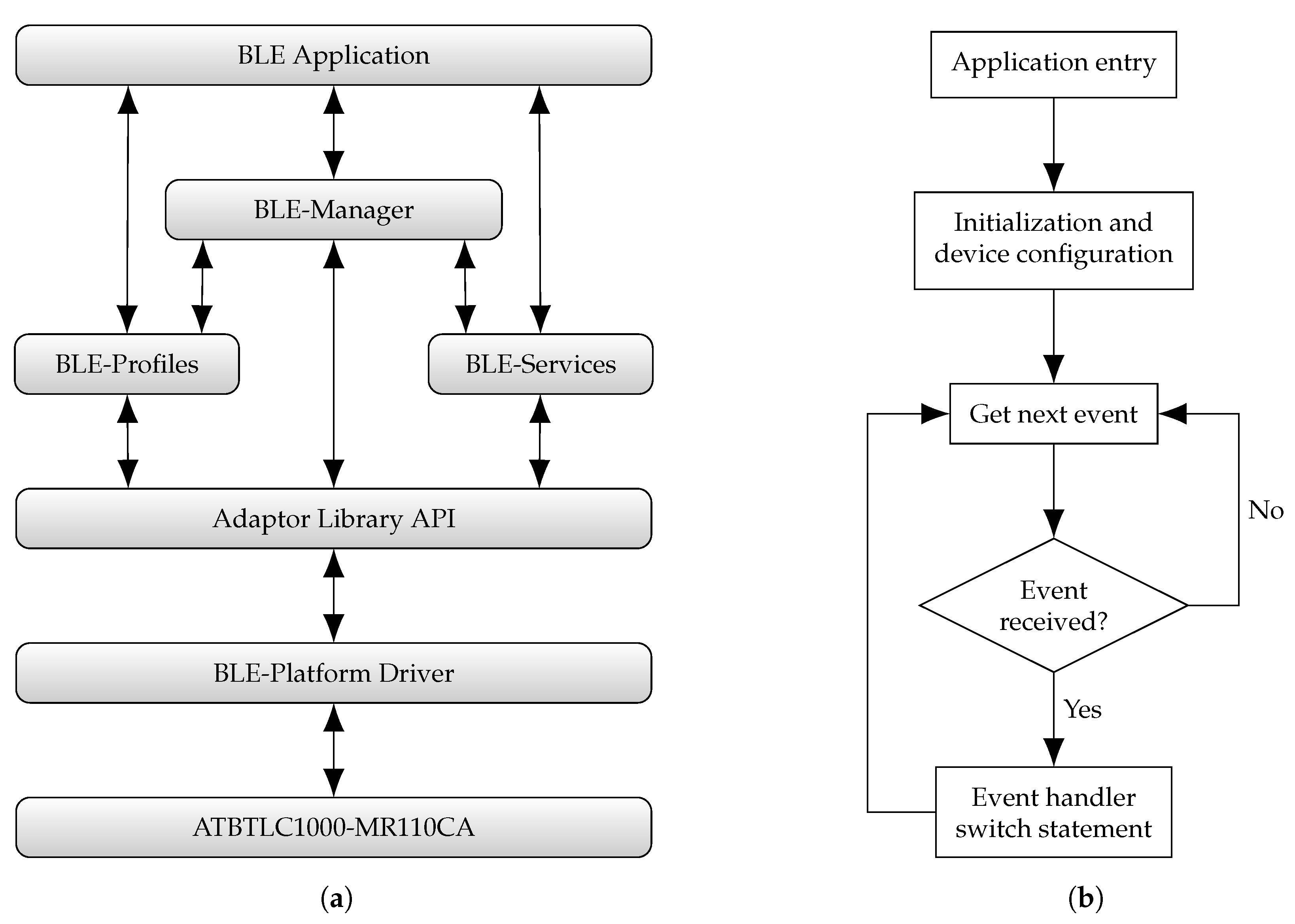
4.3. Software Design
- Basic initialization of the MC;
- Initialization of components relevant for the application (common control signals, timer, ADC, communication interfaces for Bluetooth module and external DAC, event system);
- Hardware calibration (ADC, strain measurement chains);
- Start monitoring the battery voltage;
- Initialization of the Bluetooth module;
- Initialization of the BLE-services (device information service, configuration data service, measurement data service);
- Start of Bluetooth advertising information transmission.
- The Bluetooth advertising information is broadcast for five minutes without establishing a Bluetooth connection.
- After establishing a Bluetooth connection, the measurement data service is not activated within one minute.
- The application initiates the Bluetooth disconnection but does not receive a confirmation event from the BluSDK within one minute.
5. Smartphone
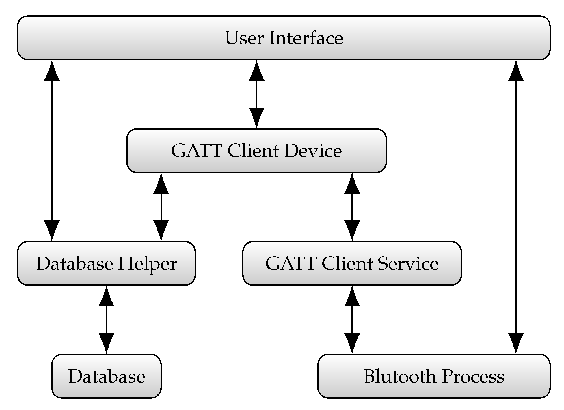
5.1. Software Design
- compileSDKVersion 29
- targetSDKVersion 26
- minSDKVersion 23
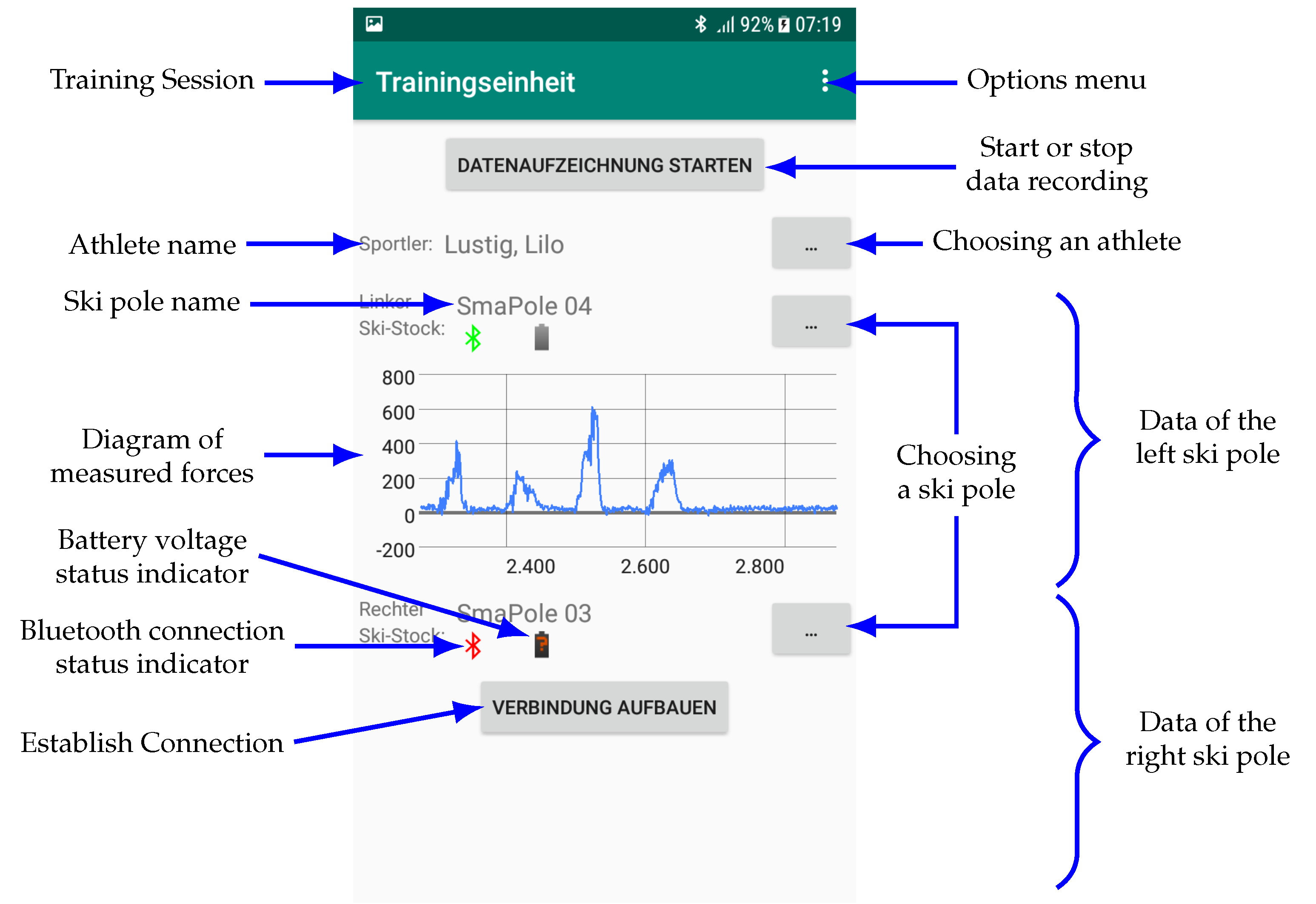
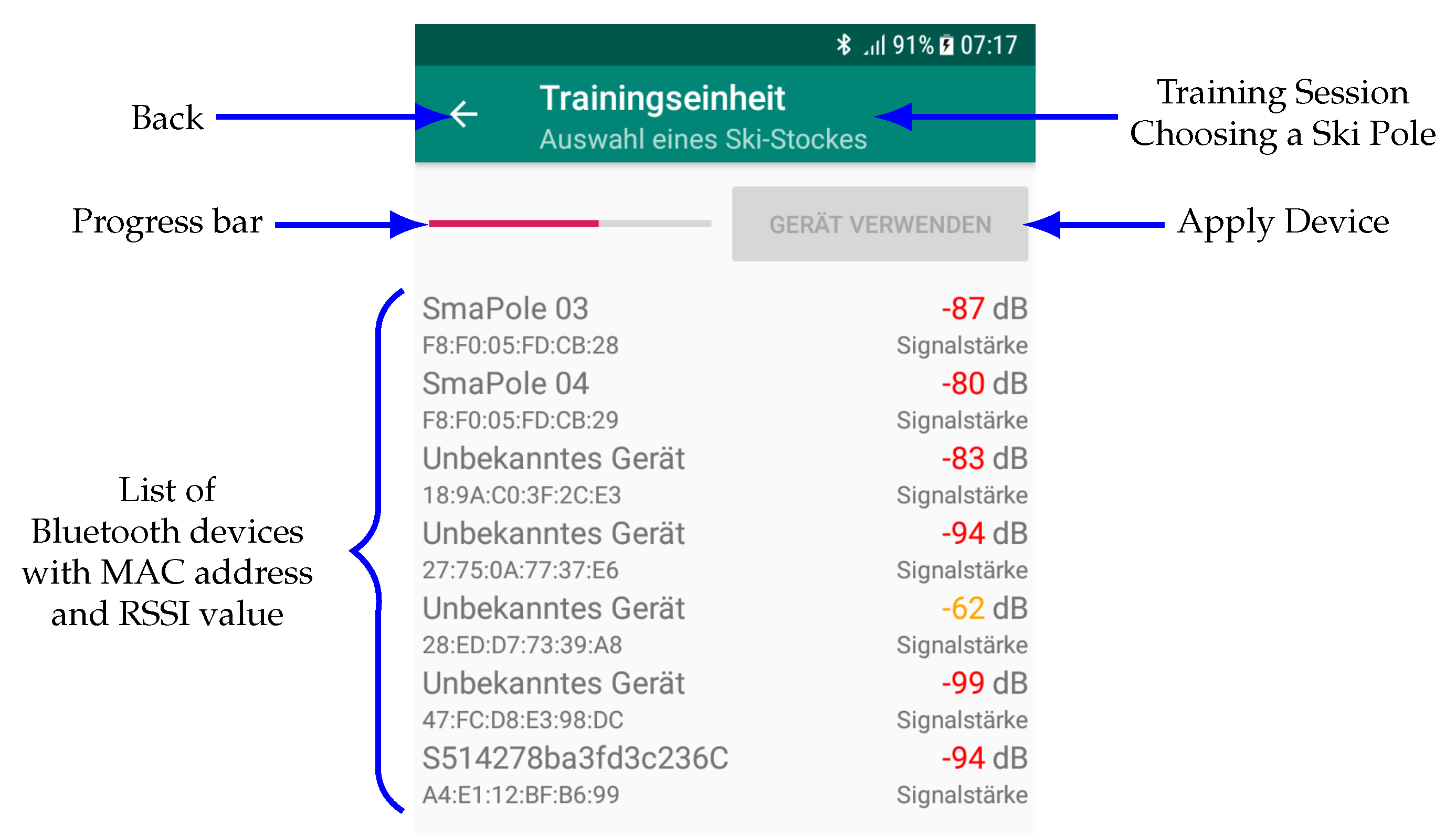
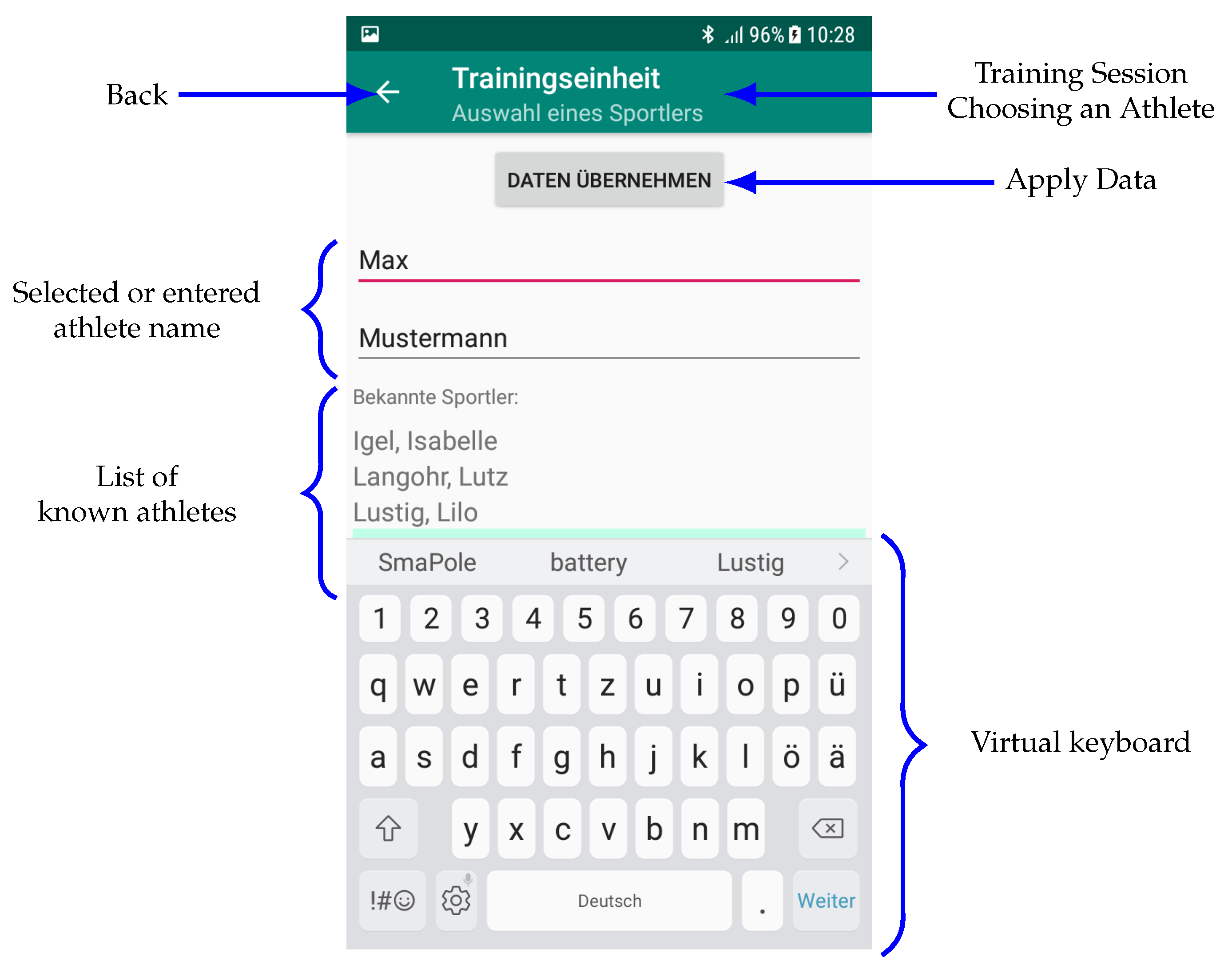
5.2. User Interface
- Get the handle of the Bluetooth system service (BluetoothManager);
- Test if the smartphone supports BLE;
- Get a handle for the Bluetooth adapter;
- Test if Bluetooth is available for the application;
- Test if the application has been granted the required access rights and request them from the user if necessary;
- Connect to the database;
- Display the training session view.
6. Conclusions
Author Contributions
Funding
Acknowledgments
Conflicts of Interest
References
- Vähäsöyrinki, P.; Komi, P.; Seppälä, S.; Ishikawa, M.; Kolehmainen, V.; Salmi, J.; Linnamo, V. Effect of Skiing Speed on Ski and Pole Forces in Cross-Country Skiing. Med. Sci. Sport Exerc. 2008, 40, 1111–1116. [Google Scholar] [CrossRef] [PubMed]
- Nilsson, J.; Jakobsen, V.; Tveit, P.; Eikrehagen, O. Pole length and ground reaction forces during maximal double poling in skiing. Sport. Biomech. 2003, 2, 227–236. [Google Scholar] [CrossRef] [PubMed]
- Clauß, M.; Herrmann, H. Angewandte Biomechanik im Leistungssport am Beispiel des Skatens im Biathlon. In Biomechanik als Anwendungsforschung-Transfer Zwischen Theorie und Praxis; Czwalina: Hamburg, Germany, 2004; pp. 50–57. [Google Scholar]
- Millet, G.; Hoffman, M.; Candau, R.; Clifford, P. Poling forces during roller skiing: Effects of technique and speed. Med. Sci. Sport Exerc. 1998, 30, 1645–1653. [Google Scholar] [CrossRef] [PubMed]
- Holmberg, H.; Lindinger, S.; Stöggl, T.; Eitzlmair, E.; Müller, E. Biomechanical analysis of double poling in elite cross-country skiers. Med. Sci. Sport Exerc. 2005, 37, 807–818. [Google Scholar] [CrossRef] [PubMed] [Green Version]
- Stöggl, T.; Kampel, W.; Müller, E.; Lindinger, S. Double-push skating versus V2 and V1skating on uphill terrain in cross-country skiing. Med. Sci. Sport Exerc. 2010, 42, 187–196. [Google Scholar] [CrossRef] [PubMed]
- Stöggl, E.; Holmberg, H. Three-dimensional Force and Kinematic Interactions in V1 Skating at High Speeds. Med. Sci. Sport Exerc. 2014, 47, 1232–1242. [Google Scholar] [CrossRef] [PubMed]
- Göpfert, C.; Holmberg, H.; Stöggl, T.; Müller, E.; Lindinger, S. Biomechanical characteristics and speed adaptation during kick double poling on roller skis in elite cross-country skiers. Sport. Biomech. 2013, 12, 154–174. [Google Scholar] [CrossRef] [PubMed]
- Pellegrini, B.; Bortolan, L.; Schena, F. Poling force analysis in diagonal stride at different grades in cross country skiing. Scand. J. Med. Sci. Sport. 2011, 21, 589–597. [Google Scholar] [CrossRef] [PubMed]
- Wank, V.; Heger, H.; Schwarz, M.; Rapp, W.; Blab, F.; Schwarz, O. Entwicklung von leistungsdiagnostischen Methoden im Langlauf der Sitzschlittenfahrerinnen und -fahrer (AZ 080402/11). In BISp-Jahrbuch Forschungsförderung 2011/12; Sportverlag Strauß: Cologne, Germany, 2012; pp. 101–106. [Google Scholar]
- Hladnik, J.; Supej, M.; Jerman, B. Force Measurement System for Roller-Ski Skating. Tehnički Vjesnik 2018, 25, 1291–1297. [Google Scholar]
- Nikkola, A.; Särkkä, O.; Suuriniemi, S.; Kettunen, L. Pole force and inertial measurements to analyze cross-country skiing performance in field conditions. Proc. Inst. Mech. Eng. Part P J. Sport. Eng. Technol. 2018, 232, 323–333. [Google Scholar] [CrossRef]
- Wank, V.; Heger, H.; Rapp, W. Optimierung der Lauftechnik entsprechend den individuellen Voraussetzungen der Athleten im Sitzschlitten-Skilanglauf (AZ IIA1-070403/13). In BISp-Jahrbuch 2012/13; Sportverlag Strauß: Cologne, Germany, 2014; pp. 141–146. [Google Scholar]
- Henriques, J.; Neves, N.; de Carvalho, P. Design of Device for Measuring the Load of Cross-Country Ski Poles. In Proceedings of the XV Mediterranean Conference on Medical and Biological Engineering and Computing—MEDICON 2019, Coimbra, Portugal, 26–28 September 2019; Springer International Publishing: Cham, Switzerland, 2020; pp. 640–649. [Google Scholar]
- Modler, N.; Winkler, A.; Filippatos, A.; Weck, D.; Dannemann, M. Function–integrative Lightweight Engineering–Design Methods and Applications. Chemie Ingenieur Technik 2020, 92, 949–959. [Google Scholar] [CrossRef]
- Filippatos, A.; Höhne, R.; Maron, B.; Holeczek, K.; Kostka, P.; Modler, N. Development of a composite, load-adaptive leaf spring: A multi-domain approach. In Proceedings of the 6th International Conference on Experiments/Process/System Modeling/Simulation/Optimization (6th IC-EpsMsO), Athens, Greece, 8–11 July 2015. [Google Scholar]
- Filippatos, A.; Höhne, R.; Kliem, M.; Gude, M. A composite-appropriate integration method of thick functional components in fibre-reinforced plastics. Smart Mater. Struct. 2016, 25, 35026. [Google Scholar] [CrossRef]
- Weck, D.; Sauer, S.; Adam, F.; Starke, E.; Böhm, R.; Modler, N. Embedded Sensor Networks for Textile-Reinforced Thermoplastics: Sensor Network Design and Mechanical Composite Performance. Adv. Eng. Mater. 2016, 18, 444–451. [Google Scholar] [CrossRef]
- Steinbild, P.; Höhne, R.; Füßel, R.; Modler, N. A sensor detecting kissing bonds in adhesively bonded joints using electric time domain reflectometry. NDT E Int. 2019, 102, 114–119. [Google Scholar] [CrossRef]
- Hohlfeld, K.; Eßlinger, S.; Eydam, A.; Winkler, A.; Weber, T.; Gude, M.; Modler, N.; Gerlach, G.; Michaelis, A.; Schönecker, A.; et al. Integration of Piezoceramic Composites into Structural Components: Effect on the Polarisation State and Polarisability. J. Ceram. Sci. Technol. 2019, 10, 19–26. [Google Scholar]
- Höhne, R.; Filippatos, A.; Pärschke, R.; Modler, N.; Schürer, A.; Wilhelm, A. Evaluation eines innovativen Monitoringsystems zur uniaxialen Stockkraftmessung mittels applizierter Dehnmessstreifen–EviS. In BISp-Jahrbuch Forschungsförderung 2016/17, 1st ed.; Jahrbücher des Bundesinstituts für Sportwissenschaft, Sportverlag Strauß: Hellenthal, Germany, 2018; pp. 297–301. [Google Scholar]
- Steinbild, P.J.; Hentschel, U.; Schwaar, A.; Dannemann, M.; Modler, N.; Schürer, A.; Wilhelm, A. Strain-based monitoring system for ski poles with low impact on their total mass and inertia. Procedia Manuf. 2020, 52, 187–192. [Google Scholar] [CrossRef]
- Bluetooth SIG. Bluetooth Core Specification; Version 5.2; Bluetooth SIG: San Jose, CA, USA, 31 December 2019. [Google Scholar]
- Microchip Technology Inc. SAM L21 Family Data Sheet; Microchip Technology, Inc.: Chandler, AZ, USA, 2019. [Google Scholar]
- Microchip Technology Inc. TB3185–ADC Gain and Offset Error Calibration on ARM® Cortex®-M0+ Based MCUs; Microchip Technology, Inc.: Chandler, AZ, USA, 2018. [Google Scholar]
- Microchip Technology Inc. ATBTLC1000-MR110CA Ultra-Low Power BLE Module; Microchip Technology, Inc.: Chandler, AZ, USA, 2019. [Google Scholar]
- Microchip Technology Inc. ATBTLC1000 BluSDK v6.2 Release Notes; Microchip Technology, Inc.: Chandler, AZ, USA, 2018. [Google Scholar]
- Microchip Technology Inc. ATBTLC1000 BluSDK BLE API Software Development Guide; Microchip Technology, Inc.: Chandler, AZ, USA, 2018. [Google Scholar]
- Gamma, E.; Helm, R.; Johnson, R.; Vlissides, J. Design Patterns: Elements of Reusable Object-Oriented Software, 1st ed.; Addison-Wesley Professional Computing Series; Addison-Wesley Professional: Boston, MA, USA, 1995. [Google Scholar]


| Characteristic | Measuring Module | Signal Processing Module |
|---|---|---|
| Basic | 2 Wheatstone Bridges; | Microcontroller Arduino Nano Board; |
| electronic | Bi-Level Signal Amplifier; | Serial Bluetooth Link Bluefruit EZ-Link; |
| devices | 2D-Accelerometer | Li-Ion Battery, 3.7 V, 1950 mAh; |
| Mini USB Connector for | ||
| Charging and Data Transfer; | ||
| Charge Display | ||
| Weight | 10 g | 100 g |
| Dimensions | 34 mm × 25 mm × 15 mm | 80 mm × 45 mm × 28 mm |
| (with housing) | ||
| Positioning | Pole | Drink belt |
| Characteristic | Property |
|---|---|
| Package | TQFP32 (nominal size: 9 mm × 9 mm) |
| CPU | ARM Cortex-M0+ |
| Memory | 256 kB Flash (programm memory); |
| 32 kB SRAM (main memory); | |
| 8 kB SRAM (low power memory); | |
| 8 kB EEPROM | |
| Peripherals | 12-bit, 1 Msps ADC with up to 10 channels; |
| Up to three 16-bit timer/counter; | |
| 32-bit real time counter; | |
| 16-channel DMAC; | |
| 12-channel event system; | |
| Up to six serial communication interfaces |
| Characteristic | Property |
|---|---|
| Dimensions | 12.700 mm × 20.152 mm |
| Transmit power | −55 dBm to 3.5 dBm |
| Power supply voltage | 1.8 V to 4.3 V (power management unit); |
| 1.62 V to 4.3 V (general purpose input/output) |
Publisher’s Note: MDPI stays neutral with regard to jurisdictional claims in published maps and institutional affiliations. |
© 2021 by the authors. Licensee MDPI, Basel, Switzerland. This article is an open access article distributed under the terms and conditions of the Creative Commons Attribution (CC BY) license (https://creativecommons.org/licenses/by/4.0/).
Share and Cite
Hentschel, U.; Steinbild, P.J.; Dannemann, M.; Schwaar, A.; Modler, N.; Schürer, A. Functional Design Employing Miniaturized Electronics with Wireless Signal Provision to a Smartphone for a Strain-Based Measuring System for Ski Poles. Computers 2021, 10, 77. https://0-doi-org.brum.beds.ac.uk/10.3390/computers10060077
Hentschel U, Steinbild PJ, Dannemann M, Schwaar A, Modler N, Schürer A. Functional Design Employing Miniaturized Electronics with Wireless Signal Provision to a Smartphone for a Strain-Based Measuring System for Ski Poles. Computers. 2021; 10(6):77. https://0-doi-org.brum.beds.ac.uk/10.3390/computers10060077
Chicago/Turabian StyleHentschel, Uwe, Philip Johannes Steinbild, Martin Dannemann, Andree Schwaar, Niels Modler, and Axel Schürer. 2021. "Functional Design Employing Miniaturized Electronics with Wireless Signal Provision to a Smartphone for a Strain-Based Measuring System for Ski Poles" Computers 10, no. 6: 77. https://0-doi-org.brum.beds.ac.uk/10.3390/computers10060077