
Separable Reversible Data Hiding in Encryption Image with Two-Tuples Coding


1
Faculty of Computing and Informatics, University Malaysia Sabah (UMS), Kota Kinabalu 88400, Sabah, Malaysia
2
Faculty of Information and Statistics, Guangxi University of Finance and Economics, Nanning 530003, China
*
Author to whom correspondence should be addressed.
Computers 2021, 10(7), 86; https://0-doi-org.brum.beds.ac.uk/10.3390/computers10070086
Submission received: 17 June 2021
/
Revised: 1 July 2021
/
Accepted: 4 July 2021
/
Published: 7 July 2021
Abstract
:Separable Reversible Data Hiding in Encryption Image (RDH-EI) has become widely used in clinical and military applications, social cloud and security surveillance in recent years, contributing significantly to preserving the privacy of digital images. Aiming to address the shortcomings of recent works that directed to achieve high embedding rate by compensating image quality, security, reversible and separable properties, we propose a two-tuples coding method by considering the intrinsic adjacent pixels characteristics of the carrier image, which have a high redundancy between high-order bits. Subsequently, we construct RDH-EI scheme by using high-order bits compression, low-order bits combination, vacancy filling, data embedding and pixel diffusion. Unlike the conventional RDH-EI practices, which have suffered from the deterioration of the original image while embedding additional data, the content owner in our scheme generates the embeddable space in advance, thus lessening the risk of image destruction on the data hider side. The experimental results indicate the effectiveness of our scheme. A ratio of 28.91% effectively compressed the carrier images, and the embedding rate increased to 1.753 bpp with a higher image quality, measured in the PSNR of 45.76 dB.
1. Introduction
In recent years, the problem of information security has become increasingly prominent, and privacy has attracted much attention. As a significant branch of data hiding, Reversible Data Hiding (RDH) technology can achieve the purpose of secret transmission and content authentication by embedding additional data in the carrier image. RDH has been widely used to protect military and medical industries, remote sensing, and commercial image processing applications [1,2,3,4]. However, the dramatic growth of digital images and the continuous expansion of their applicability in supporting the emerging technologies fields has heralded a revolution in traditional RDH schemes [5,6,7,8].
Unlike traditional RDH practices, the content owners of clinical, military, security, and social cloud services providers are urged to hide the sensitive details of original images, leading to the birth of Reversible Data Hiding in Encryption Image (RDH-EI) [9]. In RDH-EI schemes, additional confidential data can be embedded into the encrypted image without destroying the carrier image. For example, today’s healthcare providers suffered a perilous patients privacy situation when they outsource image processing to third parties to process and store patient’s sensitive data without falling foul of ever-changing data protection and privacy legislation. In order to secure these sensitive and confidential data, as well as minimize the exposure in the event of a data breach, it is necessary to embed these patient’s sensitive data in the encrypted medical image in order to allow these encrypted data can be processed, classified and searchable by third parties. The rule of thumb is that the embedded sensitive data must not affect the process of accurately recovering encrypted medical images [5,10,11]. Otherwise, it may cause misdiagnosis, ineffective treatment and resulting in unimaginable severe effects. Another empirical example of RDH-EI in protecting user privacy in cloud service applications [12,13,14]. The user preserves his privacy by encrypting his image and uploading it to the cloud server. On the other hand, the third-party cloud service providers need to embed the additional data in the encrypted user image for facilitating the cloud services and management. Indeed, the naïve approach passes the user’s data hiding key to the cloud service providers to decrypt the encrypted image. However, it will incur the disclosure of user privacy. RDH-EI scheme can ensure that the user can retrieve and recover the encrypted image in the plaintext domain, yet empowering that the cloud service providers can accurately extract information from the encrypted image and process it. Additionally, RDH-EI scheme can be further extended to support several real-world applications, such as managing credit records in financial services, court records in government agencies, image processing in military applications, and commercial image processing software [15,16,17,18].
As encrypted images often contain sensitive personalized data, privacy protection has proven to be substantially enormous in processing, storing and managing images. Hence, various RDH-EI schemes have been put forward by recent researchers. Compared with the existing RDH-EI scheme [19,20,21,22,23,24,25,26,27,28,29,30,31,32,33,34,35,36,37,38,39,40,41,42,43], our main contributions are as follows:
- A new two-tuples coding compression method is proposed, which can be utilized in the field of data hiding, yet it serves as an alternative method of lossless image compression. The proposed two-tuples coding effectively compresses the high-order bits of carrier image and produces large independent redundant space, resulting in a higher compression ratio.
- Our RDH-EI scheme eliminates (i) the conventional process of integrating additional image encryption algorithms by directly generating an encrypting image during image coding, and (ii) the pre-requisite for the content owner to prepare the embeddable space in advance. Consequently, the proposed RDH-EI scheme significantly lessens the complexity of recent RDH-EI schemes and minimizes the risk of destroying image in data hider side when embedding additional data.
- In our RDH-EI scheme, the additional data are embedded independently of the carrier image in the redundancy filling bits, and this ensures that image restoration and additional data extraction are separable and reversible.
- Our RDH-EI scheme has a high generality property, which can accommodate any form and feasible size of the carrier image.
- The proposed RDH-EI scheme is constructed based on Vacating Room by Encryption (VRBE). Therefore, it enjoys a higher security level compared to the conventional Vacating Room after Encryption (VRAE) and Reserving Room before Encryption (RRBE).
2. RDH-EI and Related Works
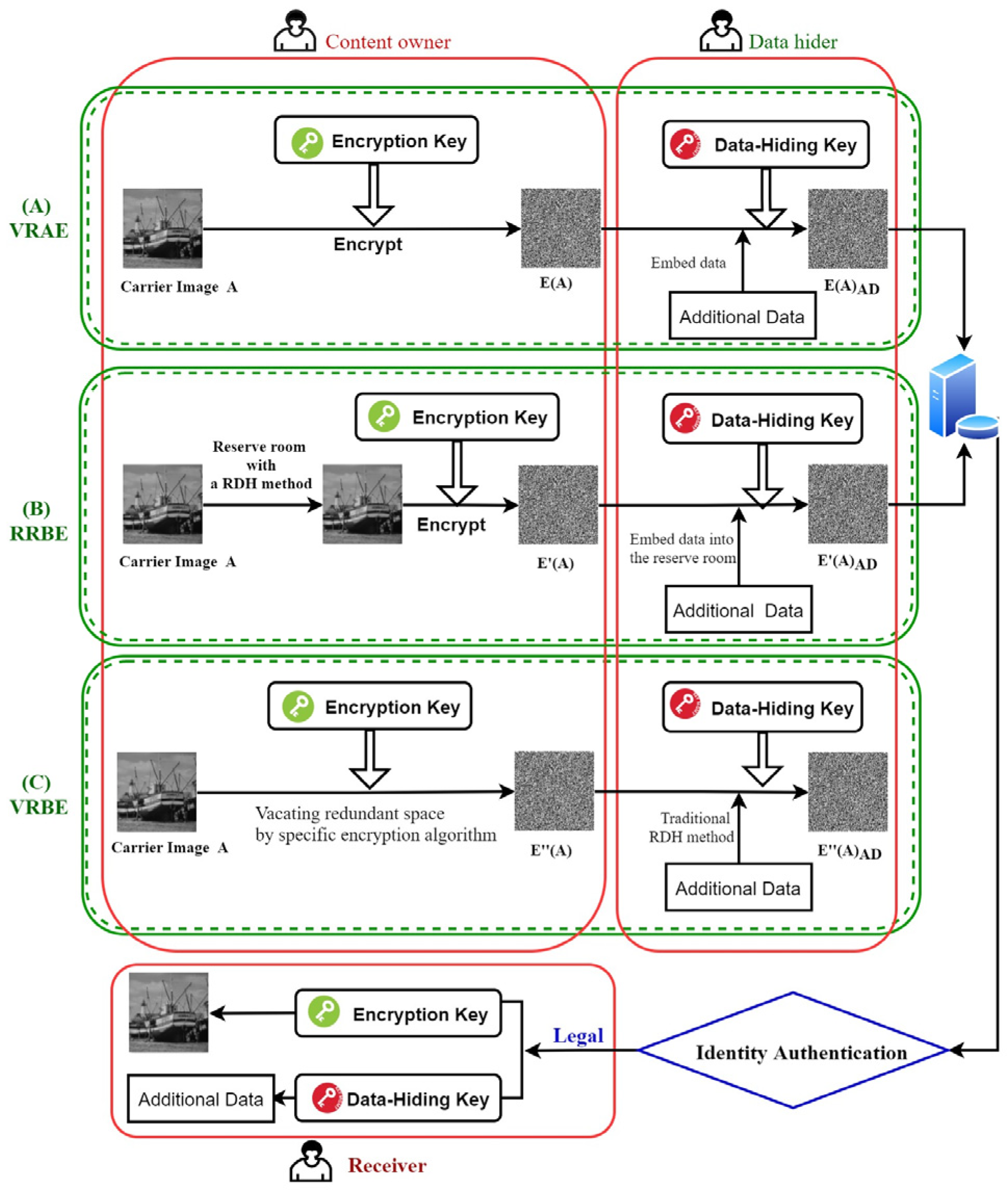
In recent years, numerous RDH-EI schemes have been proposed to achieve efficiency in embedding rate, security, reversibility, and separability over the last decades. In general, the existing RDH-EI schemes [19,20,21,22,23,24,25,26,27,28,29,30,31,32,33,34,35,36,37,38,39,40,41,42] can be classified into three methods, namely: Vacating Room after Encryption (VRAE) [19,20,21,22,23,24,25,26,27,28,29,30,31], Reserving Room before Encryption (RRBE) [32,33,34,35,36,37,38], and Vacating Room by Encryption (VRBE) [39,40,41,42]. The framework of VRAE, RRBE, VRBE and their characteristics are further illustrated in Figure 1.
Let is the carrier image, are the encrypted image with the method of VRAE, RRBE and VRBE respectively, and are the output of embedding data into the encrypted image of respectively. Figure 1A shows the construction of RDH-EI scheme by using the VRAE method. In the VRAE method, the content owner first encrypts the carrier image, to get the encrypted image, and passes the encrypted image to the data hider. The data hider tries to make as much space as possible from the to embed more additional data, to obtain. Figure 1B illustrates the RDH-EI creation with the RRBE method. In the RRBE method, the content owner first reserves part of the space in the carrier image, by applying a traditional RDH method, then encrypts it to get the encrypted image, . The data hider embeds the additional data, into the encrypted part corresponding to the reserved space for generating . The application of VRBE method in constructing the RDH-EI framework is demonstrated in Figure 1C. In the VRBE method, the content owner designs the image encryption method to construct the encrypted image that contains a redundant space. The data hider uses the traditional RDH method to embed additional data, in the redundant space, which generally has a sizeable redundant space. Details of mathematical notations and abbreviations can be further referred in Appendix A (Table A1 and Table A2).
- Vacating Room After Encryption (VRAE) Method
The concept of VRAE was first proposed by Zhang [9] in 2011. Zhang splits the encrypted image, into nonoverlapping blocks. The pixels of each block are pseudo-randomly divided into two sets by using a data-hiding key, then flipping three Least Significant Bits (LSBs) according to the embedded additional data. However, the recovering of the carrier image, in Zhang’s scheme [9] requires an extra fluctuation function and contains some errors. Liao et al. [19] argued that Zhang’s [9] fluctuation function ignores four pixels on the boundary of each block, and subsequently, they improved Zhang’s fluctuation function by reducing its error rate. While Hong et al. [20] considered the boundary pixels in constructing RDH-EI, their approach limited to the use of two pixels in calculating the smoothness of the image block. Using three or four adjacent pixels in calculating the image block’s complexity will significantly increase the recovered image’s accuracy. Qin et al. [21] still rely on the flipping LSBs techniques in essence, but with some improvements in selecting the flipped position and adopting an adaptive judgment function in restoring the image based on the local content distribution feature of the image. Thus, Qin et al.’s [21] technique effectively reduces the error rate of the VRAE method. Wang et al. [22] also follow the blueprint of Zhang’s method [9] by proposing a block-level image encryption method. The embedding position can be located quickly with their proposed self-embedding method, and the generated error rate of fluctuation function has been reduced. On the other hand, Zhang [23] attempted to achieve reversible and separable properties by proposing a separable reversible data hiding scheme for the encrypted image. In Zhang’s RDH-EI scheme [23], the content owner encrypts the carrier image, first, then the data hider compresses the LSBs of the encrypted image, thus creating a sparse space to embed the additional data, . Xu and Wang [24] encrypt carrier image, with the stream cipher, and the interpolation errors of the other nonsample pixels are encrypted. The improved histogram shift and differential expansion techniques are used to embed the additional data into the interpolation error. Meanwhile, a group of researchers [25,26,27,28,29,30,31,32] is aiming to improve the embedding rate and computational complexity of the VRAE method. Argawal and Kumar [25] aimed to lessen the computational complexity of RDH-EI by exploiting the concepts of additive modulo 256 to encrypt the carrier image and preserved mean values to extract information and restore the image with the accuracy of 100 percent. However, their scheme suffered from the low embedding rate as involving bit-by-bit encryption. Singh and Raman [26] apply Chinese Remainder Theorem (CRT) to encrypt the carrier information and distributes it to multiple shares, then embeds the additional in some of these shares with the data hiding key. Qin et al. [27] encrypt the pixel blocks with analogues stream ciphers and divide the encrypted blocks into two groups corresponding to the carrier image’s smooth and complex areas. Then, Qin et al. [27] improved the embedding rate by compressing the smooth area to generate redundant space. By encrypting the blocks with a stream cipher and displacement, Zhang et al. [28] further enhanced Qin et al.’s [27] scheme, then the additional data, , are embedded in the Most Significant Bit (MSB) layer of some pixels in the smooth area block, resulted in this method can embed data twice and achieve satisfactory image quality decryption.
Unlike the use of stream cipher approach in Xu and Wang [24] and Qin et al. [27] RDH-EI schemes, Yi et al. [29] used pixel correlation in the image block, and obtained redundant space by using block-level prediction error. Then, they encrypted the image to retain the original redundant space by applying block replacement in order to obtain a higher embedding rate and better visual quality of the image. Di et al. [30] divided the encrypted image, into two sub-images by using bit plane-level operations and embedded additional data, with an adaptive embedding strategy. Although this method improves the embedding rate, the image quality measured in Peak Signal-to-Noise Ration (PSNR) of the encrypted image is low and it only suitable for some specific types of carrier images. Yu et al. [31] split the carrier image into nonoverlapping blocks, arranged the created image blocks, scanned each block to generate a one-dimensional pixel sequence with a closed Hilbert curve, and transform it into an encrypted image,. Then, the additional data, , were embedded by transforming the histogram, thus effectively improving the embedding capability and security level. To enhance the prediction of the current pixel, Xu and Su [32] used the linear weighting of three adjacent pixels in the row, then applied a modular operation to encrypt the pixel value in each row and embed the additional data by changing the differential histogram.
- Reserving Room Before Encryption (RRBE) Method
To overcome the low embedding rate of the VRAE method and incomplete restoration of the carrier image, the content owner in RRBE methods [33,34,35,36,37,38,39] employs preprocessing concepts to reserve the embedding space of carrier image, , in the plaintext domain. Cao et al. [33] used sparse coding to generate ample compression space and achieve significant embedding capacity by mining the correlation between neighboring pixels, and data extraction and carrier image restoration were separable. To obtain a higher embedding rate, Han et al. [34] employed Huffman coding to compress the error between the original image and the estimated image. Qian et al. [35] embedded various amounts of additional data, , into the three channels of the encrypted image; however, the performance of the embedding rate heavily relies on the chosen parameters. A higher embedding rate can be achieved by selecting the appropriate parameters, while the inappropriateness of the chosen parameters can result in lower embedding rate, and additional data,, cannot be reliably extracted from the carrier image, . Subsequently, Li et al. [36] extended the application of stream cipher in encrypting original carrier image,, by combining with the block substitution technique, thus improving the image quality and embedding rate. Wu et al. [37] achieved the separable properties by splitting the carrier image,, into multiple image blocks with different scales, and adding redundancy for the pixels to vacate more allocated space based on the difference between the average and the block pixel value. Nasrullah et al. [38] employed lifting-based Integer Wavelet Transform (IWT) and Set Partition in Hierarchical Tree (SPIHT) coding to perform lossless compression in encryption domain. The Kd-tree approach was applied to reserve more embedding room for hiding secret data. Yu et al. [39] divided the carrier image,, into reference pixels and nonreference pixels. The embedding additional data process involves the prediction error of the nonreference pixels and the replacement of original nonreference pixels with the prediction error. The use of stream cipher and shuffling strategies in encrypting the image resulted in a higher security level.
- Vacating Room By Encryption (VRBE) Method
Over the last couple of years, VRBE has become a modern approach proposed differently from the conventional VRAE and RRBE methods. VRAE is a part of the method to create redundant space after the encryption process, and the content owner focuses on encrypting the carrier image, . While on the encrypted image, the data hider needs to create redundant space without affecting image recovery accuracy. The entropy of the encrypted image , however, tends towards the limit. Theoretically speaking, hiding data in the encrypted image is tricky, imposes higher requirements for data hider and leads to the low embedding rate, poorly reversible and separable properties.
In contrast, the RRBE method first generates redundant space in the carrier image,, before the encryption process, and the original redundant space has to be retained throughout the encryption process. However, the generation of redundant space often depends on RDH methods. Therefore, the content owner must complete both RDH and image encryption, imposing heavy duties on content owners and putting forward high RDH-EI technology requirements. On the other hand, the VRBE method typically generates redundant space during the encryption process; the content owner only needs to encrypt the carrier image and transmit the redundant space generated during the encryption process directly to the data hider.
As redundant space is independent of the efficient carrier image in the VRBE method, it can ensure separable properties and has apparent advantages over the embedding rate of VRAE and RRBE. Several RDH-EI [40,41,42,43] have been constructed based on VRBE methods recently. Liu et al. [40] generated the encrypted image, , with redundant space by disordering bit-planes and sub-blocks, then used Arnold transform to embed data with general RDH algorithm and lastly transmitted it to the data hider. Thus, it resulted in a low embedding rate of 1.600 bpp and lessened the complexity for the content owner. Yi et al. [41] classified pixels using a binary tree labelling technique, providing different label classification strategies according to different parameters. On this basis, this scheme tolerates significant changes in pixels compared to the conventional data embedding method and achieved an embedding rate of 1.752 bpp. However, the embedding rate would be influenced by the selection of parameters. Tang et al. [42] proposed a new block-based image encryption scheme that transforms the spatial correlation of adjacent pixels of the carrier image into the encrypted image, and combines the designed method of differential compression with the improved Huffman coding, which results in a higher embedding rate and better image quality. Chuan et al. [43] proposed a new RDH-EI scheme based on redundant transmission and sparse block coding. The content owner scrambles and encrypts the bit-plane, blocks and pixels, then transfers the redundant information from MSB to LSB. By applying sparse coding, the data hider embeds additional data, into different types of encrypted blocks to ensure the separation of data extraction, image decryption and recovery. However, this method is not universal and produces additional marker bits under some parameters, which reduces the embedding rate.
- Limitations of Recent RDH-EI Methods
The above comprehensive review of existing RDH-EI schemes highlights the contribution and deficiency of three methods in RDH-EI. In VRAE method, the data hider needs to embed additional data, in the encrypted image without affecting the restoration of the carrier image. However, it is challenging to obtain redundant space in the encrypted image, resulting in low embedding capacity, and errors might occur in data extraction and image restoration. The RRBE method follows the blueprints of RDH algorithm; content owners can choose the appropriate method from the existing RDH methods to generate redundant space and then encrypt the image. The data hider can directly embed additional data, in the reserved space. However, the achieved embedding rate and separability properties are still low due to RDH’s intrinsic structure. On the other hand, the algorithm design of VRBE method can generate a larger embedding space, and efficiently meet the reversible and separability properties. However, we found out that recent VRBEmethods [40,41,42,43] had improved the embedding rate and achieved perfect recovery with the immolation of separable and generality properties and scarification of image quality.
This paper proposes a new RDH-EI scheme to address the limitations of VRBE methods, which can improve the embedding rate without scarifying the image quality and achieve the reversible, separable and generality properties. Given the intrinsic characteristic of adjacent pixels in an original carrier image, has a high correlation between high-order bits, this paper designed a binary two-tuples coding method that utilizes the redundancy of these high-order bits to effectively compress the length of high-order bits, thus enabling the generation of the encrypted image, directly through image reconstruction. The proposed RDH-EI scheme’s construction consists of five processes: high-order bits compression, low-order bits recombination, vacancy filling, data embedding, and pixel diffusion.
3. Two-Tuples Coding Method
3.1. Two-Tuples Coding
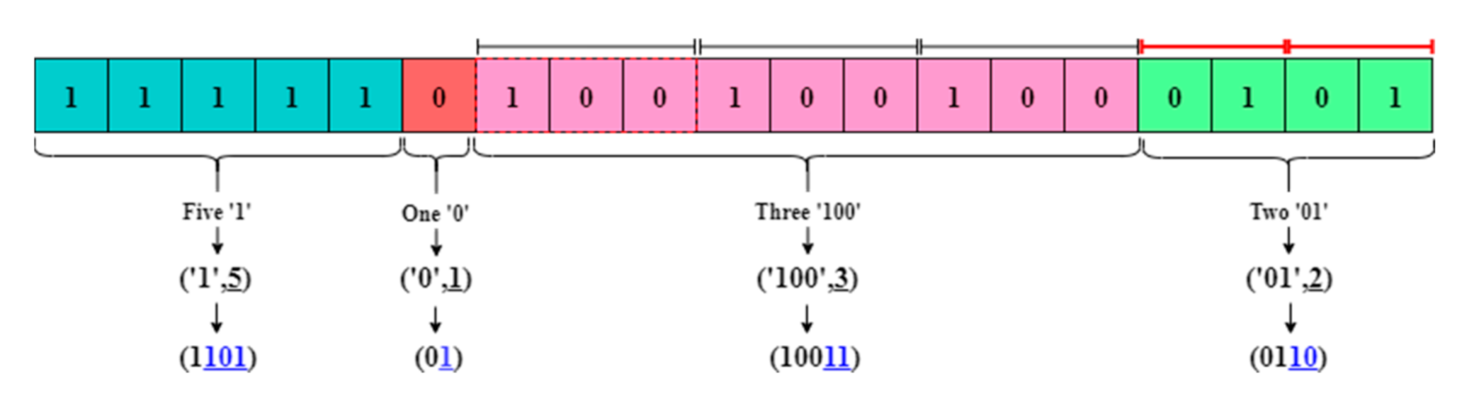
Definition. A combination of one or more selected bits in a binary sequence is denoted by, and the consecutive count occurrences of the in a sequence are denoted by . The and its corresponding can be used to form a two-tuples, denoted as ,). For any given binary sequence, it can be express as in -two-tuples. The and are uniformly represented by binary, and the generated new binary sequence is called two-tuples coding, as shown in Figure 2.
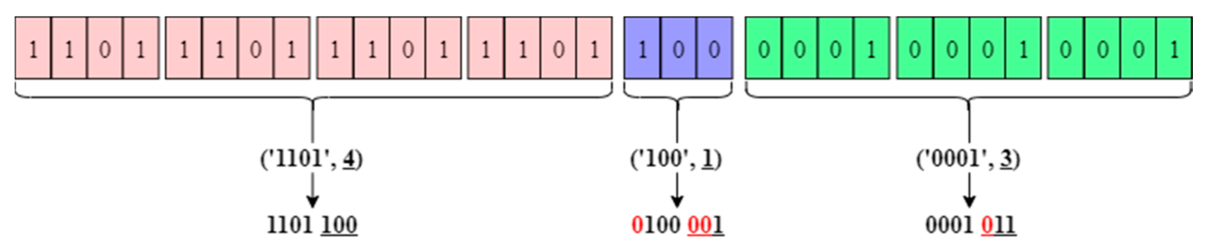
If the bit-length of each two-tuples is different, it is difficult to identify and differentiate Element and Number tuples’ value after continuous coding. A definite value of and must be given before two-tuples coding to restore the encoded two-tuples accurately, such that the bit-length of is denoted by = and the bit-length of is denoted by , where is the bit-length of sequence “”. Then, a sequence must be encoded with and given in advance and uniquely determined. If the bit-length of can not reach the predetermined , it is necessary to supplement redundant bits of at the left of to ensure the uniqueness and definiteness bit-length of and. Thereby, it enables the reducibility properties of two-tuples coding, as illustrated in Figure 3.
Toy Example. Given an original block in binary sequence, , as illustrated in Figure 2, such that , and , run two-tuples coding of by giving the defined value of and , outputs the encoded , denoted by , such that and . The reduced length of coding,, such that . However, in a real-world coding application, an exceptional case may occur when limiting the bit-length of. Let and be the occurred event of the , the possibility of could occur. Given a binary sequence, , and , the shortest two-tuples coding of should be: . However, in the event of and , the value of , resulted in the invalid two-tuples . To address this, it is necessary to disassemble the two-tuples and increase the grouping. The two-tuples of will be encoded as . Then, the validly generated two-tuples of the sequence denoted as and the denotation of two-tuples coding is and . It is noticeable that the value of and can directly affect the coding efficiency. For instance, given the value of and , then , and . Also, the same binary sequence with a different set of values and will result in different lengths of two-tuples coding, illustrated in Figure 4.
3.2. Enhanced Two-Tuples for Image Compression
The intrinsic features of adjacent pixels in the original carrier image exists the identical grayscale values. Conventionally, the binary coding can be used to compress the carrier image, without introducing errors; however, only up to a certain extent, resulted in a low compression rate as the number of identical grayscale values only exists relatively small amount. Considering groups of adjacent pixels in a neighborhood leaves nearly similar grayscale values, especially in decomposing the pixels into the high-level and low-level fragmentations. This study exploited the features of nearly similar grayscale values to compress the carrier image. Thus, it is ensuring the perfect recovery and achieving separable space with a higher embedding rate.
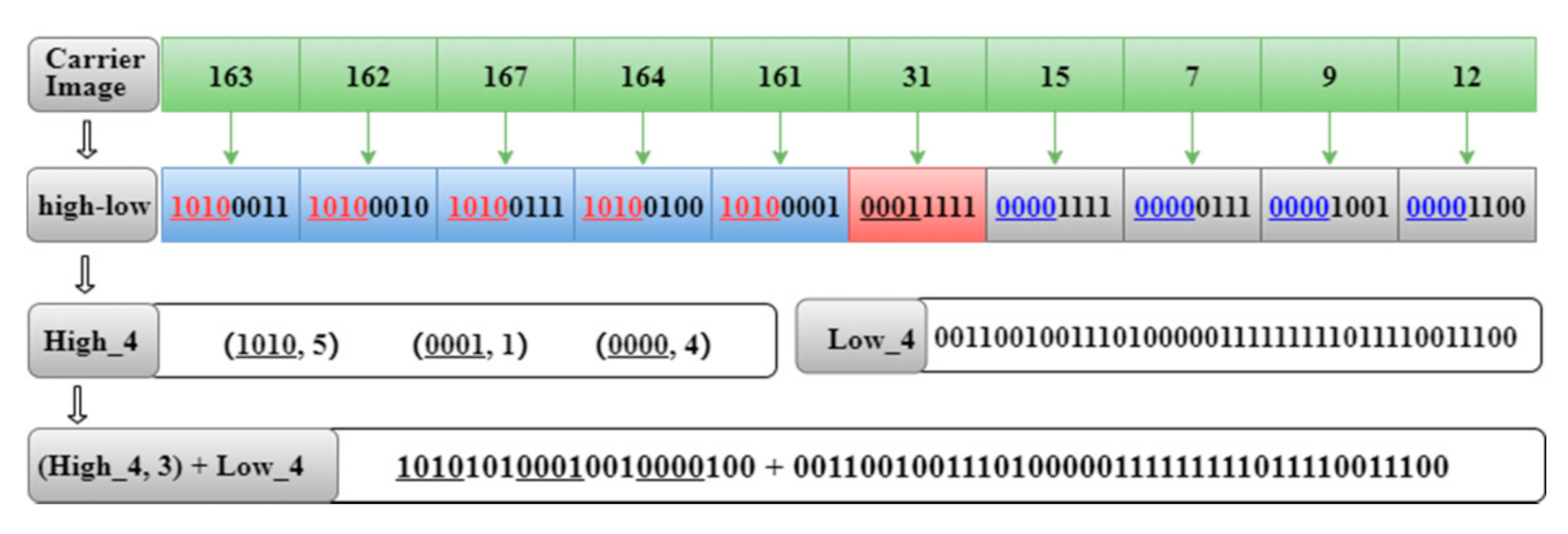
The carrier image generally exists as an array of bytes, and each grayscale pixel typically consists of 8 bits (1 byte). For each pixel value, ], given value in the range of ], there exists an identical high-order 4-bits . Similar to the value in the range of ], it consists of the identical high-order 4-bits . As illustrated in Figure 5, the nearly similar grayscale pixel values of , , , and have the identical high-order 4-bits , while the grayscale pixel values of , , and consist of the identical high-order 4-bits .
The features of nearly similar grayscale values can be further utilized to increase the compression ratio by separating the carrier image’s high-order bits and low-order bits. Let be the high-order -bits of binary pixel coding and be the low-order -bits, in which , given a , a two-tuples encoding of high-level fragmentation is defined as, and low-level fragmentation, . As illustrated in Figure 6, assume that the value of and and the image two-tuples coding is defined as , we encode the part with , and merge the part sequentially.
For a size of the carrier image, let the length of the conventional binary coding,and the length of enhanced two-tuples coding, , if using code, then:
and the reduced bits can be calculated as:
For example, the length of the conventional binary coding of ten adjacent pixels in Figure 6 is bits, and the two-tuples coding used is , then the length of enhanced two-tuples coding is calculated as:
and the reduced bits can be computed as:
3.3. Evaluation of Compression Efficiency
The compression ratio of the same carrier image is evaluated under different values of and to determine the compression efficiency of the enhanced two-tuples coding in Section 3.2. Five standard grayscale carrier images, of size , i.e., Lena, Peppers, Bridge, Zelda and Airfield in Figure 7, are used to evaluate image compression-bit and compression-rate of the proposed method with the related state-of-the-art works. The experiments are configured in Matlab platform version 2018a and performed on a Windows 10 desktop with an AMD Ryzen 5, CPU 2.10 GHz, 8 GB RAM.
When the value of is in the range of and the value of is in the range of , the experimental results of the compression rate of carrier image Lena, Pepper and Zelda images are summarized in Table 1, Table 2 and Table 3, respectively. As can be seen in Table 1, Table 2 and Table 3, the performance of the compression rate is firmly correlated with the value of and . The compression ratio is relatively small, or cannot even be compressed, if the value of and are too small or too high. When the value of and , the compression ratio reaches the optimal state for both Lena and Peppers images, which are 21.91% and 20.74%, as illustrated in Table 1 and Table 2, respectively. Whereas the optimal compression ratio of Zelda image is 28.90% with the value of and . The other data in the table also prove that the two-tuples coding method can effectively compress the carrier image.
As the content owners may choose various carrier images, , with a different set value of and , it will result in a different compression ratio. However, with the conducted experimental data, we infer that when and , the corresponding two-tuples ofhave a relatively high compression ratio, and they can serve as an optimal parameter to achieve optimal compression ratio. To verify this conjecture’s correctness, we have done a lot of experimental tests for different carrier images. The experiments result revealed that most of the carrier images have the maximum compression ratio in the value of and . Therefore, the content owners can choose optimal parameters in the setting value of and to achieve an optimal embedding rate. Of course, through the test, we can obtain and that correspond to the optimal compression ratio for that particular carrier image, . However, it will cause extra workloads to the image encryptor and affect the algorithm’s generality. Therefore, we suggest using these optimal parameters, to achieve the optimal compression ratio of the carrier image in our RDH-EI scheme.
4. Separable Reversible Data Hiding in Encryption Image (RDH-EI) with Two-Tuples Coding
4.1. Coding Structure of the Encrypted Image
Generally, to realize data hiding in the encryption domain, the carrier image, , needs to be encrypted first, and then generate redundant space in the encrypted image to embed additional data. Nonetheless, the encrypted image,, destroys the correlation between image pixels, and the information entropy is close to the maximum. Therefore, it is challenging to generate a sizeable redundant space in the encrypted image,. This is also the main reason for the low embedding rates of the VRAE, RRBE methods. The content owner has a large choice space for the image encryption method; if the content owner can generate a larger redundant space when encrypting the carrier image, then the data hider can directly embed a large amount of additional data, AD in the space reserved by the content owner, which is the advantage of the VRBE method used in this paper. The two-tuples coding method proposed in this paper can solve the problem better. With the two-tuples coding, a large redundancy space can be reserved in the encrypted image, directly during the image encryption process. The proposed RDH-EI scheme with the two-tuples coding method consists of five processes: high-order bits compression with two-tuples coding method, low-order bits combination, vacancy filling, data embedding, and pixel diffusion. The coding structure of the encrypted image, is illustrated in Figure 8.
4.2. Calculate the High-Order Bits and Low-Order Bits of the Image
Setup: Letbe a carrier image of size . The high-order-bits and low-order -bits of each pixel can be obtained by functions bitshift() and mod(), respectively:
where returns shifted to the left by bits, if and , shifts the bits to the left and inserts 0-bits on the right, and, if and , shifts the bits to the right and inserts |k| 0-bits on the left.
For example, if the value of a grayscale pixel is 13 and its corresponding binary value is 00001101, the high-order 6-bits:
Low-order 2-bits:
This implies that if the pixels’ greyscale value is 13, then the high-order 6-bits are 000011, and the remaining low-order 2-bits are 01.
4.3. High-Order Bits Compression with Two-Tuples Coding Method
Step 1: Calculate the high-order -bits of the carrier image, A by using bitshift() function and record it as:
Step 2: Transform into one-dimensional space and double data type by using double() function as defined as follows:
Step 3: Record the value of continuous occurrence of and its continuous occurrence times by using the following find() function as the following:
Starting subscript of each:
Number of consecutive occurrences of :
Step 4: When , the needs to be disassembled, make, the sequence of along the extension is recorded as , and its length is counted as the following:
Step 5: Each of the elements of and its corresponding number are sequentially connected into a new one-dimensional space, by using strcat() function as below:
Step 6: Splits into 8-bit blocks,, such that:
If the last block is less than 8 bits, appends 8- “0 “bits on the right of .
Step 7: Transform to decimal space by using function bin2dec ():
is the second part of the encrypted image , the total of bits is .
4.4. High-Order Bits Compression with Two-Tuples Coding Method
Step 1: Calculate the low-order -bits of the carrier image, with the size of , and record it as:
Step 2: Convert every to a one-dimensional binary space with function dec2bin(), such that:
All the digits of should be equal to, if less then, add ‘0′ in the front of. Then, perform fragmentation by using function cellstr() to partition the into -bits cell, such that:
Step 3: Concatenate scattered into a new continuous one-dimensional binary space, , as the following strcat() function:
Step 4: Change to character type, with the function char() as below:
and group by 8 bits. If the last group is less than 8 bits, append 8-0-bits on the right to obtain the , such that:
Step 5: Convert to decimal sequence by using function bin2dec():
is the first part of the encrypted image, , and the total number of bits is .
4.5. Compressed Redundancy Space-Filling Bits
In this part, we use logistic mapping in a chaotic system to generate random sequences for filling the remaining space of the compressed image. The logistic mapping is described as follows:
where , .
The logistic mapping has the characteristics of certainty, pseudorandomness, nonperiodicity and nonconvergence, the sensitivity of the initial value, unpredictability and fast generation speed, thus ensuring the randomness and security of sequence generation. is obtained by combining the low-order bits in Section 4.4, and is obtained by high-order bits can compression in Section 4.3, the total length of the two sequences is . The remaining space of the image is marked as space, and the total bits of space is , then:
Next, given the initial values and , the sequence is generated, and then is obtained by ,
the random sequence is divided into a group every eight bits and converted to decimal, get the sequence, that is:
is the third part of the encrypted image . Finally, all the pixels of the encrypted image are formed by connecting , and in sequence and these pixels are rewritten into the image with the size of , get the encrypted image .
Next, we use an example illustrated in Figure 9 to demonstrate the coding and compression process. Let the carrier image, , with a size of be given by and , the grayscale values of are represented as (163,162,168,166,164,160,124,126,15,13,8,7,9,5), and set the value of and and generate the fragmentation of and by using formula (1). Firstly, transform all the into a one-dimensional binary space, = {0011001010000110…10010101}. Subsequently, for each 8-bit block of , re-group them into a new pixel in order . Then obtained with seven new pixels are (50,134,118,64,207,135,149), served as the first part of the encrypted image , The generated is positioned at the first pixel to the eighth pixel. Subsequently, apply the proposed two-tuples coding (4,4) to all the bits, output . Then, split binary coding of into 8-bit blocks, . Finally, the with three new pixels are generated as (166,118,6), which are taken as the second part of the image, and is positioned from the ninth pixel to the 11th pixel. Consequently, the 12th to 16th pixels are the compressed redundant space, which can be used for embedding additional data.
4.6. Pixel Diffusion
To further improve the security of the encrypted image, we spread the image in plaintext domain into the ciphertext domain by using pixel diffusion. The pixel diffusion is used to change the image’s statistical characteristics in ciphertext domain and prevent the attacker from obtaining valuable information by comparing the image in plaintext space with the encrypted image in the ciphertext domain.
We still use formula (1) to generate a random sequence, , with a size of , and rewrite it into a pixel diffusion matrix of size:
The image after pixel diffusion is , then:
So far, the whole image encryption process is completed and the final image, with redundant space is obtained. To prevent the data hider destroying the useful information of the carrier image, the content owner needs to let the hider know which part is the redundant space, the starting position of redundant space is as follows:
The content owner can directly select a starting position in the redundant space to pass it to the information inserter or directly replace the last byte of the image with .
4.7. Embedding Additional Data
After receiving the encrypted image, the data hider needs to know the starting position, , of the embeddable space and obtain the embeddable space .
Suppose: Additional data are: , , and the length of additional data is , which should satisfy the following requirements: , by giving the initial value and , a sequence with length and unequal elements is generated by Logistic mapping:
It ends when there are elements in that satisfy the condition, then we use to replace the value of the position in the sequence to embed the additional data to get :
For example: = 1 0 1 1 0 1 0 0 1 0 1 1 1, = 1 0 0 1 1 0 0, , as shown in Figure 10. After data embedding, the encrypted imagewith additional data is obtained.
4.8. Recovery of Carrier Image and Extraction of Additional Data
- Recovery of the Carrier Image
Step 1: Input the password, getand , and get the pixel diffusion matrix by formula (21) and (22), then
Step 2: The first bits of the image are taken as a one-dimensional binary space, and then every -bits of sequence is set a group to get the low-order bits of carrier image, .
Step 3: Starting from the () bits of the encrypted image, , the next bits are arranged into a binary sequence, , and then each bits of the sequenceis taken as a group. Construct two-tuples from parameters and , in each group. Expand according to the value of and and get the sequence .
Step 4: Each bit of sequence is a group, and high-order bits of the image are obtained.
Step 5: The high-order bits and low-order bits are combined in turn to get all the pixels of image , and then the image is accurately restored by rewriting it into an image of size.
- Extracting Additional Data
Step 1: The initial values and are obtained by entering the password. Then the sequence is generated by Equation (3).
Step 2: From the last bytes of image to get , starting from the bit of image , the left bits are arranged into a binary sequence , and the sequence is obtained by finding the value of the corresponding position of sequence in sequence . The computer formula is as follows:
Step 3: By restoring all binaryto the original file format, then the additional data can be extracted accurately. The process of extracting additional data is straightforward and fast.
5. Experimental Results and Analysis
5.1. Embedded Capacity
The embedding capacity depends on the compression ratio of the image. As aforementioned in Section 3.3, the image compression ratio of our RDH-EI scheme depends on: (i) the core parameters and of ; (ii) number of types (), i.e., the total number of types of elements without changing the arrangement order; and (iii) the number of true identities of (), i.e., the real quantity needed to identify the NET. That is, when the number ofconsecutive occurrences exceeds , it needs to be disassembled. Table 4 shows the relevant parameters of Lena greyscale image sized and .
The calculation formula of the maximum redundant space is as follows:
The calculation formula of the compression rate is as follows:
The embedding rate () of additional data is as follows:
5.2. Experimental Results
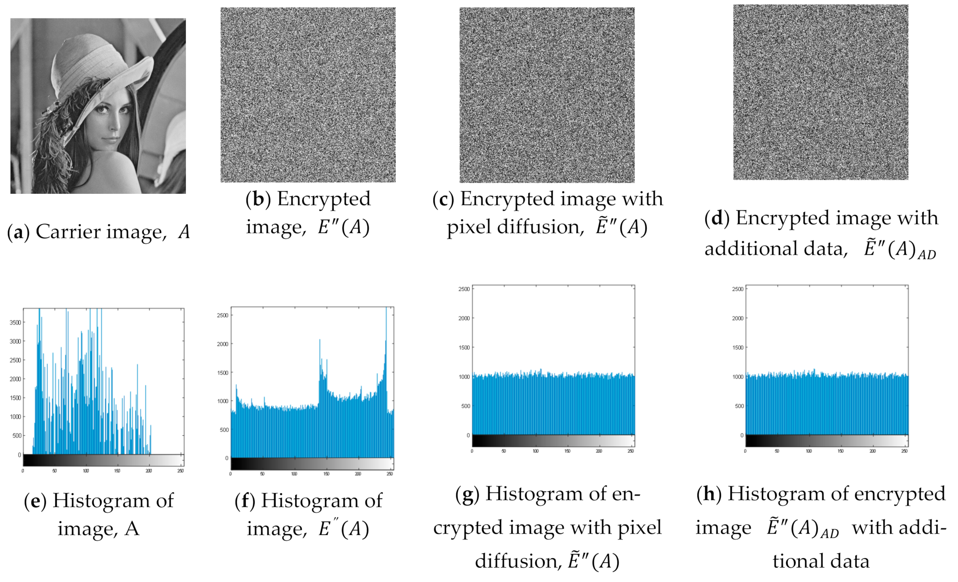
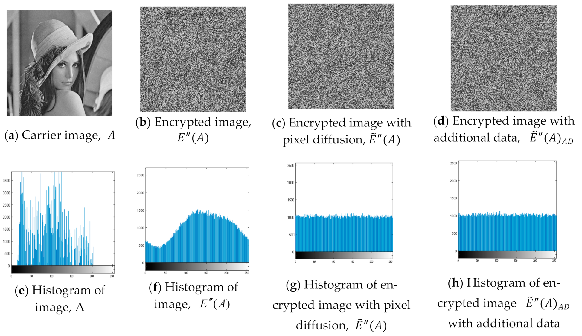
The experiments were conducted on Windows 10 desktop with an AMD Ryzen 5, CPU 2.10 GHz, 8 GB RAM and the selected platform was Matlab version 2018a. The experimental image presented in this paper was a standard greyscale image of Lena size . The embedded data are presented in binary form, and can be text, picture, sound and other multimedia data. To avoid experiment bias, the data that we embedded were randomly generated and presented in a binary sequence. The experimental results are summarized in Figure 11 and Figure 12. Figure 11a illustrates an original Lena image serving as a carrier image, . Figure 11b–d are the encrypted image, without embedded addition data, , the encrypted image with pixel diffusion, , and the encrypted image with additional data, , respectively, with the parameters, . Figure 11e–h show the histograms of encrypted image, without embedded addition data,, the encrypted image with pixel diffusion, , the encrypted image with additional data, respectively. Whereas, Figure 12a–h illustrates the experimental results conducted in a different set of parameters, in which ,. Remarkably, the experimental results of Figure 11e–h and Figure 12e–h revealed that the proposed RDH-EI scheme had achieved a good encryption effect, especially the implemented two-tuples coding method with the pixel diffusion makes the histogram of the encrypted carrier image, tend to be averaged from a random uniform distribution. It can also be further observed in Figure 11 and Figure 12 that the appearance of the original carrier image and its encrypted images, i.e., , and are visually distinct, as well as the distribution of histogram between carrier imageand its encrypted images are divergent. Furthermore, in Figure 11d and Figure 12d, the embedding of additional data has little effect on the histogram of encrypted image, meaning our scheme can effectively resist the statistical analysis and segmentation attack. The proposed RDH-EI scheme, therefore, proves it can effectively change the distribution of pixel values in the ciphertext domain, and achieve a higher security level compared to recent works.
5.3. Correlation Analysis
The correlation coefficient can reflect the degree of correlation between two linear correlation data sets. We can use the correlation coefficient to identify the similarity between two images. The correlation coefficient value is between −1 and 1, and the more the correlation coefficient of the two images tends to 1, the more similar the two images are. The correlation coefficient between the two images, and its encryption versions, ,andare calculated as follows:
where is the covariance of and , are the variances ofand respectively.
Typically, the adjacent pixels of the original carrier image are highly correlated, and the corresponding correlation values are close to 1. The adjacent pixels, on the other hand, are decorrelated after image encryption, and the resulting correlation value decreases. From the data in Table 5 and Table 6, it can be seen that the correlation coefficient of the original carrier image, is close to 1. However, the correlation coefficients of the encrypted image versions, , and are mostly less than 0. These experimental results indicate that our RDH-EI scheme can effectively destroy the correlation of carrier images, thus increasing the complexity of statistical analysis and security attacks.
5.4. Comparison of the Proposed RDH-EI with Related Works
Table 7 summarizes the impactful RDH-EI schemes over the most recent three years. Overall, the RDH-EI schemes constructed based on the blueprint of VRBE method have improved the embedding rate significantly compared to the RDH-EI constructed based on the VRAE and RRBE methods. Notably, the proposed scheme and other VRBE methods [40,41,43] have achieved the highest embedding rate, with on average more than 1.600 bpp, compared to VRAE method [22,27,28,29,30,31,32] and RRBE methods [36,37,38,39], which were limited to the range of [0.120 bpp–0.720 bpp] and [0.180 bpp–1.192 bpp], respectively. Our schemes and VRBE-based RDH-EI schemes can achieve a higher embedding rate without scarifying the image quality, as the Peak Signal-to-Noise Ratio (PSNR) is generally more than 40 dB.
Furthermore, the content owner in our scheme and VRBE-based RDH-EI schemes [40,41,43] generated the embeddable space in advance, therefore removing the solemn duties of the data hider. The data hider focuses only on embedding additional data in the reserved space, without concerning the issues of destroying the original carrier imagewhen embedding additional data into encrypted carrier image. As the process of carrier image encryption and additional data embedding are completely independent, it further implies the separable properties of our RDH-EI scheme and VRAE-based schemes are better than VRAE method and RRBE method.
Subsequently, the nailed-down performance analysis of VRBE-based RDH-EI schemes can compare our scheme with Liu et al. [40], Yi and Zhou [41] and Qin et al. [43]. Table 7 reveals that our scheme and schemes in [40,41,43] are categorized as VRBE method, which intuitively achieves reversible and separable properties. However, different approaches and methods were adopted to maximize the redundant space. Our scheme employs the proposed two-tuples coding method in Section 3 resulted in the highest embedding rate of 1.753 bpp, which are 8.7%, 1.77% and 9.87% higher than Liu et al. [40], Yi and Zhou [41], Qin et al. [43]. The application of sparse block coding in Qin et al. [43] has the lowest embedding rate of 1.580 bpp, compared to the Arnold transform-based encryption method proposed by Liu et al. [40] and parametric binary tree labelling in the works of Yi and Zhou [41], of which the embedding rates are 1.600 bpp and 1.722 bpp respectively.
On the other hand, PSNR is most commonly used to reflect the quality of encryption image reconstruction. Generally, the acceptable PSNR in RDH-EI schemes is higher than 30 dB. The performance of PSNR is close correlated to the embedding rate. The higher the embedding rate, the smaller the PSNR. From Table 7, the PSNR of our scheme scored 45.76 dB and outperformed Liu et al.’s [40] scheme, which only scored 41.49 dB. When benchmarked with Qin et al. [43], who achieved 46.53 dB, our scheme is slightly different at 1.68%. However, our scheme enjoys a higher embedding rate than Qin et al. [43]. Therefore, from four essential elements of performance benchmarking in RDH-EI schemes, i.e., embedding rate, reversibility, separability and image quality (PSNR), the proposed scheme has apparent advantages over recent comparative literature [27,28,29,30,31,32,36,37,38,39,40,41,43].
5.5. Complexity Analysis
In addition to comparisons of the embedded capacity, reversibility, separability, visual quality of different methods, we also analyzed the computing complexity of the recent VRBE methods during the image encrypt and the embedding process. To avoid experiment bias, the time measurement was taken when the embedding rate reached the maximum. Generally, the VRBE method embeds additional data, AD, directly in the reserved space of the encrypted image, resulting in a faster data embedding process than VRAE and RRBE methods. However, different methods in generating the encrypted images with redundant space may affect the computing efficiency, as summarized in Table 8.
Yi et al.’s method [41] took the longest time to reach its maximum embedding with 0.3298 s. The main reason is that their image encryption algorithm is constructed based on a parametric binary tree labelling scheme. Liu et al. [40]’s VRBE method took 0.2581 s as extra time needed to judge each block and record the bit plane used to embed additional data. On the other hand, our scheme and Qin et al.’s method [43] improved computing efficiency more than 50% more Yi et al.’s [41] and Liu et al.’s [40] approaches, which took 0.1264 s and 0.1301 s, respectively. Our scheme and Qin et al.’s [43] scheme applied image coding and LSB method to achieve image encryption and redundant space generation. The performance of the proposed two-tuples coding techniques is relatively closed and comparable to the sparse block coding techniques in Qin et al.’s [43] scheme.
5.6. Security Analysis
The security analysis of RDH-EI is closely related to the performance of image histogram, coefficient correlation and PSNR. The analyzed result and discussion in Section 5.2, Section 5.3 and Section 5.4 revealed that the proposed scheme could achieve a high-security level compared to recent RDH-EI schemes. This section subsequently focuses on analyzing the security of carrier imageand additional data.
For a carrier image,, with the size of , after high-order bits compression, low-order bits recombination, vacancy filling and data embedding, the generated encryption image still in the size of . However, the carrier image information can be determined only during the process of the high-order bits compression and low-order bits recombination, and the scale is . The rest of the encryption processes are not related to the carrier image. As the scale , so it is impossible to obtain all the information of carrier image by using a few pieces of information through puzzle solver and brute-force attack. Moreover, the two-tuples coding completely breaks the structure and encoding mode of the original image pixels, and can resist statistical analysis and differential analysis. Our scheme has strong resistance ability, and it is obviously performing better than VRAE and RRBE methods in securing the carrier image .
For the security of additional data, firstly it is difficult for attackers to accurately obtain the starting position of secret information. Secondly, the embedding position of additional data, is randomly selected from the carrier’s filling-bits part, which is a group of random numbers and has no direct relationship with the carrier image, . The content owner can accurately restore the carrier image and know what the filling-bits part is. However, it is not helpful to extract additional dataas it is challenging to identify which bits belong to additional data in the filling-bits part. Of course, we can encrypt the additional databefore embedding it, which can further improve the security of additional data. The security analysis of the encrypted image and additional data as well as the performance analysis of the image histogram, coefficient correlation and PSNR in Section 5.2, Section 5.3 and Section 5.4, show that our RDH-EI scheme enjoys a higher security level than recent works RDH-EI.
6. Conclusions
This paper presents an RDH-EI scheme with two-tuples coding that aimed to improve the low embedding rate and security level of recent VRBE-based RDH-EI schemes. Our RDH-EI scheme consists of five processes: high-order bits compression with two-tuples coding method, low-order bits combination, vacancy filling, data embedding, and pixel diffusion. Our scheme’s main advantages are: (i) the two-tuples coding method had effectively compressed the high-order bits of the carrier image with an optimal compression ratio of 28.90%, resulting in a larger redundant space to embed more additional data. The proposed two-tuples coding is not limited to the application in the information hiding field; however, it is also an alternative method for lossless compression of the image. (ii) The proposed RDH-EI scheme can improve the embedding rate without scarifying the image quality. Our scheme achieved the highest embedding rate of 1.753 bpp with the PSNR 45.76 dB compared to recent VRBE-based RDH-EI schemes. (iii) The proposed two-tuple coding method achieved computing efficiency almost 50% better than recent VRBE-based RDH-EI schemes and the achievement is comparable to sparse block coding. (iv) Our scheme enjoys a higher security level and can defend against differential analysis and statistical attacks. The correlation coefficients of the encrypted image in our scheme are mostly less than 0, i.e., −0.00024 in the encrypted image’s horizontal direction. The distribution of histogram and the appearance between the carrier image and its encrypted versions are distinct. The two-tuple coding method implemented with pixel diffusion makes the encrypted carrier image histogram appear to be averaged from a random uniform distribution. (v) The proposed RDH-EI scheme satisfies both reversible and separable properties, compared to VRAE and RRBE methods. While the data hider in the recent RDH-EI schemes still suffered from the issues of destroying the original carrier image when embedding additional data, the capability of our scheme in generating the embeddable space by the content owner in advance, our scheme, therefore, has a high generality to be adopted in preserving image privacy in different fields and various applications. Future works will concentrate on optimizing security parameters to further improve the algorithm efficiency. Subsequently, a prototype will be developed to support medical image processing and outsourced cloud storage applications.
Author Contributions
Conceptualization, J.W. and S.F.T.; methodology, J.W.; software, J.W.; validation, J.W. and S.F.T.; formal analysis, J.W. and S.F.T.; investigation, J.W. and S.F.T.; data curation, J.W.; writing—original draft preparation, J.W. and S.F.T.; writing—review and editing, S.F.T.; visualization, J.W.; supervision S.F.T.; project administration S.F.T.; funding acquisition, S.F.T. All authors have read and agreed to the published version of the manuscript.
Funding
This research was supported by the research grant of the UNIVERSITI MALAYSIA SABAH, and MINISTRY OF HIGHER EDUCATION, under grant number FRG0530-2020 and SDK0165-2020, and Young and Middle-aged Teachers’ Ability Improvement Project of Guangxi, grant number 2020KY16021.
Institutional Review Board Statement
Not applicable.
Informed Consent Statement
Not applicable.
Data Availability Statement
All data has been present in main text.
Conflicts of Interest
The authors declare no conflict of interest.
Appendix A

Table A1.
Glossary of acronyms.
| Acronyms | Full Names |
|---|---|
| RDH | Reversible Data Hiding |
| RDH-EI | Reversible Data Hiding in Encryption Image |
| SRDH-EI | Separable Reversible Data Hiding in Encryption Image |
| VRAE | Vacating Room After Encryption |
| RRBE | Reserving Room Before Encryption |
| VRBE | Vacating Room By Encryptio |
| AD | Additional Data |
| ER | Embedding Rate |
| PD | Pixel Diffusion |
| LSB | Least Significant Bits of image |
| PSNR | Peak Signal to Noise Ratio |
Table A2.
Mathematical notations.
| Symbols | Meaning | Symbols | Meaning |
|---|---|---|---|
| Carrier image | High-order -bits value of pixel | ||
| Encrypted image with the method of VRAE | Double data type of | ||
| Encrypted image with the method of RRBE | Continuous occurrence times of | ||
| Encrypted image with the method of VRBE | Low-bits sequential 8-bit binary | ||
| Output of embedding data into the encrypted image of | High-bits sequential 8-bit binary | ||
| Output of embedding data into Encrypted image of | Second part of the encrypted image | ||
| output of embedding data into Encrypted image of | First part of the encrypted image | ||
| Encrypted Image after pixel diffusion of | Third part of the Encrypted image | ||
| A combination of one or more selected bits in a binary sequence | Total bits of space | ||
| Consecutive count of the in a sequence | Length of | ||
| Bit-length of | Additional data | ||
| Bit-length of | A random sequence | ||
| High-order -bits of binary pixel coding | Matrix of sequence | ||
| Low-order -bits of binary pixel coding | A random sequence | ||
| Result of embedding AD in the complement |
References
- Kumar, R.; Chand, S.; Singh, S. A Reversible High Capacity Data Hiding Scheme Using Combinatorial Strategy. Int. J. Multimed. Intell. Secur. 2018, 3, 146–161. [Google Scholar] [CrossRef]
- Kumar, R.; Chand, S.; Singh, S. An Improved Histogram-Shifting-Imitated Reversible Data Hiding Based on HVS Characteristics. Multimed. Tools Appl. 2018, 77, 13445–13457. [Google Scholar] [CrossRef]
- Malik, A.; Sikka, G.; Verma, H.K. A Reversible Data Hiding Scheme for Interpolated Images Based on Pixel Intensity Range. Multimed. Tools Appl. 2020, 2, 1–27. [Google Scholar] [CrossRef]
- Tang, Z.; Nie, H.; Pun, C.; Yao, H.; Yu, C.; Zhang, X. Color Image Reversible Data Hiding with Double-Layer Embedding. IEEE Access 2020, 8, 6915–6926. [Google Scholar] [CrossRef]
- Liu, Y.L.; Qu, X.X.; Xin, G.J. A ROI-based Reversible Data Hiding Scheme in Encrypted Medical Images. J. Vis. Commun. Image Represent. 2016, 39, 51–57. [Google Scholar] [CrossRef]
- Wu, H.T.; Huang, J.W.; Shi, Y.Q. A Reversible Data Hiding Method with Contrast Enhancement for Medical Images. J. Vis. Commun. Image Represent. 2015, 31, 146–153. [Google Scholar] [CrossRef]
- Chen, Y.; Hung, T.; Hsieh, S.; Shiu, C. A New Reversible Data Hiding In Encrypted Image Based on Multi-Secret Sharing and Lightweight Cryptographic Algorithm. IEEE Trans. Inf. Forensics Secur. 2019, 14, 3332–3343. [Google Scholar] [CrossRef]
- Khan, A.N.; Fan, M.Y.; Nazeer, M.I.; Memon, R.A.; Malik, A.; Husain, M.A. An Efficient Separable Reversible Data Hiding Using Paillier Cryptosystem for Preserving Privacy in Cloud Domain. Electronics 2019, 8, 682. [Google Scholar] [CrossRef] [Green Version]
- Zhang, X. Reversible Data Hiding in Encrypted Image. IEEE Signal Process. Lett. 2011, 18, 255–258. [Google Scholar] [CrossRef]
- Parah, S.A.; Ahad, F.; Sheikh, J.A.; Bhat, G.M. Hiding Clinical Information in Medical Images: A New High Capacity and Reversible Data Hiding Technique. J. Biomed. Inform. 2017, 66, 214–230. [Google Scholar] [CrossRef]
- Wu, D.; Xu, R.X. Reversible Data Hiding in the Encrypted Domain for Medical Image Security. Basic Clin. Pharmacol. Toxicol. 2019, 125, 225–226. [Google Scholar]
- Ke, G.; Wang, H.; Zhou, S.; Zhang, H. Encryption of Medical Image with Most Significant Bit and High Capacity in Piecewise Linear Chaos Graphics. Measurement 2019, 135, 385–391. [Google Scholar] [CrossRef]
- Shen, W.T.; Qin, J.; Yu, J.; Hao, R.; Hu, J. Enabling Identity-Based Integrity Auditing and Data Sharing with Sensitive Information Hiding for secure cloud storage. IEEE Trans. Inf. Forensics Secur. 2019, 12, 331–346. [Google Scholar] [CrossRef]
- Xiong, L.Z.; Shi, Y.Q. On the Privacy-Preserving Outsourcing Scheme of Reversible Data Hiding over Encrypted Image Data in Cloud Computing. Comput. Mater. Continua 2018, 55, 523–539. [Google Scholar] [CrossRef]
- Yang, Y.; Xiao, X.; Cai, X.; Zhang, W. A Secure and Privacy-Preserving Technique Based on Contrast-Enhancement Reversible Data Hiding and Plaintext Encryption for Medical Images. IEEE Signal. Process. Lett. 2020, 27, 256–260. [Google Scholar] [CrossRef]
- Yuan, G.; Hao, Q. Digital Watermarking Secure Scheme for Remote Sensing Image Protection. China Commun. 2020, 17, 88–98. [Google Scholar] [CrossRef]
- Wu, G.; Lee, C. Framework for cloud database protection by using reversible data hiding methods. In Proceedings of the IEEE International Conference on Consumer Electronics, Ilan, Taiwan, 20–22 May 2019; pp. 1–2. [Google Scholar] [CrossRef]
- Iqbal, M.M.; Khadam, U.; Han, K.J.; Han, J.; Jabbar, S. A Robust Digital Watermarking Algorithm for Text Document Copyright Protection Based on Feature Coding. In Proceedings of the 15th International Wireless Communications & Mobile Computing Conference (IWCMC), Tangier, Morocco, 24–28 June 2019; pp. 1940–1945. [Google Scholar] [CrossRef]
- Liao, X.; Shu, C.W. Reversible Data Hiding in Encrypted Images Based on Absolute Mean Difference of Multiple Neighboring Pixels. J. Vis. Commun. Image Represent. 2015, 28, 21–27. [Google Scholar] [CrossRef]
- Hong, W.; Chen, T.S.; Wu, H.Y. An Improved Reversible Data Hiding in Encrypted Images Using Side Match. IEEE Signal. Process. Lett. 2012, 199–202. [Google Scholar] [CrossRef]
- Qin, C.; Zhang, X.P. Effective Reversible Data Hiding in Encrypted Image with Privacy Protection for Image Conten. J. Vis. Commun. Image Represent. 2015, 31, 154–164. [Google Scholar] [CrossRef]
- Wang, Y.M.; Cai, Z.C.; He, W.G. A New High Capacity Separable Reversible Data Hiding in Encrypted Images Based on Block Selection And Block-Level Encryption. IEEE Access 2019, 7, 175671–175680. [Google Scholar] [CrossRef]
- Zhang, X.P. Separable Reversible Data Hiding in Encrypted Imag. IEEE Trans. Inf. Forensics Secur. 2012, 7, 826–832. [Google Scholar] [CrossRef]
- Xu, D.W.; Wang, R.D. Separable and Error-Free Reversible Data Hiding in Encrypted Images. Signal. Process. 2016, 123, 9–21. [Google Scholar] [CrossRef]
- Agrawal, S.; Kumar, M. Mean Value Based Reversible Data Hiding in Encrypted Images. Optik 2017, 130, 922–934. [Google Scholar] [CrossRef]
- Singh, P.; Raman, B. Reversible Data Hiding for Rightful Ownership Assertion of Images In Encrypted Domain Over Cloud. Aeu-Int. J. Electron. Commun. 2017, 76, 18–35. [Google Scholar] [CrossRef]
- Qin, C.; Zhang, W.; Cao, F.; Zhang, X.; Chang, C.C. Separable Reversible Data Hiding in Encrypted Images Via Adaptive Embedding Strategy with Block Selection. Signal. Process. 2017, 153, 109–122. [Google Scholar] [CrossRef]
- Zhang, W.; Kong, P.; Yao, H.; Hu, Y.C.; Cao, F. Real-Time Reversible Data Hiding in Encrypted Images Based on Hybrid Embedding Mechanism. J. Real-Time Image Process. 2019, 16, 697–708. [Google Scholar] [CrossRef]
- Yi, S.; Zhou, Y.C.; Hua, Z.Y. Reversible Data Hiding in Encrypted Images using Adaptive Block-Level Prediction-Error Expansion. Signal. Process. Image Commun. 2018, 64, 78–88. [Google Scholar] [CrossRef]
- Di, F.Q.; Huang, F.J.; Zhang, M.Q. Reversible Data Hiding in Encrypted Images with High Capacity by Bitplane Operations and Adaptive Embedding. Multimed. Tools Appl. 2018, 7, 20917–20935. [Google Scholar] [CrossRef]
- Yu, C.; Zhang, X.; Tang, Z.; Xie, X. Separable and Error-Free Reversible Data Hiding in Encrypted Image Based on Two-Layer Pixel Errors. IEEE Access 2018, 6, 76956–76969. [Google Scholar] [CrossRef]
- Xu, D.W.; Su, S.B. Separable Reversible Data Hiding in Encrypted Images Based on Difference Histogram Modification. Secur. Commun. Netw. 2019, 6, 1–14. [Google Scholar] [CrossRef]
- Cao, X.; Du, L.; Wei, M.D.; Guo, X. High Capacity Reversible Data Hiding in Encrypted Images by Patch-Level Sparse Representation. IEEE Trans. Cybern. 2016, 46, 1132–1143. [Google Scholar] [CrossRef]
- Han, X.; Qian, Z.X.; Feng, G.R.; Zhang, X.P. Reversible Data Hiding in Encrypted Images Based on Image Interpolation. Int. J. Digit. Crime Forensics 2014, 6, 16–29. [Google Scholar] [CrossRef]
- Qian, Z.X.; Zhang, X.P.; Feng, G.R. Reversible Data Hiding in Encrypted Images Based on Progressive Recovery. IEEE Signal. Process. Lett. 2016, 23, 1672–1676. [Google Scholar] [CrossRef]
- Li, Q.; Yan, B.; Li, H. Separable Reversible Data Hiding in Encrypted Images with Improved Security and Capacity. Multimed. Tools Appl. 2018, 77, 30749–30768. [Google Scholar] [CrossRef]
- Wu, H.B.; Li, F.Y.; Qin, C.; Wei, W.M. Separable Reversible Data Hiding in Encrypted Images Based on Scalable Blocks. Multimed. Tools Appl. 2019, 78, 25349–25372. [Google Scholar] [CrossRef]
- Nasrullah, N.; Sang, J.; Mateen, M.; Akbar, M.A.; Xiang, H.; Xia, X.F. Reversible Data Hiding in Compressed and Encrypted Images by using Kd-tree. Multimed. Tools Appl. 2019, 78, 17535–17554. [Google Scholar] [CrossRef]
- Yu, M.J.; Liu, Y.C.; Sun, H.; Yao, H.; Qiao, T. Adaptive and Separable Multiary Reversible Data Hiding in Encryption Domain. Eurasip J. Image Video Process. 2020, 1–15. [Google Scholar] [CrossRef]
- Liu, Z.L.; Pun, C.M. Reversible Data-Hiding in Encrypted Images by Redundant Space Transfer. Inf. Sci. 2018, 433, 188–203. [Google Scholar] [CrossRef]
- Yi, S.; Zhou, Y.C. Separable and Reversible Data Hiding in Encrypted Images Using Parametric Binary Tree Labeling. IEEE Trans. Multimed. 2019, 21, 51–64. [Google Scholar] [CrossRef]
- Tang, Z.J.; Xu, S.J.; Yao, H.; Qin, C.; Zhang, X.Q. Reversible Data Hiding with Differential Compression in Encrypted Image. Multimed. Tools Appl. 2019, 78, 9691–9715. [Google Scholar] [CrossRef]
- Qin, C.; Qian, X.K.; Hong, W.; Zhang, X.P. An Efficient Coding Scheme for Reversible Data Hiding In Encrypted Image With Redundancy Transfer. Inf. Sci. 2019, 487, 176–192. [Google Scholar] [CrossRef]
Figure 1.
The framework of VRAE, RRBE and VRBE in RDH-EI.

Figure 2.
Schematic diagram of the two-tuples coding method.

Figure 3.
The padding of two-tuples coding for and (the bit highlighted in red is a supplemented-bit).
Figure 3.
The padding of two-tuples coding for and (the bit highlighted in red is a supplemented-bit).

Figure 4.
Two-tuples coding under different and conditions.
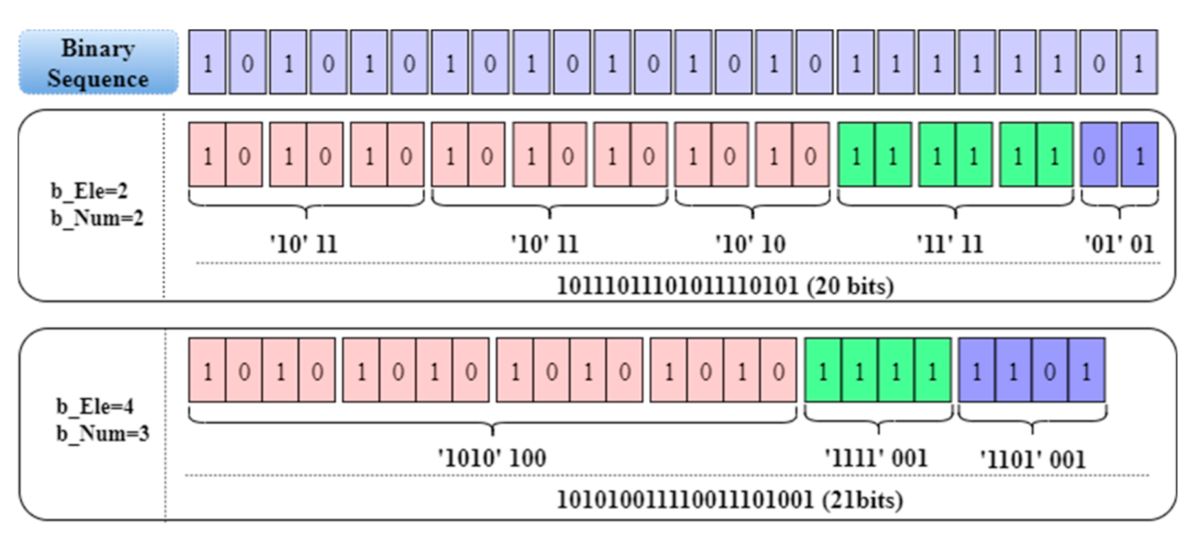
Figure 5.
Pixels with similar grayscale values have the same high-bits.
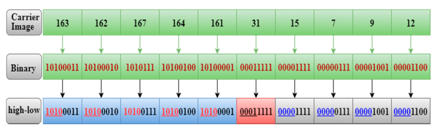
Figure 6.
Schematic diagram of image two-tuples coding.

Figure 7.
Five standard test images.
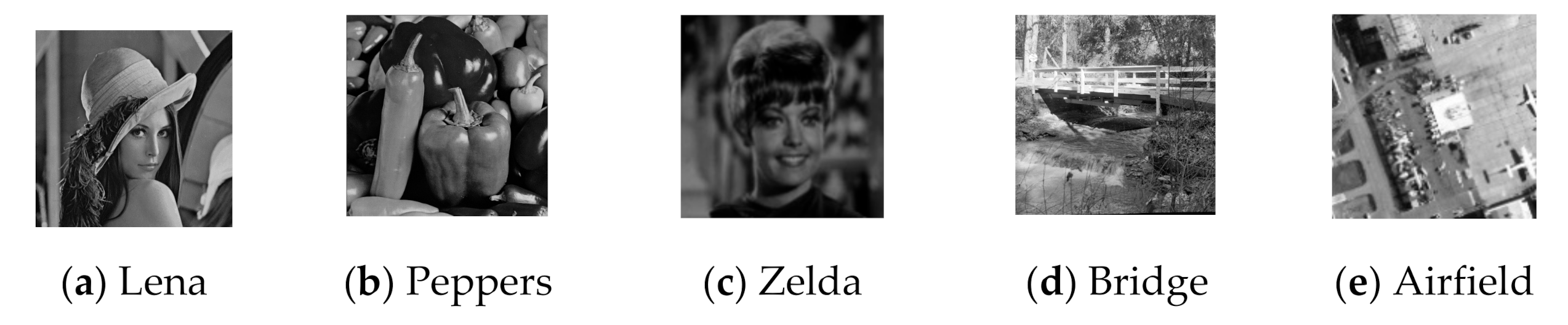
Figure 8.
Coding structure of the encrypted image.
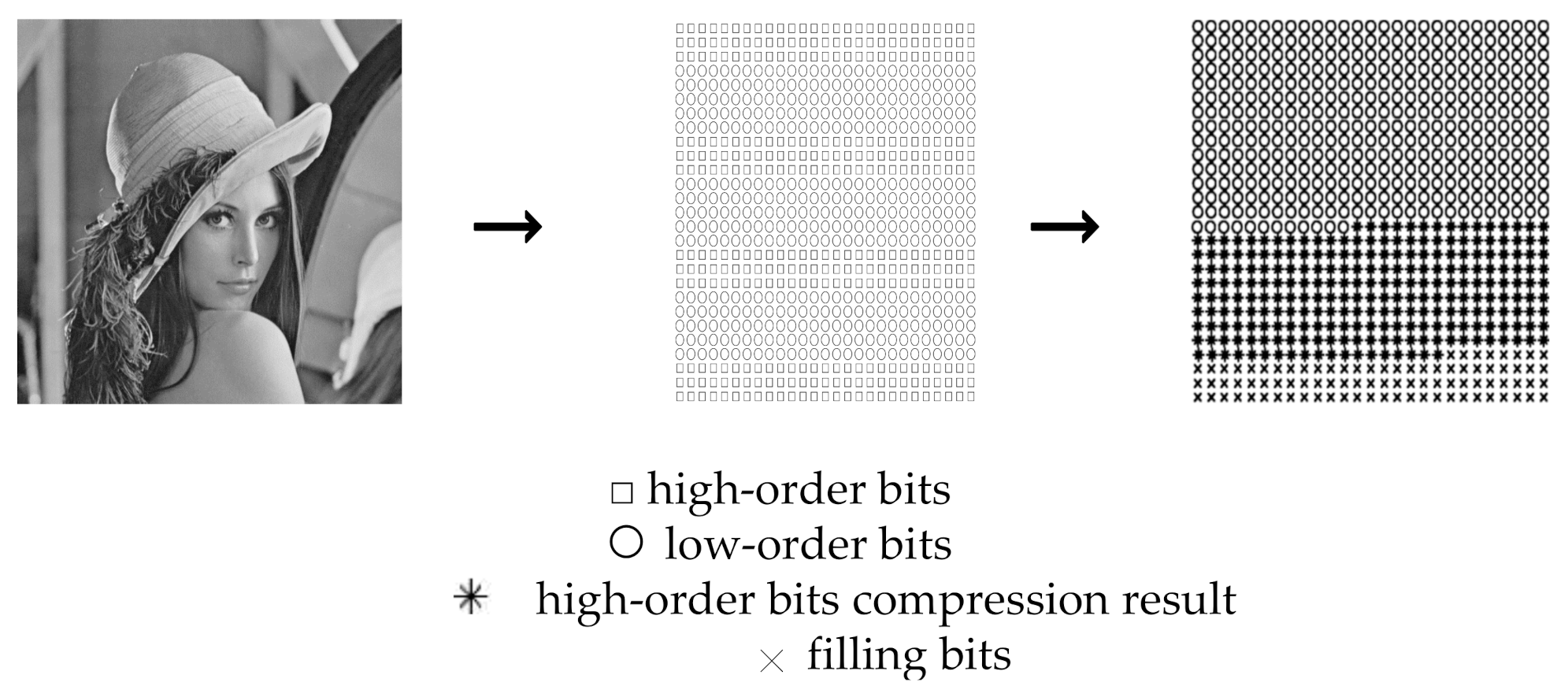
Figure 9.
Examples of two-tuples coding and image encrypting (, ).
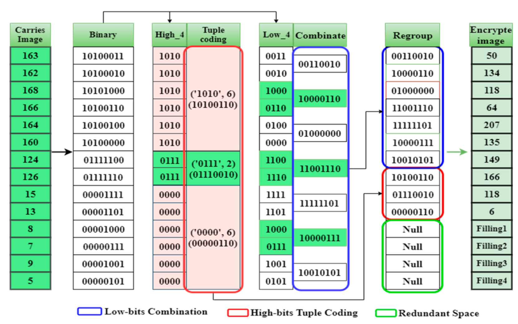
Figure 10.
The method of embedding additional data.

Figure 11.
Experimental results of the proposed RDH-EI scheme. (, , ,).

Figure 12.
Experimental results of the proposed scheme (, ,,).

Table 1.
Lena image compression-bit and compression-rate of different (bit, %).
| 1 | 2 | 3 | 4 | 5 | 6 | |
| 1 | ─ | ─ | ─ | ─ | ─ | ─ |
| 2 | ─ | 139,552 (6.65%) | 265,377 (12.65%) | 318,316 (15.18%) | 284,121 (13.55%) | 126,856 (6.05%) |
| 3 | 87,092 (4.15%) | 273,113 (13.02%) | 415,146 (19.80%) | 439,051 (20.94%) | 328,544 (15.67%) | 43,008 (2.05%) |
| 4 | 136,639 (6.52%) | 326,636 (15.58%) | 459,462 (21.91%) | 436,696 (20.82%) | 253,544 (12.09%) | ─ |
| 5 | 160,366 (7.65%) | 341,826 (16.30%) | 458,072 (21.84%) | 388,444 (18.52%) | 145,080 (6.92%) | ─ |
| 6 | 168,505 (8.03%) | 338,328 (16.13%) | 435,315 (20.76%) | 323,026 (15.40%) | 29,275 (1.40%) | ─ |
| 7 | 168,176 (8.02%) | 324,695 (15.48%) | 402,642 (19.20%) | 251,934 (12.01%) | ─ | ─ |
Table 2.
Peppers image compression-bit and compression-rate of different (bit, %).
| 1 | 2 | 3 | 4 | 5 | 6 | |
| 1 | ─ | ─ | ─ | ─ | ─ | ─ |
| 2 | ─ | 140,500 (6.70%) | 252,092 (12.02%) | 304,282 (14.51%) | 243,178 (11.60%) | 70,016 (3.34%) |
| 3 | 87,584 (4.18%) | 277,093 (13.21%) | 395,694 (18.87%) | 420,704 (20.06%) | 264,672 (12.62%) | ─ |
| 4 | 138,919 (6.62%) | 334,664 (15.96%) | 434,857 (20.74%) | 413,984 (19.74%) | 175,910 (8.39%) | ─ |
| 5 | 164,278 (7.83%) | 355,805 (16.97%) | 427,880 (20.40%) | 362,605 (17.29%) | 59,650 (2.84%) | ─ |
| 6 | 174,581 (8.32%) | 356,520 (17.00%) | 400,449 (19.09%) | 294,806 (14.06%) | ─ | ─ |
| 7 | 174,800 (8.34%) | 346,232 (16.51%) | 362,622 (17.29%) | 221,068 (10.54%) | ─ | ─ |
Table 3.
Zelda image compression-bit and compression-rate of different (bit, %).
| 1 | 2 | 3 | 4 | 5 | 6 | |
| 1 | ─ | ─ | ─ | ─ | ─ | ─ |
| 2 | ─ | 158,592 (7.56%) | 300,232 (14.32%) | 394,474 (18.81%) | 395,974 (18.88%) | 253,264 (12.08%) |
| 3 | 106,816 (5.09%) | 309,153 (14.74%) | 478,344 (22.81%) | 569,111 (27.14%) | 505,184 (24.09%) | 219,084 (10.45%) |
| 4 | 166,594 (7.94%) | 380,102 (18.12%) | 546,885 (26.08%) | 606,008 (28.90%) | 464,819 (22.16%) | 84,974 (4.05%) |
| 5 | 200,248 (9.55%) | 413,639 (19.72%) | 566,248 (27.00%) | 585,454 (27.92%) | 382,480 (18.24%) | ─ |
| 6 | 219,367 (10.46%) | 427,688 (20.39%) | 559,452 (26.68%) | 543,086 (25.90%) | 290,976 (13.87%) | ─ |
| 7 | 229,792 (10.96%) | 428,546 (20.43%) | 540,782 (25.79%) | 494,330 (23.57%) | 198,548 (9.47%) | ─ |
Table 4.
When , the parameters that affect the embedded capacity (Lena).
| 1 | 1 | 11,000 | 262,144 | ─ | ─ |
| 2 | 2 | 21,740 | 96,184 | 139,552 | 6.65% |
| 3 | 3 | 38,239 | 61,881 | 415,146 | 19.89% |
| 4 | 4 | 72,415 | 76,485 | 436,696 | 20.82% |
| 5 | 5 | 116,494 | 116,564 | 145,080 | 6.92% |
| 6 | 6 | 169,042 | 169,067 | ─ | ─ |
Table 5.
Image adjacent pixel correlation (Figure 11a–d).
Table 5.
Image adjacent pixel correlation (Figure 11a–d).
| Correlation | Carrier Image, (a) | Encrypted Image, (b) | Encrypted Image with Pixel Diffusion, (c) | Encrypted Image with Additional Data, (d) |
| Horizontal direction | 0.9848 | −0.0369 | 0.0032 | 0.0028 |
| Horizontal direction | 0.9726 | 0.0037 | −0.00068 | −0.00024 |
| Diagonal direction | 0.9592 | 0.0018 | −0.00067 | −0.0003 |
Table 6.
Image adjacent pixel correlation (Figure 12a–d).
Table 6.
Image adjacent pixel correlation (Figure 12a–d).
| Correlation | Carrier Image, (a) | Encrypted Image, (b) | Encrypted Image with Pixel Diffusion, (c) | Encrypted Image with Additional Data, (d) |
| Horizontal direction | 0.9848 | −0.0029 | −0.0046 | −0.0041 |
| Horizontal direction | 0.9726 | −0.0008 | −0.0014 | −0.0011 |
| Diagonal direction | 0.9592 | −0.0006 | −0.0135 | −0.0146 |
Table 7.
Encryption performance comparison of the proposed algorithm with several related works.
| Scheme | Perfect Recovery | Separable | Maximum ER (bpp) | PSNR (dB) | Main Means | Category | Published Year |
| Qin [27] | Yes | Yes | 0.032 | 41.50 | Compressing LSBs | VRAE | 2018 |
| Yi [29] | Yes | Yes | 0.500 | 39.86 | Prediction-error expansion | VRAE | 2018 |
| Di [30] | Yes | Yes | 0.720 | 26.50 | Bit plane decomposition | VRAE | 2018 |
| Yu [31] | Yes | Yes | 0.500 | 36.50 | Modification Histogram | VRAE | 2018 |
| Zhang [28] | Yes | Yes | 0.186 | 44.50 | Divides blocks, stream cipher and permutation | VRAE | 2019 |
| Xu [32] | Yes | Yes | 0.541 | 40.94 | Prediction error, Modification Histogram | VRAE | 2019 |
| Wang [22] | No | Yes | 0.120 | - | Flipping LSBs | VRAE | 2019 |
| Li [36] | Yes | Yes | 0.858 | 35.73 | Prediction errors, Stream cipher | RRBE | 2018 |
| Wu [37] | Yes | Yes | 1.192 | 47.93 | Divides blocks, Stream cipher | RRBE | 2019 |
| Nasrullah [38] | Yes | Yes | 0.180 | 39.85 | Wavelet transform, High dimensional Kd-tree | RRBE | 2019 |
| Yu [39] | Yes | Yes | 0.352 | 50.24 | Prediction errors | RRBE | 2020 |
| Liu [40] | Yes | Yes | 1.600 | 41.49 | Arnold transform-based encryption method | VRBE | 2018 |
| Yi [41] | Yes | Yes | 1.722 | - | Parametric binary tree labeling | VRBE | 2019 |
| Qin [43] | Yes | Yes | 1.580 | 46.53 | Sparse block coding | VRBE | 2019 |
| Proposed Scheme | Yes | Yes | 1.753 | 45.76 | Two-tuples coding | VRBE |
Table 8.
Comparison of computing complexity of the recent VRBE methods.
| Test Image (Seconds) | Liu [40] | Yi [41] | Qin [43] | Proposed |
| Lena | 0.2854 | 0.3265 | 0.1255 | 0.1385 |
| Peppers | 0.2257 | 0.3133 | 0.1377 | 0.1433 |
| Zelda | 0.2344 | 0.3658 | 0.1164 | 0.1066 |
| Bridge | 0.2758 | 0.3142 | 0.1287 | 0.1249 |
| Airfield | 0.2691 | 0.3296 | 0.1238 | 0.1372 |
| Average | 0.2581 | 0.3298 | 0.1264 | 0.1301 |
Publisher’s Note: MDPI stays neutral with regard to jurisdictional claims in published maps and institutional affiliations. |
© 2021 by the authors. Licensee MDPI, Basel, Switzerland. This article is an open access article distributed under the terms and conditions of the Creative Commons Attribution (CC BY) license (https://creativecommons.org/licenses/by/4.0/).
Share and Cite
MDPI and ACS Style
Wang, J.; Tan, S.F. Separable Reversible Data Hiding in Encryption Image with Two-Tuples Coding. Computers 2021, 10, 86. https://0-doi-org.brum.beds.ac.uk/10.3390/computers10070086
AMA Style
Wang J, Tan SF. Separable Reversible Data Hiding in Encryption Image with Two-Tuples Coding. Computers. 2021; 10(7):86. https://0-doi-org.brum.beds.ac.uk/10.3390/computers10070086
Chicago/Turabian StyleWang, Jijun, and Soo Fun Tan. 2021. "Separable Reversible Data Hiding in Encryption Image with Two-Tuples Coding" Computers 10, no. 7: 86. https://0-doi-org.brum.beds.ac.uk/10.3390/computers10070086
Note that from the first issue of 2016, this journal uses article numbers instead of page numbers. See further details here.