1. Introduction
Rapid progress in the field of microelectronics, nanotechnology, telecommunications and software engineering has opened unique opportunities for information-oriented systems developers to reach a new level of complexity of the created systems and has led to the emergence of new classes of systems with a fundamentally new level of functionality.
Modern complex systems usually include a big number of elements, but the complexity of the system can be determined not only by the number of elements, but also by the number of element types, the number of hierarchy levels, and the stability of the structure and behavior. The number of internal states can be considered as the universal measure of functional complexity (complexity of behavior). The complexity of the behavior can also be defined in terms of the number and complexity of the implemented functions. One can define two types of complexity: internal and external complexity. Internal complexity is the complexity of the system itself, and external complexity can be estimated by the number and complexity of the system external links [
1].
Almost all large-scale systems have the property of variability in structure and behavior, such systems are mostly distributed systems. Various virtualization mechanisms are widely used in their construction. The implementation of the variability of the structure and cognitive behavior leads to the need to increase the share of the software component, which requires the inclusion of increasingly powerful information processing and storage tools for processing large volumes of information.
In the operation of any information-oriented system, there is always a data acquisition (DA) procedure in one form or another, but the purposes of DA can be different: collecting data on the state of the system itself in order to realize self-* functions, collecting data in order to provide data, information and knowledge (DIK) to stakeholders in the required form, collecting data in order to implement management procedures both at the local and global levels.
As systems become more complex, the task of DA is no longer trivial.
The article consists of 12 sections. In
Section 2, typical properties of modern information-oriented systems are analyzed. In
Section 3, DA problems for large scale distributed systems are discussed. In
Section 4, the scope of the study is presented. In
Section 5, the suggested approach is described. In
Section 6, the conceptual model of the DA is presented.
Section 7 contains a description of the multilevel structural and behavioral models.
Section 8 considers the problem of the model automatic generation.
Section 9 deals with the implementation of the DA procedure using policies and contexts. In
Section 10, DAS typical architectural solutions are discussed. In
Section 11, the use-case description is given.
Section 12 contains conclusions.
2. Typical Properties of Modern Information-Oriented Systems
Intelligent systems include software intensive systems (SwIS). Intelligent systems include both systems that can implement some kind of human-like behavior, and systems that use intelligent technologies, primarily technologies based on knowledge [
2].
It is necessary to take into account that all intelligent systems, including systems that implement the ambient intelligence (AmI) paradigm [
3], are SwIS [
4]. Modern intelligent systems are adaptive systems as their structure and/or behavior can change over time. Many modern man-made systems can be classified as large and (or) complex systems. Almost all systems are distributed systems.
Big, large scale and smart data. The increase of the systems size and performance leads to the well-known big data problem [
5], which consists of the fact that large systems produce huge amounts of data due to following factors: their size, active interaction with the external environment and the presence of powerful computers. That leads to several problems: (i) where to store data, (ii) what the form is to be used to store it, and (iii) how quickly the data in a distributed storage with limited bandwidth of communication channels can be found.
The problem of storing big data can be solved by using cloud storage which can store almost unlimited amounts of data. The main problem is the limited bandwidth of the communication channels. As a solution of this problem, the paradigm of edge and cloud computing was proposed [
6,
7,
8,
9]. This approach partly solves the problem of limited bandwidth of communication channels, but significantly complicates the procedure for managing the systems.
Thus, it can be argued that the distinctive features of modern systems are the following: (i) a new level of complexity, (ii) a new level of heterogeneity, which is expressed in the fact that systems are built from elements of different physical nature and includes in addition to information components, electromechanical, mechanical subsystems, production and technological processes, natural systems, biological systems and people. This leads to the emergence of new classes of systems such as cyber-physical (CPS), and socio-cybernetic systems, etc. [
10,
11,
12,
13].
Nowadays, it is almost impossible to find a complex system based on a single paradigm or technology. Typically, different paradigms and technologies are used on different levels. Thus, it is possible to talk not only about the convergence of technologies, but also about the convergence of paradigms. In this regard, integration of paradigms and technologies are of increasing interest.
3. DA Problems in Large Scale Distributed AmI CPS
The task of DA is one of the key tasks for many classes of SwIS. Sometimes this task appears as one of the subtasks; sometimes this is a final goal. When there are a number of stakeholders with different concerns, the problem of forming data presentation takes place.
In this case, it is necessary to have actual information about the structure of the ObS and the structure of the business processes (BP) running in it before collecting data. If the system is large and works with big data, then this problem is a smart data problem [
14].
Currently, various approaches and tools are used to solve DA problems. To solve the problem of DA about the structure, approaches and tools based on the simple network management protocol are usually used, and BP monitoring tools are used to collect data about the behavior of ObS, but practically all existing methodologies and tools are oriented on working with ObS with stable structures.
4. The Scope of the Study
Fog computing (FC) is one of the widely used platforms for building CPS [
6]. Based on this, the authors consider the problem of building data acquisition systems (DAS) for realizing DA procedures in large scale AmI CPS with dynamic structure and behavior built on fog computing (FC) platforms as a scope of DA problem.
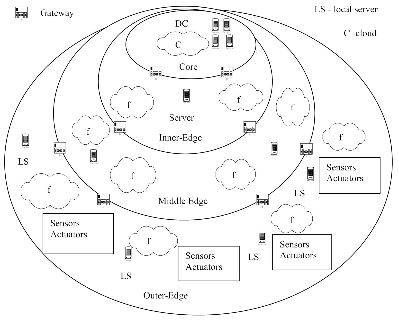
Let us consider the typical structure of the FC platform and deployment of software modules in it. This structure is considered in this article as a generalized structure of a modern distributed AmI CPS. From building DAS point of view, systems built on FC platforms can be conceded as an observable system (ObS) on the one hand, and as a platform for building DAS on the other hand. The generalized structure of the FC platform is shown in
Figure 1. The platform is a three-layer structure that contains the following layers (levels): core, inner layer, middle layer, and external layer.
The individual layers are connected by gateways.
The inner layer is the core of the system, which includes computing resources and data networks on the level of a country, region, metropolis, global aria networks (GAN), and metropolitan area networks (MAN). Data centers (DC) act as a resource. This layer acts primarily as an infrastructure for local networks (LAN) integration and as a service provider. It represents a classic cloud computing environment [
15].
The middle layer is the FC layer. This layer hosts servers that implement local storage functions, typically using mechanisms known as cloudlets, and local data centers to implement processing-related functions. LAN and campus networks (CAN) are used to connect individual elements at this level. In addition, various types of cellular networks (macrocell, microcell, picocell, femtocell) are widely used [
6]. At the middle level, as a rule, different versions of Linux are used as the operating system (OS).
The external layer is formed by devices. This is the level where Internet of things (IoT) systems operate. Sometimes it is also called as the mist layer [
6]. At this level, there are three main types of devices: endpoints (sensors and actuators), embedded controllers, and IP gateways.
Sensors and actuators are usually controlled by microcontrollers that have limited computing performance and often run-on batteries. A typical example is a single-chip Atmel Atmega 328p controller, which is used as the CPU of the popular Arduino Uno Rev3 kit. This controller operates at frequency of 20 MHz and has flash memory of only 32 kB. It should be noted that since IoT systems are actively used as low-price systems, extremely cheap controllers will continue to be used in the foreseeable future. As an OS at the lower level, rather weak operating systems like Contiki and Tiny OS are usually used to control sensors and actuators [
16].
At the lower level, there is usually a certain number of interconnected processors built into various devices and equipment that have significant computing performance. Embedded processors are usually RISC processors, most often ARM processors. These may be smart phones running Android OS. Embedded devices usually have built-in network support (Wi-Fi, Bluetooth). IP routers are used to realize interaction between the end devices and the middle layer, since at the lower level the IP protocol is not used to save energy. Such protocols as Bluetooth Low Energy, Zig Bee or Z-Wave are used most often [
6,
11,
16,
17,
18,
19].
Currently, both commercial and free platforms for building FC systems are available. The platforms as Open Stack++ [
20], Apache Edgent [
21] previously known as Quarks, which usually represent platforms that use Linux and Android OS can be mentioned. Apache Edgent can transfer processing from the cloud to the fog and back.
Developed by Carnegie Mellon University, Open Stack++ framework is focused on working with virtual machines on x86 platforms. However, it should be noted that recently the use of container-type virtualization has become more popular among SwIS developers using containers such as Docker Containers Engine [
22]. WSO2-IoT Server [
6] as an integration platform allows organize effective interaction with various IoT devices such as Arduino Uno, Raspberry Pi, Android OS devices, iOS devices, Windows 10 IoT Core devices, etc. In addition, it is possible to maintain work with data streams in real time. Interaction with clouds is carried out using the message queuing telemetry transport and extensible messaging and presence protocols [
6].
Recently, the Linux Foundation Project opened a new project Edge X Foundry [
23], which aims to create a Software Development Kit framework for FC platforms which is focused on the transition from the paradigm of connected things (IoT, IIoT) to the paradigm of cognitive things. In this case, decisions are made at the level of controllers embedded in sensors.
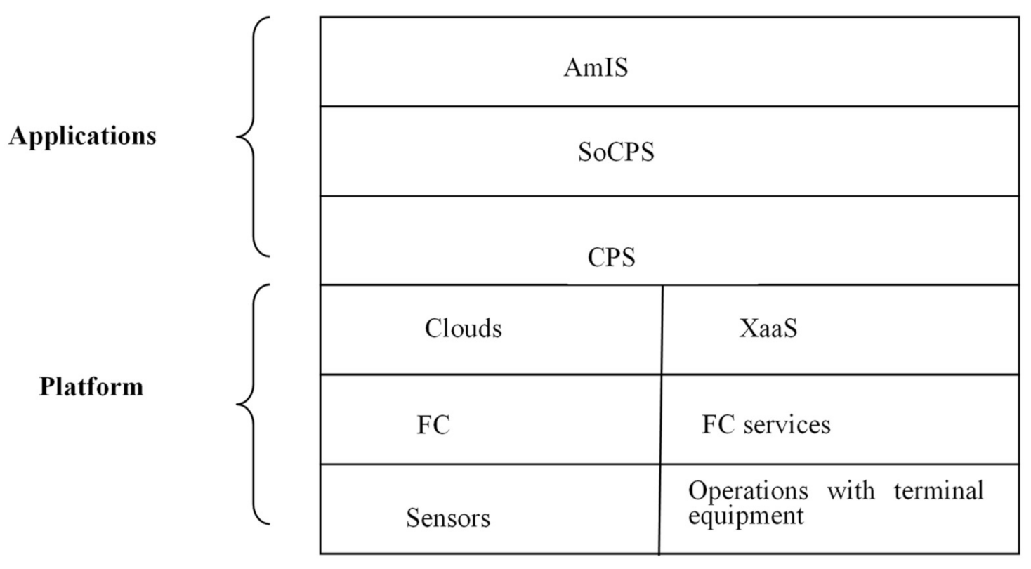
In this article, the use of the FC platform is considered as one of the possible approaches for CPS implementation. This type of CPS can be viewed as an ObS. In this case, the platform can be presented as a set of services implemented, for example, based on a framework which provides a set of standard services on three levels (
Figure 2). The top-level services are X as a Service (XaaS) models, where X is a generalization for IaaS, PaaS, SaaS and S/CaaS (storage or caching as a service) [
15].
Middle layer services correspond to fog-level services. The use of these services allows run user applications on the fog level. The list of services is defined in the standard [
8].
Low-level services provide support for working with the user’s terminal equipment (sensors, actuators).
A CPS built on the FC platform can include up to three levels: the level of separate CPS, the system of CPS (SoCPS) level, and the intelligent interface level that supports the AmIS paradigm.
The described above AmI CPS can be conceded as a reference model of ObS.
5. Suggested Approach
The suggested approach is an integration approach which uses five main paradigms and approaches: (i) data fusion approach, (ii) multi-model approach, (iii) AmI paradigm, (iv) context-aware approach, and (v) smart data paradigm.
The main paradigm is the data fusion paradigm. This paradigm has been known for a long time and is actively used. The Joint Directors of Laboratories (JDL) model is of the greatest interest from the point of view of solving the data acquisition problem [
24]. In this article, we consider a fusion model based on this model. The JDL model can be considered as a data management model for the DAS.
The second paradigm uses the multi-modal approach. The idea of using models at different stages of the life cycle of systems is not new. The similar approaches as model driven engineering, virtual reality, virtual devices, etc. are widely used. To solve problems related to the management of the structure and behavior of large distributed heterogeneous systems which consist of elements of different nature, the use of the model approach is the only real alternative.
It should be noted that the question of possibility of using the same models both at the stage of development and in run time is of great interest.
This article discusses runtime models that can be used to implement DA procedures in large and complex distributed heterogeneous systems consisting of elements of different nature, e.g., CPS.
The AmI paradigm refers to the construction of a human–machine interface and is supposed to present information to each stakeholder in its own format. At the same time, different groups of stakeholders communicate with the AmI CPS using their own domain specific language (DSL) [
25].
The context aware approach [
26,
27] is of interest for several reasons. First, obtaining contextual information can be the ultimate goal of the DAS functioning, and second, DASs operating in a CPS environment with a dynamic structure and cognitive behavior are adaptive systems, i.e., their operation requires contextual information, and third, taking into account limited bandwidth of communication channels at lower levels, subsystems operating at these levels are often built as autonomous systems and their operation also requires contextual information, fourth, the data acquisition about the functioning of the DAS itself can be treated as a process of a context building.
The idea is to use mechanisms for working with knowledge model: (i) a multi-level system of models describes the structure and behavior of the ObS, which can be the DAS itself, (ii) models are different for different levels and they can be built in terms of data, information or knowledge, (iii) the relevance of the models at all levels is maintained automatically, (iv) the relevance of the model is maintained using the data received from the ObS in the form of logs, (v) all requests from all stakeholders are made only to the models, if the required DIK cannot be received from the model then the model is rebuilt.
The novelty of the proposed approach consists, first of all, in the use of dynamic ObS models in terms of structure and behavior, which are built and maintained up-to-date automatically.
6. The Conceptual Model of the DA
The conceptual model describes a generalized DA mechanism. The proposed model is based on the well-known JDL model, which is adapted to the DAS and differs from the latter in its content. The proposed DIK fusion model (DIKFM) of DA is a system of models that describes a multi-level DA procedure and is defined as: DIKFM = <FMi, IMij>, where FMi is a set of models which describe the DA process at the i-th level, and IMij is a set of mechanisms for interaction between levels.
It is necessary to consider that the levels of the suggested model correspond to the levels of the known JDL model, but, in general, it is impossible to determine an unambiguous correspondence between these levels and the levels of the previously considered AmI CPS.
Within the DIKFM, there are five levels: (i) log processing and distribution level, (ii) object assessment, (iii) situation assessment, (iv) thread assessment, and (v) DA process estimation and refinement.
The generalized structure of the model in the form of virtual Fusion machine (F machine) is shown in
Figure 3. At the L0 level, the procedures for working with logs (querying, clearing, pre-processing logs) are implemented. At the L1 level, the information about individual objects (subsystems) is processed; the models used on the level are constructed in terms of information. At the L2 level, the information about the ObS is processed. At the L3 level, the procedure of analyzing information about the ObS status and evaluating potential ObS problems and various threads is implemented. At the L4 level, the process of managing the DA procedure is implemented.
This model resembles the well-known JDL model of data fusion, but the proposed model has several fundamental differences. The JDL model assumes the operation of a data fusion system on the principle of a pipeline, when raw data are received at the input, and the model of the situation appears at the output. Suggested F machine operates as an event driven system.
7. Multilevel Structural and Behavioral Models
Let us take a closer look at the DA process in AmI CPS. As mentioned earlier, one of the distinguishing features of modern AmI CPSs is the high level of structural and behavioral dynamic. Sometimes, obtaining information about the structure and/or BP occurring in the distributed systems is the ultimate goal of DA, sometimes it is an intermediate result. The task of determining the structure and behavior of the ObS can be correlated with L1 level (object assessment) in terms of the F machine.
DA tasks. In the most general form, the DA can be defined as the process of obtaining the required DIK based on the available DIK about the ObS and the results of executing a certain procedure (DA Procedure Results, DAPR) DIKti = f(DIKti-1, DAPR), where DIKti is a required DIK and DIKti-1 is an available DIK. In turn, the DAPR is formed based on the DA goals and the available knowledge about the ObS. DAPR = f(NDIK, DIKti), where NDIK is needed DIK. NDIK can be obtained either because of the operation of the DAPR, or because of the transformation chains of the results of DAPR execution (DAR).
The DA task can be formulated in terms of eight entity classes.
where SH is a set of observers (stakeholders), ObS is an observable system, DASS is a DA subsystem, DSLRQ, DSLRS are a set of DSL requests and a set of DSL responses, POL—a set of policies, SCR—a set of scripts, and LOGS—a set of log files or just logs. The solution of DA task in this statement assumes solving two main subtasks: (i) the formation and presentation of requests to the DA System (DAS), (ii) the presentation of results in terms of DSL. The first task involves performing the transformations DSLRQ🡪Vu and Vk🡪DSLRS, where Vu is the vector of values to be determined because of the DA procedure realization, and Vk is the vector Vu, populated with parameter values. DSLRQ and DSLRS are DSL requests and responses (note that different user groups may use different DSLs). The second problem involves the trans formation Vu 🡪Vk or Vk = f (Vu, ObSP), where ObSP are the ObS parameters. Separate parameters of the ObSP may be unknown.
DA procedure. The DA procedure can be described as a BP or as an automaton.
Description of the DA procedure in the form of a BP. The DA procedure itself can be defined as a transition from vector X to vector Y:X🡪Y, where X is the input vector and Y is the output vector. The input vector X contains an arbitrary finite number of elements, each element can be either simple or complex (include an arbitrary number of simple or complex elements). The number of nesting levels can be any, but not infinite. Each element is assigned a vector of parameters of arbitrary length.
Each element vi has at least three attributes: (i) ID, (ii) parameter value, and (iii) a reference to the source. ID is the unique element identifier; reference is the pointer to the method for getting DIK about the value of the element. Each element may have any number of parameters.
The value vi can have a certain value vi = known (1) (1) or an indefinite valuevi = unknown (0). The set of elements having the type known can be considered as a priori knowledge about the ObS. All elements of the output vector Y have the values vi = known.
The reference field specifies how to get the DIK about the element. It can be presented as
In the special case, each element X corresponds to an element Y that has similar attributes. This is the case of a static ObS structure. If the structure of the ObS is dynamic (i.e., new elements may appear in the process of functioning, and old elements may disappear), then the structure of the vectors X and Y does not coincide. Then fusion mechanisms are used. In relation to the subject of the study, the second (general) case is of interest.
The values of the parameters of the output vector Y are used to form the required representations. It may take several steps to move from the source vector to the final vector. Then we have a chain of transformations of the form X🡪T1🡪T2🡪Ti🡪Tk🡪Y🡪P, where Ti is the results of the intermediate transformations, and P is the required representation. This chain defines the order in which the required values are defined.
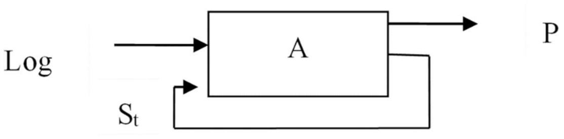
Description of the DA procedure in the form of an automaton. The automata (A) representation of the DA procedure is shown in
Figure 4. Logs are sent to the machine’s input. In this case, the machine switches from the current state St to the state St+1. The output is a representation that is formed in accordance with the user’s request: St+1 = f(St, log, P), P = f(St, RQ), where St is the current state, P is a view, RQ is the user’s request.
Basic strategies of DA. There are three basic options for organizing the DA process (DA strategies): direct DA, model based DA, and mixed strategy.
Direct DA. The procedure for direct DA can be defined as Vk = f(Vu, ObSP), where Vkis the vector of parameter values, Vu is the vector of parameters to be determined, and ObSP are the known parameters of the ObS. When a request is received, a script is generated based on the knowledge about the ObS, and the DSLRS is generated based on the results of its execution. When a new request appears, the required DIK about the ObS is searched again.
Model based strategy. This strategy, in contrast to the previous one, assumes that when a DSLRQ is received, it is addressed not to the ObS itself, but to its model. At the same time, there is a separate process that is responsible for keeping the model up to date. The procedure includes two parallel and asynchronous processes: the process of executing user requests and the process of keeping the model up to date. These processes can be represented as follows: Vk = f1(Vu, ObSM), ObSM = f2(ObSP), where ObSM is an ObS model.
The monitoring process is continuously running in the system. This process is responsible for keeping the ObS model up to date. When a request is received from a user, the ObS model is queried. Different user groups have different concerns and use different DSL.
Compared to direct DA, the model approach has two advantages: the ability to reduce response time and the ability to work with historical states. The main drawback is the need to build and store models. As the size of the system increases, it becomes impossible to have a complete model of the whole system and keep it up to date.
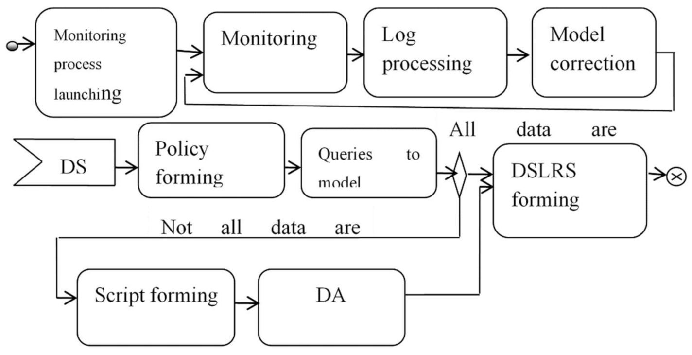
Mixed strategy. This strategy is a combination of the two strategies discussed above. The idea is that two strategies are used. If the request to the model does not give a result, the model is being completed or direct approach can be used. Using this approach allows, first of all, reduce the size of the model to an acceptable size. In general, this approach can be described as follows Vk = f0(Vm, Vd), Vm = f1(ObSM), Vd = f2(ObSP), where Vm is a vector of parameters that can be obtained from the ObS model, Vd is a vector of parameters that can be obtained by direct polling of ObS resources.
A generalized sequence of actions that implements a mixed strategy is shown in
Figure 5. When implementing a mixed strategy, three processes are involved: the process of monitoring the ObS resources, which is responsible for maintaining the relevance of the model to a certain level of detail, the process of executing a user request, and the process of collecting missing parameters values.
Description of the AmICPS in the form of a multi-level relative finite state operational automaton (MLRFSOA). It is known that the functioning of the systems that implement adaptive behavior can be described using automata models [
1,
2]. In particular, the functioning of the CPS AmI can be described using a MLRFSOA.
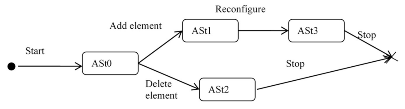
Figure 6 shows an automaton that describes the functioning of systems in terms of transitions between architectural states.
The architectural state can be described in various ways, depending on the goals of the DA. If the goal of the DA is to obtain DIK about the structure and behavior of the ObS, then the architectural state at time t ASt can be defined as ASt = <MS, MB>, where MS is the structural model, MB is the behavior model, the automaton changes its state under the influence of internal or external events. In relation to other classes of DA tasks, for example, tasks related to monitoring social networks, the concept of the ASt can be defined in a different way. In a certain sense, an ASt can be considered as some data structure that is used to accumulate the collected data.
The automaton according to
Figure 6 is a distributed MLRFSOA operating in discrete space and discrete time. Several levels are fixed and do not exceed six. The distributed MLRFSOA has a tree-like structure with links between siblings.
MLRFSOA is a class of automata in which the sets of admissible parameters are, in general, finite only at the interval of one step of behavior. It is possible to rebuild the sets of admissible input, internal and output states in the automaton, as well as the set of admissible functions of transitions and outputs of the automaton, i.e., completely rebuild the automaton.
MLRFSOA is an automaton with a variable structure, in which the functions of transitions and outputs explicitly depend on time Ai+1 = F(Ai, t) or A = (X(t), Y(t), S(t), T(t), s0), where X is a set of inputs, Y is a set of outputs, S is a set if internal states, T is a transition function and s0 is initial automaton state.
Since the automaton, A, operates in discrete time and with discrete states, it can be assumed that at each moment of time that the automaton is in some specific state si and then it can be defined as A = (X(si), Y(si), S(si), T(si), s0).
If the automaton A with a variable structure runs long enough then the number of its states in the general case for ordinary automaton becomes very large. It is known that automaton with a variable structure can generally be reduced to ordinary automata, but the number of states becomes very large, which makes it difficult to synthesize them. This can be dealt with, i.e., by generating a new automata on the fly. Thus, it seems appropriate to consider special cases when, switching to a new state, a new automata is not assigned, but only individual elements of the description are changed. In this case, an automata with a variable structure can be defined as a set of automata.
It should be noted that only in the simplest cases the structure of the considered automata is fully known, most often there is some incomplete knowledge about the structure of the automata. In this case, it is necessary to solve the problem of constructing (synthesizing) an automata. These issues are discussed in sufficient detail in the works [
28,
29,
30,
31].
Structural and behavioral model (SBM) of the ObS. For AmI CPS the ASt can be defined in terms of a structure and a BP. As a model, it is proposed to use a graph model that describes both the BP and the resources used.
The ASt is described by a multigraph that includes four attributed relationship graphs: a control flow graph, a data flow graph, a query flow graph and a resource graph.
The data flow graph (DFG) describes the relationships between data. It can also be marked up with tokens.
A control flow graph (CFG) describes only the order in which operators are executed. This graph may or may not be marked up with tokens.
The request (demand) flow graph (RQFG) describes the CPS in terms of calling procedures or accessing services. The request to execute an operator may or may not be associated with the creation of an operator. A resource graph (RSG) describes a structure in terms of subsystems and links. The considered model of ASt will be called an operating scheme (OPS).
The dynamics of the implementation of OPS can be described using the mechanism of tokens as it is done in data flow diagrams or in Petri nets.
The OPS describes the dynamics of the algorithm execution in the virtual machine that has a fixed set of resources. OPS can be considered as a functional scheme (FS) with additional restrictions on the order of execution of operators.
OPS can be defined as OPS = <O, DL, CL, RQL, RSL>, where O is a set of operators, DL is a set of data relations, CL is asset of control links, RQL is a set of query relations, and RSL is a set of resource relations.
The dynamics of the BP execution can be described in terms of defining the operator’s readiness for execution. The following conditions are used: the presence of input data, the presence of the necessary resource, the presence of a request and the presence of a control signal to run the operator.
The decision on the operator’s readiness is made in run time mode. However, some of the readiness conditions can be checked in statics at the level of input language or even at the level of the algorithm design, others in run time are considered fulfilled by default. In other words, a limited number of conditions are checked in run time.
BP management strategies. A set of special cases of building BP management systems can be described in terms of management strategies. The idea is to use a meta model, in terms of which various management models or management strategies are defined.
BP meta model. The meta model is intended primarily for describing machine-executable BPs from the point of view of the DAS.
The BP metamodel can be defined as MM = {O, R, STR}, where O are operators, R are resources, and STR are BP management strategies. In turn, the operators can be defined as O = {Ot, Om, Oc}, where Ot are data transformation operators, Om are data handling operators (storage, search, retrieval), Oc are control flow operators. Resources management can be defined as follows R = {Rp, Rtn, Re}, where Rp is the resource allocation actor (pick up), Rtn is the resource tuning actor (tuning), Reis the resource engage actor. In addition, other types of resource actors can be used.
Strategies can be defined as a high-level description of the BP management methods in terms of the guard conditions for launching operators STR = {GRi}, where guard condition GRi is the i-th variant (guard condition, trigger function, trigger) of defining the conditions for launching operators. In the most general form, the conditions for starting a certain operator within a certain strategy can be defined as GR = GRctr^ GRdat^ GRres^ Greq, where GRctr is a signal that prescribes the start of the execution of the operator, GRdat is data availability, GRres is the availability of resources, and GRreq is the presence of a request for the execution of the operator (
Figure 7).
The vector Vgr = {GFctr, GFdat, GFres, GFreq},where GF is the use of separate mechanisms for determining the readiness of actors (operators), which can take the value 0 (the condition is not checked at run time) or 1 (the condition is checked at run time) can be defined. Obviously, all the conditions must be checked. This can be done in different ways: statically (at the compilation time) or in run time, in centralized or distributed manner. Thus, it is possible to define 16 different strategies of BP managing (
Table 1).
Special case BP management models. The strategies presented in
Table 1 can be divided into pure and mixed strategies.
Pure strategies. In the scope of the developed approach, four pure strategies are distinguished.
Directive (control flow) strategy. This strategy assumes that all actors are defined before the BP starts execution and are launched by only one control signal. Data presence is controlled in run time mode. Resources are also assigned in statics and at the execution stage it is assumed that all the necessary resources are defined and free. Concurrency is described by the branch and merges operators. This strategy option can be considered as a pure control flow.
Data flow strategy. This strategy assumes that we have only data flow graph. Resources are assigned at run time, and directive management is not used. This option can be considered as a pure data flow [
32].
Resource or R-strategy. This strategy assumes that all actors are ready for execution start and the only need to assign resources to execute them. In this case, the strategy is defined as a set of business rules. This strategy is used when actors are not linked in any way. For example, this situation takes place when the OS assigns independent processes to run.
Demand driven or request strategy (Z strategy). This strategy, also known as demand-driven computing, assumes that all actors are ready for execution, and the order of their execution is determined by the need for the results of actors’ execution. It is also known as a demand driven computations. The two options can be selected: (1) all actors are created and the rules only determine the order of their launching; (2) actors can be created during the execution of the BP. Recursive machines worked on this principle, and a similar principle is used in functional programming languages, as well as in systems that work on the Map Reduce principle [
33].
Mixed strategies. Pure strategies are used in practice rarely. More often some combination of strategies is used.
Demand driven-resource strategy. The strategy is used as the main strategy. Computations start by calling some root program, which can call nested programs. The number of available resources is limited. This strategy is used, for example, when implementing a Lisp program on a single-processor system.
Data flow-demand driven strategy. This strategy assumes that the process is executed in two passes. On the first pass, a calculation tree is built using the query engine, and when the tree is built, the program is executed in data flow mode. At the same time, it is considered that the number of resources is unlimited. This situation occurs when using virtual resources.
Data flow-resource strategy. This strategy is like the data flow-demand driven strategy. The difference is that resources are limited, for example, multiple statements can be assigned to execute on a single processor.
Directive-demand driven strategy. A directive-demand driven strategy can be defined as a strategy that combines directive and query management. An example is traditional procedural programming. At the same time, it is considered that the number of resources is not limited. This situation occurs when using virtual resources.
Directive-demand driven-resource strategy. This strategy is like the directive-demand driven strategy, but the number of available resources is limited.
Directive-data flow strategy. This strategy uses both data flow and directive management mechanisms. This strategy was used in data flows machine and was implemented in the form of acknowledgments [
32].
Directive-data flow-resource strategy. This strategy is a combination of data flow and directive strategies in conditions of limited resources. This strategy may be interesting when the BP is organized on two levels. At the top level (at the level of large modules), the query strategy is implemented, and at the bottom—the data flow strategy is realized.
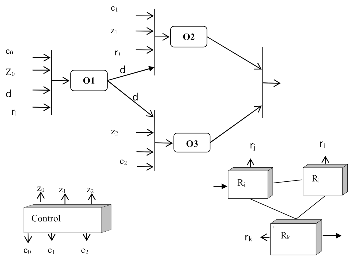
A generalized model for presenting information about ObS is shown in
Figure 7. The model is based on data flow graph that defines data dependencies. At the same time, as conditions for the readiness of the operator O for execution, in addition to the availability of data, the presence of a request Z for its execution, a signal C that prescribes the execution of the operator O and the readiness of the resource R for the execution of the operator are required. The availability of data D is determined by the arrival of data from other operators. The Z requests and C signals instructing the operator to start executing are generated by the control unit.
The available resources are described by a separate graph. Information r about the state of resources is also received at the inputs of operators O. It should be noted that the considered model describes the functioning of the ObS only at one level. In relation to the class of systems under consideration, it is necessary to describe the ObS at several levels. Different models can be used at different levels.
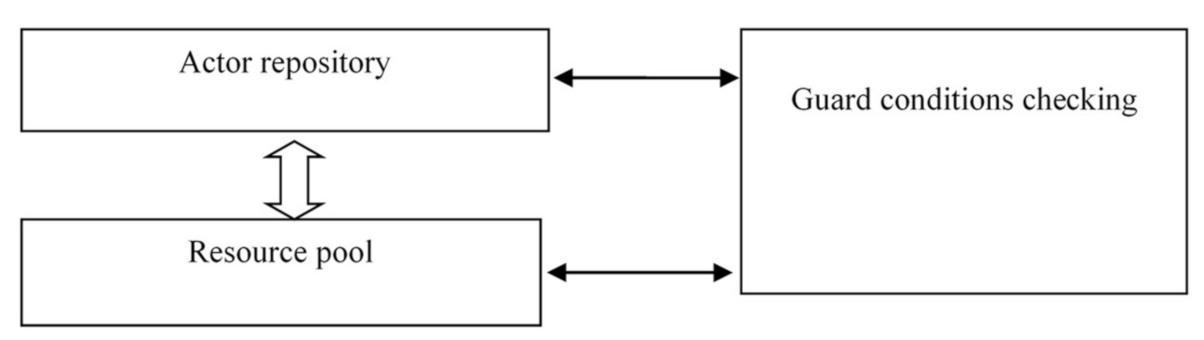
A virtual machine for implementing management strategies. BP management strategies can be described in terms of a virtual machine which implements BP management strategies. The structure of such machine is shown in
Figure 8.
The machine includes three subsystems: an actor repository, a resource pool, and an actor readiness checking subsystem.
The actor repository stores an arbitrary number of actors (operators). Each actor can be either an actor or a container that stores an arbitrary number of actors. The depth of nesting is unlimited. All actors belong to the same BP and the links between actors are part of the description of the actors themselves. The resource pool defines the set of available resources. A state vector (free or busy) is assigned for each resource. The actor readiness subsystem determines the order of actors are started. The execution of the BP is considered as the process of firing actors in accordance with certain rules. The rules are determined by the strategy used.
Approaches to implementation and tasks to be solved. It should be noted that the use of the proposed meta-model can be considered as a generalization of the models used in the field of process mining [
34]. At the same time, the use of the proposed approach allows build more complex models that can be useful for solving problems of monitoring and managing complex technical systems with a dynamic structure and behavior such as: (i) implementation of BP restructuring algorithms, (ii) optimization of resource usage, (iii) monitoring of BP, and (iv) tracking of services requests.
The task of restructuring may arise for several reasons. The structure of the hardware and software platform where the observed BP runs can be changed (contextual restructuring). The BP can be restructured for adaptation to incoming data (content restructuring) or changes of the context. It seems appropriate to use strategies based on the reconstruction of the data flow graph with the subsequent superimposition of the resource graph for solving this problem. A business rule system can be used for this purpose.
BPs that use query management strategies. Query strategies are increasingly used in real distributed systems. The use of these strategies is closely related to use of functional programming languages. It is obvious that the considered BP management mechanisms are quite general and defined by metamodels. Based on these metamodels, private models depending on the purposes of data collection are built.
The necessary data for building the required models can be obtained from two sources: logs and DIK contained in the current model. New information comes in the form of logs, which are formed either as the results of the scripts execution or as information about events in the ObS.
8. Automatic Generation of the ObS Model
Obviously, for systems with a dynamic structure and behavior manual construction of their models does not make sense. This is expensive, it is associated with very large delays and expert errors are not excluded. A human who performs the functions of an expert can be involved on demand. For automatic building and/or keeping the ObS model up to date it is necessary to solve two main problems: (i) building a multi-level ObS structure model based on incoming logs, (ii) building a BP model in C, D, Z, R terms.
Typical tasks of BP building. It is difficult to imagine a situation when there is no knowledge of both the ObS structure and behavior. As a rule, the target model is built based on existing model and contextual knowledge:
Mt←<Mc, LOGS, CDIK>, where Mt is a target model, Mc, is a known (current) model, LOGS are the logs from ObS, and CDIK is a contextual knowledge.
Special cases of DA task statements. Depending on available knowledge and goals of DA, four basic variants of DA task statement can be defined (
Table 2).
Task A. Checking the model relevance. It corresponds to the case when both the static model (the ObS structure) and the dynamic model are known, i.e., the models related to all the ObS structural levels that are of interest are known. In general, Task A can be formulated as follows. Using the well-known static and dynamic models of the ObS and logs, check the relevance of the models and build up-to-date static and dynamic models with a given quality indicators if the models are not up to date.
Task B. Building a behavior model based on the structural model and logs. In this case, the structure of the ObS is known, but there is no knowledge about the BP occurring in the ObS. This task can include the classic process mining problem [
34] of restoring the structure of the BP either from scratch or according to a known BP dynamic model of a higher-level.
Task C. Building a structural model based on the behavior model and logs. The BPs that are running in the ObS are known or can be recovered from the logs. It is necessary to determine the real structure of the ObS.
Task D. Construction of structural and behavioral models by the descent method. There is no complete information about both the ObS structure and the BP. There is only a set of logs. It is assumed that the structure and semantics of the logs are known. This task can be solved with the step-by-step procedure when using available knowledge, i.e., about the ObS structure on i-th level and log information we build the BP model for i-th level etc.
A more detailed analysis of the tasks can be found in [
34] where reduction of the tasks to two tasks that are the task of synthesizing multi-level BP model from logs and the task of synthesizing multi-level structures from logs is shown.
The problem of automatic BP models building has been known for a long time. In the scope of the process mining approach, solutions of this problem are proposed in different statement sin [
34]. Building models of multi-level processes in terms of data flows and query flows does not cause big problems in general.
The solution of the multi-level models of dynamic structures building problem can be found in the publications of the authors [
28,
29,
30,
31]. Thus, we can assume that the algorithms for solving problems of automatic construction and maintenance of ObS structural and behavioral models are known.
9. Implementation of the DA Procedure Using Policies and Contexts
As mentioned earlier, according to suggested approach the two key procedures related to DA can be defined: the procedure for constructing an up to date ObS model and executing DA script. The procedure for constructing the model was discussed earlier in
Section 8. The DA procedure is discussed below. The DA procedure is implemented via a script. Since the ObS has a dynamic structure and behavior, the model is changing all the time. This makes it impossible to build a script in statics, i.e., the script must be built in dynamics according to the REQUEST--> SCRIPT--> RESULT scheme.
The script can be compiled or executed by an interpreter. The script generation task can be defined as SCRIPT = F (REQUEST, MODEL). In fact, this is the task of automatic program building. It should be noted that the problem of program synthesis is not new, it is solved in different statements when building Prolog machines [
2]. In addition, an approach to network management using the policy mechanism is of significant interest [
35,
36,
37]. The approach to automatic script construction developed in this paper is based on the ideas listed above.
The use of policy mechanism has a certain difference from the classical approach used in relation to network management. The difference is that in the case of using policies in the DA, policies are used as a mechanism for managing the DA process. The overall transformation chain is as follows: DSL_REQUEST--> Policy--> Script--> DSL_RESPONSE.
Usage of the policy engine allows manage the DA process using a system of rules. The rules can be formulated in business terms, i.e., in DSL. The system of rules forms a hierarchy. Movement in the hierarchy is carried out from top to bottom.
In the scope of the proposed approach, the key concept is the concept of policy, which is defined as “a policy is a set of rules that are used to manage and control changes and/or maintain the state of one or more managed objects,” according to [
37].
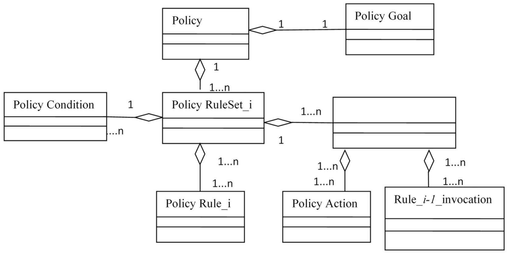
More formally, a policy can be defined as POL = < GOAL, RULESET>, where GOAL is the goal of DA and RULESET is an ordered set of rules for achieving the goal. Obviously, the policy can be represented in the form of an object (
Figure 9). The specifics of applying the policy mechanism in relation to the DAS are as follows: (i) the input of the policy processor, which realizes policies, receives requests that are initially formulated in terms of one of the DSLs used, i.e., the dictionary in which the requests are formed can be significantly limited, (ii) different user groups use different DSLs, (iii) different dictionaries are used at each level of the AmIS CPS stack.
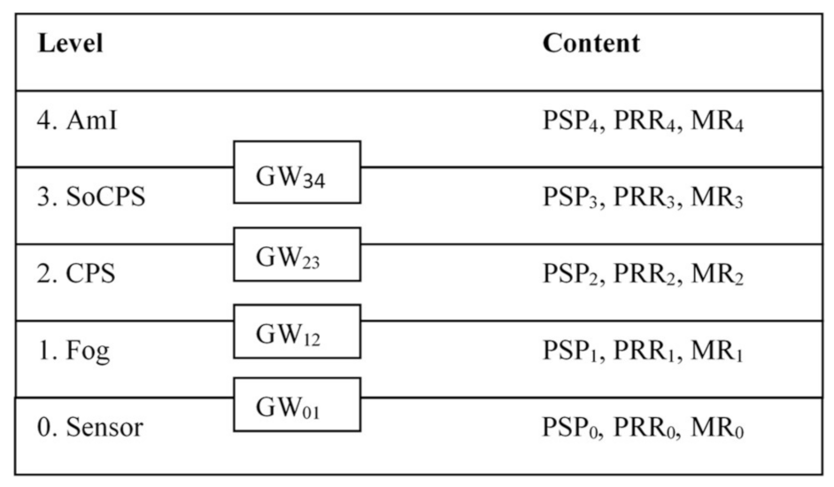
The Policy and Script Processor (PSP). PSP is a distributed processor. At each ObS structural level, in addition to the PSP, there is a repository of policies and rules (Policy and Rule Repository, PRR), repository of models (Model Repository, MR) and gateways (GW) (
Figure 10).
A generalized algorithm for the functioning of the PSP. A policy is defined as a goal and a way to achieve it. Policy is a multi-level concept. Each level implements its own set of policies.
A i-th structural level policy can be defined as <POLij>:: = <GOALi+1> <{SubGOALi}> <Fusion Procedure i>, where POLij-j-th policy, GOALi+1 is a higher level goal, SubGOALi is the list of subgoals of the Level i, Fusion Procedure i is the reference to the DIK fusion procedure of the i-th level.
In the most general form, the idea of working with policies is as follows. It is assumed that the PSP has a five-level tree structure. The top-level PSP (PSP 4) receives a request from the user as a DSL request and transforms it into a policy DSLRQ--> {POL}. DSLRQ is a DSL request. For example, it can be a request from a service engineer about the status of a device, or a request from an operator about a situation.
For each goal, the policy is defined. The policy selection is made considering the context (CTX). Therefore, POL = F(GOAL, CXT). (Usage of the context will be discussed below).
In addition to the goal, the policy includes a list of sub-goals and a pointer to the fusion procedure. A sub-goal is a DIK identifier that refers to the underlying level. For each of the sub-goals, the PSP runs the corresponding policy at the underlying level, accessing it though the gateway. When all the required DIKs at the i-th level for the j-th request are collected, the fusion procedure is started, which outputs a pointer to the resulting object that contains results of fusion.
The step-by-step algorithm of PSP functioning for Levels 2–4 looks like the following:
Step 1. Define a policy based on the goal and contextual information
Step 2. If you can collect data at the current level by getting it from the model, then realize DA procedure
Step 3. For each of the sub-goals, run the policy at the underlying level
Step 4. Wait for all the DIK arrival
Step 5. If all DIK are received, then run the fusion procedure.
Step 6. Move the result to the top level.
The difference is that the list of goals is determined from the DSL request and the result is transformed into a DSL response for the top level. Further, if you cannot get the required data, an error message is returned at the lower level.
The process described above corresponds to the PSP operating as an interpreter. A script can be compiled and saved as an executable file. In this case it is possible to use script many times, but before usage, it is necessary to check the model for relevance. In this case, the typical query strategy is realized. Nowadays there is a rich experience in building various types of systems that implement this strategy [
2,
33].
Using contexts when building an AmI CPS DAS. The concept of context is actively used in various subject areas like linguistics, translation theory, system software, in the study of formal languages and grammars, as well as in the development of decision support systems. However, in different subject domains this term has different meaning.
As applied to the DA domain, the concept of context and context processing is closely related to the concept of pervasive computing. From this point of view, this concept is defined as “context is any information that can be used to characterize the situation of the subject” [
27].
Contexts can include information like location (for example, people or objects), time, application execution status, computing resources, network bandwidth, activity, user intentions, user emotions, environmental conditions [
26], etc. Thus, the concept of context turns out to be related to the concept of situation, which is defined as “a description of the states of the relevant subjects”. Other definitions of the concepts of context and situation can be found in [
26,
27].
Therefore, using contexts, it can be assumed that each statement is true if the conditions defined in the context are fulfilled: P = F(CTX, p), where p is the original statement, CTX is the context.
From the acquisition of DIK point of view, the context should be understood as the area where the specified DIK were acquired and within which it should be considered as trusted. Thus, the context can be defined as a system of constraints.
It is possible to use another interpretation of the term context, when different DIK elements have different importance or weights in different contexts. In this case the context defines the DA procedure minimizing the volume of analyzed information coming from various devices.
Classification of contexts. The concept of context has many aspects. Contexts can be used for a variety of purposes like supporting pervasive computing mechanisms, meta-rules, a repository of shared DIK, a way to accumulate DIK about the environment, or a DIK caching method.
In terms of behavior, contexts can be divided into passive and active contexts. The passive context is a simple DIK storage, but the active context can initiate some actions.
From the point of view of the described by the context subject, internal contexts which describe the DAS itself and the external context can be distinguished.
From the time point of view (time aspect) contexts can be classified as the current context, which are relevant at the given moment of time, the historical, which relates to a certain moment of time in the past, the static (not changed during the time of the problem solving), the dynamic (which can change while solving the problem), the temporary or auxiliary (TMP), which is created for the convenience of processing.
A variety of approaches can be used to implement the context like flat databases (key-value), object-oriented (OO) models, and graphs it can be knowledge graphs, ontologies, different XML schemas, analytical models that are defined using various logics.
Contexts can be formed both manually and automatically.
From the user’s point of view, contexts can be divided into physical contexts (user location and time), environmental contexts (weather, light, and noise level), user contexts (health status, mood, planned activities), social contexts (group activity, presence of group members), etc.
Context-aware policies. The term “context-aware policies” (CAP) can be defined as policies which implementation can be influenced by the context. Three main types of CAP can be defined. The first type of CAP assumes the influence of the context on the policy choice POL = <GOAL, RULESET, CTX>. The second type of CAP assumes the influence of the context on the set of rules that implement the policies POL = <GOAL, RULESET>, RULESET = F(RULESETi-1, CTX). CAP of the third type assumes the influence of the context on the rules themselves that implement the policies POL = <GOAL, RULESET>, RULESET = <r0,...ri, ... rn>, where ri is the i-th rule. It is obviously possible to combine these approaches.
In the first case, one simply selects a policy from the list of available policies. The list of policies and the policies them self-remain unchanged. The context processor implements two parallel and asynchronous processes: the process of keeping the context up to date and the process of selecting the current policy. The process of keeping the context up to date can be described as CTXt = F(CONTEXTt-1, Event), event—a context-relevant event. The process of selecting the current policy can be defined as POL = sim (CONTENT, {Policy Condition}), where {Policy Condition} are attributes of POL objects stored in the policy repository. The operation of finding the nearest similarity sim is quite well known [
38].
The second approach is more flexible. Policies are formed from a set of ready-made rules using met rules. Meta rules are rules for defining policies. This approach corresponds to the case when the script and the policy processor uses compiled files. In this case, the scripts are saved and then executed. This mode can be useful when, for example, it is necessary to track history.
The third approach assumes the automatic construction of rules based on the collected data, context DIK and metrics of the DA process. This approach makes it possible to overcome the main drawback of rule-based systems, when rules based on the knowledge of a human expert are used, but the expert may be wrong, and his knowledge may be uncertain or received in different context. In this case, data mining algorithms as a means of optimizing the DA process can be used. The proposed algorithm is the following:
Step 1. Manually define the original set of policies
Step 2. Accumulate statistics on the effectiveness of DA
Step 3. Start the rule generation procedure
Step 4. Using the data mining algorithms find the required rules
Step 5. Compare the used and received rules
Step 6. Correct the rules
Step 7. Go to step 4.
Nowadays, the problem of finding the rules can be considered as solved. Detailed descriptions of the algorithms of rules mining are described, e.g., in [
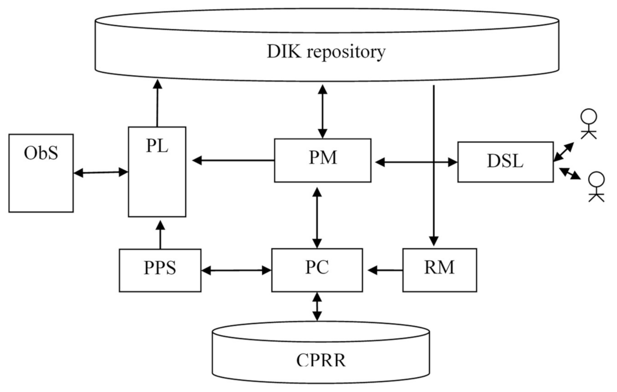
39]. However, to use them, you need data sets that can be obtained from a ready-made DAS. Therefore, it seems that the solution is to use expert knowledge as a zero iteration with the possibility of correction. The correction can be performed at any of two levels of contextual processing: at the policy level and at the level of individual rules. The generalized structure of a virtual machine that uses context-sensitive policy mechanisms is shown in
Figure 11.
The virtual machine in
Figure 11 includes the following main elements: the DIK repository, the Context, Policy, and Rule Repository (CPRR), the Observable System (ObS), the Log Processor (PL), the Model Processor (PM), the Policy and Script Processor (PPS), the Context Processor (PC), the Rule Mining Processor (RM), and the DSL Processor (DSL). The RM module scans the collected data sets and data describing the DA process and generates rules that are used for the policies formation.
For different levels of FC platform different approaches for working with context can be used.
The semantics of operations on contexts are essentially determined by the way the context is represented. It is possible to define the following core operations for context processing:
1. Creating the context (context element), CrC;
2. Deleting the context (context element), DelC;
3. Changing the context element, ChC;
4. Compare contexts, SIM;
5. Set the value of the context element, SetE;
6. Read the value of the context element, GetE;
7. Subcontext selection, SelSubC;
8. Merge contexts, MergeC;
9. Context import, ImportC;
10. Context export, ExportC.
As mentioned earlier, different mechanisms can be used to represent contexts, such as flat databases (key-value, K-V), object-oriented (OO) representations, graphs. One can use knowledge graphs, ontologies, XML, analytical representations that are defined using various logics. In the
Table 3. The typical ways of representing contexts for different structural levels of FC platform are given.
10. Architectural Solutions of DAS
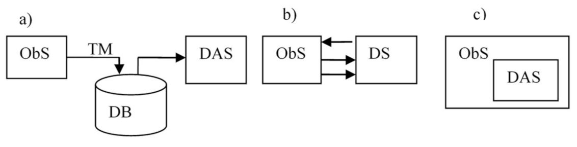
The architectural solutions of DASs are focused on DAS in AmI CPS, they are essentially determined by the way of interaction of DAS and ObS. As mentioned earlier, AmI CPS are mostly distributed systems, and at the lower levels (sensor and fog), they can be considered as loosely coupled systems due to limitations on the bandwidth of communication channels. There are three basic variants of realizing interfaces between the ObS and the DAS: (i) remote monitoring, (ii) standalone DAS, (iii) build in DAS. These options are shown in
Figure 12. In a remote monitoring DAS, the ObS and the DAS are connected by a telemetric channel. In this case, postmortem processing is most often implemented (
Figure 12a). In the second case (standalone DAS) ObS and DAS are connected by numerous communication channels (
Figure 12b). In this case, the communication channels with the ObS usually have limited bandwidth. In the third case (
Figure 12c), the DAS elements are built into the ObS subsystems (build in DAS). In addition, there may be many intermediate variants.
If the remote monitoring mechanism is implemented, then usually a part of the DAS can be placed inside the ObS. In this case, a compromise between increasing the volume of data transmitted through telemetry channels and the cost of additional equipment for pre-processing collected data is to be found. In the second case, the DAS is realized as standalone system, and DAS can be built on the principle of edge computing. In the third case, the structure of the DAS is completely determined by the structure of the ObS, the nodes of which are the objects of observation.
If the DAS is implemented as the stand-alone system, then it can be a physical system. When DAS is realized as a build-in system, then most often virtual machine solutions are used.
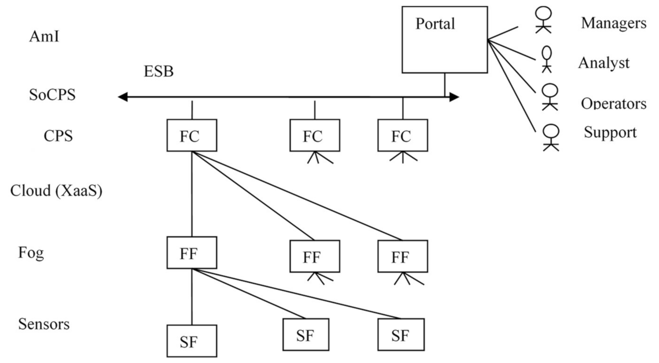
A typical variant of the distributed DAS deployment for AmI CPS is shown in
Figure 13. Each level as a rule uses its own F machine. For the sensor and the fog levels the Sensor F machine (SF) and the Fog F machine (FF) are used. At the Cloud level XaaS services are deployed, which are used by all levels except the sensor level. SoCPS level is an integration layer that can be implemented, for example, with the help of Enterprise Service Bus (ESB). The AmI level can be implemented in the form of a portal, which realizes the pervasive computing mechanisms.
Depending on the specifics of the problem statement and the subject domain, different architectural solutions can be used to implement context aware DAS, a complete description of which can be found, e.g., in [
17,
40,
41]. When building a DAS, such architectural styles as service (micro service) architectures, multi-agent systems, and systems built on the blackboard principle can be used.
One can define three main approaches to the realization of the model according to
Figure 7: the implementation of the model in JAVA in the form of an object model, ontologies [
42] and knowledge graphs based solutions [
43,
44]. JAVA based solutions allows receive minimal delays, but this approach is rather complex from the point of view of programming. The use of ontologies and knowledge graphs (KG) provides slower solutions, but allows use of existing tools, such as SPARQL [
45]. An agent-Based approach also can be used [
46].
Since the models are quite complex, it is advisable to implement them as cloud services.
11. Use-Case
The main goal of this example is to illustrate: (i) how suggested approach can be tailored to concrete problem solving; (ii) how ontologies and knowledge graphs can be used for models implementation. In the use-case, a cable TV operator telecommunication network that provides services, applications, and sells access to content is considered. The task is to check the states of set top boxes (STB) which are functioning in a telecommunication network (TN).
Specialists of customer support service define a set of policies for checking STB states or their elements. The values of the parameters are split into Green (normal functioning of STB/STB element), Yellow (borderline functioning of STB/STB element) and Red (failure of STB/STB element) zones.
The policies are defined for two situations (contexts): (i) all the parameters that should be considered according to the policy are in the green zone; (ii) any parameter is in a yellow or red zone.
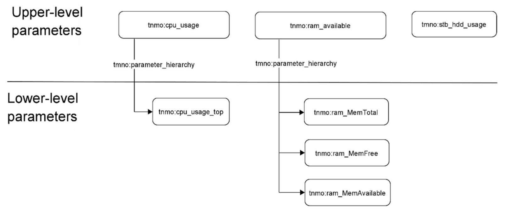
The analyzed STB parameters are split into upper level parameters and lower level parameters (
Figure 14).
Policies are defined as:
If all the upper-level parameters are in green zone—the further parameters gathering is not required.
If one of the upper-level parameter is in yellow or red zone, the corresponding lower-level parameters must be collected.
The sequence diagram of checking the state of an STB using polices is shown in
Figure 15.
The sequence diagram details are:
Step 1. The operator creates the request about user device state to TN monitoring system.
Step 2. According to policy rules, the set of requests for device upper-level parameters values is built, than these requests are sent to the device directly or via a TN monitoring system.
Step 3. The monitored device sends the parameters values to the TN monitoring system.
Step 4. The TN monitoring system writes the received parameters to knowledge graph and notifies the policy processor that implements policy control functions about the device data update.
Step 5. Policy processor analyzes the results and if all the upper-level parameters are in the green zone, results are sent to the operator with no further data processing. If not—execute Step 6.
Step 6. According to policy rules, the requests for the values of device lower-level parameters are built. Than these requests are sent to the device directly or via a TN monitoring system.
Step 7. The monitored device sends the parameters values to the TN monitoring system.
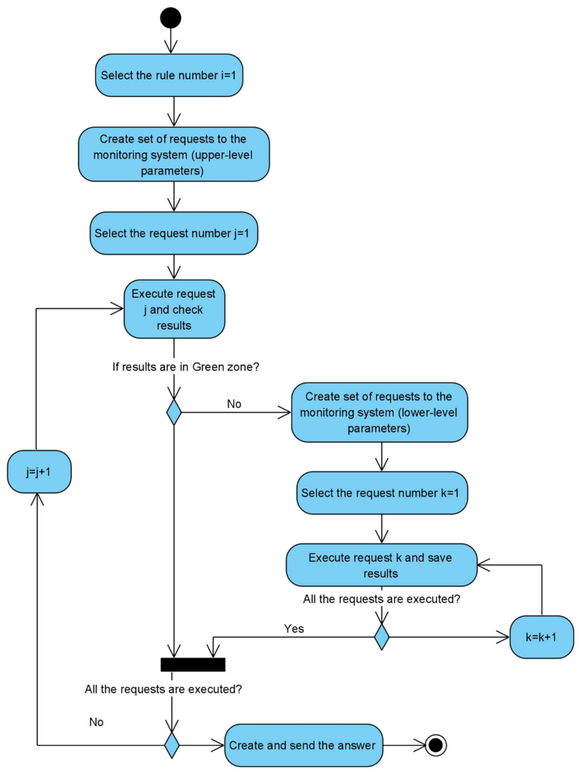
The activity diagram of checking the state of an STB using polices is presented in
Figure 16. The workflow consists of the following steps:
Get upper-level parameters from STB.
If all the parameters are in the green zone—return answer with green STB state.
If any parameter is in yellow or red zone—request daughter parameters from lower level then return details about the yellow or red state.
Step #3 can be repeated according to parameters hierarchy structure.
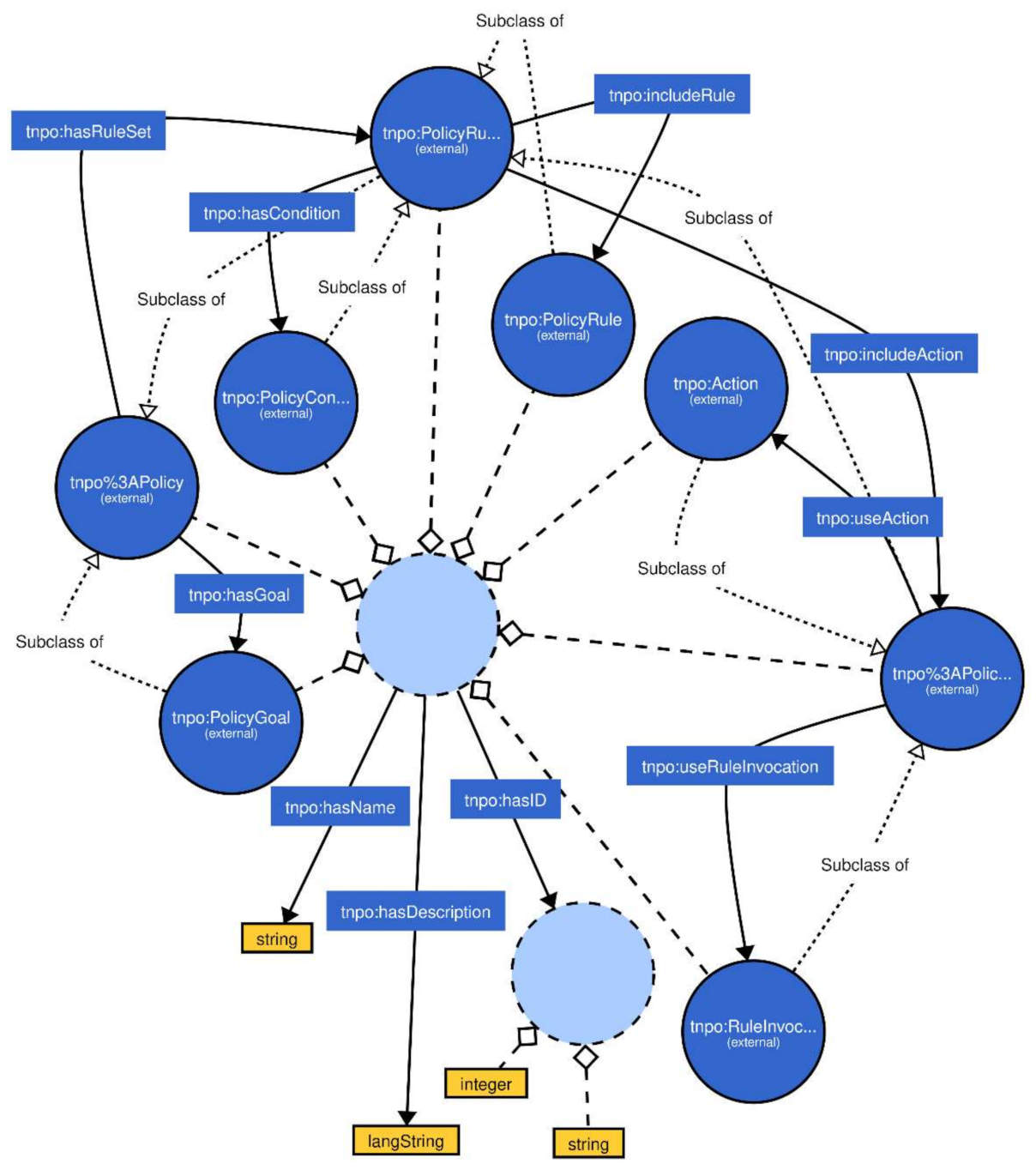
For checking the states of STBs using TN monitoring system based on knowledge graph, the knowledge graph ontology has been created (
Figure 17).
The suggested ontology contains the policy entity-relation model. This model includes the following:
Classes:
Policy;
Action;
Policy Action;
Policy Condition;
Policy Goal;
Policy Rule;
Policy Rule Set;
Rule Invocation;
Object Properties:
Has Condition;
Has Goal;
Has Rule Set;
Include Action;
Include Rule;
Use Action;
Use Rule Invocation
Data Properties:
Has Description;
Has ID;
Has Name.
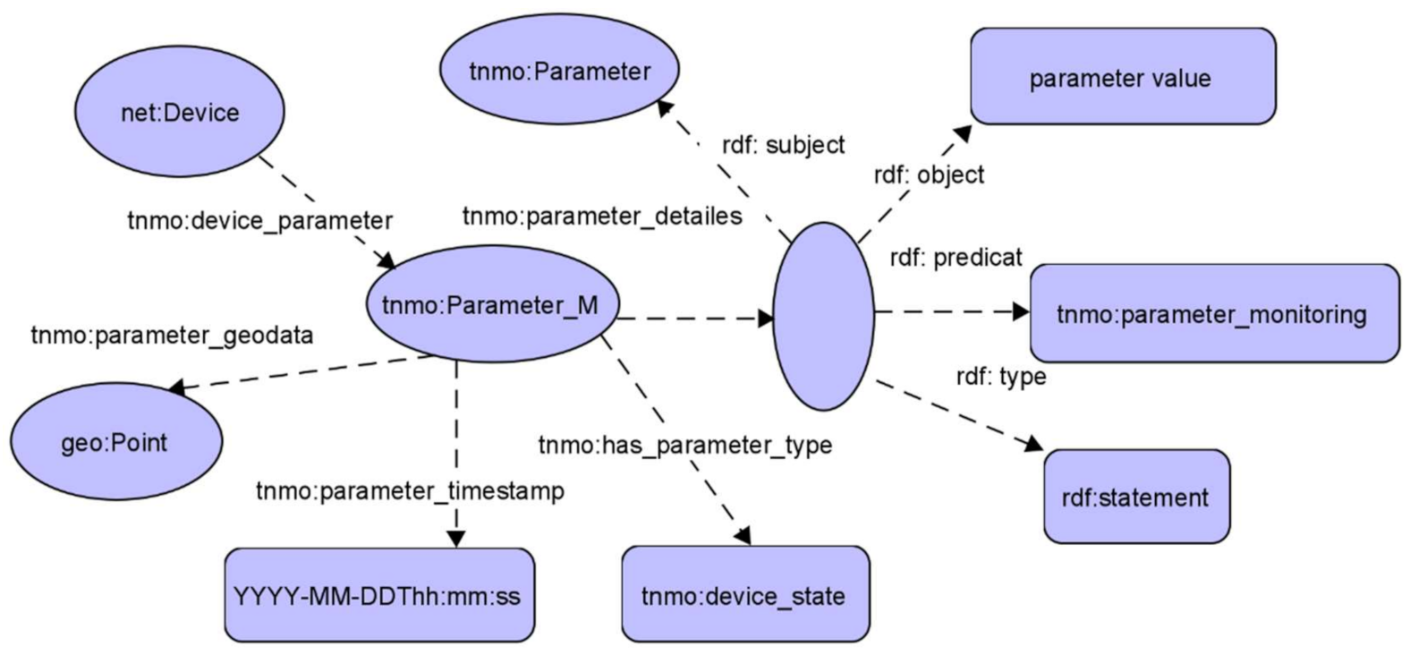
Based on the suggested policy ontology, the following KG for the TN monitoring system was built (
Figure 18).
The suggested KG structure contains the following elements:
SPARQL requests/responses to the knowledge graph are presented below.
The rows of the response are shown in
Table 4.
The rows of the response are shown in
Table 5.
To provide an analysis of time completion of checking the STB states the following models of the networks were considered:
Network #1: Number of monitoring object = 100; number of parameters measurements = 700.
Network #2: Number of monitoring object = 1000; number of parameters measurements = 7000.
Network #3: Number of monitoring object = 10,000; number of parameters measurements = 70,000.
Network #4: Number of monitoring object = 10,0000; number of parameters measurements = 700,000.
To get data about the STBs states from the knowledge graph the SPARQL requests considered above were used.
For each network the average execution time and the percentage of the detected failures were calculated. The results in interval of 24 h are presented in the
Table 6.
The number of detected failures is less then 100% due to some failures cannot be detected if a TN device was not accessible for monitoring for some time or if monitored TN device parameters do not provide assured failure detection. The probability of the such situations can be estimated in interval of 0.001–0.01 and depends on TN size.
The use of the proposed approach made it possible to significantly reduce the staff of service personnel. Working in automatic mode, it makes possible to detect more than 98% of errors and reduce the broadcast recovery time from several hours to several minutes.
12. Conclusions
The problem of DA in large-scale distributed CPS with a high level of variability of structure and behavior is important for practice, but it is quite difficult to solve the problem. The article offers a model approach to solving this problem. The proposed approach is based on the following ideas: (i) the collected data is presented as a set of automata models which describe the structure and behavior of ObS; (ii) all models are built and maintained up-to-date automatically in run time mode; (iii) models are considered as separate entities, the specific type of model is determined by the requirements for the concrete DA task.
The approach considered in the paper opens prospects for solving two important tasks: (i) reaching a new level of complexity of the created systems; (ii) expanding the scope of their application by reducing the total cost of ownership by excluding a human from the process of keeping the model up to date.
The functioning of DAS is based on the joint use of algorithms for the structural synthesis of ObS objects and process mining algorithms. With this problem statement, the key requirement for the model is its synthesizability (the ability to build it in run time) and the ability to use it to fulfill requests from different categories of stakeholders.
At present, the proposed approach is ready for practical usage: MLRFSOA synthesis algorithms, as well as script synthesis algorithms are developed.
The experience of practical application of the proposed approach has shown that at minimal cost, this approach can be used to solve practical problems in telecommunication domain, it can be also successfully applied in many other subject domains, where AmI CPS are used. Further research on this topic should be carried out in the direction of expanding the scope of the developed multi-model approach. Within the framework of the developed approach, the idea of using the ObS model is laid down both as a model based on which a script is formed that implements the DA procedure and as a repository of the collected data. If we replace the model, we can easily move to other subject domains, e.g., socio-cyber-systems. In particular, the work of the authors [
47] shows the possibility of using this approach in industrial systems built based on IIOT [
48].


