Software Requirement Specification Based on a Gray Box for Embedded Systems: A Case Study of a Mobile Phone Camera Sensor Controller


Graduate School of Management of Technology, Sogang University, Seoul 04107, Korea
Computers 2019, 8(1), 20; https://0-doi-org.brum.beds.ac.uk/10.3390/computers8010020
Submission received: 24 January 2019
/
Revised: 15 February 2019
/
Accepted: 17 February 2019
/
Published: 2 March 2019
Abstract
:One of the most widely used models for specifying functional requirements is a use case model. The viewpoint of the use case model that views a system as a black box focuses on descriptions of external interactions between the system and related environments. However, for embedded systems that do not disclose most implementation logics outside the system, black box-based use case models may experience the drawback that considerable information that must be defined for system developments is omitted. To solve this shortcoming, several studies have been proposed on the use of kind of white box technique in which the dynamic behaviors of embedded systems are defined first using a state diagram and the results are reflected in the requirement specifications. However, white box-based modeling has not been widely adopted by developers due to tasks that require a lot of time in the requirement analysis phase in the initial phase of the software development life cycle. This study proposes a gray box-based requirement specification method as a trade-off between two contradictory elements (the amount of information required to develop an embedded system and the cost of the effort required during the requirement analysis phase) in terms of the two approaches, the black and the white box-based models. The proposed method suggests that an appropriate depth level of embedded system modeling is required to define the requirements. This study also proposes a mechanism that automatically generates an application programming interface for each component based on the created model. The proposed method was applied to the development of a camera sensor controller in a mobile phone, and the case results proved the feasibility of the method through discussion of the application results.
1. Introduction
Embedded software refers to software that controls specific functions embedded in electronic products, from small appliances, such as mobile phones, digital cameras, and MP3 players, to digital control systems, such as vehicles and airplanes [1]. For the requirement specifications of embedded software, most embedded system development organizations have used a scenario-based specification method from a black box perspective; this method has been widely employed in existing business applications. One of the most widely used scenario-based methods for specifying the functionality of a system is a use case model [2,3], which focuses on descriptions of interactions occurring between the system and the user. However, most implementation logics in embedded systems start with interactions either with hardware inside the system or with other external software products rather than with interactions between the system and external users.
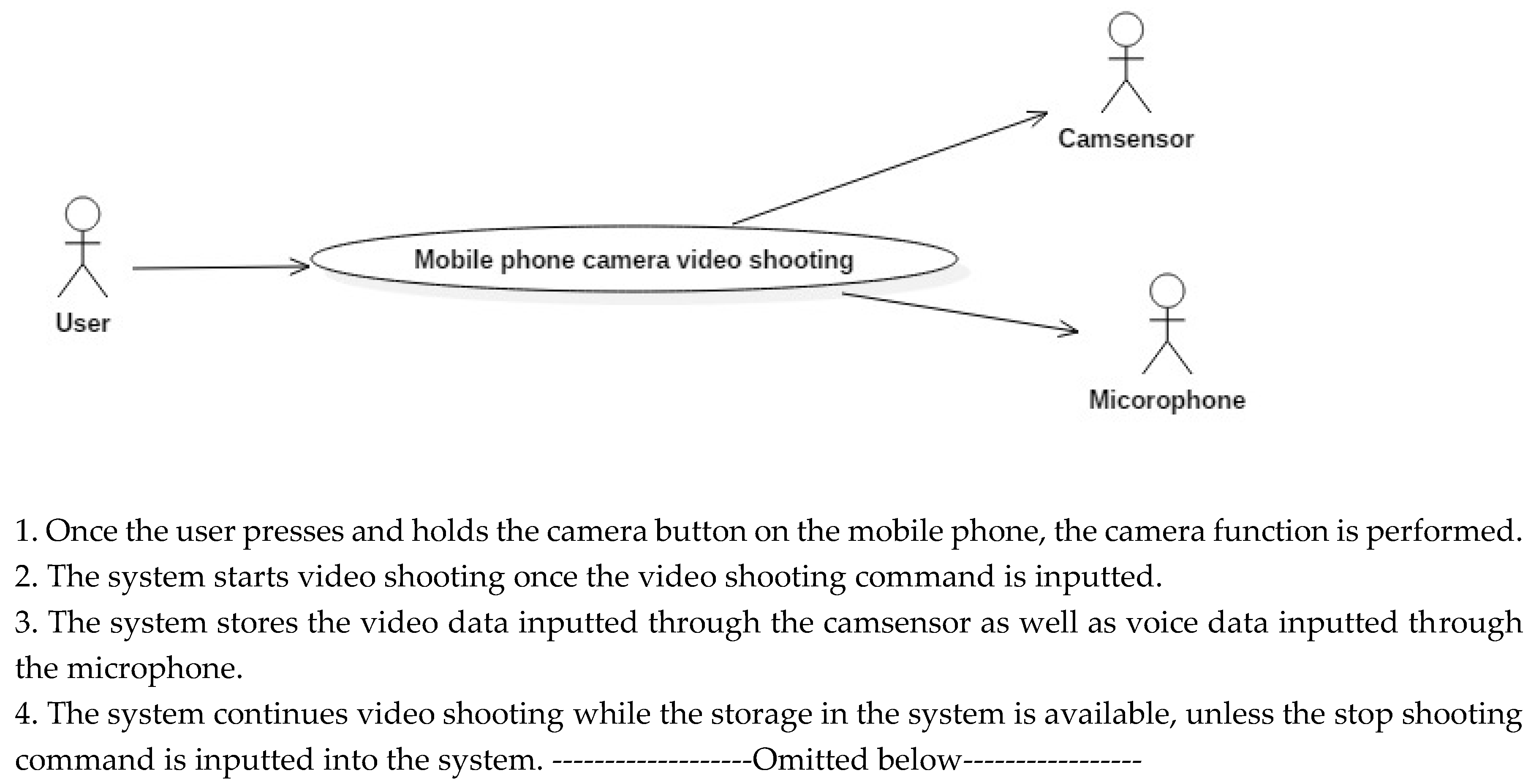
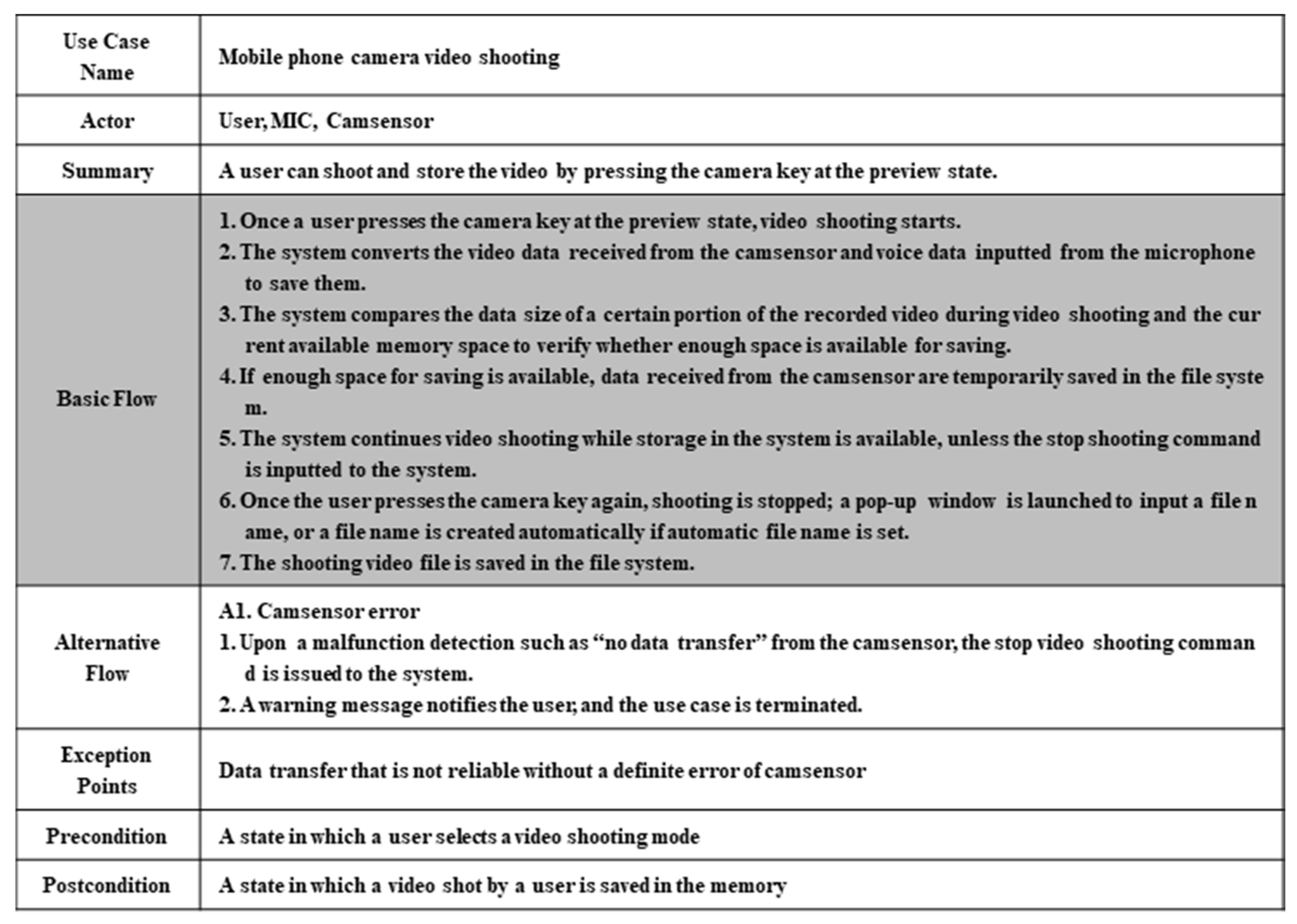
The use case model in Figure 1 is a specification describing a use case diagram in relation to camera video shooting among the software functions embedded in a mobile phone and the requirements of the system. The four sentences in the specifications in Figure 1 provide information that explains how to use the system from the user’s standpoint. However, from the viewpoint of embedded software developers, the information that can be extracted only includes the fact that an interface with internal components such as a camsensor and a microphone is needed, as suggested in Figure 1.
As described above, when a use case model is used for functional requirement specifications, the information provided to developers by the requirement specifications is not sufficient. To solve this problem, several studies have been proposed in which a state diagram is created in advance during business application development that identifies the system’s state, the behaviors of the system that correspond to events occurring inside and outside the system, and the state’s transitions; this information is reflected in the requirement specification. As the depth of the state diagram becomes deeper, it can provide a clearer implementation guide for developers. However, a method that identifies levels up to individual class levels inside the component, that is, a white box-based method that describes the requirements completely, experiences the problem that it requires excessive time in the initial phase of the software development cycle.
To overcome this problem, this study proposes a gray box-based requirement specification method that can provide an appropriate level of requirement specification depth in consideration of two issues: (1) the limitation of the information in the requirement specifications involved in the black box-based method; and (2) an excessive initial cost during the extraction of requirements in the white box-based method. Through the extension of the black box-based requirement specification method and the specification of collaboration between components that make up the system, developers are not provided with information for system implementation that was not previously expressed by use case specifications. To compensate for the time cost required to create state and sequence diagrams during the requirement analysis phase, a mechanism is suggested that generates requirement specifications automatically from the created model.
This paper is organized as follows. Section 2 investigates the trend of existing studies. Section 3 describes the embedded software requirement specification method, based on a gray box, proposed in this study. Section 4 discusses a development case for mobile phone camera sensor controllers using the automatic generation mechanism of the proposed specification. Finally, in Section 5, the contribution of this study is proven through verification of the effect of automatically-generated requirement specifications on the reduction of software development time.
2. Related Work
The gray box-based requirements in this paper are defined as requirements that describe interactions between the system and the environment where the system is utilized and the collaboration between internal components in the system that produces the interactions. According to this definition, model-based requirement specification methods that visualize internal operations in the system are deemed to belong to the category of “gray box-based requirement specifications.” Model-based methods refer to software development in which developers discover the main characteristics of the software and allow them to be independent from implementations at the lower-level source code [4]. One of the well-known model-based embedded software development methodologies is Gomaa’s Concurrent Object Modeling and architectural design method (COMET) [5]. In addition, the Object Modeling Technique (OMT) and Octopus methodologies [6] that model a system by differentiating structural, functional, and dynamic models provide guidelines for embedded software development.
There have been a number of studies on the application of the above general model-based specification methodologies to the embedded software domain [6,7,8,9]. In [6], a method that specified requirements based on the states of the system components was proposed, and [7] proposed concentrated specifications among three main components (controller, actuator, and sensor) of a controller that controlled the entire system. In contrast, [8] divided an analysis model into an E-Level, which represents a system’s external structure and behaviors, and an S-Level, which indicates a conceptual model of the inside of the system. This study showed the characteristics of using state diagrams and activity diagrams for specifications and analysis of the E-Level process. In [9], a relationship between an actual object and a system state was identified to specify the requirements of the embedded system, and then the relationship was made into a hierarchy to redefine the relationship with a state diagram.
However, although most results in these studies [6,7,8,9] proposed a requirement specification method for each development phase, as shown in Table 1, they did not provide a guideline for the degree of detail in each diagram needed to utilize the proposed modeling methodologies for the task of creating the requirement specifications. That is, they only vaguely mentioned that the degree of detail in the diagrams could be increased through iterative applications. Since they also did not support an automatic creation assistance mechanism for requirement specification, there were no compensation methods regarding the cost of the effort required for model creation.
3. Requirement Specification Methods for Embedded System Development Based on a Gray Box
As mentioned above, in previous studies, guidelines about the degree of detail needed during diagram creation for the requirement specification of embedded systems were not sufficient. Thus, this study proposes and divides into two depths the guidelines about the degree of detail.
Guideline 1: A state diagram of the controller that is identified in the uppermost level is created.
In accordance with the definition in [10], this study divided the components that make up a system into a controller, an actuator, and a sensor. Among these, the controller was assigned as the main actor of the system state, because it presides over the behavior of the sensor and the actuator and accounts for most of the implementation code during the embedded system development. The state diagram of the controller can also increase its depth while nesting continuously into inner space. However, the goal of the state diagram creation during the requirement analysis phase is to define the requirement specifications of the components that will be developed by developers rather than to obtain the design model that can be directly interlinked with the real development code. Thus, the state diagram needed for the requirement specification defines the behavior of the controller and limits the scope of creation as a top level of the state diagram.
Guideline 2: A sequence diagram, including the state transition information of the controller, is created.
The state diagram of the controller shows how the controller state transitions according to specific events. However, it cannot describe the order in which the events occur as time flows. Thus, it is necessary for developers to provide a sequence diagram that can describe the sequential development logic. It proposes an additional display of the controller’s state information identified in the state diagram prior to the basic sequence diagrams in the lifeline of the controller’s sequence diagram. While elements that express the state of objects were already added in UML 2.0 or later versions, a UML 1.4 version supported by most UML-related tools is used, and the state of the controller’s objects are represented using the note considering the high resistance against design tasks using UML by embedded developers.
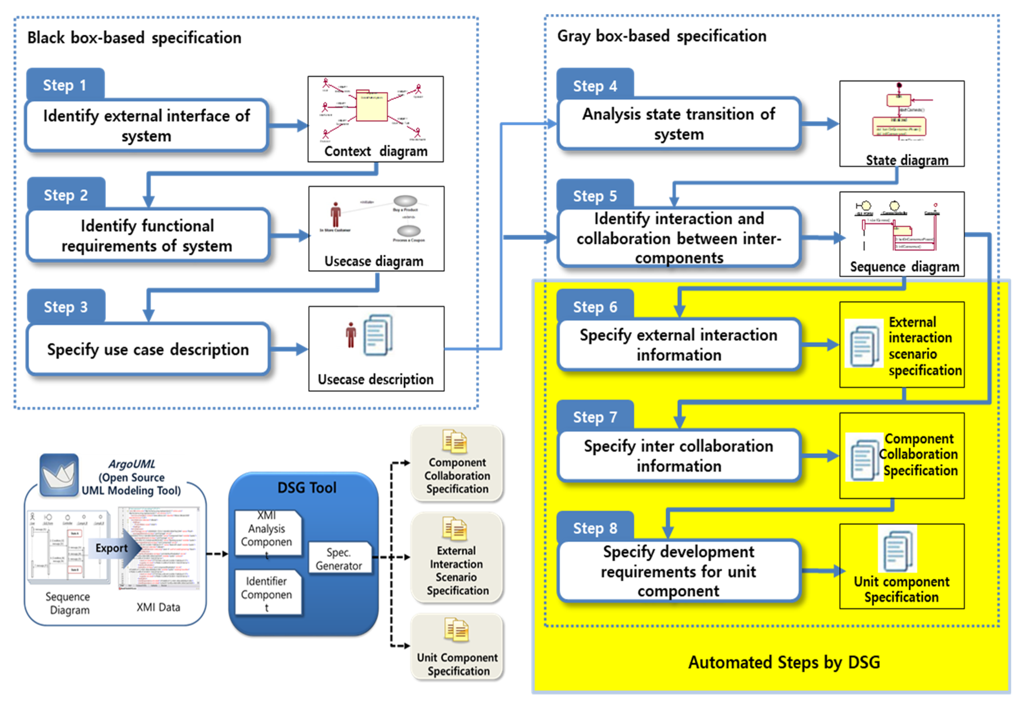
The development requirement specification method of embedded systems based on the gray box, including the above two core guidelines, consists of eight substeps, as depicted in Figure 2.
Steps 1–3 in the gray box-based requirement specification method are the same as those in the existing use case specification creation methods. Since the gray box-based method aims to complement the specifications of the inside of the system, which are not represented using specification methods via the black box, there is no change in the scope of the specification method covered by the existing use case specifications.
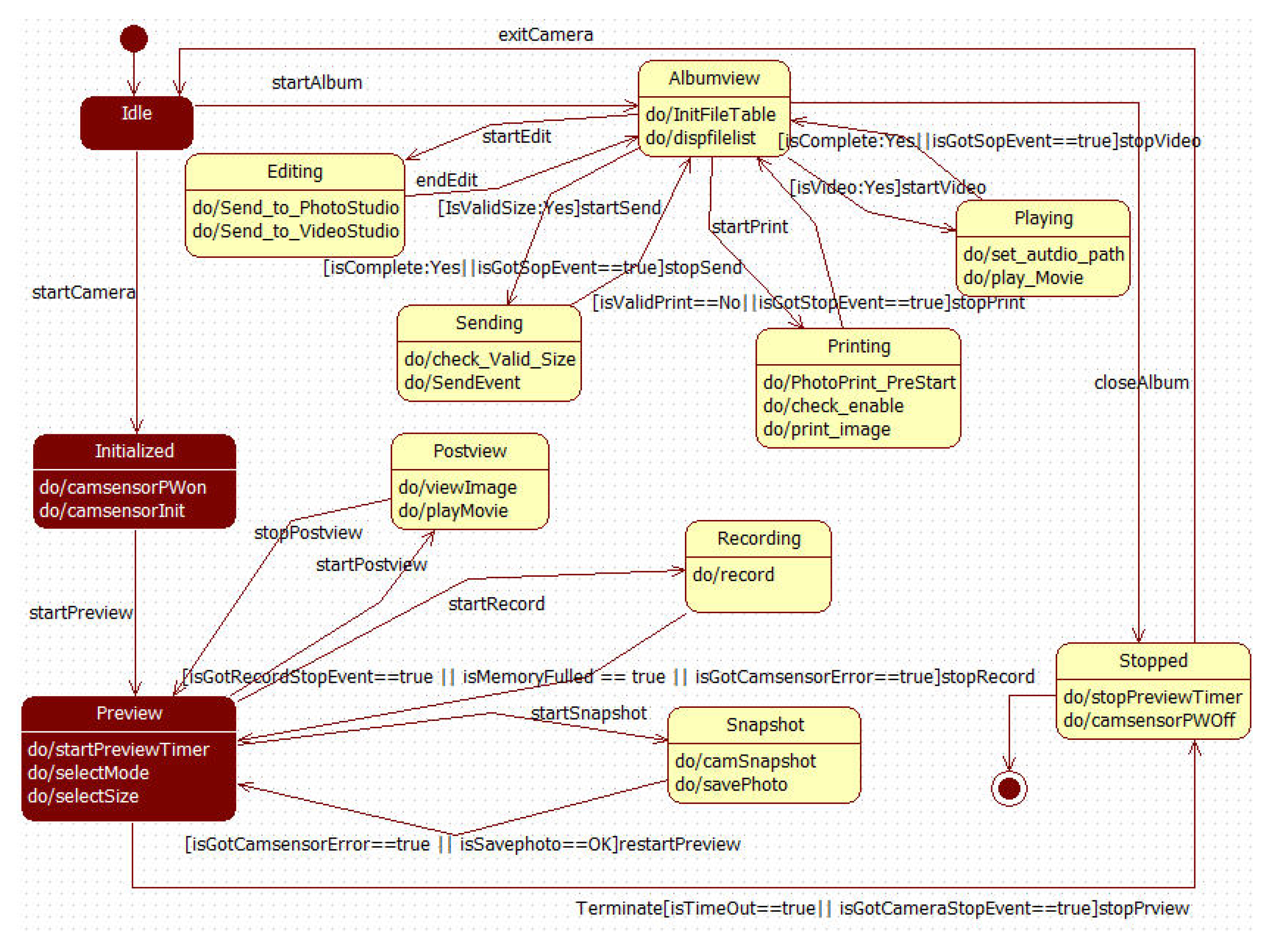
Utilizing the use case specifications created through Step 3, and using the domain knowledge in the corresponding embedded system, the state diagram of the controller is created in Step 4. According to Guideline 1, mentioned earlier, only the states of the uppermost level in the controller are identified. Figure 3 shows an example of state diagrams that identify only the uppermost level states in the CameraController.
Once all the states of the controller are identified in Step 4, Step 5 is the creation of a sequence diagram according to the flow of time to describe how the controller controls the actuator in response to stimulation sensed by the sensor or to outside events occurring through the user interface in Step 5. A part of the sequence diagrams related to the state transition, marked by the shade in Figure 3, can be found in Figure 4b. Steps 4 and 5 create an analysis model that corresponds to a source for the creation of requirement specifications, which can be generated overhead and newly compared to the creation of existing use case specifications.
To trade off the new overhead increase during the development process, a development specification generator (DSG) was developed as a tool to create the following three specifications automatically: External interaction scenario specifications made by the extraction of information in the already created UML-based analysis model, an intercomponent specification, and a unit component specification. The three specifications are explained in Section 4, using the example of a mobile phone camera, through the mapping process with the analysis model. The DSG identified the XML Metadata Interchange (XMI) structure of the UML model file and employed a method of mapping to each item, described in the three predefined specifications. The current implementation version supports the creation of specifications in the MS Word format from the open source StarUML. In addition to the tool’s reduction in development time, the time cost overhead required to create a part of the analysis model during the requirement analysis phase can be sufficiently compensated for through the three additional specifications providing information about the inside of the system for developers. The reduction effect of the development time due to the use of the created specifications is discussed through the experimental results in Section 5.
4. Case Study: Mobile Phone Camera Sensor
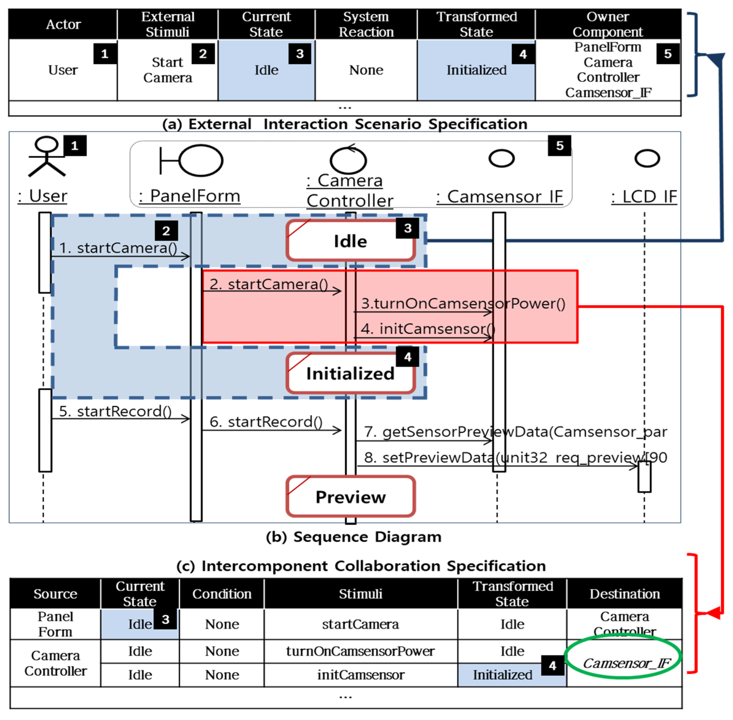
To evaluate the practical applicability of the method proposed in this study, it was applied to the development of a camera function module in mobile phone software that was under development in actual work sites. Figure 4 shows some of the analysis model and a mechanism that extracts the three requirement specifications automatically, defined by the process through the analysis model. Figure 4b shows a sequence diagram created according to the guideline. The information about the state of the already-identified CameraController is marked in the lifeline of the sequence diagram. As shown in Figure 4b, the message startCamera(), generated through a specific action in the “Idle” state PanelForm of the system by the user, is transferred to the CameraController. The CameraController sequentially transfers the messages turnOnCamsensorPower() and initCamsensor() internally in the system to Camsensor_IF to perform the function that corresponds to the command. As a result, the state of the system transitions from “Idle” to “Initialized.”
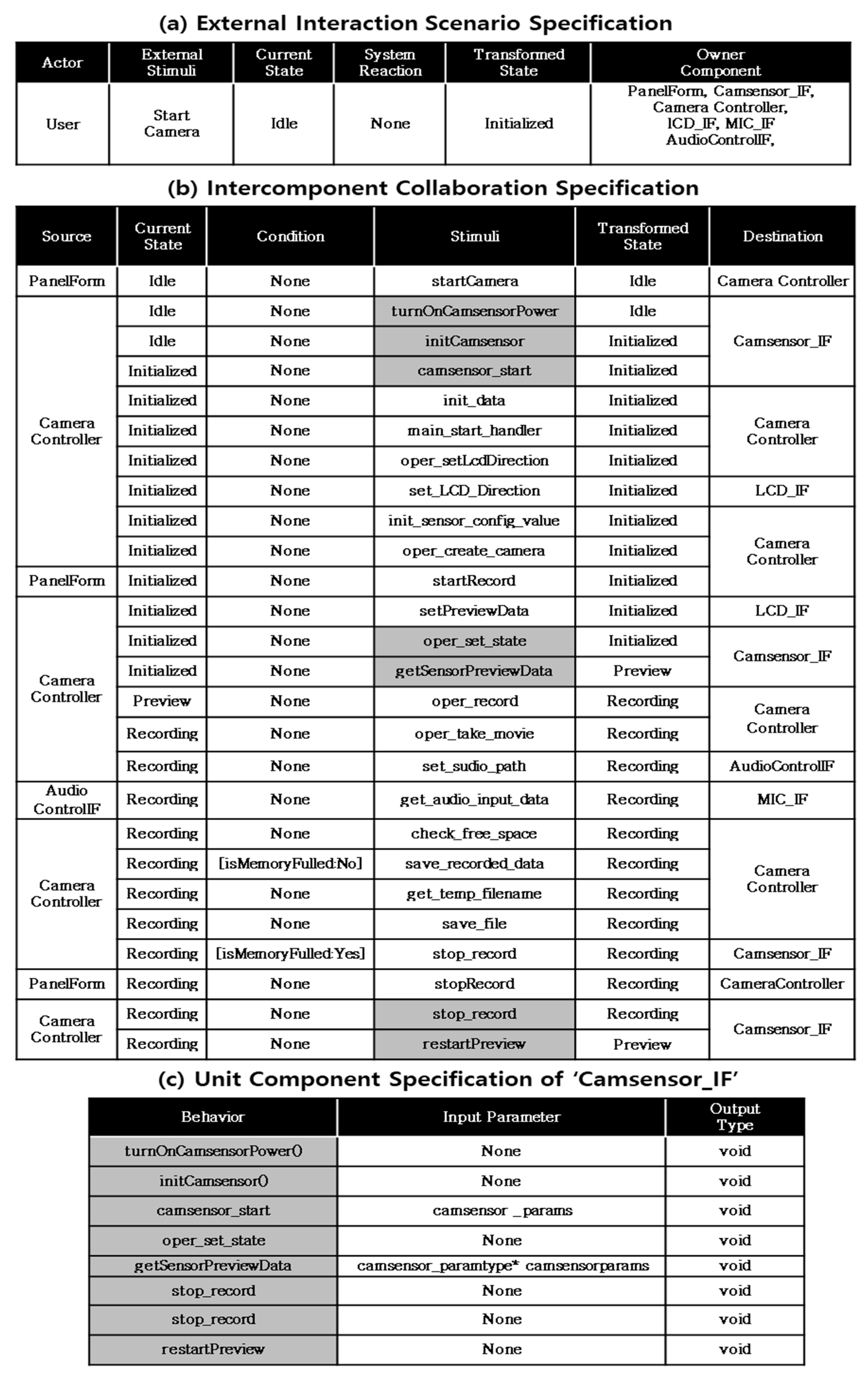
Once the created analysis model is inputted to the DSG, the DSG reads the XML that contains the information for the sequence diagram through the mapping process depicted in Figure 4. It outputs the results to appropriate items in the predefined Word template, thereby automatically creating the requirement specification that defines the internal and external interactions of the system. The information marked by the dotted lines in Figure 4b is mapped to the first row in the external interaction scenario specification in Figure 4a. That is, startCamera() transforms the state of the system from “Idle” to “Initialized” by the external stimulation, and the related components are PanelFORM, CameraController, and Camsensor_IF. The intercomponent collaboration specification in Figure 4c describes the collaboration and state transition in the system inside until Figure 4a occurs, and the content in the area marked by the solid line in Figure 4b is mapped to the intercomponent collaboration specification. The components corresponding to the destination of the message, located in the far right column in Figure 4c, refer to components whose mission is to implement the message. In other words, a set of messages whose destination is the same corresponds to the Application Programming Interface (API) set that should be implemented by specific components. Thus, operations whose destination is the same in Figure 4c can be collected, and unit specifications of the components that correspond to the destination can be extracted. An example of the unit component specification is shown in Figure 6c. In contrast with the other two specifications, the unit component specification is distributed to developers as the development specification. Thus, accurate header information about operations in each of the APIs is stated.
Figure 5 shows the existing use case specification and Figure 6 shows the specifications automatically created by the DSG, based on the analysis model as a source, according to the guidelines proposed in this study. Figure 6a–c show the content that corresponds to the basic event flow among the contents in the “video shooting” use case specification. As shown in the figures, the use case specification concentrates on descriptions of the interaction between the system and the environment, whereas the intercomponent collaboration specification in Figure 6b shows the collaborations between the software components and the state changes inside the system until the external interaction occurs. The specification in Figure 6b has the advantage that not only can it be a source of the unit component specification in Figure 6c, as explained above, but it can also be utilized as a test case for integration between components after system implementation.
5. Verification and Conclusions
A comparison between Figure 1, which shows the video shooting use case specification for the development of a mobile phone camera sensor using the black box-based method described in the introduction, and Figure 4, which shows the requirement specification related to video shooting that is created or automatically generated using the gray box-based method proposed in this study, verifies that the amount of additional information provided through the proposed method can be measured in a fragmentary way.
This study conducted an experiment with 38 fourth-year undergraduate students to measure the effect on the improvement in the productivity of a quantitative increase in the requirement specifications for the development of an embedded system during actual embedded software development. Considering that embedded software developers in the software industry have a low overall level of knowledge about UML, the fourth-year undergraduate students were selected because they were capable of development language programming to some extent, but their level of knowledge about UML was relatively low. The target system was a function of “detection and bypassing obstacles and intruders during robot running” of the patrolling robot. The patrolling robot system is also one of the embedded system categories, consisting of a sensor, a controller, and an actuator.
This study divided the participatory students into two groups. In order not to make a meaningful difference in the average capability of the two groups, I organized each team with reference to the grades of each student in the programming subject. While the use case diagrams and specifications of the existing black box-based requirement specifications were provided to both group 1 and group 2, the automatically-generated requirement specifications proposed in this paper were provided only to group 2. Then, I had each student in each group implement the function of "detection and bypassing obstacles and intruders during robot running", according to the different requirement specification artifacts. The time taken for each development phase was filled in, in the time recording log (C16) sheet of the personal software process (PSP), for two weeks [11].
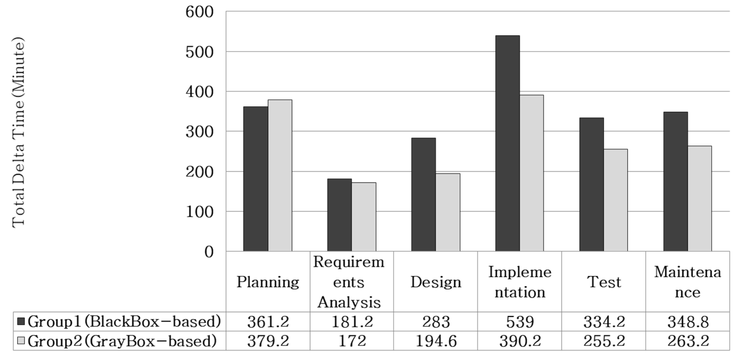
The results showed that group 2 reduced the development time in all phases except for the planning–establishment phase, as shown in Figure 7. In particular, group 2 shortened the time of the design phase by about 31% and of the implementation phase by about 28%, compared to group 1. To verify that the reduction effect between groups was not caused by a difference in individual abilities, regression analysis was conducted with individual academic grades and development times. The analysis results showed that the determination coefficient R-Square was 0.01, which verified that the effect of individual abilities was not significant in the reduction in development time. Thus, group 2’s reduction effect on development time throughout the design, implementation, test, and maintenance phases, as shown in Figure 7, can be analyzed as being due to the additional requirement specification method proposed in this study.
This study proposed a guideline for developers by setting the optimum level of requirement specification that can be utilized as a development convention in order to overcome the limitation of information that occurs when using use case specifications for documenting functional requirements of embedded software. The proposed gray box-based requirement specification method has the same context as the gray box testing technique [12] in order to leverage the pros of the white box testing and the black box testing approaches. The study also developed a tool that can extract requirement specifications automatically from the analysis model in order to compensate for the effort needed to create the analysis model during the requirement analysis phase, and it applied the tool to real system developments. This study also visibly and quantitatively proved the effectiveness of the proposed method through an experiment with actual embedded system development.
However, like the use case model, the proposed method guides the specification of functional requirements among the taxonomy of software requirements. To develop highly-qualified embedded software, the specification of non-functional requirements (e.g., performance, usability, reliability, security, etc.) is as important as the functional requirements. I am currently working on finding a more effective way than the existing models to extend the proposed method to the non-functional requirements of embedded software.
Funding
This research received no external funding.
Conflicts of Interest
The author declare no conflict of interest.
References
- Lee, E.A. What’s ahead for embedded software? Computer 2000, 33, 18–26. [Google Scholar] [CrossRef]
- Booch, G.; Rumbaugh, J.; Jacobson, I. The Unified Modeling Language User Guide, 2nd ed.; Addison-Wesley Professional: Boston, MA, USA, 2005; ISBN 0321267974. [Google Scholar]
- What’s Wrong with Use Cases? Available online: https://pythonconquerstheuniverse.wordpress.com/2009/10/17/whats-wrong-with-use-cases/ (accessed on 15 January 2019).
- Douglass, B.P. Real-Time UML: Developing Efficient Objects for Embedded Systems; Pearson Education: London, UK, 1999; ISBN 0201657848. [Google Scholar]
- Gomaa, H. Designing concurrent, distributed, and real-time applications with UML. In Proceedings of the 28th international conference on Software engineering(ICSE ’06), Shanghai, China, 20–28 May 2006. [Google Scholar]
- Leveson, N.G.; Hildreth, H.; Reese, J.D. Requirements Specification for Process-Control Systems. IEEE Trans. Softw. Eng. 1994, 20, 684–707. [Google Scholar] [CrossRef]
- Lattemann, F.; Lehmann, E. A methodological approach to the requirement specification of embedded systems. In Proceedings of the 1st IEEE International Conference on Formal Engineering, Hiroshima, Japan, 12–14 November 1997. [Google Scholar]
- Lavi, J.Z.; Kudish, J. Systems modeling & requirements specification using ECSAM: A method for embedded computer-based systems analysis. In Proceedings of the 11th IEEE International Conference and Workshop on the Engineering of Computer-Based Systems (ECBS 2004), Brno, Czech Republic, 27 May 2004. [Google Scholar]
- Glinz, M. Statecharts For Requirements Specification—As Simple As Possible, As Rich As Needed. In Proceedings of the 24th International Conference on Software Engineering (ICSE 2002), Workshop: Scenarios & State machines, Orlando, FL, USA, 19–25 May 2002. [Google Scholar]
- Broy, M.; Stauner, T. Requirements engineering for embedded systems. In Proceedings of the FemSys’97; Available online: http://citeseerx.ist.psu.edu/viewdoc/summary?doi=10.1.1.10.5614&rank=1. (accessed on 15 January 2019).
- Humphrey, W.S. Introduction to the Personal Software Process; Addison Wesley: Boston, MA, USA, 1997; ISBN 0201548097. [Google Scholar]
- Acharya, S.; Pandya, V. Bridge between Black Box and White Box—Gray Box Testing Technique. Int. J. Electron. Comput. Sci. Eng. 2013, 2, 175–185. Available online: http://citeseerx.ist.psu.edu/viewdoc/download?doi=10.1.1.303.4479&rep=rep1&type=pdf (accessed on 15 January 2019).
Figure 1.
Use case model describing “mobile phone video shooting”.

Figure 2.
The embedded system analysis and development requirement specification process.

Figure 3.
State diagram in the camera controller.

Figure 4.
Automatic creation process of development requirement specification from the gray box-based analysis model.
Figure 4.
Automatic creation process of development requirement specification from the gray box-based analysis model.

Figure 5.
The “Mobile phone camera video shooting” use case specification.

Figure 6.
(a) External collaboration scenario specifications, (b) Intercomponent collaboration specifications, (c) Unit component specification that corresponds to the “Mobile phone camera video shooting” use case.
Figure 6.
(a) External collaboration scenario specifications, (b) Intercomponent collaboration specifications, (c) Unit component specification that corresponds to the “Mobile phone camera video shooting” use case.

Figure 7.
Results of comparison experiments on productivity during embedded software development.


© 2019 by the author. Licensee MDPI, Basel, Switzerland. This article is an open access article distributed under the terms and conditions of the Creative Commons Attribution (CC BY) license (http://creativecommons.org/licenses/by/4.0/).
Share and Cite
MDPI and ACS Style
Park, S. Software Requirement Specification Based on a Gray Box for Embedded Systems: A Case Study of a Mobile Phone Camera Sensor Controller. Computers 2019, 8, 20. https://0-doi-org.brum.beds.ac.uk/10.3390/computers8010020
AMA Style
Park S. Software Requirement Specification Based on a Gray Box for Embedded Systems: A Case Study of a Mobile Phone Camera Sensor Controller. Computers. 2019; 8(1):20. https://0-doi-org.brum.beds.ac.uk/10.3390/computers8010020
Chicago/Turabian StylePark, Soojin. 2019. "Software Requirement Specification Based on a Gray Box for Embedded Systems: A Case Study of a Mobile Phone Camera Sensor Controller" Computers 8, no. 1: 20. https://0-doi-org.brum.beds.ac.uk/10.3390/computers8010020
Note that from the first issue of 2016, this journal uses article numbers instead of page numbers. See further details here.