Article

Testing Metal–Organic Framework Catalysts in a Microreactor for Ethyl Paraoxon Hydrolysis

by
Palani Elumalai
1,
Nagat Elrefaei
2,
Wenmiao Chen
1,
Ma’moun Al-Rawashdeh
2,* and
Sherzod T. Madrahimov
1,*
1
Chemistry Department, Texas A&M University at Qatar, Doha, Qatar
2
Chemical Engineering Department, Texas A&M University at Qatar, Doha, Qatar
*
Authors to whom correspondence should be addressed.
Submission received: 17 September 2020 / Revised: 30 September 2020 / Accepted: 1 October 2020 / Published: 9 October 2020
(This article belongs to the Special Issue MOFs for Advanced Applications)

Abstract

:
We explored the practical advantages and limitations of applying a UiO-66-based metal–organic framework (MOF) catalyst in a flow microreactor demonstrated by the catalytic hydrolysis of ethyl paraoxon, an organophosphorus chemical agent. The influences of the following factors on the reaction yield were investigated: a) catalyst properties such as crystal size (14, 200, and 540 nm), functionality (NH2 group), and particle size, and b) process conditions: temperature (20, 40, and 60 °C), space times, and concentration of the substrate. In addition, long-term catalyst stability was tested with an 18 h continuous run. We found that tableting and sieving is a viable method to obtain MOF particles of a suitable size to be successfully screened under flow conditions in a microreactor. This method was used successfully to study the effects of crystal size, functionality, temperature, reagent concentration, and residence time. Catalyst particles with a sieved fraction between 125 and 250 µm were found to be optimal. A smaller sieved fraction size showed a major limitation due to the very high pressure drop. The low apparent activation energy indicated that internal mass transfer may exist. A dedicated separate study is required to assess the impact of pore diffusion and site accessibility.

1. Introduction

In the early 1990s, microreactors and flow chemistry emerged and established themselves as powerful tools for exploratory research, piloting, and industrial production. Due to the characteristically small diameter of the reaction channel in the micron-to-millimeter range, a very high surface-to-volume ratio is realized and mixing and heating are significantly accelerated, which enable demanding chemical processes to operate safely and under closely controlled conditions [1,2]. The very low holdup of the reaction volume ensures an entirely new level of inherent safety in the process, as evidenced in the application of this technology to toxic or explosive reactions [3,4,5,6]. The narrow residence time distribution approaching that of an ideal plug flow reactor [7,8,9] makes it beneficial for maximizing the selectivity of parallel and sequential reactions and in the synthesis of monodispersed nanoparticles [10,11,12]. Running reactions under flow microconditions enables much better quality control compared to batch reactions, as processes can be run under continuous monitoring using online sensors. As such, flow microreactors are ideal for fully automated systems to synthesize, screen, and optimize chemical research [13,14,15].
Metal–organic frameworks (MOFs) are an emerging class of porous materials constructed from metal-containing secondary building units (SBUs) and organic linkers [16]. The highly porous cavities decorated with functional ligands and active metal SBUs produce MOFs with exceptional potential for the fabrication of a variety of heterogeneous catalysts. For example, the hydrolysis of chemical warfare agents (CWAs) and simulants with highly stable Zr(IV)-based MOFs such as UiO-66, NU-901, NU-1000, and MOF-808 has been explored because of their ultrahigh stabilities in aqueous solvents. Using Lewis acidic zirconium clusters as active sites has also been studied [17,18,19]. Although MOF or MOF-based composite catalysts have been proven to be effective for the degradation of CWAs, most examples were tested in batch conditions in basic solutions. In general, there are few examples of catalytic testing of MOF-based catalysts in flow reactors as shown in Scheme 1 [20,21].
Catalyst testing in flow microreactors has many advantages over traditional solid catalyst testing in batch reactors [20]. First, many operating parameters such as temperature, pressure, and feed concentrations can be easily and quickly varied in flow microreactors, which provide an insight into the reaction mechanism and kinetics; second, consumption of chemicals and waste production is significantly reduced; and third, it enables easy testing of catalyst reusability, and catalyst stability under reaction conditions via long-term testing on a stream and changing the feed purity. Additionally, flow microreactors enable the study of the direct leaching of the active metal or organic components by chemical analysis of the filtrate and effluent. Considering the potential of MOFs as catalytic materials and flow microreactors as a powerful tool for catalyst testing, studying how to use MOF catalysts in a flow microreactor is valuable for future research, especially during the exploration and screening phase.
A major limitation to loading the as-synthesized MOF catalyst powder in the flow microreactor is the small particle size, ranging from nanometers up to a few micrometers, which results in a very high pressure drop. To eliminate this drop, the catalyst particles must be enlarged to a sufficient size. Several compounding methods have been proposed in the literature to enlarge MOF catalyst particle size. These include coating the catalyst on the wall of the reaction channel, using a monolith, producing catalyst microfibers, or using 3D printing to construct smart designs [22,23]. Each of these concepts has its own advantages and specific challenges. Although these are promising solutions for final commercial applications, testing catalysts in powder form is sometimes inevitable in the research stage. This is especially true at the initial exploratory phase of research, in which determining intrinsic reaction kinetics is essential, the quantities of available catalysts are small, and supply is limited. The intrinsic kinetics are better tested without the presence of binders, as they could affect activity and catalyst particle size needs to remain small to avoid mass and heat transfer limitations.
The most common method used to increase catalyst particle size is tableting the as-synthesized powder via mechanical compression, followed by crushing and sieving the tablet to obtain particles of the desired size. This is advantageous and easy as no binding material or additional complex treatment steps that could affect the catalyst properties are needed. The only concern is that applying mechanical compression to MOFs could cause a decrease in surface area due to destruction of the crystalline structure [24,25,26]. Some MOFs collapse when submitted to mechanical compression beyond a certain pressure [27]. The zirconium metal–organic framework UiO-66 chosen for this study possesses exceptional mechanical stability in a highly porous system and can be processed through the pelleting, crushing, and sieving procedure without significant mechanical damage [28,29,30].
The aim of this paper is to demonstrate the capability of MOFs as a catalytic material in a flow microreactor. The emphasis is mainly on demonstrating if increasing particle size by tableting and crushing is a viable option for efficient catalyst screening and testing. To this end, the detoxification of ethyl-paraoxon (pesticide) through a hydrolysis reaction was studied in the loaded capillary flow reactor. Several parameters were tested including different MOF crystal sizes and functionality. The operating temperature, concentration, and residence time were also tested. Finally, the catalyst was tested for a long period of time under continuous flow to check its stability.

2. Results

2.1. MOF Synthesis, Loading Sieved Catalysts in the Capillary Flow Reactor and Analysis of the Catalyst Bed

All reagents were purchased from commercial sources and used without further purification. UiO-66-14nm (1), UiO-66-200nm (2), UiO-66-540nm (3), UiO-66-NH2-14nm (4), and ethyl-paraoxon were synthesized according to literature procedures (see the Supplementary Materials) [31,32].
To prepare the particles suitable for microreactor loading, the as-synthesized MOF powders were tableted for 5 min using a bench-top tablet press at 10 tons for a tablet diameter of 13 mm. The tablet was then crushed using a hand mortar and sieved. Particle sizes in the sieved fraction ranged from 45 to 125 µm and from 125 to 250 µm were collected for reactor loading. The process was repeated several times until a sufficient amount of powder in the targeted ranges was obtained. The sieved catalyst was then loaded into the 15 cm capillary tube with an internal diameter of 1.55 mm. The capillary loaded with the catalyst was secured from both sides by inserting glass wool. A quantity of catalyst ranging from 35 to 60 mg was loaded into each capillary, resulting in loaded catalyst lengths of 28 to 37 mm. The six capillary tubes prepared according to this method are summarized in Table 1. For example, reactor 1a represents the capillary tube loaded with a 30 mm catalyst bed of 35 mg of particles, with particle size fractions between 125 and 250 µm and prepared with UiO66_14nm and UiO66 MOF with an average crystal size of 14 nm.
Table 2 presents the Langmuir surface area of as-synthesized MOF samples after tableting and sieving and a sample analyzed after the reaction. The surface area measurements for as-synthesized MOF was similar to what is reported in the literature [33,34]. The surface area of tableted MOF 1a significantly decreased compared to as-synthesized UiO66, 1, although no damage to the crystal structure was incurred as observed by the powder X-ray diffraction (PXRD) patterns, which are shown in the Supplementary Material. A similar decrease in the surface area after the tableting and sieving process was also observed for catalyst 4a. A significant decrease in surface area for catalysts 2a and 3a, with larger crystal sizes, has also been previously reported [35]. We also observed that the surface area of catalyst 1aAR recovered after the reaction decreased compared to the surface area measured before loading, which may be due to the substrate or product being trapped in the pores of the catalyst during the flow reaction. The as-synthesized, tableted, and sieved catalysts were also analyzed by transmission electron microscopy (TEM), scanning electron microscopy (SEM), and energy dispersive X-ray analysis EDX-elemental mapping and PXRD techniques. Despite the observed decrease in the surface area, these measurements showed that the structure and integrity of the particles were preserved during the flow reactions, in agreement with previous observations on the mechanical and chemical stability of UiO66 MOFs. Detailed TEM, SEM, and EDX-elemental mapping and Brunauer-Emmett-Teller (BET) and PXRD analysis data are provided in the Supplementary Materials, Figures S1–S17.

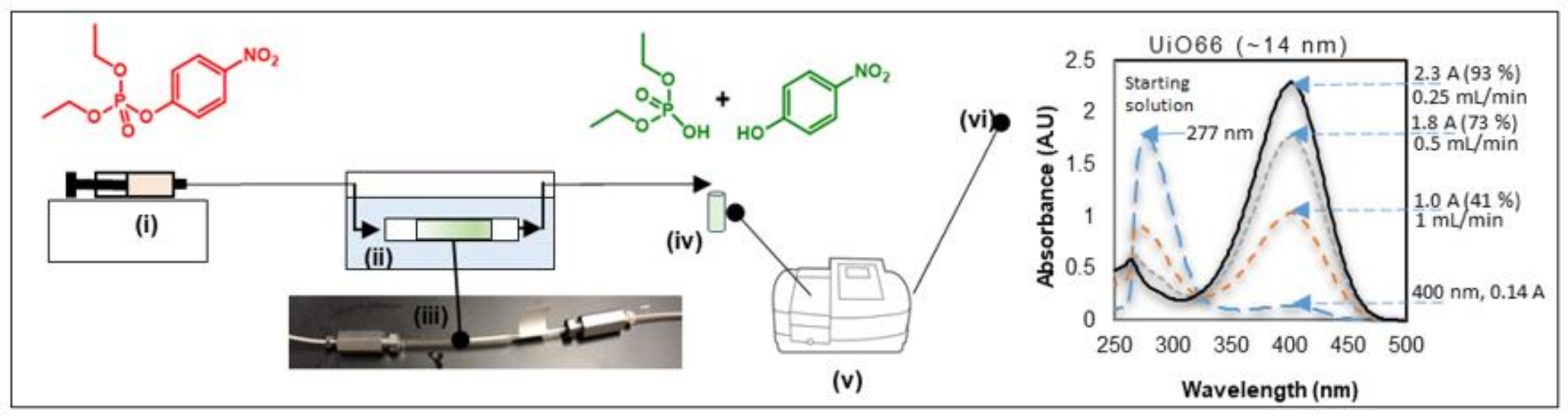
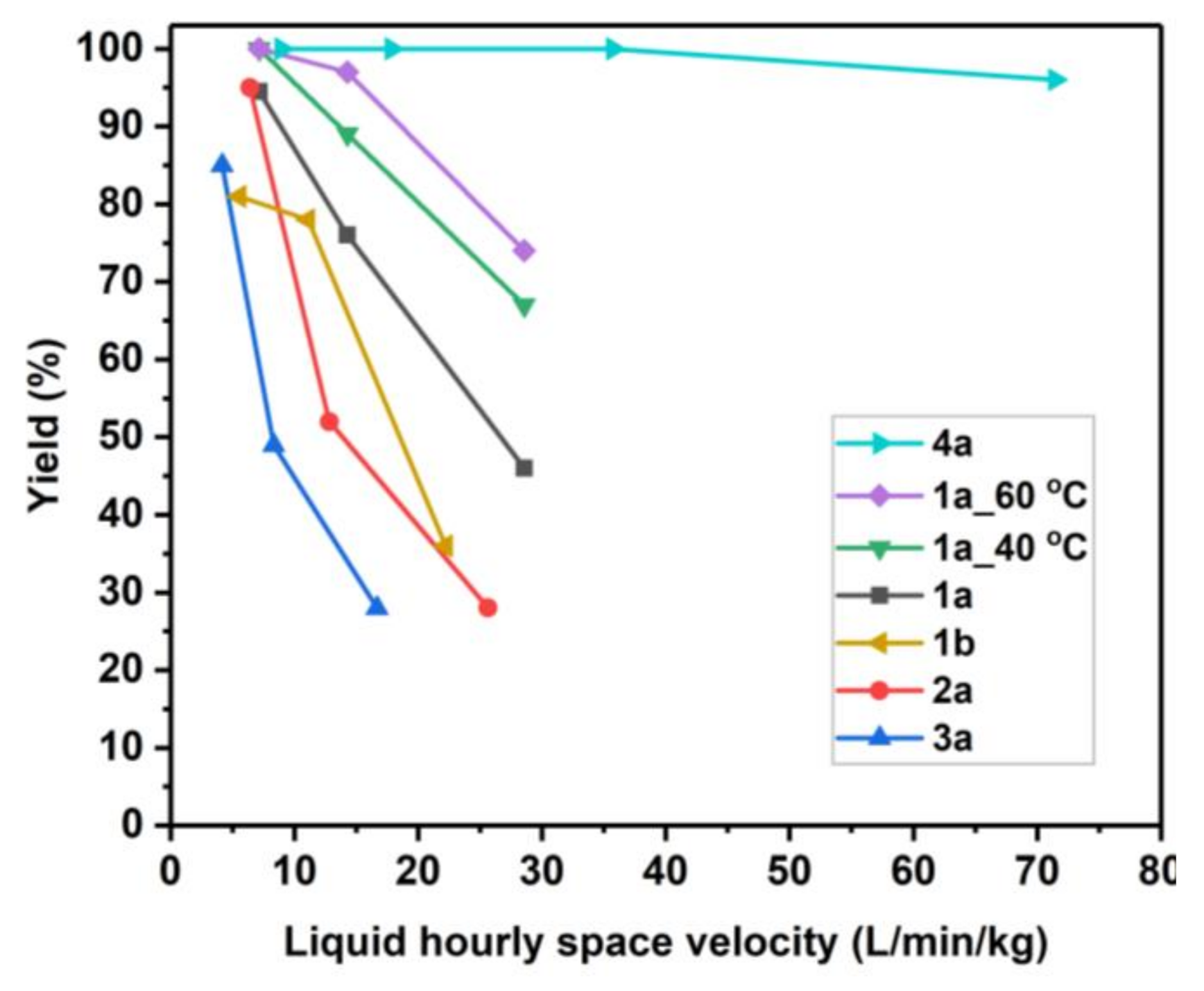
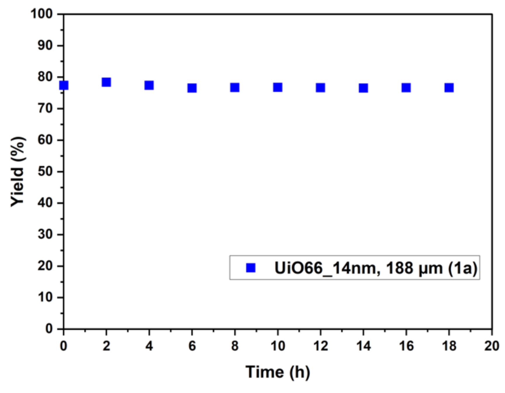
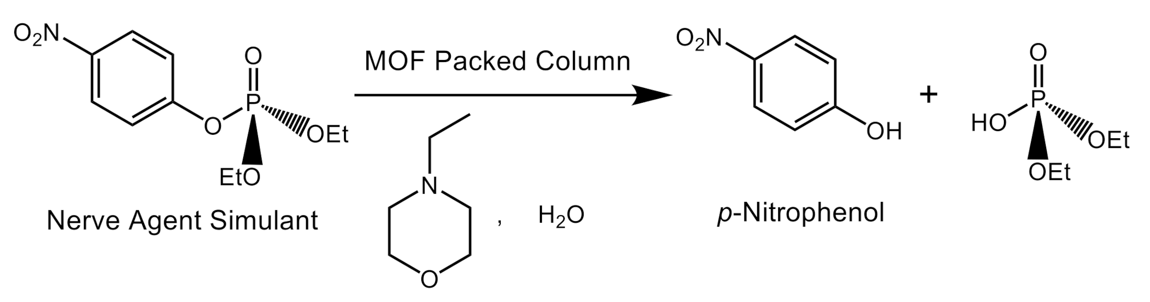
2.2. Catalyst Testing for Ethyl Paraoxon Hydrolysis and Analysis

The experimental setup for the flow microreactor is shown in Figure 1. It consisted of a syringe pump that enabled the microreactor flow rates to be controlled. The 12 mL syringe was filled with the buffer solution of the 3.4 g/L (0.012 mol/L) organophosphorus agent and connected to the reactor via capillary tubes. The reactions were conducted at different temperatures by placing the microreactor in a heated water bath. The products were collected in small batches of less than 0.2 mL and the yields were measured offline via UV spectroscopy by comparing the absorbance of p-nitrophenoxide at 405 nm in the product mixture to the calibration curve. The calibration curve and further details about the UV analysis are provided in the Supplementary Materials, Figure S18.
After the catalyst was loaded, the loaded microreactors were tested for a pressure drop at three flow rates of 0.5, 1, and 1.5 mL/min using water. A very high pressure drop was observed in reactors 1b and 4b (Table 1) with sieved particle sizes between 45 and 125 µm that resulted in catalyst particle movement and the formation of a segregated channeled catalyst bed. For reactors loaded with larger sieved particle sizes of 125 to 250 µm, the catalyst bed was stable and demonstrated reproducible performance. MOF catalyst particles larger than 125 µm were therefore tested in catalytic runs in the capillary flow reactor.
Figure 2 summarizes all of the flow reactions conducted in this study. Results are presented in terms of yield versus liquid hourly space velocity (LHSV, flow rate divided by amount of loaded catalyst). For reactor 1a tested in an ambient temperature, yields in excess of 93% in less than 15 s were obtained, corresponding to an LHSV of 7.1 L/min/kg (a liquid flow rate of 0.25 mL/min). The yield decreased linearly as the flow rate increased. A good level of reproducibility was observed, with a yield fluctuation of ±2%. Reactor 1b, loaded with the same MOF catalyst but a smaller particle size (with a sieved fraction between 45 and 125 µm), demonstrated a significantly lower yield (see Figure S19 in Supplementary Materials). As mentioned earlier, the catalyst bed was not stable for sieved fractions smaller than 125 µm, resulting in segregation and channeling because of the very high pressure drop.
UiO66 crystal sizes of 14, 200, and 540 nm, 1a, 2a, and 3a, respectively, were tested, as shown in Figure 2. These MOFs were all prepared according to the procedure described by Morris et al., in which the average MOF particle size was controlled by the amount of acid used in the synthesis, whereby using a larger amount of acid in the MOF synthesis leads to the formation of MOFs with larger crystal size [31]. Increasing the crystal sizes decreased the yield at a given LHSV. This is consistent with the results reported in the literature. Since the reaction is considered to occur at the surface of the crystal, catalysts with a smaller crystal size will have more surface area accessible and more activity [36]. The yield trend for larger crystal sizes of 200 nm (2a) and 540 nm (3a) was different than that of 1a, indicating that other factors influence the activity. It could be that when crystal size increases, the interparticle pore structure in the crystal aggregate is altered to reduce the accessibility of the catalytically active sites. The effect of the –NH2 group in the MOF linker on catalyst activity was also tested. As expected, the presence of the –NH2 group in the MOF resulted in a significant increase in catalyst activity, in agreement with prior reports [37].
The long-term stability of the catalyst under the flow conditions was tested by running the reference catalyst in reactor 1a for 18 h at a liquid flow rate of 0.5 mL/min at 20 °C with periodic sampling, as shown in Figure 3. As can be seen in the figure, catalyst activity remained level throughout the testing period. This excellent stability over time suggests good potential for future practical applications of MOF catalysts in flow reactors.

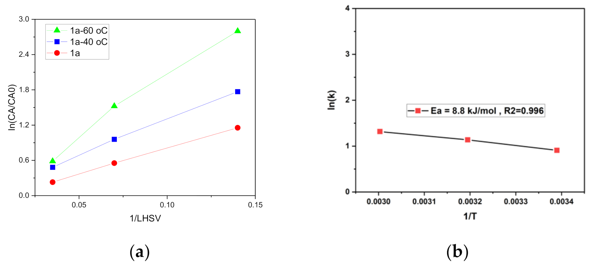
2.3. Catalyst Kinetic Evaluation Based on Initial Rates

The effect of temperature on catalyst performance is shown in Figure 2 for reactor 1a. The flow microreactor enabled multiple space times and temperatures to be easily tested. This is a significant advantage over batch reactors where each condition requires a separate reaction setup. The kinetic measurements of catalyst 1a were found to nicely fit first-order reaction kinetics, as shown in Figure 4. Using the Arrhenius plot, the apparent activation energy was estimated as 8.8 kJ/mol. Although the response to temperature is evident in Figure 4, the process may be limited by internal mass transfer limitation, as the apparent activation energy (Ea) value could be considered low [38]. To provide conclusive answers on mass transfer limitations, a dedicated study in which various particle size ranges and loading lengths are tested at different temperatures is required.

3. Materials and Methods

3.1. Materials

All air- or water-sensitive reactions were carried out in a nitrogen atmosphere using oven-dried glassware. All syntheses of oven-based UiO66 and the derivative MOFs were carried out in explosion-proof HERAtherm OMS-100 (Thermo Fisher Scientific, Waltham, MA, USA) ovens that had been pre-heated to a specific temperature. All sonication was carried out with a Fisher Scientific Ultrasonic Cleaner FS60 (Thermo Fisher Scientific, Waltham, MA, USA). Anhydrous solvents in Sure/Seal™ bottles were purchased from the Aldrich Chemical Company (Milwaukee, WI, USA) and used as received inside a nitrogen-filled KIYON Glovebox (Korea Kiyon Glovebox System, Seoul, South Korea). All other reagents were purchased from the Aldrich Chemical Company (Milwaukee, WI, USA) and used without further purification unless otherwise noted.
Powder XRD spectra were collected using a Rigaku Ultima IV multipurpose X-ray diffractometer equipped with Cu-Kα radiation and a fixed monochromator. The XRD was operated at 40 KV and 40 mA and a fixed time-scan mode with a 0.02-degree step width and 1 s/step count time used for data collected from 5 to 90 degrees.
For scanning electron microscopy/energy dispersive X-ray spectroscopy (SEM/EDS), an FEI Quanta 400 environmental scanning electron microscope was used to collect high-resolution SEM images. The SEM was operated at an acceleration voltage of 30 KV and the working distance was 6.5 mm. An EDAX Apollo EDS system was used for EDS signal collection and analysis.
Transmission electron microscopy images were collected using a Thermo Fisher company TalosF200x model with a super X EDS system. Powder 1 or 2 was dispersed in isopropyl alcohol and sonicated for about 5 min. An amount of 20 μL of the dispersed solution was dropped over a 300 mesh copper/lacey carbon grid and dried at room temperature for TEM analysis.
For N2 gas sorption analysis, the MOF samples for analysis were heated under vacuum overnight at 150 °C to remove the solvents trapped within the pores prior to analysis. Following this, an ~50 mg sample was transferred to pre-weighed sample tubes and degassed at 150 °C for 3 h by a Micromeritics Flow prep 060 sample degassing system. After degassing, the MOF sample tubes were re-weighed to obtain the mass for the samples. Sorption data with the Brunauer−Emmett−Teller method (BET) and the Langmuir surface area (m2/g) measurements were collected at 77 K with N2 on a Micromeritics TriStar II 3020 surface area and porosity system adsorption analyzer. The BET surface area and pore volume of prepared MOFs are shown in Supplementary Materials Table S1.
For the continuous-flow reaction, the MOF catalyst was loaded in transparent 1/8” Radel® tubing with an inner diameter of 1.55 mm. Glass wool was used to hold the catalyst inside the reactor. A syringe pump was used to pump the reaction solution through 1/16” peek tubing connected to the packed reactor capillary and placed in a water bath to control the temperature, as shown in Figure 1. Before starting all flow runs, the packed microreactor was run under the flow of pure solvent to remove any components from the catalyst bed and perform the pressure drop test. Then a syringe was loaded with the chemical solution of ethyl paraoxon at a concentration of 0.061 M in a buffer solution of 0.1 M N-methylmorpholine. Multiple samples were collected from each condition and analyzed using UV−Vis measurements calibrated beforehand based on the product concentration.
UV−Vis spectra were recorded using quartz cells with a path length of 10 mm at room temperature with a Perkin Elmer UV/Vis/NIR spectrophotometer model Lambda 950; analysis was carried out using the UVwinLab software. The spectral baseline was corrected with Cary Win UV software. Progress of the reaction was monitored by following the p-nitrophenoxide absorbance at 405 nm to avoid overlapping absorptions with other species. Yields were calculated based on the calibration run of para-nitrophenol solutions in known concentrations (Supplementary Materials Figure S16).

3.2. Synthesis

3.2.1. UiO66 MOF Nano-Catalyst Synthesis

Synthesis of UiO-66_14 nm (1) and UiO-66-NH2_14 nm (4)

All UiO-66 MOF materials with 14 (1), 200 (2), and 540 (3) nm and UiO-66-NH2 MOF materials in 14 nm (4) were prepared and activated according to previously reported procedure by Morris et al. [31] with slight modifications. The 1,4-benzenedicarboxylic acid (500 mg, 3.0 mmol) was dissolved in 10 mL of N,N-dimethylformamide (DMF). In a separate vial, zirconyl chloride octahydrate (270 mg, 0.83 mmol) was dissolved in 30 mL of DMF. The two solutions were mixed together in a 100 mL Erlenmeyer flask and acetic acid (3 mL) was added to the reaction mixture. The solution was mixed well to obtain a homogeneous solution. The homogeneous solution was separated into seven 15 mL glass vials, with approximately 6 mL in each vial. The solution vials were heated at 90 ˚C for 18 h to yield UiO-66 with an average size of 14 nm (UiO-66_14nm (1). The MOF nanoparticles were purified by centrifugation (10,000 rpm, 30 min) followed by a solvent exchange (3× DMF and 3× H2O) over a 24 h period. Similar procedure was followed for UiO-66-NH2_14nm (4) for MOF synthesis and purification. 2-amino-1-4-benzenedicarboxylic acid was used in this reaction instead of 1,4-benzenedicarboxylic acid, but the remaining materials were the same as for UiO-66_14nm (1). To confirm the formation of product, the crystallinity and particle size of all the synthesized MOF materials were analyzed by powder X-ray diffraction (PXRD) as well as TEM and SEM EDX-elemental mapping. The analysis data obtained were verified against the reported results.

Synthesis of UiO-66_200 nm (2) and UiO-66_540 nm (3)

The same synthetic conditions mentioned earlier were used, but the volume of acetic acid was changed from 3 to 21 and 35 mL for UiO-66_200 (2) and UiO-66_540 nm (3), respectively [31]. Based on the methodology used in this paper, increasing the amount of acetic acid in the MOF synthesis procedure results in larger crystals.

3.2.2. Synthesis of Paraoxon-Ethyl

Paraoxon-ethyl was prepared by following the synthesis method reported by Tamilselvi et al. [32]. Diethyl chlorophosphate (0.860 mL, 5 mmol), p-nitrophenol (0.696 g, 5 mmol), and triethylamine (0.7 mL) were mixed in diethyl ether (20 mL). After stirring the reaction mixture for 12 h at room temperature, the reaction mixture was poured into water and the compound was extracted from the aqueous layer with diethyl ether. The combined organic fractions were evaporated to dryness to produce a yellow oil, which was subjected to reverse-phase flash chromatography to obtain pure paraoxon. The formation of paraoxon-ethyl and purity were verified by analyzing with 1H and 31P NMR spectroscopy and comparing the data to reported results.

4. Conclusions

This study demonstrated the application of flow microreactors packed with catalysts derived from UiO-66 MOF for the hydrolysis of ethyl paraoxone. Through the tableting and sieving procedure, catalysts with a particle size between 125 and 250 µm were found to be most suitable for kinetic testing of this application. Catalysts with a smaller particle size demonstrated a significant pressure drop that resulted in the segregation and channeling of the packed catalyst bed. Catalysts derived from MOFs with smaller crystal sizes proved more effective than catalysts derived from MOFs with larger crystal sizes. The catalyst displayed an excellent long-term stability of more than 18 h of continuous operation. The presence of –NH2 functionality greatly enhanced catalyst activity in agreement with previous reports. The flow microreactor setup also allowed us to conduct easy kinetic investigations to deduce the first-order reaction kinetics and the apparent activation energy for the reaction.

Supplementary Materials

The following are available online at https://0-www-mdpi-com.brum.beds.ac.uk/2073-4344/10/10/1159/s1: detailed synthesis methods of 14, ethyl-paraoxon, and complete analysis data from Figures S1–S19, Table S1.

Author Contributions

Conceptualization, S.T.M., and M.A.-R.; funding acquisition, S.T.M., and M.A.-R.; methodology, P.E, S.T.M., and M.A.-R.; project execution, P.E., N.E., and W.C.; Supervision, S.T.M. and M.A.-R.; writing—original draft, P.E., S.T.M., and M.A.-R. writing—review and editing, P.E., S.T.M., and M.A.-R. All authors have read and agreed to the published version of the manuscript.

Funding

This research was supported by TAMUQ seed and startup research funding and the Qatar National Research Fund, National Priority Research Program grant NPRP9-377-1-080.

Conflicts of Interest

The authors declare no conflict of interest.

References

  1. Inoue, T.; Schmidt, M.A.; Jensen, K.F. Microfabricated multiphase reactors for the direct synthesis of hydrogen peroxide from hydrogen and oxygen. Ind. Eng. Chem. Res. 2007, 46, 1153–1160. [Google Scholar] [CrossRef]
  2. Plouffe, P.; Macchi, A.; Roberge, D.M. From batch to continuous chemical synthesis-a toolbox approach. Org. Process Res. Dev. 2014, 18, 1286–1294. [Google Scholar] [CrossRef]
  3. Wada, Y.; Schmidt, M.A.; Jensen, K.F. Flow distribution and ozonolysis in gas-liquid multichannel microreactors. Ind. Eng. Chem. Res. 2006, 45, 8036–8042. [Google Scholar] [CrossRef]
  4. Gutmann, B.; Cantillo, D.; Kappe, C.O. Continuous-flow technology-A tool for the safe manufacturing of active pharmaceutical ingredients. Angew. Chem. Int. Ed. 2015, 54, 6688–6728. [Google Scholar] [CrossRef]
  5. Chambers, R.D.; Fox, M.A.; Holling, D.; Nakano, T.; Okazoe, T.; Sandford, G. Elemental fluorine Part 16. Versatile thin-film gas-liquid multi-channel microreactors for effective scale-out. Lab Chip 2005, 5, 191–198. [Google Scholar] [CrossRef]
  6. Leclerc, A.; Alame, M.; Schweich, D.; Pouteau, P.; Delattre, C.; de Bellefon, C. Gas-liquid selective oxidations with oxygen under explosive conditions in a micro-structured reactor. Lab Chip 2008, 8, 814–817. [Google Scholar] [CrossRef] [PubMed]
  7. Schwolow, S.; Hollmann, J.; Schenkel, B.; Röder, T. Application-oriented analysis of mixing performance in microreactors. Org. Process Res. Dev. 2012, 16, 1513–1522. [Google Scholar] [CrossRef]
  8. Gobert, S.R.L.; Kuhn, S.; Braeken, L.; Thomassen, L.C.J. Characterization of Milli- and Microflow Reactors: Mixing Efficiency and Residence Time Distribution. Org. Process Res. Dev. 2017, 21, 531–542. [Google Scholar] [CrossRef]
  9. Reckamp, J.M.; Bindels, A.; Duffield, S.; Liu, Y.C.; Bradford, E.; Ricci, E.; Susanne, F.; Rutter, A. Mixing Performance Evaluation for Commercially Available Micromixers Using Villermaux-Dushman Reaction Scheme with the Interaction by Exchange with the Mean Model. Org. Process Res. Dev. 2017, 21, 816–820. [Google Scholar] [CrossRef]
  10. Hartman, R.L. Managing solids in microreactors for the upstream continuous processing of fine chemicals. Org. Process Res. Dev. 2012, 16, 870–887. [Google Scholar] [CrossRef]
  11. Nakamura, H. Nanoparticle Synthesis in Microreactors. In Encyclopedia of Microfluidics and Nanofluidics; Springer US: Berlin/Heidelberg, Germany, 2008; pp. 1437–1446. [Google Scholar]
  12. Wagner, J.; Köhler, J.M. Continuous synthesis of gold nanoparticles in a microreactor. Nano Lett. 2005, 5, 685–691. [Google Scholar] [CrossRef] [PubMed]
  13. Reizman, B.J.; Jensen, K.F. Feedback in Flow for Accelerated Reaction Development. Acc. Chem. Res. 2016, 49, 1786–1796. [Google Scholar] [CrossRef] [PubMed]
  14. McMullen, J.P.; Jensen, K.F. Rapid determination of reaction kinetics with an automated microfluidic system. Org. Process Res. Dev. 2011, 15, 398–407. [Google Scholar] [CrossRef]
  15. May, S.A. Flow Chemistry, Continuous Processing, and Continuous Manufacturing: A Pharmaceutical Perspective. J. Flow Chem. 2017, 7, 137–145. [Google Scholar] [CrossRef]
  16. Li, J.R.; Kuppler, R.J.; Zhou, H.C. Selective gas adsorption and separation in metal-organic frameworks. Chem. Soc. Rev. 2009, 38, 1477–1504. [Google Scholar] [CrossRef]
  17. Kalaj, M.; Denny, M.S.; Bentz, K.C.; Palomba, J.M.; Cohen, S.M. Nylon–MOF Composites through Postsynthetic Polymerization. Angew. Chem. Int. Ed. 2019, 58, 2336–2340. [Google Scholar] [CrossRef]
  18. Chen, Z.; Hanna, S.L.; Redfern, L.R.; Alezi, D.; Islamoglu, T.; Farha, O.K. Reticular chemistry in the rational synthesis of functional zirconium cluster-based MOFs. Coord. Chem. Rev. 2019, 386, 32–49. [Google Scholar] [CrossRef]
  19. Chen, Z.; Ma, K.; Mahle, J.J.; Wang, H.; Syed, Z.H.; Atilgan, A.; Chen, Y.; Xin, J.H.; Islamoglu, T.; Peterson, G.W.; et al. Integration of Metal-Organic Frameworks on Protective Layers for Destruction of Nerve Agents under Relevant Conditions. J. Am. Chem. Soc. 2019, 141, 20016–20021. [Google Scholar] [CrossRef]
  20. Ji, P.; Feng, X.; Oliveres, P.; Li, Z.; Murakami, A.; Wang, C.; Lin, W. Strongly Lewis Acidic Metal-Organic Frameworks for Continuous Flow Catalysis. J. Am. Chem. Soc. 2019, 141, 14878–14888. [Google Scholar] [CrossRef]
  21. Dhakshinamoorthy, A.; Navalon, S.; Asiri, A.M.; Garcia, H. Metal organic frameworks as solid catalysts for liquid-phase continuous flow reactions. Chem. Commun. 2019, 56, 26–45. [Google Scholar] [CrossRef]
  22. Chen, Y.; Huang, X.; Zhang, S.; Li, S.; Cao, S.; Pei, X.; Zhou, J.; Feng, X.; Wang, B. Shaping of Metal–Organic Frameworks: From Fluid to Shaped Bodies and Robust Foams. J. Am. Chem. Soc. 2016, 138, 10810–10813. [Google Scholar] [CrossRef]
  23. Furukawa, S.; Reboul, J.; Phane Diring, S.; Sumida, K.; Kitagawa, S. Structuring of metal-organic frameworks at the mesoscopic/macroscopic scale. Chem. Soc. Rev. 2014, 5700, 5700. [Google Scholar] [CrossRef] [PubMed]
  24. Gascon, J.; Corma, A.; Kapteijn, F.; Llabrés i Xamena, F.X. Metal Organic Framework Catalysis: Quo vadis? ACS Catal. 2014, 4, 361–378. [Google Scholar] [CrossRef]
  25. Tan, J.C.; Cheetham, A.K. Mechanical properties of hybrid inorganic-organic framework materials: Establishing fundamental structure-property relationships. Chem. Soc. Rev. 2011, 40, 1059–1080. [Google Scholar] [CrossRef] [PubMed]
  26. Serra-Crespo, P.; Stavitski, E.; Kapteijn, F.; Gascon, J. High compressibility of a flexible metal-organic framework. Rsc Adv. 2012, 2, 5051–5053. [Google Scholar] [CrossRef]
  27. Montoro, C.; Linares, F.; Quartapelle Procopio, E.; Senkovska, I.; Kaskel, S.; Galli, S.; Masciocchi, N.; Barea, E.; Navarro, J.A.R. Capture of nerve agents and mustard gas analogues by hydrophobic robust MOF-5 type metal-organic frameworks. J. Am. Chem. Soc. 2011, 133, 11888–11891. [Google Scholar] [CrossRef]
  28. Yot, P.G.; Yang, K.; Ragon, F.; Dmitriev, V.; Devic, T.; Horcajada, P.; Serre, C.; Maurin, G. Exploration of the mechanical behavior of metal organic frameworks UiO-66(Zr) and MIL-125(Ti) and their NH2 functionalized versions. Dalt. Trans. 2016, 45, 4283–4288. [Google Scholar] [CrossRef]
  29. Wu, H.; Yildirim, T.; Zhou, W. Exceptional mechanical stability of highly porous zirconium metal-organic framework UiO-66 and its important implications. J. Phys. Chem. Lett. 2013, 4, 925–930. [Google Scholar] [CrossRef]
  30. Van De Voorde, B.; Stassen, I.; Bueken, B.; Vermoortele, F.; De Vos, D.; Ameloot, R.; Tan, J.C.; Bennett, T.D. Improving the mechanical stability of zirconium-based metal-organic frameworks by incorporation of acidic modulators. J. Mater. Chem. A 2015, 3, 1737–1742. [Google Scholar] [CrossRef] [Green Version]
  31. Morris, W.; Briley, W.E.; Auyeung, E.; Cabezas, M.D.; Mirkin, C.A. Nucleic acid-metal organic framework (MOF) nanoparticle conjugates. J. Am. Chem. Soc. 2014, 136, 7261–7264. [Google Scholar] [CrossRef]
  32. Tamilselvi, A.; Mugesh, G. Hydrolysis of Organophosphate Esters: Phosphotriesterase Activity of Metallo-β-lactamase and Its Functional Mimics. Chem. A Eur. J. 2010, 16, 8878–8886. [Google Scholar] [CrossRef] [PubMed]
  33. Cavka, J.H.; Jakobsen, S.; Olsbye, U.; Guillou, N.; Lamberti, C.; Bordiga, S.; Lillerud, K.P. A New Zirconium Inorganic Building Brick Forming Metal Organic Frameworks with Exceptional Stability. J. Am. Chem. Soc. 2008, 6, 13850–13851. [Google Scholar] [CrossRef] [PubMed]
  34. Azarifar, D.; Daliran, S.; Ghorbani-Vaghei, R.; Oveisi, R.A. A Multifunctional Zirconium-Based Metal–Organic Framework for the One-Pot Tandem Photooxidative Passerini Three-Component Reaction of Alcohols. ChemCatChem 2017, 9, 1992–2000. [Google Scholar] [CrossRef]
  35. Xuechuan, G.; Ruixue, C.; Jia, G.; Liu, Z. Size and surface controllable metal–organic frameworks (MOFs) for fluorescence imaging and cancer therapy. Nanoscale 2018, 10, 6205–6211. [Google Scholar]
  36. Užarević, K.; Wang, T.C.; Moon, S.Y.; Fidelli, A.M.; Hupp, J.T.; Farha, O.K.; Friščić, T. Mechanochemical and solvent-free assembly of zirconium-based metal-organic frameworks. Chem. Commun. 2016, 52, 2133–2136. [Google Scholar] [CrossRef] [PubMed] [Green Version]
  37. Katz, M.J.; Moon, S.Y.; Mondloch, J.E.; Beyzavi, M.H.; Stephenson, C.J.; Hupp, J.T.; Farha, O.K. Exploiting parameter space in MOFs: A 20-fold enhancement of phosphate-ester hydrolysis with UiO-66-NH2. Chem. Sci. 2015, 6, 2286–2291. [Google Scholar] [CrossRef] [Green Version]
  38. Marin, G.B.; Yablonsky, G.S. Kinetics of Chemical Reactions: Decoding Complexity; John Wiley & Sons: Hoboken, NJ, USA, 2011; Volume 428. [Google Scholar]
Scheme 1. Schematic illustration of the catalytic hydrolysis of CWAs under microflow conditions.
Catalysts 10 01159 sch001
Figure 1. Experimental testing setup and analysis. (i) Syringe pump, (ii) water bath, (iii) loaded MOF catalyst in a capillary flow reactor, (iv) collected sample in a vial, (v) UV–Vis spectroscopy, (vi) example of one of the results, including reference starting solution.
Catalysts 10 01159 g001
Figure 2. The plot of yield vs. liquid hourly space velocity (LHSV) for reactors 1–4.
Catalysts 10 01159 g002
Figure 3. Stability of reaction yield for reference case of reactor 1a tested for 18 h at liquid flow rate of 0.5 mL/min and 20 °C.
Catalysts 10 01159 g003
Figure 4. Arrhenius plot of catalyst 1a loaded in reactor 1, which followed first-order reaction kinetics.
Catalysts 10 01159 g004
Table 1. Catalyst-loaded capillary reactors used in this study.
ReactorLoaded UiO66Amount (mg)Length (mm)Sieved Fraction (µm)
1aUiO66_14nm3530125–250
1bUiO66_14nm452845–125
2aUiO66_200nm3929125–250
3aUiO66_540nm6037125–250
4aUiO66-NH2_14nm2836125–250
4bUiO66-NH2_14nm353045–125
Table 2. Langmuir surface areas of prepared UiO66-based MOFs.
MOFLangmuir Surface Area (m2 g−1)
11280
1a1102
1a AR1218
2a628
3a230
41317
4a1246
AR After catalytic run.

