CFD Simulations of Radiative Heat Transport in Open-Cell Foam Catalytic Reactors
by
 , , and
Christoph Sinn
1 ,
,
Felix Kranz
1,
Jonas Wentrup
1,
Jorg Thöming
1,2,
Gregor D. Wehinger
3 and
and
Georg R. Pesch
1,2,* 1
Chemical Process Engineering, University of Bremen, Leobener Strasse 6, 28359 Bremen, Germany
2
MAPEX Center for Materials and Processes, University of Bremen, Postbox 330 440, 28334 Bremen, Germany
3
Institute of Chemical and Electrochemical Process Engineering, Clausthal University of Technology, Leibnizstr. 17, 38676 Clausthal-Zellerfeld, Germany
*
Author to whom correspondence should be addressed.
Catalysts 2020, 10(6), 716; https://0-doi-org.brum.beds.ac.uk/10.3390/catal10060716
Submission received: 3 June 2020
/
Revised: 22 June 2020
/
Accepted: 23 June 2020
/
Published: 26 June 2020
(This article belongs to the Special Issue Design of Heterogeneous Catalysts and Adsorbents)
Abstract
:The heat transport management in catalytic reactors is crucial for the overall reactor performance. For small-scale dynamically-operated reactors, open-cell foams have shown advantageous heat transport characteristics over conventional pellet catalyst carriers. To design efficient and safe foam reactors as well as to deploy reliable engineering models, a thorough understanding of the three heat transport mechanisms, i.e., conduction, convection, and thermal radiation, is needed. Whereas conduction and convection have been studied extensively, the contribution of thermal radiation to the overall heat transport in open-cell foam reactors requires further investigation. In this study, we simulated a conjugate heat transfer case of a µCT based foam reactor using OpenFOAM and verified the model against a commercial computational fluid dynamics (CFD) code (STAR-CCM+). We further explicitly quantified the deviation made when radiation is not considered. We studied the effect of the solid thermal conductivity, the superficial velocity and surface emissivities in ranges that are relevant for heterogeneous catalysis applications (solid thermal conductivities 1–200 W m−1 K−1; superficial velocities 0.1–0.5 m s−1; surface emissivities 0.1–1). Moreover, the temperature levels correspond to a range of exo- and endothermal reactions, such as CO2 methanation, dry reforming of methane, and methane steam reforming. We found a significant influence of radiation on heat flows (deviations up to 24%) and temperature increases (deviations up to 400 K) for elevated temperature levels, low superficial velocities, low solid thermal conductivities and high surface emissivities.

1. Introduction
The management of heat transport in catalytic reactors is known to be key for optimizing yield and ensuring safe and robust operation [1]. Especially in exothermic reactions (e.g., CO2 methanation), ignoring proper heat transport design of the reactor can lead to uncontrollable hot-spot formation or even thermal runaways. Moreover, catalysts can be harmed due to sintering effects or unwanted byproducts that might be formed, which then lead to catalyst poisoning [2]. The highly exothermic CO2 methanation reaction is part of the power-to-gas (PtG) concept where renewable excess energy (e.g., from wind turbines) is stored (electro-)chemically by converting hydrogen and carbon dioxide to methane. This process, among others, has the potential to drastically reduce the dependence on fossil fuels and reduce carbon dioxide emissions. The supply of renewable energy is fluctuating, which leads to a demand of dynamic operable reactors [3]. Additionally, the power grids might not be able to withstand and transport all renewable energy during peak wind or sun hours, which makes small scale dynamic operated plants a current research topic [4]. Usually, catalytic fixed-bed reactors that contain pellets are used for steady conversion of hydrogen to methane. Recent studies have shown, that, for small-scale reactors and low flow rates, structured catalyst carriers (such as open-cell foams) have advantageous heat transport properties over conventional packed bed reactors [5,6,7]. Open-cell foams are characterized by an interconnected solid matrix, allowing for unhindered radial heat transport as well as high porosities and relatively high specific surface areas, yielding low pressure drop and proper catalyst inventory, respectively [8].
The three heat transport mechanisms, i.e., conduction, convection, and thermal radiation, in the bed need to be understood to properly design catalyst carriers. For the investigation of heat transport mechanisms in catalyst carriers, computational fluid dynamics (CFD) simulations have proven to deliver valuable insight [9,10,11,12,13]. Using CFD techniques, pure thermal conduction and conjugate heat transfer were studied in irregular foams [14,15,16] as well as idealized foams [17,18,19]. In contrast, studies on radiative heat transport in open-cell foams and structured reactors are rare. The Stefan–Boltzmann law describes the maximum heat flow emitted by a surface of a black body depending on the body temperature:
with q being the specific heat flow, σ the Stefan–Boltzmann constant and Ts the solid body temperature. This relationship underlines that the contribution of radiation to the overall heat transport is low for reactions at low to medium temperature and explains why radiation is often neglected in modeling. Studies dealing with thermal radiation in open-cell foams mainly focused on deriving optical parameters and deploying analytical or pseudo-homogeneous models that are based on the so-called Rosseland approximation [20,21,22,23,24,25]. The pseudo-homogeneous approaches do not distinguish between solid and fluid phase and utilize effective transport properties (e.g., effective or two-phase thermal conductivity) which can be used to estimate general contributions of radiation to the overall heat transport. For instance, the general influence of temperature levels, window diameter, or thermal conductivity on the total heat flows can be evaluated. However, homogeneous models are only suitable for a certain parameter range (i.e., velocity, foam properties, and temperature range) and, compared to experiments, can deviate in the order magnitude of about 30–40% [26,27]. Furthermore, homogeneous models are not always suitable for prediction of temperatures when heat is produced in the solid (i.e., exothermic reaction) [28]. An overview of currently available pseudo-homogenous models for open-cell foams as well as their range is for example given in [6]. Furthermore, experimental techniques and pseudo-homogeneous models generally cannot resolve occurring heat flows between the solid foam, fluid, and reactor wall parts that might give valuable insight in the foam’s heat transport ability. In contrast, three-dimensional CFD simulations of an open-cell foam embedded in a tube can supply information about the different heat flows that are mandatory to fully understand structured reactors and, hence, improve the general design [28]. Some researchers considered radiation in their CFD models, e.g., for solar receivers [29] and for catalytic exothermic reactions (catalytic partial oxidation of methane [30]; dry reforming of methane [31]; CO oxidation [32]; methane steam reforming [33]). The explicit consideration of radiation in catalytic gas-phase reactors has a significant influence on the computed concentration and temperature fields which was shown in a honeycomb reactor for the partial oxidation of methane [34] and in a pellet reactor for the methane steam reforming reaction [35]. Hettel et al. [34] found temperature increases of up to 56 K and Wehinger and Flaischlen [35] found a maximum yield increase of up to 70% with temperature differences below 40 K. The influence of radiation modeling on simulated temperature and yields decreased for a higher Reynolds number (i.e., superficial velocity) as the relative contribution of dispersion increases [35]. In a different study, a pure conjugate heat transfer case in a fixed-bed pellet reactor also indicated the importance of radiation modeling for the design of catalytic reactors since neglecting radiation led to a 6% temperature increase for a wall temperature of 800 K [36]. To sum up, radiation in CFD simulations of catalytic reactors should generally be considered for elevated temperatures and low superficial velocities [37].
The real geometry of open-cell foams are complex, thus modeling and simulation of catalytic reactions in such reactors are highly demanding in terms of mesh quality and computational time [38]. In order to mimic exothermic (or endothermic) reactions and study heat flows and temperature fields by means of CFD simulations, we proposed to implement uniformly distributed heat sources (or sinks) in the solid [28]. For the CO2 methanation reaction in a 25 × 24 mm foam, we estimated a heat source intensity of 50 W (i.e., 1.9 × 10⁷ W m−3). Generally, this approach supplies the desired heat flows and allows to study thermal effects decoupled from chemistry. However, radiation was not considered in the study. As the explicit simulation of thermal radiation is computationally expensive, it is therefore important to quantify under which conditions radiation can be neglected.
In this study, we quantify the effect of thermal radiation on heat flows and temperature distributions in a 10 ppi open-cell foam structured reactor with heat production in the solid, i.e., homogeneously distributed heat sources. The steady-state conjugate heat transfer simulations are carried out with and without radiation for several input parameters, such as solid thermal conductivity (1–200 W m−1 K−1), superficial velocity (0.1–0.5 m s−1), surface emissivity (0–1) and temperature level that are relevant for heterogeneous catalysis and industrial process conditions. For this close-to-reactor setup, the temperature levels and the analyzed range correspond roughly with prominent reactions like the Fischer–Tropsch synthesis (500 K, [39]), CO2 methanation (700 K, [2]), dry reforming of methane (900 K, [40]), and steam reforming of methane (1200 K, [41]). The geometry information of the open-cell foam is based on a µCT scan, and the simulation is carried out in the open source CFD framework OpenFOAM. Further, the model is verified against a commercial CFD code (STAR-CCM+). In particular, we analyze the influence of radiation modeling on occurring heat flows as well as solid temperature distributions. We expect this study to guide through the conditions under which the modeling of thermal radiation in a foam reactor is necessary.
2. Results and Discussion
2.1. Model Verification
In our previous study [28], the conjugate heat transfer model of the 10 ppi foam was validated against correlations and verified against other CFD data for heat transfer coefficients and pressure drop. To ensure reliable results, a grid independence study was conducted (Figure 1), where the mesh with approximately 4 million cells indicated sufficient results for the model with and without radiation.
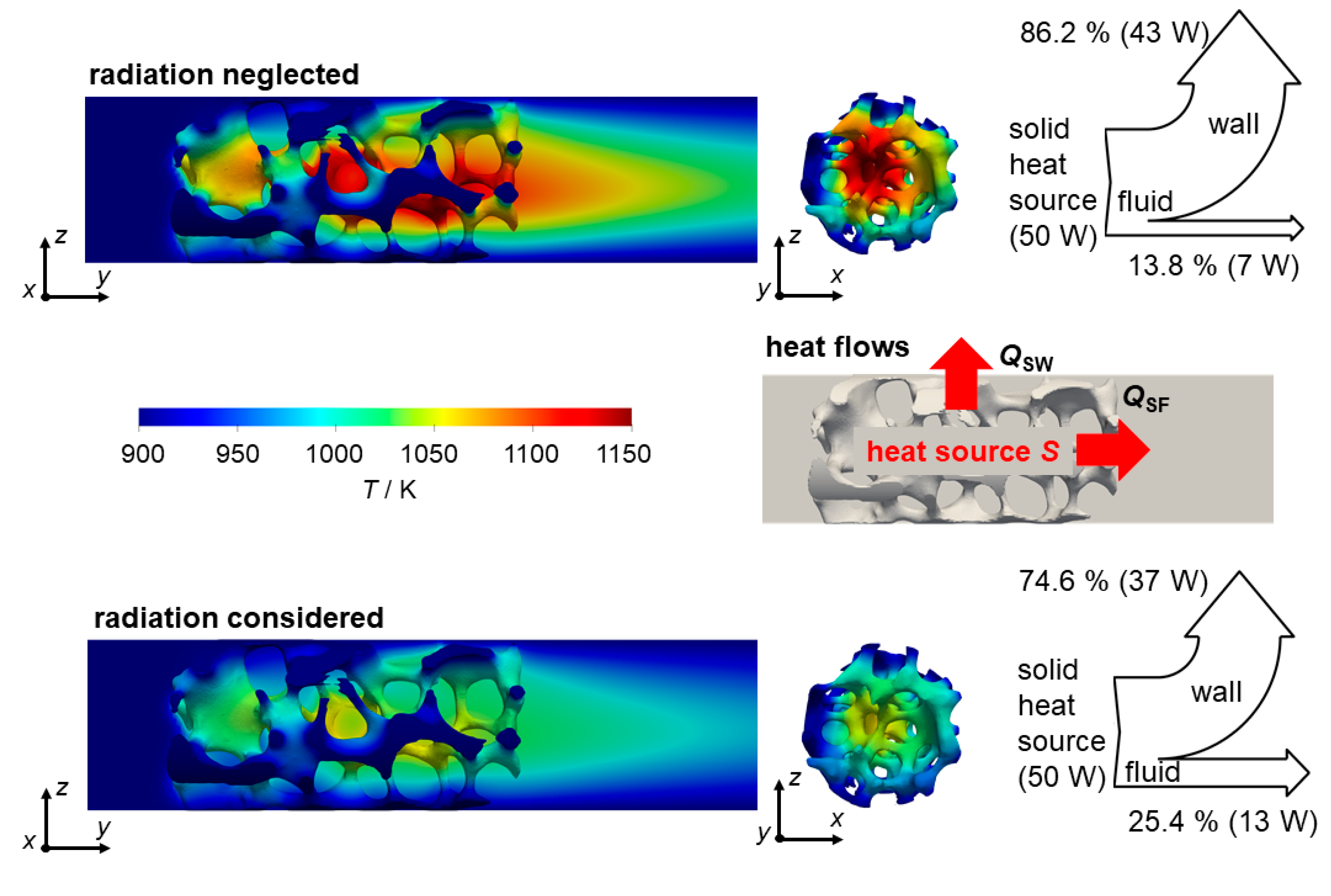
In a second step, the open source OpenFOAM model was verified against the commercial STAR-CCM+ model (see Figure 2). All fluid parameters, except for the emissivity κ, are temperature-dependent and corrected in both models. In contrast, the solid properties are fixed. Resulting heat flows for both models are depicted in Figure 2a,b. All fixed temperature boundary conditions have the same value, which means the only energy entering the system is caused by the volumetric homogeneously distributed heat source in the solid (see Figure 3).
Therefore, the simple global energy balance for the system reads:
where QSF denotes the heat flow transferred from the solid to the fluid and QSW denotes the conductive heat flow from the solid to the wall. The bar graphs in Figure 2a,b, thus all individually sum up to 50 W. For a wall temperature of Tw = 900 K (a) and without considering radiation, the convective part of the stacked bar (blue: solid/fluid) is less than 20% of the overall heat flow for both, the OpenFOAM as well as the STAR-CCM+ model. When radiation is accounted for, this ratio becomes larger than 20%. The consideration of radiation in the conjugate heat transfer model enables another heat transport path for the thermal energy. Hence, the solid temperature distribution becomes more homogeneous (see Figure 3). Here, the heat flow from solid to wall is purely conductive whereas computed heat flow from solid to fluid combines convective as well as radiative heat transfer. Consequently, the computed heat flow from solid to fluid increases. This is because the more homogeneous solid temperature causes a larger (i.e., distributed over a larger foam part) temperature gradient between solid and fluid at the parts of the foam that were cooler when radiation was neglected. For a wall temperature of Tw = 1200 K (b), the same behavior can be observed. In general, the calculated heat flows from OpenFOAM and STAR-CCM+ are comparable for both temperature levels and with or without radiation, indicating the applicability of either software.
The extra heat transport pathway due to radiation significantly influences the temperature distribution. A flattening of maximum and mean solid temperatures can be observed upon consideration of radiation for both temperatures (see Figure 2c,d). Comparing the maximum and median temperature with and without radiation between OpenFOAM and STAR-CCM+, the differences between both software packages are more pronounced compared to the heat flows, especially when looking at the maximum solid temperature calculated from both software packages. This deviation is, however, still insignificant, with a maximum discrepancy of less than 15 K at most. The temperature histograms (Figure 4a,b) show a qualitatively comparable distribution of the temperature increases per volume fraction regardless if radiation is considered or not. However, deviations between both software packages are identifiable especially for the last bins of Figure 4a,b. It can therefore be concluded that the alternating applied discretization methods (e.g., cell morphology) could be the reason for the slight deviations. The negligible deviations between both software packages indicates the applicability of either tool. The detailed solid and fluid temperature distribution of all cases are not shown in the following, since for the very same foam we already analyzed temperature fields of both phases for several applied heat source intensities, superficial velocities, and thermal conductivities systematically [28]. We concluded that the entire solid and fluid temperature fields shift similarly and hence show same trends. In the following, we also omit showing both heat flows, i.e., solid/fluid and solid/wall, since the missing can easily be calculated using Equation (2).
2.2. Quantification of Heat Flows and Temperature Distributions
2.2.1. Influence of the Wall Temperature and Solid Thermal Conductivity
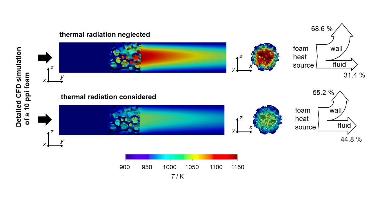
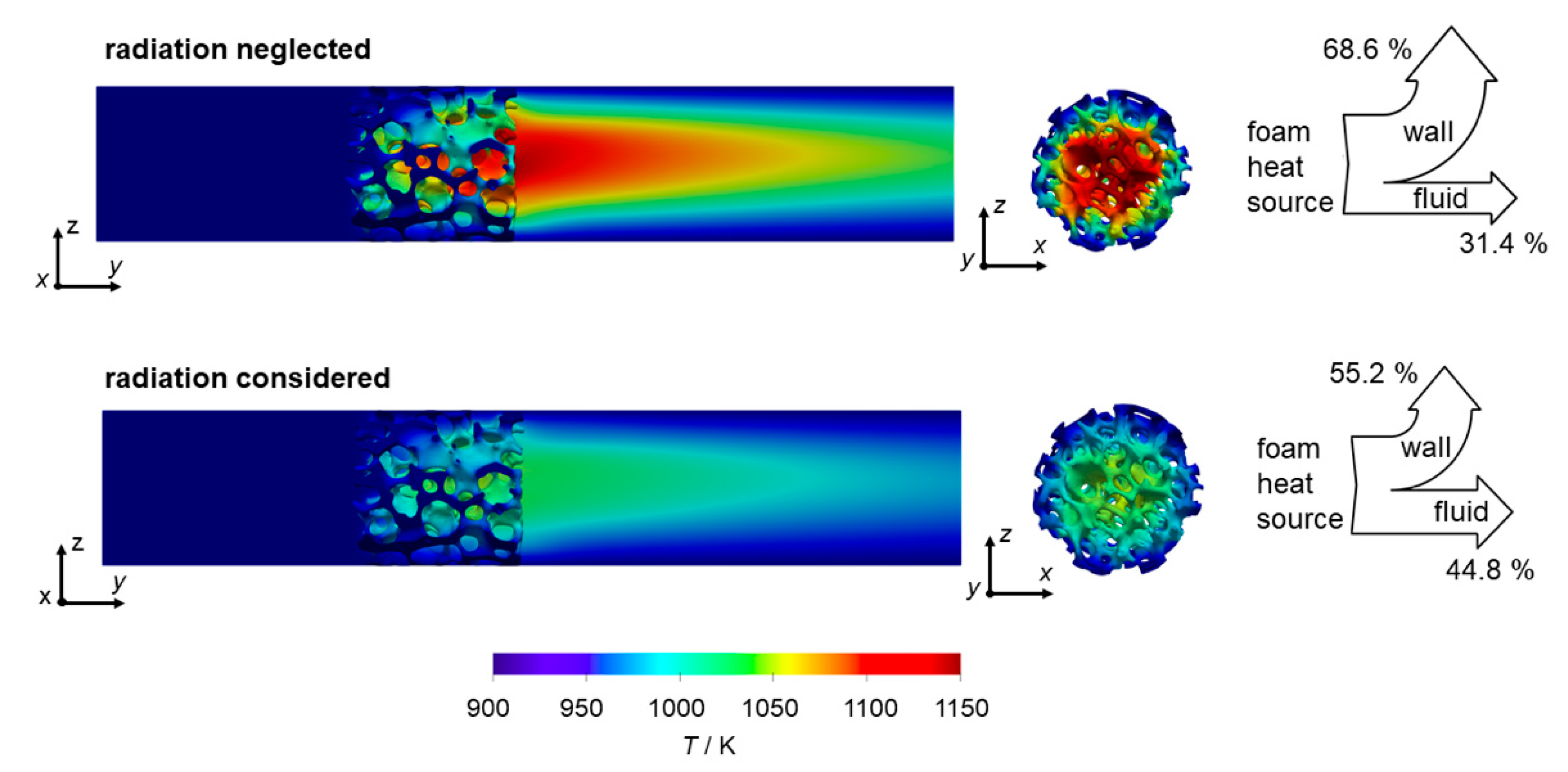
Figure 5 shows fluid temperature in the center plane for a case with and without radiation (Tw = 900; λs =5 W m−1 K−1). Here, the fluid temperature drastically increases when radiation in the model is neglected. Furthermore, the overall increased fluid temperature also enhances the development of the temperature wake behind the foam. Consequently, the solid foam temperature increases when radiation is neglected (Figure 5). Keep in mind that a constant heat source (50 W) is set in the solid volume. A perfect wall contact between foam and wall ensures unhindered heat transport [42], which results in a relatively cool outer zone of the foam. In contrast, inside the solid, hot spots develop which strongly depend on the thermal conductivity [28]. The drastic changes in both fluid and solid temperatures, due to radiation effects, can cause dramatically different results when an actual catalytic chemical reaction is simulated. This is especially true when the overall conversion is mainly influenced by the temperature (i.e., kinetically controlled regime). The homogeneously distributed heat source approach cannot determine the actual maximum temperature of a chemical reaction, because the heat production varies locally due to temperature-dependent kinetics. Nevertheless, the maximum temperature increase, calculated by the heat source approach, can at least be expected in an actual exothermal reaction when the same amount of heat is released.
The fact that neglecting thermal radiation effects in fixed-bed reactors can cause significantly different simulated temperature distributions was already reported [35,36]. These results were obtained for a specific reaction and pellets used as catalyst carriers. With the aid of heat sources, as shown here, the thermal effects can be described decoupled from specific chemistry or reaction and are thus more universal. To assess the deviation caused by neglecting radiation in heterogeneous catalysis, we conduct a systematic parameter variation and quantify the influence of radiation modeling on temperature profiles and heat flows. Firstly, we investigate the influence of the applied temperature level on the heat flows (Figure 6). Since the absolute temperature level affects the radiative heat flow by the power of 4 (see Equation (8)), the absolute deviation between cases with and without considered radiation increases distinctively with temperature (as we will see). For the cases depicted in Figure 5 (Tw = 900 K and λs = 5 W m−1 K−1), the absolute deviation amounts to almost 7 W (14%). Furthermore, we observe that, from a threshold on (λs = 5 W m−1 K−1), the absolute deviations in radiative heat flow decrease with increasing solid thermal conductivities. This is due to the less pronounced heat transport limitations in the foam center for high conducting materials. Here, heat is more likely transported via conduction through the continuous solid strut network and thus, the two models yield more comparable results. Even for quite high solid thermal conductivities the absolute deviations in radiative heat flow can be substantial. For instance, for λs = 50 W m−1 K−1 at Tw = 1200 K the absolute deviation amounts to 8 W (16%) and for λs =200 W m−1 K−1 still to approx. 4 W (8%), respectively. That means even for highly conducting materials (e.g., metals) radiation in open-cell foams cannot generally be neglected at low flowrates.
Interestingly, the absolute deviation in heat flows is not monotonically decreasing with λs, but the values for very low thermal conductivities, i.e., λs = 1 W m−1 K−1, are all lower than for intermediate values. Here, the absolute deviation caused in radiative heat flow can be almost 50% lower than at λs = 5 W m−1 K−1 (which is the second data point, compare for instance purple line in Figure 6). The reason for that diverging behavior certainly lies in the drastic temperature increase of both phases (fluid and solid) at very low solid thermal conductivity. The corresponding maximum and mean deviations in temperature increases support this hypothesis (Figure 7). Between the two smallest investigated solid thermal conductivities, i.e., when λs is increased from 1 W m−1 K−1 to 5 W m−1 K−1, the deviations in maximum and mean temperatures decrease tremendously. As a consequence, for the given boundary conditions, the impact of radiation modeling on heat flows is negligible at very low λs as the entire system itself (fluid and solid temperatures) forms a temperature hot spot. Here, the relative difference between the phase temperatures decrease and hence the absolute deviation of the heat flows.
The absolute deviations in radiative heat flows and in maximum and mean temperature increase show a similar general trend. Hence, increasing thermal conductivities generally decreases the deviation caused when radiation is not considered. However, the absolute deviations of radiative heat flows might significantly differ from the temperature deviation when compared at the same certain condition. As an example, for a solid thermal conductivity of λs = 50 W m−1 K−1, the absolute deviation for both maximum and mean temperature increase are negligible regardless of the applied temperature level (Figure 7a,b). In contrast, the absolute deviations in heat flows can still be as high as 8 W (of 50 W total heat flow). Even at λs = 200 W m−1 K−1, there is a 4 W (i.e., almost 10%) deviation in radiative heat flow at 1200 K wall temperature while deviations in mean and maximum temperature increase are virtually non-existent. This indicates that the ability of the foam to transport heat via conduction (i.e., the thermal conductivity) is not limiting and can balance the missing contribution of the radiation. Concluding, even though no temperature changes can be identified between models with and without radiation, the absolute and relative deviation in computing the heat flows can still be significant. Hence, one should consider these findings before omitting radiation modeling in open-cell foams at elevated temperatures. Once again, we want to stress that, for actual chemical reactions, the absolute deviations for maximum temperatures between models with and without radiation should be even more severe (when equal amounts of heat production are compared).
2.2.2. Influence of the Superficial Velocity
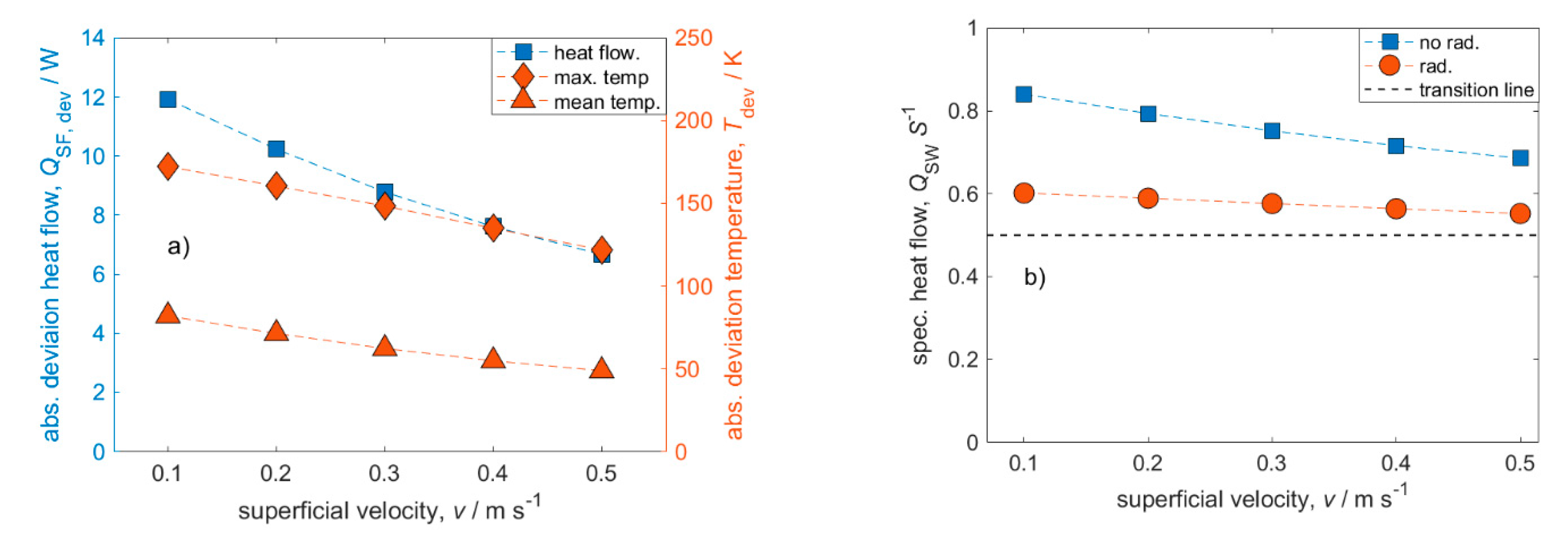
Catalytic foam reactors can outperform conventional pellet fixed-bed reactors at low velocities [5]. Therefore, the influence of radiation modeling on heat flows as well as temperature increases at different superficial velocities was also quantified. For a wall temperature of Tw = 900 K and a solid thermal conductivity of λs = 5 W m−1 K−1, the corresponding absolute deviations in heat flow as well as deviations in maximum and mean temperature are plotted against the superficial velocity in Figure 8a. Both the absolute deviation for heat flows and temperatures decrease with increasing superficial velocity. In the investigated range of superficial velocities, the absolute error for heat flows increases from about 7 W (14%, for 0.5 m s−1) to about 12 W (24%, for v = 0.1 m s−1). Due to increasing convective heat transfer between the fluid and solid at higher superficial velocities, the foam is cooled more efficiently. Therefore, the contribution of radiation as heat transport mechanism obviously decreases with increasing superficial velocity, as convection becomes more dominant. This is underlined by the specific heat flow from solid to wall plotted against the superficial velocity (Figure 8b). The transition line indicates the dominant heat removal mechanism. A value greater than 0.5 means conduction is dominant whereas a value lower than 0.5 mean convection is dominant. Here, all simulations are conduction dominated, although the case with highest investigated velocity (0.5 m s−1) and considered radiation becomes close to convection dominated. Concluding, for foam reactors with conditions where convection is dominant, the consideration of radiation is definitely less important. Here, it can only be assumed that the absolute error, which can reach values up to 24% (Figure 6), would have an asymptotic behavior for even higher superficial velocities. This should be addressed in further studies. We would like to note that the results from Figure 6 and Figure 7 would have shown even larger absolute deviations at smaller superficial velocities. Hence, the magnitude of superficial velocities plays a major role in the consideration of radiation.
2.2.3. Comparison with a Homogeneous Model
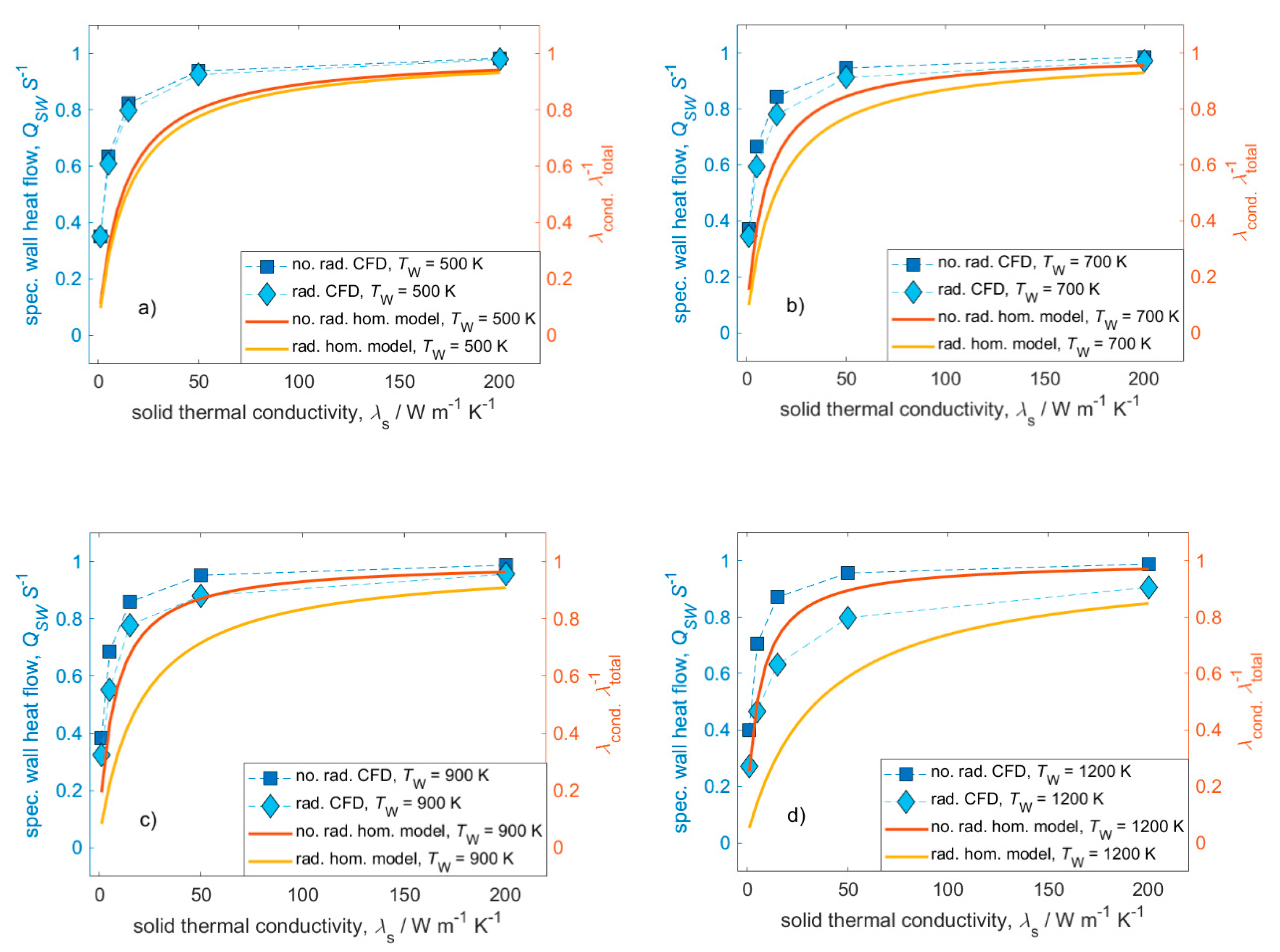
This work’s CFD simulations already highlighted and quantified the importance of radiation modeling under certain process conditions (e.g., temperature level and solid thermal conductivity). To assess if the modeling and simulation effort of CFD simulations for the presented cases is justified, a comparison between CFD simulation results and analytical results calculated using a simple pseudo-homogeneous model is conducted in the following. Pseudo-homogeneous models consider only one effective phase and, thus, have an average temperature and an effective (or two-phase) thermal conductivity. For homogeneous models this effective thermal conductivity is the key transport property, which can be obtained through experiments or heterogeneous models. Since homogeneous models only consider one phase, there is technically no heat transfer, only effective heat transport. Currently, there are only two pseudo-homogeneous models available that consider thermal radiation and forced convection [21,26]. The parameter range from Fischedick et al. [26] is more suitable for this study and is consequently used in this study. The radial contribution to the effective thermal conductivity resembles approximately with the heat flow from solid to wall and further consists of a stagnant part (conduction + radiation) and a dispersive part (convection):
The ratio of conductive effective thermal conductivity to total effective thermal conductivity should give the same trend as the specific heat flow solid to wall (QSW S−1). This approximation should be valid as long as temperature differences remain low between the cases (i.e., high thermal solid conductivities). The heat flow ratios and ratios of the effective thermal conductivities, respectively, are plotted against the full range of thermal conductivities at different temperature levels in Figure 9. Both approaches show the same qualitative trend regardless of the consideration of radiation or the applied temperature level. The homogeneous model reflects the trends of decreasing importance of radiation modeling for increasing thermal conductivities as well as decreasing temperature levels. It can also be seen that the simulation results as well as the analytical model agree better at high thermal conductivity and low temperature level. With increasing temperature levels, the contribution of radiation in the analytical model seems to be more pronounced than in the CFD simulations. When compared to experimental data, the homogeneous model was able to match approximately 80% of the data points with less than 30% deviation [26]. Hence, the homogeneous model can give a convenient fast glance on the general contribution of radiation on the total heat transport. However, for a more thorough quantification, CFD simulations or experiments are needed. Further, the need for even more accurate (engineering) models that can be used for the estimation of heat transport contributions becomes obvious.
2.2.4. Influence of the Surface Emissivity
So far, the surface (or solid) emissivity has been set to a fixed value of ε = 0.9 in all simulations. This value depends on surface texture, material, wavelengths, absorbed molecules, and other parameters [43]. In practice, the exact determination of the surface emissivity might be challenging. For catalytic reactions, the foams are generally coated with active catalytic material (i.e., washcoat). The washcoats might change and differ in their surface emissivity. On top of that, the surface emissivity might change during chemical reactions due to soot or coke deposition. Therefore, it is often only practical to estimate a range of surface emissivities.
Generally, the surface emissivity describes the participation of the solid phase in radiative heat transport. Hence, with decreasing surface emissivity, the radiative heat flow drops while the solid temperature rises (Figure 10). A low surface emissivity thus indicates little solid contribution to the radiation. However, when ε larger than 0.5 and at wall temperatures of Tw = 900 K and Tw = 700 K, heat flows and solid temperature (mean and maximum) are almost independent of ε. For the elevated wall temperature, Tw = 1200 K, changes in heat flows and solid temperatures are more pronounced and heat flows and temperatures become independent of ε only for ε almost 1. Concluding, increased wall temperatures also increase the influence of ε on heat flows and temperature fields. In the surface emissivity range 0 < ε < 0.5, the changes in heat flows and temperatures are more severe. Hence, inaccurately determined emissivity values influence simulation results more significantly for materials with general lower emissivity.
3. Materials and Methods
3.1. General Model and Meshing
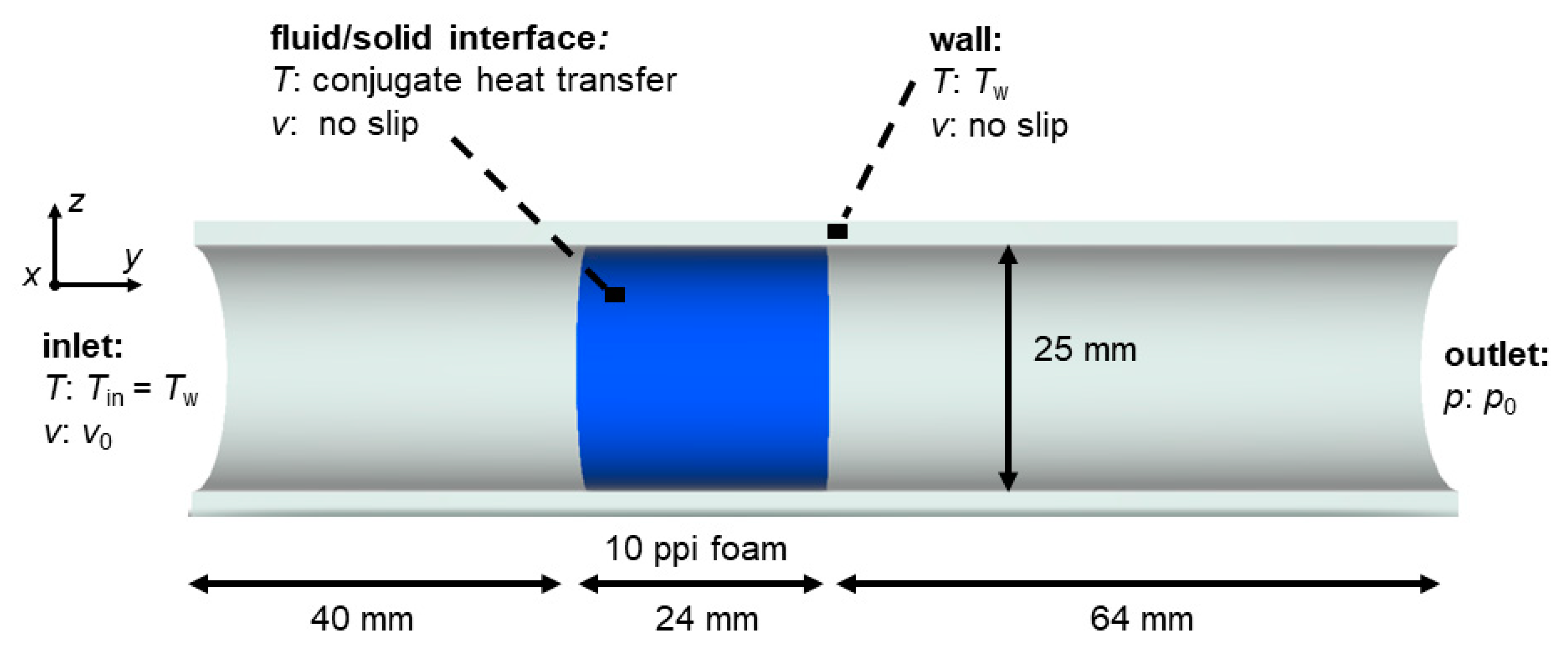
The investigated geometry represents a structured reactor, consisting of a 10 ppi alumina µCT-based foam embedded in a tube (see Figure 11). In front and behind the embedded foam are a 40 mm inlet and a 64 mm outlet section, respectively. The overall processing (from scanning to actual CAD model) of the 10 ppi µCT foam is described in more detail in [28]. Furthermore, the geometrical properties of the foam can be found in Appendix A (Table A1). The model of this study addresses the laminar steady-state conjugate heat transfer between air and foam with the explicit consideration of radiation. The same fixed temperature boundary conditions are prescribed at the wall as well as the fluid inlet. The solid phase contains a homogeneously distributed heat source which is the only energy that enters the system. The fixed value of S = 50 W was determined in a previous study to be the representative thermal power that evolves during the CO2 methanation reaction in a foam [6,28], which was adopted for this study. We note that, the effect of heat source can be easily extrapolated to other heat source intensities as it was shown in [28] for the range of 5 ≤ S ≤ 150 W.
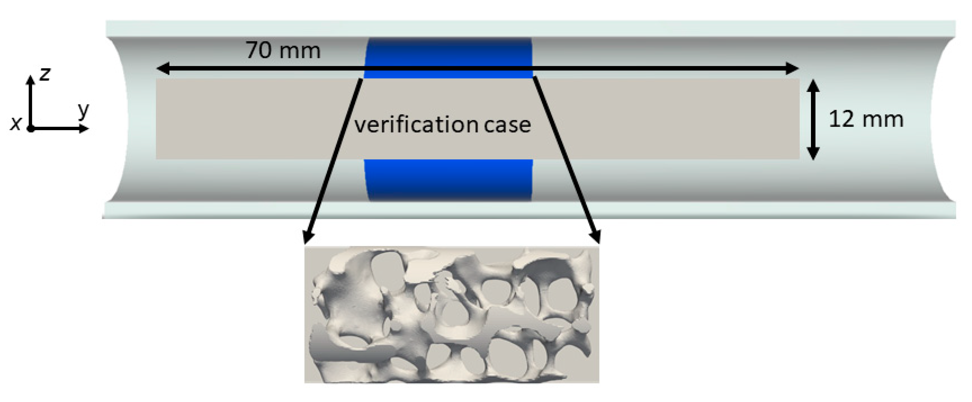
Most of the results of this work were gained using the open source finite-volume-based toolbox OpenFOAM (version 7, [44]) and the solver chtMultiRegionFoam. For the OpenFOAM multi-region meshes, the cartesian mesh creator snappyHexMesh was utilized. For the verification against the commercial CFD software STAR-CCM+ from Siemens PLM (Plano, TX, USA) [45], a polyhedral mesh was created with the integrated STAR-CCM+ meshing utility. To speed up meshing and simulations, only a representative part of the foam (Ø12 × 24 mm, see Appendix B, Figure A1) was used for comparison and verification.
3.2. Governing Equations and Thermal Radiation Modeling
Aside from the radiation modeling, the major parts of this work’s model are similar to our previous study [28]. The essential model properties are listed in Table 1. For additional information regarding the model, the reader is thus referred to [28].
For the Newtonian fluid (air) with neglected gravitation, the conservation equations for mass reads:
with ρf denoting the fluid’s density and U denoting the velocity field. The conservation of momentum can be described by:
where h denotes the enthalpy, which is followed by the conservation of energy:
with λf being the fluid’s thermal conductivity. The solid phase, in contrast, is described only by the conservation of energy:
with λs being the solid’s thermal conductivity, Ts the solid’s temperature, and S the specific artificial heat source. The set of equations is completed by the ideal gas law.
At high temperatures the effect of thermal radiation on the overall heat transport might be severe. In contrast to conduction and convection, radiation does not need media to transport heat since electromagnetic waves can spread in vacuum. Further, heat transport by radiation does not only depend on the value of the temperature gradient, but also on the absolute temperature level. The maximum specific heat flow (W m−2), that a real solid body emits, can be expressed by the Stefan–Boltzman law (Equation (1)) extended by the surface emissivity ε:
with σ being the Stefan-Boltzmann constant (; the surface emissivity is generally between 0 and 1 (colored or real body: ε = f(T); grey body: ε = const.; black body: ε = 1). When radiation hits a material, the energy can be reflected, absorbed or transmitted (depending on e.g., wavelength or material):
with γ denoting the degree of reflection, α the degree of absorption and τ the degree of transmission.
Furthermore, the radiant intensity I is the specific radiant heat flux per unit solid angle (W m−2 sr−1):
Generally, radiation modeling in CFD codes can be distinguished in approaches with and without fluid participation. OpenFOAM contains the three radiation models viewFactor (no fluid participation), fvDOM (finite volume discrete ordinate model), and the P1 model. In a preliminary study we found that an inappropriate model can severely overestimate the contribution of radiation to the overall heat transport (relative error Erel = 50%; Appendix C). In this study, only fluid participating approaches are used as they have been successfully applied in literature for high temperature heat transfer and are also suitable for symmetry boundary conditions [34,35,47]. We also note that the fluid participation should not play a significant role in this study for the model fluid (air) as well as the model conditions (i.e., atmospheric pressure, temperatures and geometrical dimensions) [34,35]. Both models basically solve the radiative transfer equation (RTE) that describes the change of the radiant intensity at any point along a path through a participating medium (fluid) depending on scattering, emission and adsorption effects [43]. For further explanation and discussion the reader is referred to [43] and [48]. The RTE reads [34,48]:
where r denotes the position vector, s the direction vector, κ the fluid’s absorption coefficient and Ib denotes the black body intensity, σs the scattering coefficient, Iincident the incident intensity, Φ(si,s) the scattering phase function and Ωi the solid angle.
The calculated radiative heat flows are eventually included in the energy conservation source term. In this study, only the fvDOM (OpenFOAM) and DOM (STAR-CCM+ for verification) models are used. The choice of the fvDOM model over the P1 model is justified in Appendix C. The P1 radiation model (or P-1 model) is the simplest approximation of P-N models. It is based on the expansion of the RTE into an orthogonal series of spherical harmonics [49]. The P1 model is particularly useful for accounting for the radiative exchange between gas and particles [49]. In contrast, the fvDOM as well as the DOM model solve the RTE for a finite number of solid angles Ω with an associated vector direction s [43]. The full solid angle of 4π is divided into discrete angular parts of the sphere. The number of divisions is a trade-off between accuracy and computational cost as it determines the number of rays and hence the size of the equation system that need to be solved. For all OpenFOAM simulations we found the azimuthal angle Φ = 3 and the polar angle Θ = 4 to be sufficient, whereas for all STAR-CCM+ simulations we found the number of ordinates equal 4 (S4) as satisfactory.
Due to the lack of (soot) particles as well as relatively low distances, no scattering model is needed for this study [34]. For a non-scattering medium, the RTE reads:
Moreover, a radiation boundary condition that applies for all solid walls needs to be set up. For an opaque, grey and diffusely emitting wall with the position vector rw, the initial intensity from all possible directions si reads [48]:
with n being the unit normal vector. All other main boundary conditions are depicted in Figure 11.
4. Conclusions
In this study, the contribution of thermal radiation modeling of a foam reactor was quantified with respect to several key parameters in heterogeneous catalysis. Firstly, the choice of a suitable radiation model is very important when investigating the heat transport behavior of open-cell foams. An inappropriate model can severely overestimate the contribution of radiation to the overall heat transport (relative error Erel = 50%). Secondly, an influence of radiation on the simulated heat flows and temperature increases was found for the following parameters in decreasing order: 1. overall temperature level (here, wall temperature Tw and inlet temperature Tin), 2. solid thermal conductivity, 3. superficial velocity, and 4. surface emissivity. At four temperature levels corresponding with a range of industrially-relevant chemical reactions in heterogeneous catalysis (500 K: Fischer–Tropsch synthesis; 700 K: CO2 methanation; 900 K: dry reforming of methane; 1200 K: methane steam reforming), the influence of radiation modeling was quantified. At most, we found maximum temperature deviations of up to 400 K and a discrepancy in heat flows of about 12 W (24%).
Even though highly conductive materials (e.g., metals) do not show significant deviations in temperature increases when radiation is neglected, their heat flow ratio (transferred from solid to fluid or transport from solid to wall) still might change distinctively. Hence, temperature increases cannot be the only measure to justify the neglect of radiation. Furthermore, during actual reactions, ignoring radiation can lead to a wrong interpretation as thermal effects might be attributed to reaction kinetics. Once again, we want to highlight that temperature deviations for negligence of radiation in actual chemical reactions might be more significant due to locally varying, temperature-dependent heat production. Prospectively, the influence of geometry also needs to be further addressed as this study only focused on an individual foam sample. Such study should target a range of irregular foams as well as regular structures (e.g., Kelvin cells), in order to more accurately quantify the influence of radiation in reactor modeling. Equivalently, the current parameter range could be extended to quantify radiation at higher velocities and coupled turbulence modeling as well as quantify the effect of different participating fluids (e.g., CO2) with potential scattering. The heat source approach further underlined its suitability to effectively study thermal effects of catalyst carriers decoupled from chemistry. A deeper understanding of heat transport processes in foams in particular and structured reactors in general can lead to more accurate foam reactor models and consequently to intensified processes. This knowledge might help to facilitate the launch of structured reactors into industrial application.
Author Contributions
Conceptualization: C.S., F.K., J.W., G.R.P., and J.T.; methodology: C.S., F.K., J.W., and G.D.W.; software: F.K. and C.S.; writing—original draft preparation: C.S.; writing—review and editing: G.R.P., G.D.W., and J.T.; visualization: C.S.; supervision: G.R.P. All authors have read and agreed to the published version of the manuscript.
Funding
Christoph Sinn and Jorg Thöming thank the German Research Foundation (DFG) for funding by the priority program SPP 2080 (Katalysatoren und Reaktoren unter dynamischen Betriebsbedingungen für die Energiespeicherung und -wandlung) under grant TH 893/23-1.
Conflicts of Interest
The authors declare no conflict of interest.
Appendix A. Geometrical Foam Properties

Table A1.
Properties of the 10 ppi alumina foam used in this study.
| Parameter | Symbol | Value |
|---|---|---|
| pore count | 10 ppi | |
| open porosity | ε0 | 0.77 |
| specific surface area | SV | 521.3 m−1 |
| cell diameter | dc | 5.76 ± 1.9 mm |
| window diameter | dw | 3.3 ± 0.9 mm |
| strut diameter | ds | 1.5 ± 0.5 mm |
Appendix B. Geometry for Verification
Figure A1.
Illustration of foam clip used for the verification study.

Appendix C. Analysis of P1 and fvDOM Radiation Models for Suitability in Open-Cell Foams
Figure A2.
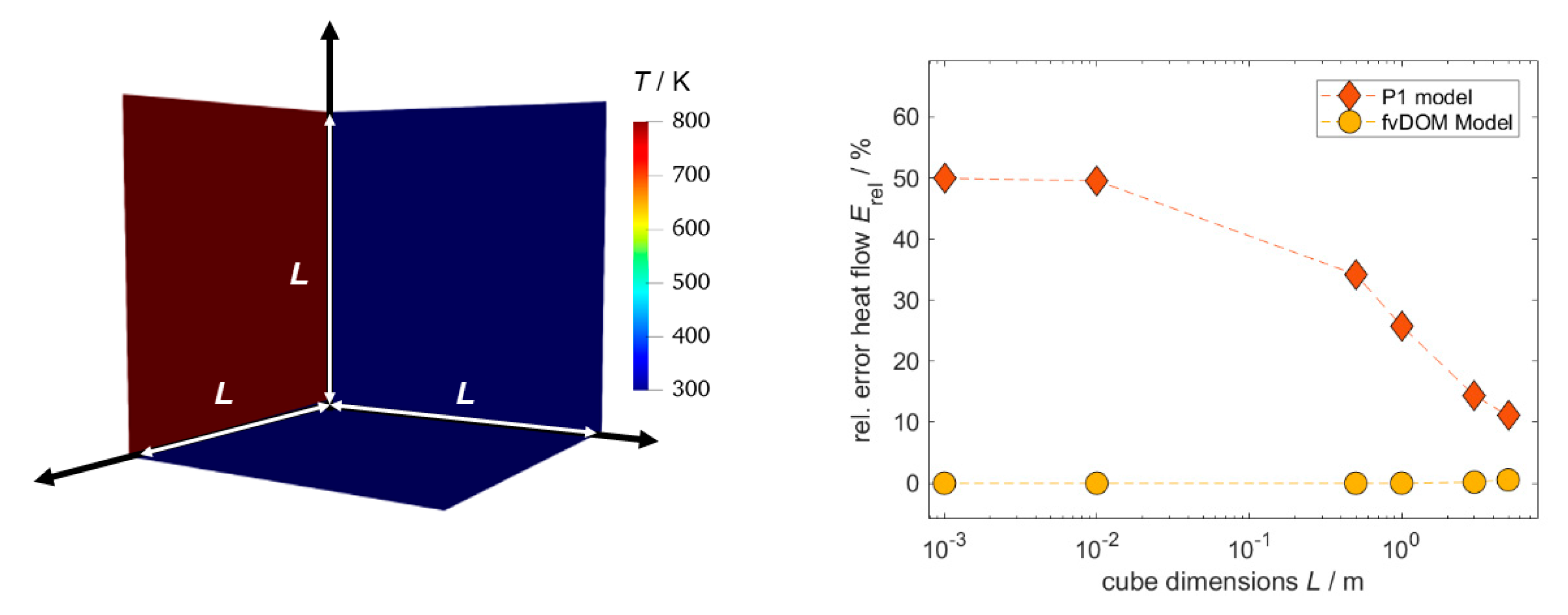
Test for suitability of P1 and fvDOM models used for radiation modeling in open-cell foams. Left: illustration of case (geometry = cube) and temperature boundary condition. Right: relative error of radiative heat flow between numerical solution and analytical solution plotted against cube dimensions.
Figure A2.
Test for suitability of P1 and fvDOM models used for radiation modeling in open-cell foams. Left: illustration of case (geometry = cube) and temperature boundary condition. Right: relative error of radiative heat flow between numerical solution and analytical solution plotted against cube dimensions.

In order to check which fluid participating radiation model in OpenFOAM is suitable for utilizing in heat transport simulations in open-cell foams, a simple test case was set up (Figure A2). The test case is a cube with flexible dimensions and fixed temperature boundary conditions of 300 K at five sides and one side with 800 K. Vacuum is assumed inside the cubes, which makes radiation the principal heat transport mechanism. The resulting steady-state specific radiative heat flux can easily be calculated analytically (for a ε = 1) as:
We also set up simulation cases that solved for the very same specific heat flux with both, fvDOM and P1 model, for various cube dimensions (solver buoyantSimpleFoam). We note that all meshes (single region) were created with the blockMesh utility of OpenFOAM and tested for grid independence. The relative error between analytical and numerical solution plotted against the cube dimensions for both models is also shown in Figure A2. A significant deviation between P1 model and analytical solution (>20%) can be observed for small cube dimensions, while for increasing cube dimensions the error shrinks. In contrast, the fvDOM model shows almost no deviation to the analytical model for all cube dimensions. For the fixed number of solid angles, the error slightly increases for dimensions larger than 3 m. This behavior might change when more solid angles and thus more equations are solved. At the small distances relevant for this study, the error due to the P1 model is almost 50% which is not acceptable for appropriate results. Thus, only the fvDOM model is used for quantification in this work.
List of Symbols
| Latin | |
| cp | Isobaric heat capacity, J Kg−1 K−1 |
| dc | Cell diameter, m |
| ds | Strut diameter, m |
| dw | Window diameter, m |
| Erel | Relative error of heat flow, - |
| I | Intensity, W m−2 sr−1 |
| L | Cube dimensions, m |
| Q | Heat flow, W |
| QSF | Heat flow solid to fluid, W |
| QSW | Heat flow solid to wall, W |
| h | Specific enthalpy, J |
| p | Pressure, Pa |
| r | Position vector, - |
| s | Direction vector, - |
| S | Total heat source intensity, W |
| Sv | Specific surface area, m−1 |
| T | Temperature, K |
| Tw | Wall temperature, K |
| Tmax | Maximum temperature, K |
| Tmean | Mean temperature, K |
| U | Velocity, m s−1 |
| v | Superficial velocity, m s−1 |
| Greek | |
| α | Degree of absorption, - |
| γ | Degree of reflection, - |
| τ | Degree of transmission, - |
| Ω | Solid angle, sr |
| κ | Absorption coefficient, m−1 |
| σs | Scattering coefficient, m−1 |
| ε0 | Open porosity, - |
| ε | Surface emissivity, - |
| μ | Dynamic viscosity, Pa s |
| λ | Thermal conductivity, W m−1 K−1 |
References
- Kiewidt, L.; Thöming, J. Predicting optimal temperature profiles in single-stage fixed-bed reactors for CO2-methanation. Chem. Eng. Sci. 2015, 132, 59–71. [Google Scholar] [CrossRef]
- Rönsch, S.; Schneider, J.; Matthischke, S.; Schluter, M.; Götz, M.; Lefebvre, J.; Prabhakaran, P.; Bajohr, S. Review on methanation—From fundamentals to current projects. Fuel 2016, 166, 276–296. [Google Scholar] [CrossRef]
- Kalz, K.F.; Kraehnert, R.; Dvoyashkin, M.; Dittmeyer, R.; Gläser, R.; Krewer, U.; Reuter, K.; Grunwaldt, J.-D. Future Challenges in Heterogeneous Catalysis: Understanding Catalysts under Dynamic Reaction Conditions. ChemCatChem 2016, 9, 17–29. [Google Scholar] [CrossRef] [Green Version]
- Solomon, A.; Kammen, D.M.; Callaway, D. The role of large-scale energy storage design and dispatch in the power grid: A study of very high grid penetration of variable renewable resources. Appl. Energy 2014, 134, 75–89. [Google Scholar] [CrossRef]
- Kiewidt, L.; Thöming, J. Pareto-optimal design and assessment of monolithic sponges as catalyst carriers for exothermic reactions. Chem. Eng. J. 2019, 359, 496–504. [Google Scholar] [CrossRef]
- Kiewidt, L.; Thöming, J. Multiscale modeling of monolithic sponges as catalyst carrier for the methanation of carbon dioxide. Chem. Eng. Sci. X 2019, 2, 100016. [Google Scholar] [CrossRef]
- Graf, I.; Rühl, A.-K.; Kraushaar-Czarnetzki, B. Experimental study of heat transport in catalytic sponge packings by monitoring spatial temperature profiles in a cooled-wall reactor. Chem. Eng. J. 2014, 244, 234–242. [Google Scholar] [CrossRef]
- Reitzmann, A.; Patcas, F.C.; Kraushaar-Czarnetzki, B. Keramische Schwämme—Anwendungspotenzial monolithischer Netzstrukturen als katalytische Packungen. Chem. Ing. Tech. 2006, 78, 885–898. [Google Scholar] [CrossRef] [Green Version]
- Meinicke, S.; Dubil, K.; Wetzel, T.; Dietrich, B. Characterization of heat transfer in consolidated, highly porous media using a hybrid-scale CFD approach. Int. J. Heat Mass Transf. 2020, 149, 119201. [Google Scholar] [CrossRef]
- Bianchi, E.; Heidig, T.; Visconti, C.G.; Groppi, G.; Freund, H.; Tronconi, E. Heat transfer properties of metal foam supports for structured catalysts: Wall heat transfer coefficient. Catal. Today 2013, 216, 121–134. [Google Scholar] [CrossRef]
- Razza, S.; Heidig, T.; Bianchi, E.; Groppi, G.; Schwieger, W.; Tronconi, E.; Freund, H. Heat transfer performance of structured catalytic reactors packed with metal foam supports: Influence of wall coupling. Catal. Today 2016, 273, 187–195. [Google Scholar] [CrossRef]
- Della Torre, A.; Montenegro, G.; Tabor, G.R.; Wears, M. CFD characterization of flow regimes inside open cell foam substrates. Int. J. Heat Fluid Flow 2014, 50, 72–82. [Google Scholar] [CrossRef] [Green Version]
- Regulski, W.; Szumbarski, J.; Łaniewski-Wołłk, Ł.; Gumowski, K.; Skibinski, J.; Wichrowski, M.; Wejrzanowski, T. Pressure drop in flow across ceramic foams—A numerical and experimental study. Chem. Eng. Sci. 2015, 137, 320–337. [Google Scholar] [CrossRef]
- Bracconi, M.; Ambrosetti, M.; Maestri, M.; Groppi, G.; Tronconi, E. A fundamental analysis of the influence of the geometrical properties on the effective thermal conductivity of open-cell foams. Chem. Eng. Process. Process. Intensif. 2018, 129, 181–189. [Google Scholar] [CrossRef]
- Diani, A.; Bodla, K.K.; Rossetto, L.; Garimella, S.V. Numerical investigation of pressure drop and heat transfer through reconstructed metal foams and comparison against experiments. Int. J. Heat Mass Transf. 2015, 88, 508–515. [Google Scholar] [CrossRef] [Green Version]
- Zafari, M.; Panjepour, M.; Emami, M.D.; Meratian, M. Microtomography-based numerical simulation of fluid flow and heat transfer in open cell metal foams. Appl. Therm. Eng. 2015, 80, 347–354. [Google Scholar] [CrossRef]
- Bianchi, E.; Schwieger, W.; Freund, H. Assessment of Periodic Open Cellular Structures for Enhanced Heat Conduction in Catalytic Fixed-Bed Reactors. Adv. Eng. Mater. 2015, 18, 608–614. [Google Scholar] [CrossRef]
- Iasiello, M.; Cunsolo, S.; Bianco, N.; Chiu, W.; Naso, V. Developing thermal flow in open-cell foams. Int. J. Therm. Sci. 2017, 111, 129–137. [Google Scholar] [CrossRef]
- Nie, Z.; Lin, Y.; Tong, Q. Numerical investigation of pressure drop and heat transfer through open cell foams with 3D Laguerre-Voronoi model. Int. J. Heat Mass Transf. 2017, 113, 819–839. [Google Scholar] [CrossRef]
- Mendes, M.; Skibina, V.; Talukdar, P.; Wulf, R.; Gross, U.; Trimis, D.; Ray, S. Experimental validation of simplified conduction–radiation models for evaluation of Effective Thermal Conductivity of open-cell metal foams at high temperatures. Int. J. Heat Mass Transf. 2014, 78, 112–120. [Google Scholar] [CrossRef]
- Bianchi, E.; Heidig, T.; Visconti, C.G.; Groppi, G.; Freund, H.; Tronconi, E. An appraisal of the heat transfer properties of metallic open-cell foams for strongly exo-/endo-thermic catalytic processes in tubular reactors. Chem. Eng. J. 2012, 198, 512–528. [Google Scholar] [CrossRef]
- Fischedick, T.; Kind, M.; Dietrich, B. High temperature two-phase thermal conductivity of ceramic sponges with stagnant fluid—Experimental results and correlation including thermal radiation. Int. J. Therm. Sci. 2015, 96, 1–11. [Google Scholar] [CrossRef]
- Dietrich, B.; Fischedick, T.; Heissler, S.; Weidler, P.; Wöll, C.; Kind, M. Optical parameters for characterization of thermal radiation in ceramic sponges—Experimental results and correlation. Int. J. Heat Mass Transf. 2014, 79, 655–665. [Google Scholar] [CrossRef]
- Zhao, C.; Tassou, S.A.; Lu, T. Analytical considerations of thermal radiation in cellular metal foams with open cells. Int. J. Heat Mass Transf. 2008, 51, 929–940. [Google Scholar] [CrossRef]
- Patel, V.M.; Talukdar, P. Evaluation of radiative properties of a representative foam structure using blocked-off region approach integrated with finite volume method. Int. J. Therm. Sci. 2016, 108, 89–99. [Google Scholar] [CrossRef]
- Fischedick, T.; Kind, M.; Dietrich, B. Radial two-phase thermal conductivity of ceramic sponges up to high temperatures—Experimental results and correlation. Int. J. Therm. Sci. 2017, 114, 98–113. [Google Scholar] [CrossRef]
- Dietrich, B.; Schell, K.G.; Bucharsky, E.C.; Oberacker, R.; Hoffmann, M.; Schabel, W.; Kind, M.; Martin, H. Determination of the thermal properties of ceramic sponges. Int. J. Heat Mass Transf. 2010, 53, 198–205. [Google Scholar] [CrossRef]
- Sinn, C.; Pesch, G.R.; Thöming, J.; Kiewidt, L. Coupled conjugate heat transfer and heat production in open-cell ceramic foams investigated using CFD. Int. J. Heat Mass Transf. 2019, 139, 600–612. [Google Scholar] [CrossRef]
- Wu, Z.; Caliot, C.; Flamant, G.; Wang, Z. Numerical simulation of convective heat transfer between air flow and ceramic foams to optimise volumetric solar air receiver performances. Int. J. Heat Mass Transf. 2011, 54, 1527–1537. [Google Scholar] [CrossRef]
- Wehinger, G.D.; Heitmann, H.; Kraume, M. An artificial structure modeler for 3D CFD simulations of catalytic foams. Chem. Eng. J. 2016, 284, 543–556. [Google Scholar] [CrossRef]
- Wehinger, G.D.; Kraume, M.; Berg, V.; Korup, O.; Mette, K.; Schlögl, R.; Behrens, M.; Horn, R. Investigating dry reforming of methane with spatial reactor profiles and particle-resolved CFD simulations. AIChE J. 2016, 62, 4436–4452. [Google Scholar] [CrossRef]
- Dong, Y.; Korup, O.; Gerdts, J.; Cuenya, B.R.; Horn, R. Microtomography-based CFD modeling of a fixed-bed reactor with an open-cell foam monolith and experimental verification by reactor profile measurements. Chem. Eng. J. 2018, 353, 176–188. [Google Scholar] [CrossRef]
- Behnam, M.; Dixon, A.G.; Wright, P.M.; Nijemeisland, M.; Stitt, E.H. Comparison of CFD simulations to experiment under methane steam reforming reacting conditions. Chem. Eng. J. 2012, 207, 690–700. [Google Scholar] [CrossRef]
- Hettel, M.; Daymo, E.; Deutschmann, O. 3D modeling of a CPOX-reformer including detailed chemistry and radiation effects with DUO. Comput. Chem. Eng. 2018, 109, 166–178. [Google Scholar] [CrossRef]
- Wehinger, G.D.; Flaischlen, S. Computational Fluid Dynamics Modeling of Radiation in a Steam Methane Reforming Fixed-Bed Reactor. Ind. Eng. Chem. Res. 2019, 58, 14410–14423. [Google Scholar] [CrossRef]
- Wehinger, G.D. Radiation Matters in Fixed-Bed CFD Simulations. Chem. Ing. Tech. 2019, 91, 583–591. [Google Scholar] [CrossRef]
- Dixon, A.G.; Partopour, B. Computational Fluid Dynamics for Fixed Bed Reactor Design. Annu. Rev. Chem. Biomol. Eng. 2020, 11, 109–130. [Google Scholar] [CrossRef] [Green Version]
- Della Torre, A.; Lucci, F.; Montenegro, G.; Onorati, A.; Eggenschwiler, P.D.; Tronconi, E.; Groppi, G. CFD modeling of catalytic reactions in open-cell foam substrates. Comput. Chem. Eng. 2016, 92, 55–63. [Google Scholar] [CrossRef]
- Güttel, R.; Turek, T. Improvement of Fischer-Tropsch Synthesis through Structuring on Different Scales. Energy Technol. 2015, 4, 44–54. [Google Scholar] [CrossRef]
- Jang, W.-J.; Shim, J.-O.; Kim, H.-M.; Yoo, S.-Y.; Roh, H.-S. A review on dry reforming of methane in aspect of catalytic properties. Catal. Today 2019, 324, 15–26. [Google Scholar] [CrossRef]
- Meloni, E.; Martino, M.; Palma, V. A Short Review on Ni Based Catalysts and Related Engineering Issues for Methane Steam Reforming. Catalysts 2020, 10, 352. [Google Scholar] [CrossRef] [Green Version]
- Bianchi, E.; Groppi, G.; Schwieger, W.; Tronconi, E.; Freund, H. Numerical simulation of heat transfer in the near-wall region of tubular reactors packed with metal open-cell foams. Chem. Eng. J. 2015, 264, 268–279. [Google Scholar] [CrossRef]
- Modest, M.F. Radiative Heat Transfer, 3rd ed.; Academic Press: New York, NY, USA, 2013; Available online: https://0-doi-org.brum.beds.ac.uk/10.1016/C2010-0-65874-3 (accessed on 6 April 2020).
- Weller, H.G.; Tabor, G.; Jasak, H.; Fureby, C. A tensorial approach to computational continuum mechanics using object-oriented techniques. Comput. Phys. 1998, 12, 620. [Google Scholar] [CrossRef]
- STAR-CCM+ (n.d.). Available online: https://www.plm.automation.siemens.com/global/en/products/simcenter/STAR-CCM.html (accessed on 6 April 2020).
- Gräf, I.; Ladenburger, G.; Kraushaar-Czarnetzki, B. Heat transport in catalytic sponge packings in the presence of an exothermal reaction: Characterization by 2D modeling of experiments. Chem. Eng. J. 2016, 287, 425–435. [Google Scholar] [CrossRef]
- Habibi, A.; Merci, B.; Heynderickx, G. Impact of radiation models in CFD simulations of steam cracking furnaces. Comput. Chem. Eng. 2007, 31, 1389–1406. [Google Scholar] [CrossRef]
- Versteeg, H.K.; Malasekera, W. An Introduction to Computational Fluid Dynamics: The Finite Volume Method, 2nd ed.; Pearson Education Ltd.: Harlow, UK, 2007. [Google Scholar]
- Sazhin, S.; Sazhina, E.; Faltsi-Saravelou, O.; Wild, P. The P-1 model for thermal radiation transfer: Advantages and limitations. Fuel 1996, 75, 289–294. [Google Scholar] [CrossRef]
Figure 1.
Grid independence study for the OpenFOAM mesh. The mesh with approx. 4 million cells was found to be sufficient for this study. Conditions: Tw = 600 K; v = 0.5 m s−1; S = 50 W; ε = 0.9; λs = 5 W m−1 K−1.
Figure 1.
Grid independence study for the OpenFOAM mesh. The mesh with approx. 4 million cells was found to be sufficient for this study. Conditions: Tw = 600 K; v = 0.5 m s−1; S = 50 W; ε = 0.9; λs = 5 W m−1 K−1.

Figure 2.
Verification of OpenFOAM results w/and w/o radiation against commercial software STAR-CCM+. Conditions: λs = 5 W m−1 K−1; v = 0.5 m s−1; ε = 0.9. (a) Heat flows at TW = 900 K; (b) heat flows at TW = 1200 K; (c) temperatures at TW = 900 K; (d) temperatures at TW = 1200 K.
Figure 2.
Verification of OpenFOAM results w/and w/o radiation against commercial software STAR-CCM+. Conditions: λs = 5 W m−1 K−1; v = 0.5 m s−1; ε = 0.9. (a) Heat flows at TW = 900 K; (b) heat flows at TW = 1200 K; (c) temperatures at TW = 900 K; (d) temperatures at TW = 1200 K.

Figure 3.
Depiction of temperature fields and heat flows with and without radiation for the verification case simulated in OpenFOAM. The applied heat source S causes a conductive heat flow to the wall (QSW) and a convective heat flow to the fluid (QSF). Conditions: Tw = 900; λs = 5 W m−1 K−1; v = 0.5 m s−1; ε = 0.9.

Figure 4.
Histogram of temperature increases for the verification case. Conditions: Tw = 900; λs = 5 W m−1 K−1; v = 0.5 m s−1; ε = 0.9. (a) No radiation considered; (b) radiation considered.
Figure 4.
Histogram of temperature increases for the verification case. Conditions: Tw = 900; λs = 5 W m−1 K−1; v = 0.5 m s−1; ε = 0.9. (a) No radiation considered; (b) radiation considered.

Figure 5.
Depiction of temperature fields w/and w/o radiation. Conditions: Tw = 900; λs = 5 W m−1 K−1; v = 0.5 m s−1; ε = 0.9.
Figure 5.
Depiction of temperature fields w/and w/o radiation. Conditions: Tw = 900; λs = 5 W m−1 K−1; v = 0.5 m s−1; ε = 0.9.

Figure 6.
Influence of thermal conductivity on absolute deviations in heat flows for different temperature levels. Conditions: v = 0.5 m s−1; ε = 0.9.
Figure 6.
Influence of thermal conductivity on absolute deviations in heat flows for different temperature levels. Conditions: v = 0.5 m s−1; ε = 0.9.

Figure 7.
Influence of thermal conductivity on absolute deviations in solid temperatures for different temperature levels. Conditions: v = 0.5 m s−1; ε = 0.9. (a) Maximum temperature; (b) mean temperature.
Figure 7.
Influence of thermal conductivity on absolute deviations in solid temperatures for different temperature levels. Conditions: v = 0.5 m s−1; ε = 0.9. (a) Maximum temperature; (b) mean temperature.

Figure 8.
Influence of the superficial velocity on transferred heat flows and maximum and mean solid temperatures. (a) Absolute deviations between models w/and w/o considered radiation. (b) Specific heat flow solid to wall. The transition line indicates the dominant heat removal mechanism (value > 0.5 = conduction; value < 0.5 = convection). Conditions: Tw = 900 W; ε = 0.9; λs = 5 W m−1 K−1.

Figure 9.
Comparison between heat flow ratios of CFD simulations and homogeneous model [26] for different solid thermal conductivities and temperature levels. Conditions: v = 0.5 m s−1; ε = 0.9. (a) Tw = 500; (b) Tw = 700; (c) Tw = 900; (d) Tw = 1200.
Figure 9.
Comparison between heat flow ratios of CFD simulations and homogeneous model [26] for different solid thermal conductivities and temperature levels. Conditions: v = 0.5 m s−1; ε = 0.9. (a) Tw = 500; (b) Tw = 700; (c) Tw = 900; (d) Tw = 1200.

Figure 10.
Influence of surface emissivity on transferred heat flows and maximum as well as mean solid temperatures. (a) Transferred heat flow. (b) Solid temperatures. Conditions: v = 0.5 m s−1; λs = 5 W m−1 K−1.
Figure 10.
Influence of surface emissivity on transferred heat flows and maximum as well as mean solid temperatures. (a) Transferred heat flow. (b) Solid temperatures. Conditions: v = 0.5 m s−1; λs = 5 W m−1 K−1.

Figure 11.
Geometrical model and main boundary conditions investigated in this study. The 10 ppi foam is similar to the one from [28].
Figure 11.
Geometrical model and main boundary conditions investigated in this study. The 10 ppi foam is similar to the one from [28].

Table 1.
Model properties investigated in this study.
| Property | Assumption | |
|---|---|---|
| Fluid dynamic viscosity | µ | Sutherland equation |
| Fluid heat capacity | cp,f | Janaf model (OpenFOAM); |
| polynomial (STAR-CCM+) | ||
| Fluid thermal conductivity | λf | Eucken approximation (OpenFOAM); |
| polynomial (STAR-CCM+) | ||
| Fluid density | δf | ideal gas law |
| Superficial velocity | v | const. (0.1–0.5 m s−1) |
| Pore Reynolds number | const. (1–20) | |
| Fluid absorption coefficient | κ | const. (10−9) |
| Solid heat capacity | cp,s | const. (1000 J kg−1 K−1) |
| Solid thermal conductivity | λs | const. (1–200 W m−1 K−1 [46]) |
| Solid density | δs | const. (3950 kg m−3) |
| Solid heat source | S | const. (total: 50 W; |
| specific: 1.9 × 10⁷ W m−3) | ||
| Solid surface emissivity | ε | const. (0.1–1) |
| Wall surface emissivity | εw | const. (0.65) |
| Gravitational acceleration | - | neglected |
| Radiation | - | fvDOM model (OpenFOAM); |
| DOM model (STAR-CCM+) | ||
| Turbulence | - | neglected |
© 2020 by the authors. Licensee MDPI, Basel, Switzerland. This article is an open access article distributed under the terms and conditions of the Creative Commons Attribution (CC BY) license (http://creativecommons.org/licenses/by/4.0/).
Share and Cite
MDPI and ACS Style
Sinn, C.; Kranz, F.; Wentrup, J.; Thöming, J.; Wehinger, G.D.; Pesch, G.R. CFD Simulations of Radiative Heat Transport in Open-Cell Foam Catalytic Reactors. Catalysts 2020, 10, 716. https://0-doi-org.brum.beds.ac.uk/10.3390/catal10060716
AMA Style
Sinn C, Kranz F, Wentrup J, Thöming J, Wehinger GD, Pesch GR. CFD Simulations of Radiative Heat Transport in Open-Cell Foam Catalytic Reactors. Catalysts. 2020; 10(6):716. https://0-doi-org.brum.beds.ac.uk/10.3390/catal10060716
Chicago/Turabian StyleSinn, Christoph, Felix Kranz, Jonas Wentrup, Jorg Thöming, Gregor D. Wehinger, and Georg R. Pesch. 2020. "CFD Simulations of Radiative Heat Transport in Open-Cell Foam Catalytic Reactors" Catalysts 10, no. 6: 716. https://0-doi-org.brum.beds.ac.uk/10.3390/catal10060716
Note that from the first issue of 2016, this journal uses article numbers instead of page numbers. See further details here.