Article

Preparation of Nanoparticle Porous-Structured BiVO4 Photoanodes by a New Two-Step Electrochemical Deposition Method for Water Splitting

by
SocMan Ho-Kimura
1,*,
Wasusate Soontornchaiyakul
2,
Yuichi Yamaguchi
2 and
Akihiko Kudo
2
1
Institute of Applied Physics and Materials Engineering, University of Macau, Taipa, Macau SAR, China
2
Department of Applied Chemistry, Faculty of Science, Tokyo University of Science, Tokyo 162-8601, Japan
*
Author to whom correspondence should be addressed.
Submission received: 12 December 2020 / Revised: 4 January 2021 / Accepted: 13 January 2021 / Published: 18 January 2021
(This article belongs to the Special Issue Commemorative Issue in Honor of Professor Akira Fujishima)

Abstract

:
In the synthesis method of a BiVO4 photoanode via BiOI flakes, a BiOI film is formed by electrochemical deposition in Step 1, and a vanadium (V) source solution is placed by drop-casting on the BiOI film in Step 2. Following this, BiVO4 particles are converted from the BiOI–(V species) precursors by annealing. However, it is challenging to evenly distribute vanadium species among the BiOI flakes. As a result, the conversion reaction to form BiVO4 does not proceed simultaneously and uniformly. To address this limitation, in Step 2, we developed a new electrochemical deposition method that allowed the even distribution of V2O5 among Bi–O–I flakes to enhance the conversion reaction uniformly. Furthermore, when lactic acid was added to the electrodeposition bath solution, BiVO4 crystals with an increased (040) peak intensity of the X-ray diffractometer (XRD) pattern were obtained. The photocurrent of the BiVO4 photoanode was 2.2 mA/cm2 at 1.23 V vs. reversible hydrogen electrode (RHE) under solar simulated light of 100 mW/cm2 illumination. The Faradaic efficiency of oxygen evolution was close to 100%. In addition, overall water splitting was performed using a Ru/SrTiO3:Rh–BiVO4 photocatalyst sheet prepared by the BiVO4 synthesis method. The corresponding hydrogen and oxygen were produced in a 2:1 stoichiometric ratio under visible light irradiation.

1. Introduction

Semiconductor photocatalysts and photoelectrodes can potentially be applied to a green technology that offers renewable energy alternatives to fossil fuels. One such technology is solar-driven hydrogen production by photoelectrochemical (PEC) water splitting. During PEC water splitting, hydrogen and oxygen are generated by p- and n-type semiconductor photoelectrodes, respectively. The advantage of the PEC system is that hydrogen production is separated from oxygen. Many n-type semiconductor photoelectrodes, especially the bismuth vanadate (BiVO4) photoanode with favourable band edge positions, can also be utilised. The band gap of BiVO4 is 2.4 eV and can absorb up to 11% of the solar spectrum assuming the theoretical photocurrent is 7.5 mA/cm2 under AM1.5G one sun (100 mW/cm2) illumination [1,2,3]. Its high flat band potential and being located close to the thermodynamic hydrogen evolution potential allow the water oxidation reaction to appear at a moderate external bias potential. Additionally, BiVO4 can be easily synthesised and is relatively stable in aqueous solutions, non-toxic and inexpensive. The photocatalytic effect of BiVO4 on water splitting under visible light was first reported by Kudo et al. [4]. Furthermore, Kudo et al. reported that scheelite monoclinic phase BiVO4 showed higher visible light activity for water splitting than tetragonal phase BiVO4 [5,6]. In 2003, Sayama et al. successfully demonstrated the PEC properties of a BiVO4 thin film photoanode produced by metal–organic decomposition [7]. Thereafter, numerous studies on BiVO4-based thin film photoanodes have been reported. Van de Krol et al. investigated the behaviours of photo-charge carriers in BiVO4 by microwave conductivity measurements, and the results reveal that BiVO4 possesses poor carrier mobility of 4 × 10⁻² cm2/Vs, a carrier lifetime of 40 ns and a carrier diffusion length of 70 nm [8]. To overcome these shortcomings, morphological control is one of the measures to improve the PEC properties efficiency of BiVO4. A high photocurrent was obtained when BiVO4 was placed on WO3 nano-helixes [9], WO3 nanowires [10], ZnO nanowires [11] or honeycomb template with ZnO [12]. This is because the nanostructures created huge surface area where the reaction sites of water oxidation increased. In addition, WO3 and ZnO could work as a hole blocking layer, and the in-situ rectifying electron transferred across the heterojunction.
In 2012, Choi et al. developed a two-step method for synthesising BiVO4 thin film with large surface-area and porous-structured [13]. Then, improved methods were announced in 2014 [14,15]. First, in the electrochemical deposition of BiVO4, a metal bismuth film [14] or bismuth oxyiodide (BiOI) [13,15] film is formed on a fluorine-doped tin oxide (FTO) glass substrate by an electrochemical procedure. Then, these films are converted to BiVO4 film using a vanadium source, such as vanadium pentoxide (V2O5), vanadyl acetylacetonate (VO(acac)2), etc. When employing the method via BiOI [13,15,16], two-dimensional (2D) BiOI flakes are formed on an FTO substrate by electrochemical deposition. The BiOI is then converted to BiVO4 worm-like particles with vanadium (V) species at high temperatures. However, the BiOI film surface is comparatively hydrophobic. Therefore, the uniform distribution of the V species in the BiOI film is challenging. Consequently, the reaction between the BiOI flakes and the V species proceeds randomly and nonuniformly within the BiOI thin film [17]. It is assumed that drop-casting of an organic solvent (e.g., dimethyl sulphoxide (DMSO)) containing VO(acac)2 also cannot certainly penetrate among the 2D BiOI flakes uniformly. This may affect the uniformity of particle composition and particle size. An improvement in this study is to strengthen the dispersibility of V species all around the Bi species film and the balance of the Bi–V–O conversion reaction.
A combination of p- and n-type semiconductor photoelectrodes has been proposed for a PEC system with tandem cell for non-bias assisted water splitting. The tandem cell should be ideally irradiated from the semiconductor photoelectrode with a relatively wide band gap. Consequently, short wavelength lights are absorbed while the transmitted long wavelength lights are absorbed by another photoelectrode. To maximise the use of incident light on the electrode, radiation from the sample side (front illumination) is ideal. BiVO4 is often used as the n-type wide band gap semiconductor for the PEC tandem cell system. There is a need for a BiVO4 photoanode that has high incident light transmittance and excellent photoresponse from front illumination.
Large area photoelectrodes are also required for practical utilisation. However, increasing the area of a photoelectrode generally reduces its PEC performance [18,19]. A few reports revealed that the photocurrent did not proportionally increase with the area of the electrode. Pike et al. reported that photoelectrodes with areas of 25 and 300 cm2 exhibited high initial photocurrents of 19.8 and 66.8 mA at 1.23 V vs. RHE, although they corresponded to low photocurrent densities of 0.82 and 0.22 mA/cm2, respectively [18]. The lowering of the photocurrent density of the large photoanode is mainly attributed to resistances of the FTO substrate [18,19]. The substrate and electrolyte conductivities, electrode configuration uniformity, electrode pH stability, etc. dominate overall PEC performance of water splitting [19]. It has been reported that carrier transfer in an FTO substrate was improved by coating metal lines or p-type semiconductor lines on the device [19,20]. Despite this benefit, to our knowledge, the utilisation of FTO substrate photoanodes with an area bigger than 1 cm2 has seldom been reported for PEC water splitting.
Conversely, it is well known that the photocurrent of BiVO4 is majorly limited by surface recombination [21]. Loading a passivation cocatalyst on the surface, such as cobalt phosphate complex [22], cobalt oxide [23], iron oxyhydroxide [13,24], NiFe–(oxy)hydroxide [16] and a double layer of FeOOH–NiOOH [15], could enhance the transfer of charge carriers at the interface between a photoanode and an electrolyte. The mechanism of the effect of cobalt oxide on BiVO4 is the same as that on hematite. Divalent cobalt can be oxidised into trivalent and tetravalent cobalt, which can be reduced back to divalent cobalt, and this catalytically assists water oxidation [22].
In this study, we synthesised a highly functional porous BiVO4 photoelectrode by a new two-step electrochemical deposition method. Our strategy was to enhance the dispersibility of V species throughout the Bi species film and the balance of the Bi–V–O conversion reaction to form a uniform BiVO4 film. To achieve this, we focused on the electrodeposition bath solution of the BiOI in Step 1. Moreover, in Step 2, amorphous V2O5 was formed among Bi–O–I flakes by an electrochemical deposition method rather than a drop-casting method. Such electrochemical deposition method is attractive because electrochemical deposition is widely adopted in industries. The synthesis of BiVO4 by electrochemical deposition offers easy scalability at a comparatively low cost. Here, we discuss the formation mechanism, morphology and characterisation of the BiVO4 thin film photoelectrodes. Further, the benefit of film area up to ≥3 cm2 was demonstrated to describe the shortcomings of large area photoelectrodes. The overall water splitting was also confirmed using a Ru/SrTiO3:Rh–BiVO4 photocatalyst sheet prepared by the present BiVO4 synthesis method as an application example.

2. Results and Discussion

2.1. Film Preparation

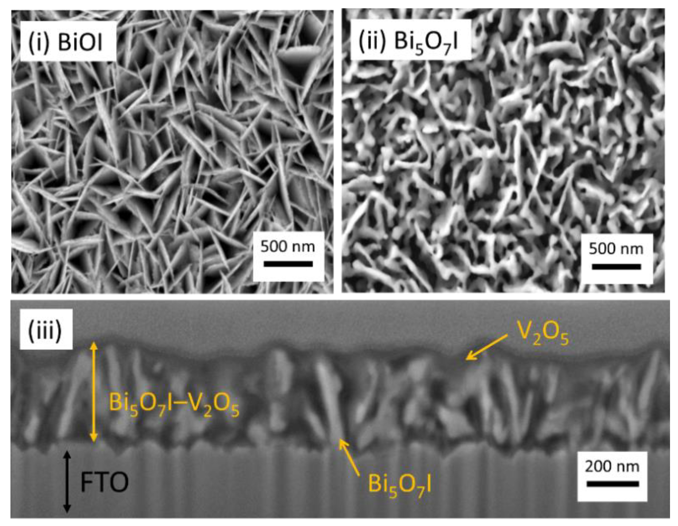
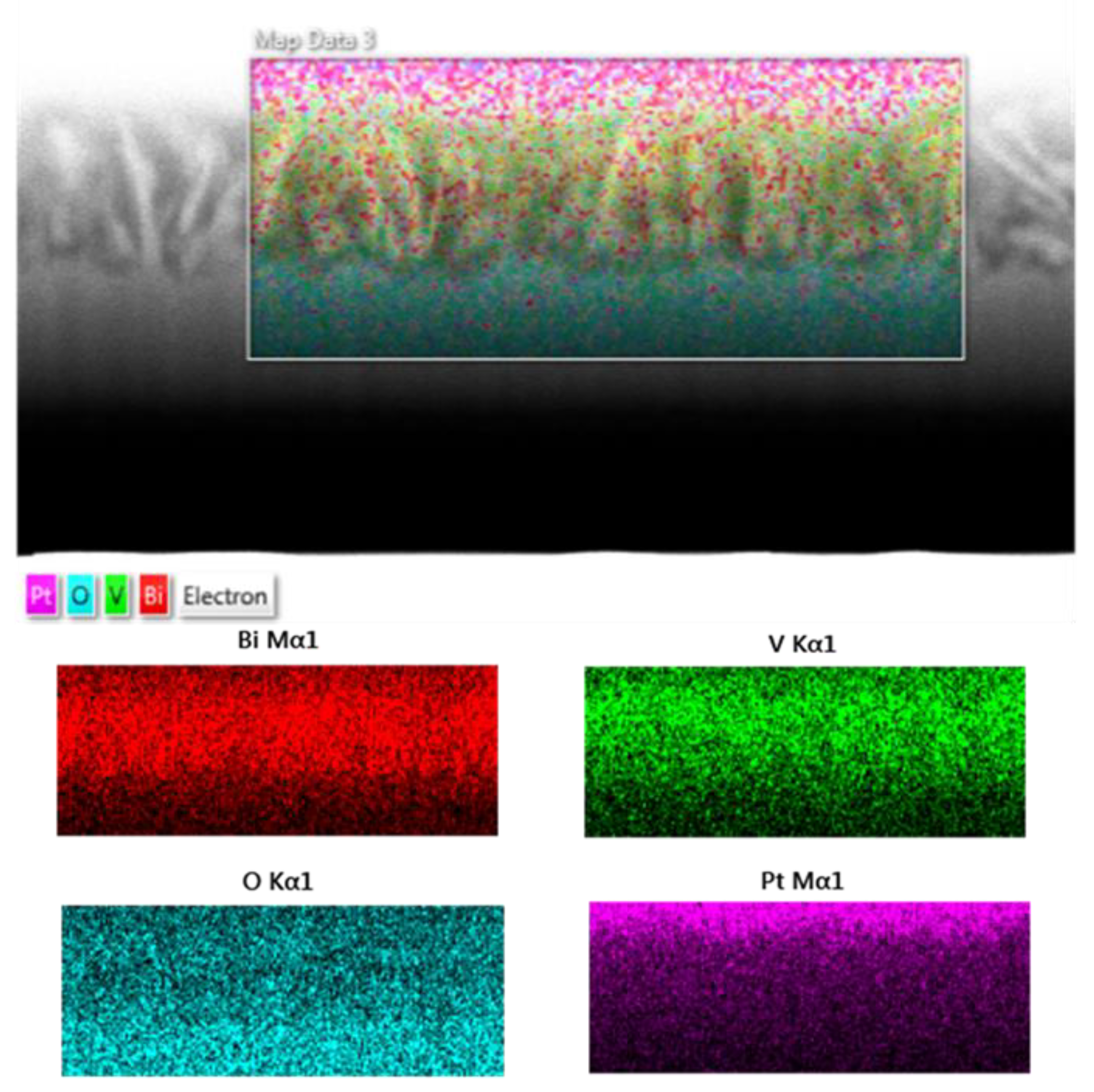
2.1.1. Formation of BiVO4

Choi et al. developed the two-step BiVO4 synthesis method, which gave an excellent performance for PEC water oxidation [13,15]. In the Choi method, in Step 1, BiOI was formed by electrochemical deposition. In Step 2, the V source (e.g., V2O5, VO(acac)2, etc.) solution was placed by drop-casting on the BiOI film. Following this, the Bi–V–O reaction was processed by heating at high temperatures (350–650 °C) for 2–5 h in air to convert the BiOI–V precursor into BiVO4. In our tests, when using the method of placing a solution of vanadium species on the BiOI film by drop-casting, the BiVO4 thin film obtained after the Bi–V–O heat treatment often broke. There is still room for improvement in the BiVO4 crystal growth process for PEC properties. First, we focused on the components of the electrodeposition bath solution. It is well known that, in the field of electrochemical deposition research, lactic acid (C3H6O3) in the deposition bath forms complexes with transition metals (e.g., Cu) and affects the crystal growth in a particular orientation [25]. Figure 1 shows the flowchart for preparing our BiVO4 photoanode; the procedure in Step 1 is similar to the Choi method [13,15]. As a standard for this study, the aqueous deposition bath solution in Step 1 contained 60 mmol/L lactic acid. In Step 1, the complexes of Bi with iodide [BiI4] and lactic acid [Bi(C3H4O3)2(C3H5O3)]2− were first produced at pH 1.2 in the aqueous solution bath (Equations (1) and (2)). Then, the solution of the Bi3+ species was mixed with an ethanol benzoquinone solution. The bath solution was stirred overnight for complex formation and pH stabilisation. Some of the benzoquinones were reduced to hydroquinone, thereby shifting the pH value towards alkalinity (pH 3.6–4.0). During Step 1, cathodic deposition, benzoquinone was actively reduced to hydroquinone (Equation (3)). At the same time, the concentration of the hydroxide ions (OH) increased on the working electrode and reacted with the bismuth iodide [BiI4] species to form BiOI (Equation (4)). Next, in our method, to reduce the hydrophobicity of the film surface, the BiOI film was heated to 450 °C for 1 h to generate penta-bismuth hepta-oxide iodide (Bi5O7I). In Step 2, an ethanol aqueous solution of vanadyl sulphate (VOSO4) was utilised as the electrodeposition bath, and VO2+ was oxidised to amorphous V2O5 (Equation (5)) throughout the Bi5O7I film during the anodic deposition. This process allowed an aqueous solution of vanadium source to penetrate among the Bi5O7I flakes to produce V2O5. This process is different from previous reports. The as-deposited films were annealed at 475 °C for 1 h in air to convert the Bi5O7I–V2O5 precursor to BiVO4. The pure BiVO4 was obtained after washing with an aqueous KOH solution (0.5 mol/L) to remove residual V2O5. It seems that the adhesion between the FTO substrate and the BiVO4 film was strong. The BiVO4 film prepared by the electrodeposition method could not be completely removed from the FTO substrate by wiping it strongly with tissue paper.
Bi3+ + 4I → [BiI]
Bi3+ + 3C3H6O3 → [Bi(C3H4O3)2(C3H5O3)]2− + 5H+
Catalysts 11 00136 i001
[BiI4] + 2OH → BiOI +H2O + 3I
2VO2+ + 3H2O → V2O5 + 6H+ + 2e
BiOI, Bi5O7I, and BiVO4 were synthesised according to the procedure shown in the flowchart in Figure 1. The absorbances of the BiOI, Bi5O7I, and BiVO4 films agreed with those in the previous literature [15,26] (Figure S1). BiOI and Bi5O7I produced by Step 1 were confirmed by X-ray diffraction (XRD) (Figure 2A). In the new synthesis Step 2 (Figure 2B), the as-deposited V2O5 was amorphous and could not be detected by XRD. However, after mild heating for 1 h at 475 °C, the XRD pattern of a mixed pattern of BiVO4 and V2O5 was observed. Thereafter, the excess V2O5 was removed with an aqueous KOH solution. In Figure 2 (Bv), the paired peaks, which are characteristic of the scheelite-structured monoclinic BiVO4, appeared around 19° and 35° of 2θ.
Regarding morphological observations, the BiOI film was relatively hydrophobic because of the physical structure of the 2D BiOI flake (Figure 3i and Figure S2i). After the heat treatment at 450 °C for 1 h, the BiOI turned to Bi5I7O. The sharp BiOI flakes became the rounded tip of Bi5O7I, which caused a difference in surface height, and succeeded in reducing the hydrophobicity of the film surface (Figure 3ii and Figure S2ii). The cross-sectional image of the Bi5O7I–V2O5 film (Figure 3iii) displays the Bi5O7I flakes surrounded by the as-deposited amorphous V2O5. The thickness of the Bi5O7I–V2O5 thin film was approximately 350 nm.
The atomic distribution of Bi and V was performed by energy-dispersive X-ray spectroscopy (EDS) mapping to investigate whether the Bi–V–O conversion reaction could proceed throughout the thin film at the same time. In Figure 4, evidently, the EDS elemental mapping images of the Bi5O7I–V2O5 film shows V atoms were densely and uniformly dispersed all over the Bi5O7I film. The atomic ratio of Bi to V was 1:2.17, which contained extra V2O5 for BiVO4 conversion.
During the annealing process at 475 °C for 1 h, BiVO4 particles were formed by reacting the V2O5 and the Bi5O7I flake on the FTO substrate. Since the Bi and V atoms were uniformly present, it is considered that the Bi–V–O conversion reaction occurred throughout the Bi species thin film and at the same time. Consequently, a porous structured thin film was created with nanosized BiVO4 particles. In Figure 5, the shape of the BiVO4 nanoparticles was not the same as the worm-like particles prepared by the Choi method [13,15,16]. These images indicate that the BiVO4 nanoparticles were highly monodispersed. If extra agglomerates of BiVO4 particles were formed on the surface by the excessive progress of Bi–V–O reaction during heating process, the agglomerates of BiVO4 particles can act as carrier traps that might reduce the photocurrent [16]. However, Figure 5a shows that no unwanted BiVO4 particle agglomerates on the surface of the BiVO4 thin film. Furthermore, the EDS composition analysis of the pure BiVO4 film resulted that the rational atomic ratio of Bi to V was 1:1.08 (Figure S3).

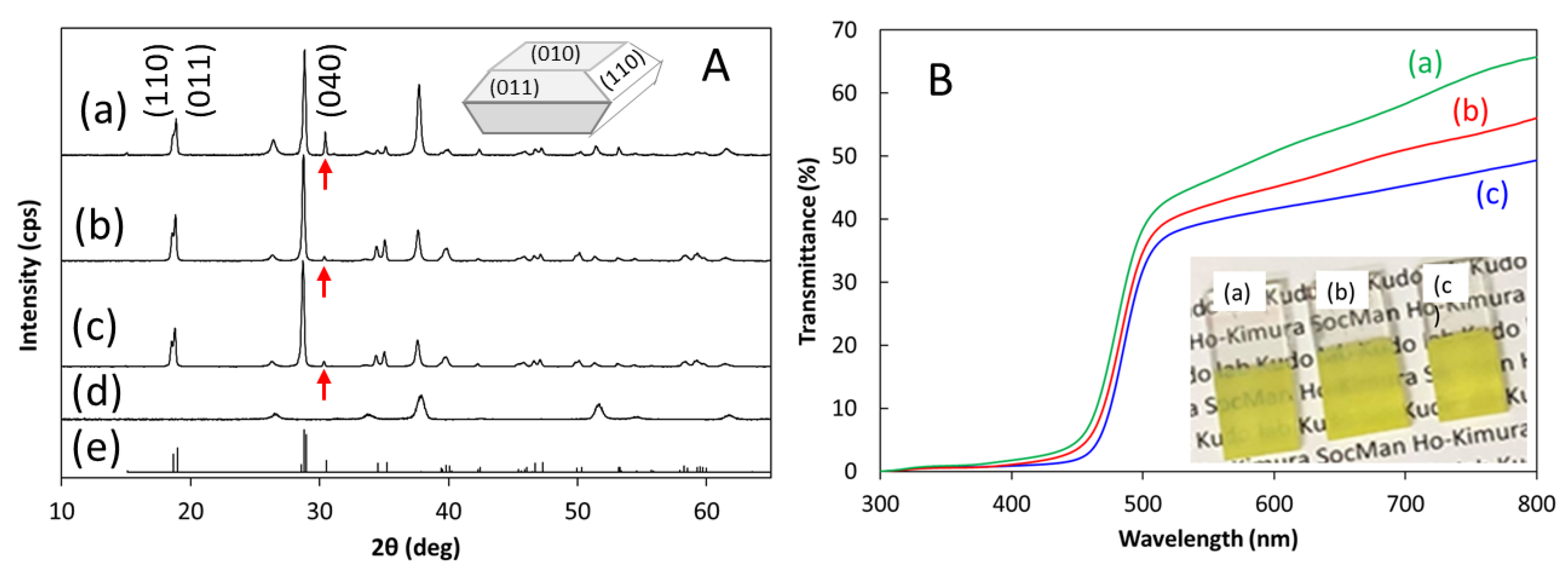
2.1.2. Effect of Adding Lactic Acid

To investigate the effect of the addition amount, BiVO4 films were prepared by changing the addition amount of lactic acid according to the procedure shown in Figure 1. The XRD patterns of the BiVO4 films all showed monoclinic scheelite-structure with a (040) peak of about 31° at 2θ (Figure 6A). In particular, the XRD pattern of BiVO4 formed using the electrodeposition bath contained 60 mmol/L lactic acid exhibited increased (040) peak intensity. The (040) peak of the XRD pattern corresponds to the (010) facet. It is presumed that BiOI produced in the presence of an appropriate amount of lactic acid strongly adhered to the FTO in the specific orientation, hence the BiVO4 (010) facets exposed favourably after Bi5O7I reacted with V2O5 at 475 °C.
The BiVO4 particles converted by the BiOI–(V species) precursors [15] on an indium tin oxide (ITO) substrate held a comparatively low light transmittance of ca. 30% at 600 nm [16]. This transmittance percentage was equivalent to the case without lactic acid in this study. As shown in Figure 6B, the BiVO4 thin film prepared using the electrodeposition bath containing 60 mmol/L lactic acid shows the highest transmittance spectrum and has a transmittance of 52% at 600 nm. It is considered that the transmittance was improved because of atomic arrangement of the (010) oriented BiVO4. From the perspective of transmittance, our BiVO4 photoanode will also be suitable for practical application of a PEC tandem cell system.

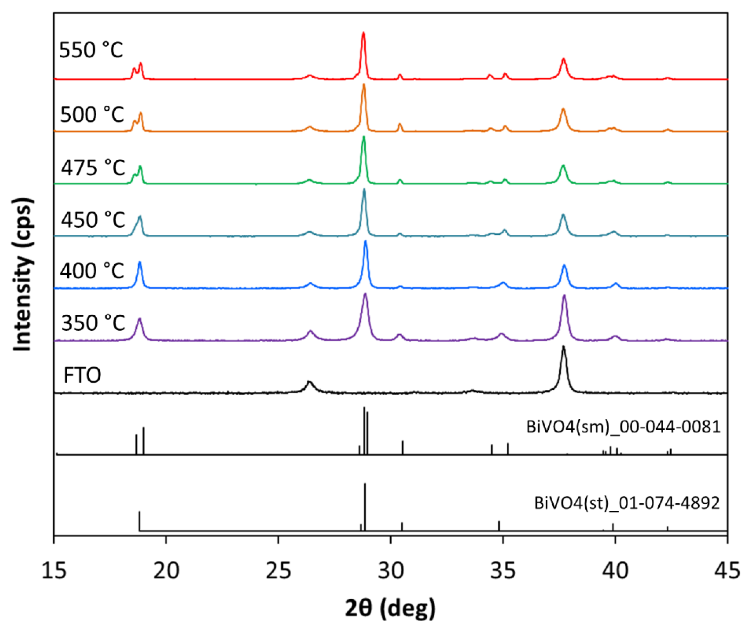
2.1.3. Conversion Temperature from Bi5O7I–V2O5 Precursor to BiVO4
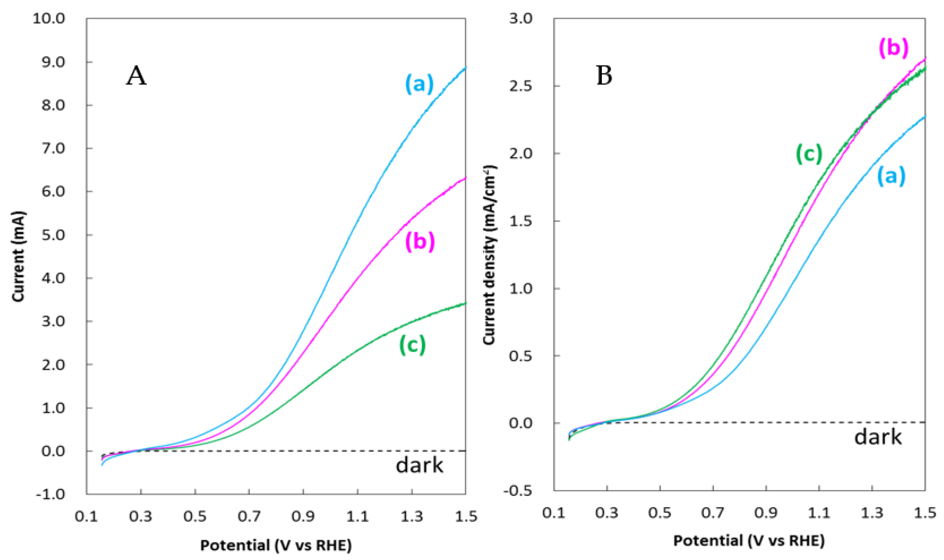
The effect of temperature on the conversion of Bi5O7I–V2O5 precursors of Sample (iii) in Figure 1 to BiVO4 crystals is especially important. The annealing process of the Bi–V–O conversion reaction was investigated from 350 to 550 °C. In the XRD patterns (Figure 7 and Figure S4), all the thin films exhibited the (040) peak after heat process at 350–550 °C. For the paired peak, a feature of the scheelite-structured monoclinic BiVO4, the required temperature for the Bi–V–O annealing process was 450 °C or higher. A tetragonal BiVO4 was established by heating at 400 °C or lower. The BiVO4 thin film prepared at 350 °C exhibited relatively low crystallinity.
In the SEM images (Figure S5), it was observed that the particle size of BiVO4 increased as the temperature was increased. These particles exhibited high uniformity in the size and shape of each film. Furthermore, there was no extra agglutination of BiVO4 particles on the surface of these films. At the process temperature from 350 to 475 °C, the nanoscale particles created porous structured layer on the FTO substrate. Noticeably, these thin films possessed a relatively large surface area. Contrarily, the aggregation of the BiVO4 particles was initiated at 500 °C, and the porous structure became non-porous. At 550 °C, completely large particles were remodelled into a non-porous-layered structure. Therefore, when the conversion temperature was extremely high, the surface area where the water oxidation reaction occurs decreased. To prevent the agglutination of ultrafine particles, it is vital to complete the conversion reaction in a short time such as 1 h. Additionally, the light scattering between the large particles occurred in the 500 and 550 °C treated thin films, and the absorbance increased in the long-wavelength region (Figure S6). The samples treated at 450 and 475 °C possessed the appropriate band gaps for BiVO4 and enabled the absorption of visible light of up to 520 nm.

2.2. PEC Properties

2.2.1. Effect of Adding Lactic Acid

The photocurrent density–potential (J–V) curves of BiVO4 films grown in the deposition bath with varying lactic acid concentrations were measured (Figure 8). From the photocurrent density, it was observed that the optimum concentration of lactic acid added to the deposition bath was 60 mmol/L. This result may be related to the XRD findings in Figure 6A. BiVO4 crystals with exposed (010) facets corresponding to the (040) peak of the XRD pattern were reported to exhibit higher photocatalytic activity for water oxidation than without (040) peak [27]. However, even with high peak intensities, the improvement in water oxidation reaction did not increase proportionally [27].
On the other hand, the (010) and (110) crystal facets of monoclinic BiVO4 have been reported to be active reducing and oxidising sites, respectively [28]. The large (010) facet provided rapid charge separation and suppressed both bulk and surface recombination [28]. In this study, the (010) oriented BiVO4 crystals enhanced the photocurrent density by improving electron transport.

2.2.2. Bi–V–O to BiVO4 Conversion Temperature

The temperature-dependent PEC properties of the Bi–V–O annealing process were investigated from 350 to 550 °C (Figure 9A). The BiVO4 photoanodes processed by the Bi–V–O annealing at 450 and 475 °C showed excellent photocurrent densities. Figure 9B shows the applied bias photo-to-current efficiency (ABPE) calculated from the corresponding J–V curves. Generally, the average maximum ABPE of bare BiVO4 photoanode is 0.3% or less in the range of about 0.9–1.0 V vs. RHE [29,30]. In the present study, for the Bi–V–O annealing process at 475 °C, the ABPE of the bare BiVO4 photoanode reached 0.37% at 0.9 V vs. RHE, which was the greatest of our tests. This is probably because the porous-structured BiVO4 photoanode was a highly crystalline scheelite-structured monoclinic system.
Furthermore, the open circuit (OC) potential of each photoanode was measured in the dark and under illumination (Figure S7A) because the difference in the OC potentials between dark and light conditions is related to the photovoltage. Further, the onset potential is considered to be related to the light OC potential. The BiVO4 photoanode prepared by Bi–V–O annealing process at 475 °C recorded the most negative light OC potential and the biggest difference (Figure S7B). It can be inferred that the photoanode produced at 475 °C possessed a higher photovoltage than the other temperatures. These characteristics discussed above are consistent with those of the PEC photoresponse.

2.2.3. PEC Properties of the Optimised BiVO4 Photoanode

The optimised bare BiVO4 photoanode was obtained by using the electrodeposition bath containing 60 mmol/L lactic acid and treating the Bi–V–O conversion process at 475 °C. The photocurrent density of water oxidation attained 2.2 mA/cm2 at 1.23 V vs. RHE (Figure 10A). In addition, using an electrolyte with hole scavenger K2SO3, the J–V curve shifted to the negative potential region and the photocurrent density increased significantly. It is considered that the oxidation of K2SO3 reduced the charge recombination on the surface of BiVO4.
To quantify the contributions of the suppressing bulk or surface recombination, charge separation efficiency (ηsep) and surface transfer efficiency (ηtrans) of the BiVO4 photoanode were calculated by the following equation: [22,31]
JH2O = Jabsorbed × ηtrans × ηsep
JK2SO3 = Jabsorbed × ηsep
ηsep = JK2SO3/Jabsorbed
ηtrans = JH2O/Jabsorbed × ηsep = JH2O/JK2SO3
where JH2O is the measured photocurrent density and Jabsorbed is the photon absorption rate (expressed as a photocurrent density). The calculated Jabsorbed of the BiVO4 photoanode was specified as 4.45 mA/cm2 [15]. JH2O and JK2SO3 are the photocurrent densities collected in the 0.5 mol/L potassium borate electrolyte without and with 0.2 mol/L K2SO3, respectively. When K2SO3 is added into an electrolyte, it acts as a hole scavenger. In the presence of K2SO3 in electrolyte, the surface transfer efficiency is assumed to be 100%.
For comparison, in general, the average charge separation efficiency (ηsep) of bare BiVO4 photoanode was lower than 45% at 1.23 V vs. RHE [30,31], and the average surface transfer efficiency (ηtrans) was ca. 35% at 1.23 V vs. RHE [30,32,33]. As shown in Figure 10B, the ηsep and ηtrans of the bare BiVO4 increased to 56% and 86% at 1.23 V vs. RHE, respectively. This is likely due to the uniform particle size and composition of the morphologically controlled BiVO4 crystals, which increased the efficiency of the water photooxidation reaction.
The exposed (010) facets are able to provide rapid electron transfer, thus improving the PEC water oxidation on BiVO4 by smooth charge separation [27,28]. Our results indicate that lactic acid contributed to the growth of (010) oriented crystals. In addition, by controlling the Bi–V–O reaction temperature, particles of appropriate size were supplied. The hole diffusion length of BiVO4 is estimated as 70 nm [8]; nanosized particles are more advantageous for the movement of holes to the surface. Consequently, the charge recombination was reduced, thereby resulting in an increased photocurrent density even with frontal illumination.
The photocurrent from the back illumination was slightly lower than that from the front illumination (Figure 10C). In many reports, large BiVO4 crystals size and film thickness resulted in higher photocurrents at the back exposure than at the front [34,35]. In contrast, our BiVO4 film was composed of nanosized crystals, was thin, and showed high transmittance. In the case of the back illumination, there was probably a loss of light by the reflection on the glass surface of the FTO substrate.

2.2.4. Effect of Cocatalyst

It is known that surface modification of BiVO4 with a cocatalyst can reduce the recombination of the surface charges and accelerate the rate of oxygen generation [21,24]. It was confirmed that BiVO4 utilised in this study was also influenced by the loading of cobalt (II, III) oxide (Co3O4) cocatalyst (Figure 11A). The BiVO4/Co3O4 photoelectrode was obtained by drop-casting an ethanol cobalt nitrate solution to the BiVO4 photoanode surface and heating it to 350 °C for 1 h in air. The cobalt nitrate decomposed into Co3O4 during heating process at 350 °C [23].
The photocurrent of the bare BiVO4 and BiVO4/Co3O4 photoelectrodes were 2.2 and 2.9 mA/cm2 at 1.23 V vs. RHE, respectively (Figure 11A). The Co3O4 cocatalyst exerted a great influence on the negative potentials shift of the J–V curve, which was a characteristic of the effect of cocatalysts. Moreover, when using the electrolyte with K2SO3 of a hole scavenger, a higher photocurrent of 3.8 mA/cm2 at 1.23 V vs. RHE was achieved.
Owing to the effect of the Co3O4 cocatalyst, the maximum ABPE of water oxidation increased from 0.37% at 0.9 V to 1.03% at 0.6 V vs. RHE (Figure 11B). The Co3O4 cocatalyst effectively enhanced the kinetic water oxidation on the BiVO4 photoanode, and a higher efficiency was obtained with moderate bias.
The incident photon-to-current conversion efficiency (IPCE) measurements were performed by monochromatic lights between 370 and 560 nm to ascertain the light conversion efficiency (Figure 12). Typically, the average IPCE value at 420 nm performed at 1.23 V vs. RHE is lower than 20% for bare BiVO4 [11,35,36]. In the present study, the IPCEs of the bare BiVO4 photoanode were 7.5% and 23.2% at 0.6 and 1.23 V vs. RHE, respectively, at 420 nm. Further, the IPCEs of the BiVO4/Co3O4 photoanode exhibited remarkable increase to 23.8% and 37.5% at 0.6 and 1.23 V vs. RHE, respectively, at 420 nm. Both BiVO4 photoanodes with and without Co3O4 cocatalyst presented photoresponse in the visible light region, which was consistent with the absorption spectrum of BiVO4.

2.2.5. Impact of the Photoelectrode Area

Scale-up of photoelectrodes for the practical application of hydrogen generation from PEC water splitting is a key issue. In many reports, the photoelectrodes used were often smaller than 1 cm2. These could not satisfy the actual requirements. According to previous reports [18,19], the decrease in photocurrent density by electrode scale-up is mainly due to the resistance of the FTO substrate. Here, to find the size that causes the resistance loss of the FTO substrate in this study, we probed the PEC water oxidation on the BiVO4 electrodes with larger than 1 cm2 from 1.3 to 3.9 cm2. The current–potential (I–V) curves of the bare BiVO4 photoanodes are shown in Figure 13A. Photocurrents increased with the area of the photoelectrodes. The maximum photocurrent reached 9 mA at 1.5 V vs. RHE with the 3 × 1.3 cm2 photoanode. Nevertheless, the 3 × 1.3 cm2 photoanode showed a little decrease in its photocurrent density (Figure 13B). The 1 × 1.3 and 1.8 × 1.3 cm2 photoelectrodes were both retained at high photocurrent densities of 2.2 mA/cm2 at 1.23 V vs. RHE. No photocurrent loss was observed in the FTO glass substrate with an area up to 2 cm2 when using our BiVO4 synthesis method.

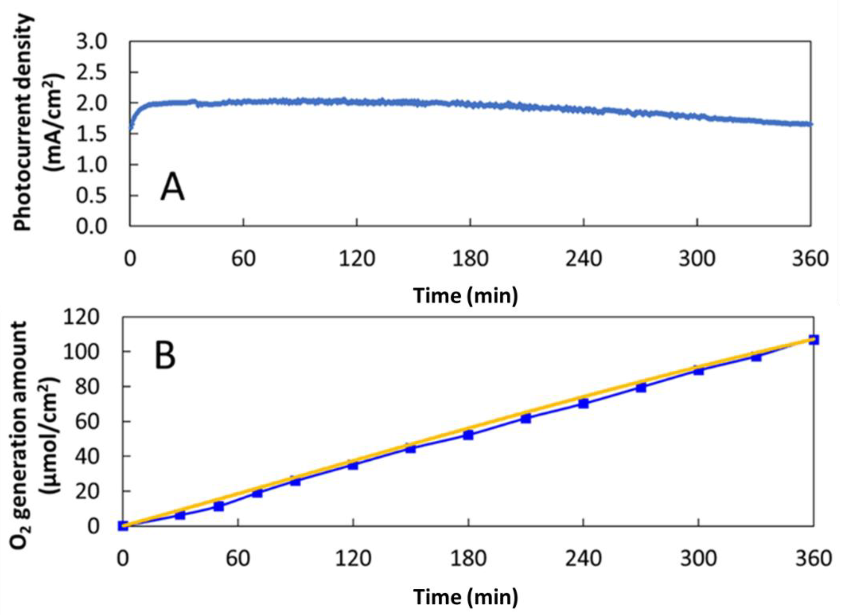
2.3. Solar-Driven Water Oxidation on the Bare BiVO4 Photoanode

To confirm that the photocurrent actually causes water oxidation without any other side reaction on the bare BiVO4 photoanode, PEC oxygen generation was measured by an online gas chromatography system when applying a constant potential of 1.23 V vs. RHE under solar simulated light of 100 mW/cm2 irradiation. Six hours after the reaction, the stable photocurrent density dropped slightly from about 2 to 1.7 mA/cm2 (Figure 14A). The corresponding oxygen generated was more than 100 μmol/cm2 in 6 h, agreeing with the calculated value of the photocurrent density (Figure 14B), and its Faradaic efficiency was almost 100%. Thus, it was confirmed that the photocurrent was consistent with the solar-driven water oxidation on the bare BiVO4 photoanode.

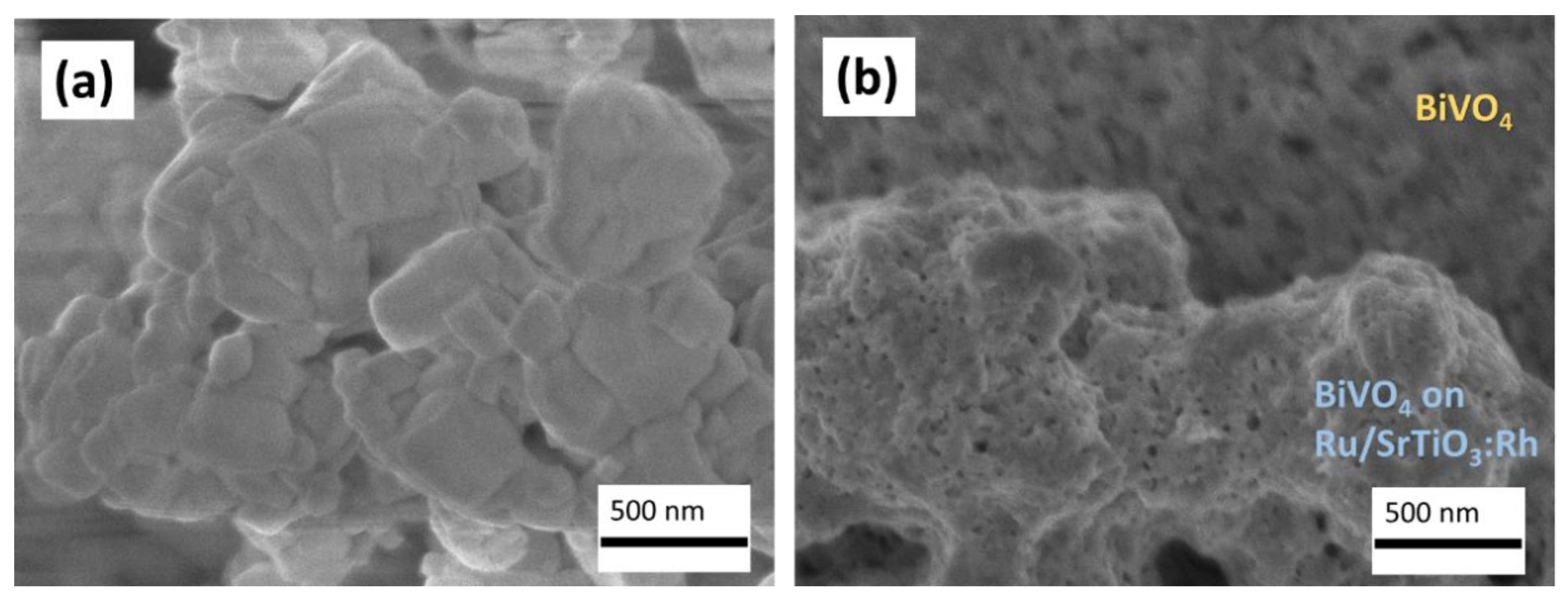
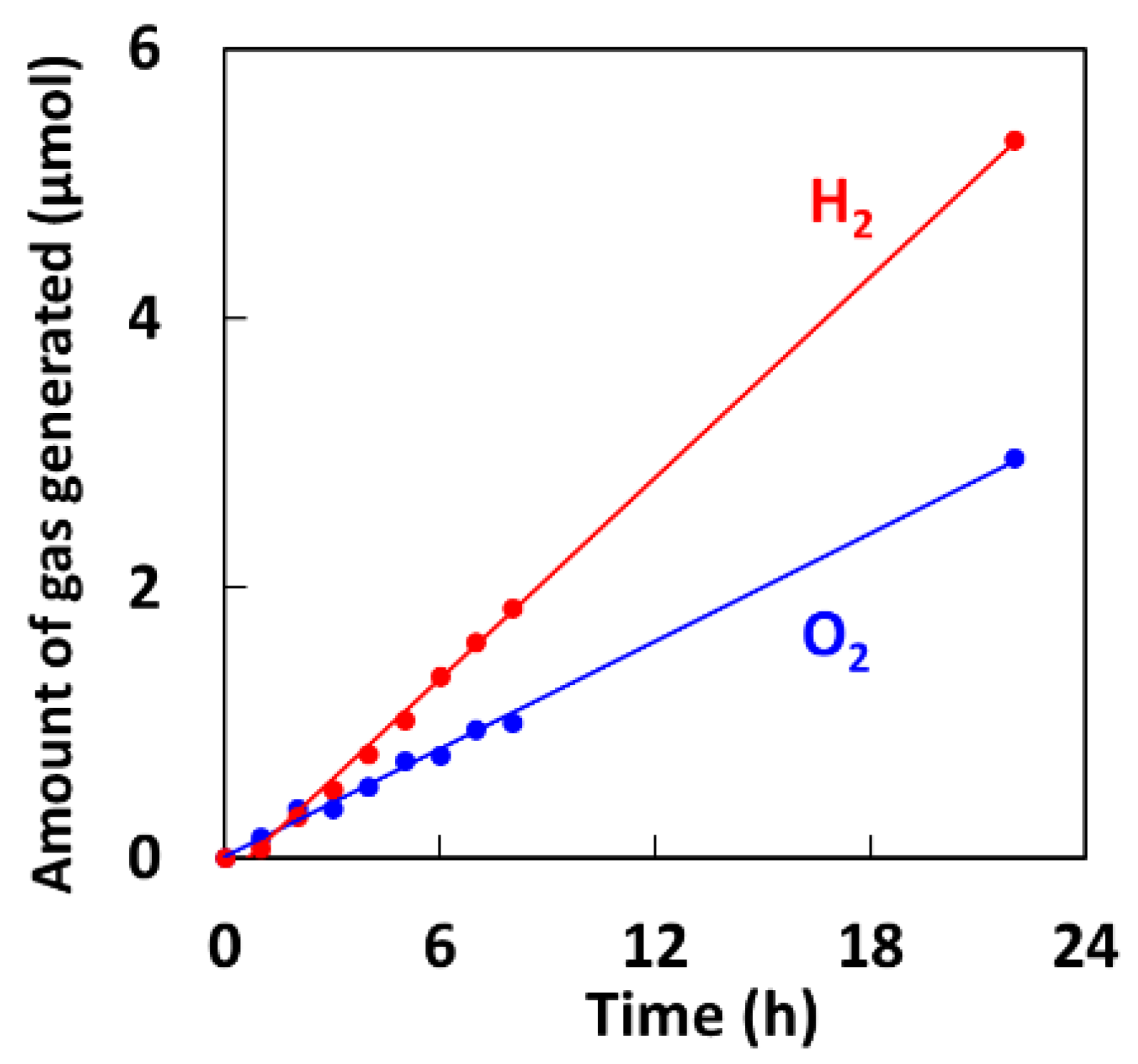
2.4. Overall Water Splitting on the Ru/SrTiO3:Rh–BiVO4 Sheet

Our BiVO4 is a promising candidate for unassisted water splitting on p-n semiconductor photocatalyst sheet because of its high PEC photocurrent and transmittance. Here, as an example of the application of the present BiVO4 synthesis method, visible-light-driven water splitting was performed with a Ru/SrTiO3:Rh–BiVO4 sheet. The details of the preparation of the photocatalyst sheet are presented in the experimental Section 3. Materials and Methods.
The XRD patterns of the prepared Ru (0.7 wt%)/SrTiO3:Rh (1%)–BiVO4 sheet was measured and matched with the reference data [37] (Figure S8). The morphological observations indicated that the electrochemically deposited BiVO4 particles adhered well on the surface of the Ru/SrTiO3:Rh particles to form the Ru/SrTiO3:Rh–BiVO4 sheet (Figure 15). The weight of Ru/SrTiO3:Rh plus BiVO4 was an average of 3 mg/cm2 and the sheet area was 12 cm2. Figure 16 shows a time course of water splitting using the Ru/SrTiO3:Rh–BiVO4 sheet. Evidently, the visible-light-driven water splitting occurred on the Ru/SrTiO3:Rh–BiVO4 sheet in deionised water without a redox mediator. It was confirmed that the stoichiometric ratio of hydrogen and oxygen was 2:1. After 22 h of water splitting, there was no change in the appearance before and after the reaction.

3. Materials and Methods

Film growth. The nanoscale porous BiVO4 photoanodes (area = 1.0 × 1.3 cm2) were fabricated on a conducting fluorine-doped tin oxide (FTO) coated glass (FTO-P003; <15 ohm/sq; Kaivo; Zhuhai, Guangdong, China) by a two-step electrochemical deposition at room temperature (24 ± 2 °C). A potentiostat (Hokuto Denko, HZ7000, Tokyo, Japan) with a two-electrode configuration cell was utilised for the electrochemical deposition. A 2 cm2 platinum gauze was used as the counter electrode.
In Step 1, the electrodeposition bath was an aqueous solution (30 mL) containing 0.0075 mol/L bismuth (III) nitrate pentahydrate (Bi(NO3)3·5H2O, 99.5%, Kanto Chemical Co., INC., Tokyo, Japan), 0.4 mol/L potassium iodide (KI, 99.5%, Kanto Chemical Co., INC., Tokyo, Japan), and 60 mmol/L lactic acid (C3H6O3, 90%, Acros Organics, Fisher Scientific worldwide company, Geel, Belgium) with adjusted pH to 1.2 by nitric acid (HNO3, 98.0%, Kanto Chemical Co., INC., Tokyo, Japan). Next, 20 mL of ethanol containing 0.15 mol/L p-benzoquinone (97%, Kanto Chemical Co., INC., Tokyo, Japan) were slowly added into the Bi3+ species solution. The mixed solution was stirred overnight until a stable pH of 3.6–4.0. The BiOI was deposited at a constant bias of −0.3 V vs. Pt for 15 min. The as-deposited BiOI film was rinsed by deionised water and air-dried. To obtain the crystalline Bi5O7I films, the BiOI films were annealed in air for 1 h at 450 °C (ramping rate = 5 °C/min).
The same setup (as in Step 1) was employed for Step 2 deposition. To deposit the amorphous V2O5 on the Bi5O7I film, an ethanol/water solution (ratio 1:1) of 0.22 mol/L vanadyl sulphate hydrate (VOSO4·nH2O; >55%; Kanto Chemical Co., INC., Tokyo, Japan) was utilised as the electrodeposition bath. The formation of amorphous V2O5 can be achieved on the Bi5O7I film or an FTO glass by anodic deposition, e.g., at a current of 0.5–2 mA/cm2 and a certain time. In this study, V2O5 was deposited on the Bi5O7I film at a constant current of 1 mA/cm2 for 15 min. The as-deposited films were annealed in air at varying temperatures at 350, 400, 450, 475, 500, and 550 °C (ramping rate = 5 °C/min) for 1 h. In the annealing process, Bi5O7I and the amorphous V2O5 reacted to form crystallised BiVO4 and V2O5. To remove the residual V2O5 on BiVO4, the BiVO4 photoelectrodes were immersed in a 0.5 mol/L KOH aqueous solution for 30 min with gentle stirring. Following this, these films were washed with deionised water and wiped with tissue paper (KimWipes s-200, Kimberly Clark Corp., Irving, Texas, USA) and then air dried.
The cobalt oxide cocatalyst was placed on the BiVO4 films by drop-casting 3 μL/cm2 of 80 mmol/L Co(NO3)2·6H2O (Wako Pure Chemical; 99.5%, Osaka, Japan) ethanol solution, which was followed by calcination for 1 h at 350 °C (ramping rate = 5 °C/min) in air.
Film characterisation. The morphologies of the BiVO4 films were characterised by field-emission SEM JEOL JSM-6700F microscope (JEOL, Tokyo, Japan) and FIB-SEM (Zeiss Crossbeam 540, Carl Zeiss, Oberkochen, Germany). The microscope was equipped with an EDS unit (Oxford Instruments, silicon Drift Detector-X-MaxN, Abingdon, Oxfordshire, UK). The phase identification was achieved by XRD utilising a Rigaku (MiniFlex 600, Rigaku, Tokyo, Japan) X-ray diffractometer equipped with Cu Kα (40 kV and 15 mA; λ = 1.540619 Å) radiation and operated in 2θ scan modes from 10° to 65°, 0.02° step-size, 5° per min. The adopted result was the average value after five measurements. To confirm the phases of BiOI, Bi5O7I and BiVO4, reference JCPDS files for BiOI (JCPDS No. 00-010-0445), Bi5O7I (JCPDS No. 01-071-3024), and BiVO4 (JCPDS No. 00-044-0081) were cited. The ultraviolet–visible absorption spectra of the photoanodes were analysed on a spectrophotometer (JASCO V-780, JASCO, Tokyo, Japan) with an integrating sphere that was operated in the transmission mode to minimise a negative effect by light scattering.
PEC measurements. The PEC properties of the BiVO4 films were measured under AM1.5G type solar simulated light (Asahi spectra, HAL320, Tokyo, Japan) with a spotlight area of 3 × 3 cm2. The light output was calibrated to 100 mW/cm2 by a power meter (Asahi spectra, CS-20, Tokyo, Japan) The PEC performance of the photoanodes was evaluated in a three-electrode configuration utilising a potentiostat (Hokuto Denko, HSV110, Tokyo, Japan). The reference electrode was Ag/AgCl in saturated KCl, and a 2 cm2 Pt gauze was utilised as the counter electrode. As a standard, the films were illuminated from the BiVO4 side (front). The scan rate for linear sweep voltammograms was set to 20 mV/s. The electrolyte comprised an aqueous solution of 0.5 mol/L boric acid that was pH-adjusted to 9.5 with potassium hydroxide. All the potentials in this work were reported against the RHE calculated from those relative to the Ag/AgCl reference electrode by Nernst equation, ERHE = EAg/AgCl vs. NHE + EAg/AgCl + 0.059 pH. Here, ERHE is the converted potential vs. RHE. EAg/AgCl vs. NHE is the correction coefficient for Ag/AgCl reference electrode regarding normal hydrogen electrode (NHE) and was taken as 0.197 at 25 °C. EAg/AgCl is the experimentally measured potential against the Ag/AgCl reference.
Further, ABPE (%) was calculated using Equation (10):
ABPE = Δ J   ×   ( 1.23 V ) P × 100
where ΔJ (Jlight − Jdark (mA/cm2)) is the measured photocurrent density, V (vs. RHE) is the applied bias, and P is the incident light intensity (100 mW/cm2).
The incident photon-to-current conversion efficiency (IPCE) measurements were carried out with coloured filters from 370 to 560 nm by measuring the photocurrent produced under chopped monochromatic light irradiation. The monochromatic light intensities were measured by a photodiode power sensor (OPHIR Japan Ltd., Tokyo, Japan). The IPCE (%) was then calculated using Equation (11):
IPCE ( λ ) = 1240 j ( λ ) I o ( λ ) × λ × 100
where λ is the wavelength of incident monochromatic light (nm), j(λ) is the difference between dark current density and photocurrent density under illumination at wavelength λ (mA/cm2), and I0(λ) is the incident light intensity at wavelength λ (mW/cm2).
Measurement of the oxygen produced by PEC water splitting. PEC water splitting on the BiVO4 film was performed at an applied potential of 1.23 V vs. RHE under solar simulated light (Asahi spectra, HAL320, Tokyo, Japan) at 100 mW/cm2 irradiation (Asahi spectra, CS-20). The PEC properties were evaluated using a potentiostat (Hokuto Denko, HZ-7000, Tokyo, Japan). An airtight three-electrode configuration with a compartmental H-type cell that was separated by a membrane (DuPont, Nafion 117, Wilmington, Delaware, USA) was employed. Incidentally, using a membrane separation cell could prevent the occurrences of reverse reactions. The reference electrode was Ag/AgCl in saturated KCl, and a Pt wire (diameter = 0.5 cm, length = 6 cm) was utilised as the counter electrode. Furthermore, 0.5 mol/L potassium borate (buffered at pH 7.5) was utilised as an electrolyte. The amount of evolved oxygen on the BiVO4 photoanode was recorded by an online gas chromatograph (GC) (Shimadzu GC-8A, Kyoto, Japan), TCD detector, MS-5 Å column, oven at 70 °C, argon carrier). Argon was the carrier gas from the reactor to the GC instrument at a flow rate of 15 mL/min.
Preparation and water splitting of the photocatalyst sheet. Rh-doped SrTiO3 powder was prepared by a previously reported solid-state method [37]. In a typical procedure, SrCO3 (Kanto Chemical, 99.9%, Tokyo, Japan), TiO2 (High Purity Chemicals, 99.9%, Tokyo, Japan), and Rh2O3 (Wako Pure Chemical, Tokyo, Japan) were mixed in the Sr/Ti/Rh ratio of 1.07:0.93:0.01. The mixture was calcined in air for 1 h at 900 °C, after which the powder was mingled well and calcined again for 10 h at 1100 °C. Ru was utilised as a cocatalyst to SrTiO3 for hydrogen evolution. Ru (0.7 wt%) was loaded on SrTiO3:Rh by photo-assisted reduction in an aqueous 10 vol% methanol solution containing RuCl3 (Wako Pure Chemical, 85.0%). The Ru/SrTiO3:Rh photocatalyst was collected by filtration and washed with distilled water. The photocatalyst powder (100 mg) was added to 0.3 mL of a mixture of 1:2 acetylacetone (Kanto Chemical, 99.5%) and deionised water, and then sonicated for 5 min. The resulting paste was placed on an FTO glass substrate. Next, to remove the organic solvent, the photocatalyst sheet was heated in air for 2 h at 200 °C. By the method described above (Figure 1), BiVO4 was deposited on the Ru/SrTiO3:Rh sheet. The overall water-splitting experiment on the Ru/SrTiO3:Rh–BiVO4 sheet was performed in 120 mL of deionised water without a redox mediator. A top-irradiation cell with a Pyrex window was utilised after degassing by applying a vacuum and purging with argon. The setup was returned to reduced pressure (70 Torr) and irradiated with a 300 W Xe arc-light source (PerkinElmer; CERMAX PE300BF, Waltham, Massachusetts, USA) with a long-pass filter (λ > 420 nm). The amounts of evolved hydrogen and oxygen were determined by an online GC (Shimadzu; GC-8A, TCD, MS-5Å column, oven at 50 °C, argon carrier).

4. Conclusions

We developed a highly efficient BiVO4 photoanode synthesis method for PEC water oxidation by a simple electrochemical procedure. According to our method, the electrochemical deposited amorphous V2O5 was able to spread densely among the precursor Bi5O7I flakes. Therefore, during the appropriate annealing process of Bi–V–O conversion at 475 °C for 1 h, the BiVO4 was formed along the shape of the Bi5O7I flakes by converting with the amorphous V2O5, thereby creating a porous structured film. Since the Bi–V–O reaction occurred throughout the thin film as the same time, the BiVO4 particles were highly monodispersed nanoscales.
It is considered that the BiVO4 formation control by the addition of lactic acid strengthened the atomic arrangement of the (010) orientation and improved the transmittance of the BiVO4 photoanode thin film. The (010) facets were the active sites for photoelectron migration to the FTO substrate, which enhanced charge separation and reduced the electron−hole pair recombination. Thus, high PEC properties were accomplished even when the light irradiation was from the front of the BiVO4 photoanode.
The optimised BiVO4 photoanode in this study showed a photocurrent density of 2.2 mA/cm2 at 1.23 V vs. RHE under one sun light illumination. The maximum ABPE was 0.37% at 0.9 V vs. RHE. The IPCE at 420 nm achieved 23.2% at 1.23 V vs. RHE. Both the enhancement in ABPE and IPCE were higher than the values reported recently. After 6 h of reaction the PEC water oxidation appeared to have excellent stability. The Faradaic efficiency of ca. 100% and high oxygen evolution of over 100 μmol/cm2 were obtained. Furthermore, increasing the BiVO4 photoanode area to 2 cm2 did not reduce the photocurrent density. When the area reached 3 cm2, the photocurrent densities decreased a little. The BiVO4 photoanode has high light transmittance and will be suitable for practical use of PEC tandem cell system. It was also found that even higher efficiency can be obtained from the effect of surface modification of the Co3O4 cocatalyst. The photocurrent density of the BiVO4/Co3O4 photoelectrode was 2.9 mA/cm2 at 1.23 V vs. RHE under one sun light illumination. The maximum APBE was 1.03% at 0.6 V vs. RHE, and IPCE at 420 nm carried out at 1.23 V vs. RHE was 37.5%.
In addition, it was confirmed that the BiVO4 formed by our new two-step method could attach firmly to a Ru/SrTiO3:Rh photocatalyst sheet. The Ru/SrTiO3:Rh–BiVO4 photocatalyst sheet successfully performed visible-light-driven overall water splitting in deionised water for 22 h.

Supplementary Materials

The following are available online at https://0-www-mdpi-com.brum.beds.ac.uk/2073-4344/11/1/136/s1, Figure S1: ultraviolet–visible absorption spectra, Figure S2: photographs show hydrophobicity, Figure S3: EDS elemental analysis spectrum, Figure S4: enlarged view of XRD patterns, Figure S5: Top view SEM images, Figure S6: ultraviolet–visible absorption spectra (Temp.), Figure S7: Open circuit potential (Temp.), Figure S8: XRD patterns of Ru/SrTiO3:Rh–BiVO4 sheet.

Author Contributions

S.H.-K. designed the experiments and wrote the manuscript. A.K. supervised this study. W.S. and Y.Y. supported the experiments and contributed to the scientific discussion. All authors have read and agreed to the published version of the manuscript.

Funding

S. H.-K was funded by FDCT for this study, grant number: FDCT 008/2017/AMJ and the APC was funded by Photocatalysis Center of TUS.

Institutional Review Board Statement

Not applicable.

Informed Consent Statement

Not applicable.

Data Availability Statement

Data is contained within the article.

Acknowledgments

S.H.-K. is grateful to the Science and Technology Development Fund from Macau SAR (FDCT 008/2017/AMJ) and the Multi Year Research Grant from the University of Macau (MYRG2019-00005-IAPME) for funding.

Conflicts of Interest

The authors declare no conflict of interest.

References

  1. Ho-Kimura, S.M.; Moniz, S.J.A.; Handoko, A.D.; Tang, J.W. Enhanced photoelectrochemical water splitting by nanostructured BiVO4–TiO2 composite electrodes. J. Mater. Chem. A 2014, 2, 3948–3953. [Google Scholar] [CrossRef]
  2. Sayama, K.; Nomura, A.; Arai, T.; Sugita, T.; Abe, R.; Yanagida, M.; Oi, T.; Iwasaki, Y.; Abe, Y.; Sugihara, H. Photoelectrochemical Decomposition of Water into H2 and O2 on Porous BiVO4 Thin-Film Electrodes under Visible Light and Significant Effect of Ag Ion Treatment. J. Phys. Chem. B 2006, 110, 11352–11360. [Google Scholar] [CrossRef] [PubMed]
  3. Kim, J.H.; Lee, J.S. BiVO4-Based Heterostructured Photocatalysts for Solar Water Splitting: A Review. Energy Environ. Focus 2014, 3, 339–353. [Google Scholar] [CrossRef]
  4. Kudo, A.; Ueda, K.; Kato, H.; Mikami, I. Photocatalytic O2 evolution under visible light irradiation on BiVO4 in aqueous AgNO3 solution. Catal. Lett. 1998, 53, 229–230. [Google Scholar] [CrossRef]
  5. Kudo, A.; Omori, K.; Kato, H. A Novel Aqueous Process for Preparation of Crystal Form-Controlled and Highly Crystalline BiVO4 Powder from Layered Vanadates at Room Temperature and Its Photocatalytic and Photophysical Properties. J. Am. Chem. Soc. 1999, 121, 11459–11467. [Google Scholar] [CrossRef]
  6. Tokunaga, S.; Kato, H.; Kudo, A. Selective Preparation of Monoclinic and Tetragonal BiVO4 with Scheelite Structure and Their Photocatalytic Properties. Chem. Mater. 2001, 13, 4624–4628. [Google Scholar] [CrossRef]
  7. Sayama, K.; Nomura, A.; Zou, Z.; Abe, R.; Abe, Y.; Arakawa, H. Photoelectrochemical decomposition of water on nanocrystalline BiVO4 film electrodes under visible light. Chem. Commun. 2003, 23, 2908–2909. [Google Scholar] [CrossRef]
  8. Abdi, F.F.; Savenije, T.J.; May, M.M.; Dam, B.; Van de Krol, R. The Origin of Slow Carrier Transport in BiVO4 Thin Film Photoanodes: A Time-Resolved Microwave Conductivity Study. J. Phys. Chem. Lett. 2013, 4, 2752–2757. [Google Scholar] [CrossRef]
  9. Shi, X.; Choi, I.Y.; Zhang, K.; Kwon, J.; Yeong, D.; Kim, D.Y.; Lee, J.K.; Oh, S.H.; Kim, J.K.; Park, J.H. Efficient photoelectrochemical hydrogen production from bismuth vanadate-decorated tungsten trioxide helix nanostructures. Nat. Commun. 2014, 5, 4775. [Google Scholar] [CrossRef] [Green Version]
  10. Rao, P.M.; Cai, L.; Liu, C.; Cho, I.S.; Lee, C.H.; Weisse, J.M.; Yang, P.; Zheng, X. Simultaneously Efficient Light Absorption and Charge Separation in WO3/BiVO4 Core/Shell Nanowire Photoanode for Photoelectrochemical Water Oxidation. Nano Lett. 2014, 14, 1099–1105. [Google Scholar] [CrossRef]
  11. Moniz, S.J.A.; Zhu, J.; Tang, J. 1D Co-Pi Modified BiVO4/ZnO Junction Cascade for Efficient Photoelectrochemical Water Cleavage. Adv. Energy Mater. 2014, 4, 1301590. [Google Scholar] [CrossRef]
  12. Kim, K.; Moon, J.H. Three-Dimensional Bicontinuous BiVO4/ZnO Photoanodes for High Solar Water-Splitting Performance at Low Bias Potential. ACS Appl. Mater. Interfaces 2018, 10, 34238–34244. [Google Scholar] [CrossRef] [PubMed]
  13. McDonald, K.J.; Choi, K.-S. A new electrochemical synthesis route for a BiOI electrode and its conversion to a highly efficient porous BiVO4 photoanode for solar water oxidation. Energy Environ. Sci. 2012, 5, 8553–8557. [Google Scholar] [CrossRef]
  14. Kang, D.; Park, Y.; Hill, J.C.; Choi, K.-S. Preparation of Bi-Based Ternary Oxide Photoanodes BiVO4, Bi2WO6, and Bi2Mo3O12 Using Dendritic Bi Metal Electrodes. J. Phys. Chem. Lett. 2014, 5, 2994–2999. [Google Scholar] [CrossRef] [PubMed]
  15. Kim, T.W.; Choi, K.S. Nanoporous BiVO4 Photoanodes with Dual-Layer Oxygen Evolution Catalysts for Solar Water Splitting. Science 2014, 343, 990–994. [Google Scholar] [CrossRef]
  16. Kuang, Y.; Jia, Q.; Nishiyama, H.; Yamada, T.; Kudo, A.; Domen, K. A Front-Illuminated Nanostructured Transparent BiVO4 Photoanode for >2% Efficient Water Splitting. Adv. Energy Mater. 2016, 6, 1501645. [Google Scholar] [CrossRef]
  17. Kang, D.; Kim, T.W.; Kubota, S.R.; Cardiel, A.C.; Cha, H.G.; Choi, K.S. Electrochemical Synthesis of Photoelectrodes and Catalysts for Use in Solar Water Splitting. Chem. Rev. 2015, 115, 12839–12887. [Google Scholar] [CrossRef]
  18. Lu, H.; Andrei, V.; Jenkinson, K.J.; Regoutz, A.; Li, N.; Creissen, C.E.; Wheatley, A.E.H.; Hao, H.; Reisner, E.; Wright, D.S.; et al. Single-Source Bismuth (Transition Metal) Polyoxovanadate Precursors for the Scalable Synthesis of Doped BiVO4 Photoanodes. Adv. Mater. 2018, 30, 1804033. [Google Scholar] [CrossRef] [Green Version]
  19. Ahmet, I.Y.; Ma, Y.; Jang, J.-W.; Henschel, T.; Stannowski, B.; Lopes, T.; Vilanova, A.; Mendes, A.; Abdi, F.F.; Van de Krol, R. Demonstration of a 50 cm2 BiVO4 tandem photoelectrochemical-photovoltaic water splitting device. Sustain. Energy Fuels 2019, 3, 2366–2379. [Google Scholar] [CrossRef] [Green Version]
  20. Higashi, T.; Kaneko, H.; Minegishi, T.; Kobayashi, H.; Zhong, M.; Kuang, Y.; Hisatomi, T.; Katayama, M.; Takata, T.; Nishiyama, H.; et al. Overall water splitting by photoelectrochemical cells consisting of (ZnSe)0.85(CuIn0.7Ga0.3Se2)0.15 photocathodes and BiVO4 photoanodes. Chem. Commun. 2017, 53, 11674–11677. [Google Scholar] [CrossRef]
  21. Zachäus, C.; Abdi, F.F.; Peter, L.M.; Van de Krol, R. Photocurrent of BiVO4 is limited by surface recombination, not surface catalysis. Chem. Sci. 2017, 8, 3712. [Google Scholar] [CrossRef] [PubMed] [Green Version]
  22. Zhong, D.K.; Choi, S.; Gamelin, D.R. Near-Complete Suppression of Surface Recombination in Solar Photoelectrolysis by “Co-Pi” Catalyst-Modified W:BiVO4. J. Am. Chem. Soc. 2011, 133, 18370–18377. [Google Scholar] [CrossRef] [PubMed]
  23. Cai, L.; Kisch, H. Visible Light Induced Photoelectrochemical Properties of n-BiVO4 and n-BiVO4/p-Co3O4. J. Phys. Chem. C 2008, 112, 548–554. [Google Scholar]
  24. Seabold, J.A.; Choi, K.-S. Efficient and Stable Photo-Oxidation of Water by a Bismuth Vanadate Photoanode Coupled with an Iron Oxyhydroxide Oxygen Evolution Catalyst. J. Am. Chem. Soc. 2012, 134, 2186. [Google Scholar] [CrossRef] [PubMed]
  25. Golden, T.D.; Shumsky, M.G.; Zhou, Y.; Vander Werf, R.A.; Van Leeuwen, R.A.; Switzer, J.A. Electrochemical Deposition of Copper(I) Oxide Films. Chem. Mater. 1996, 8, 2499–2504. [Google Scholar] [CrossRef] [Green Version]
  26. Yang, J.; Xu, L.; Liu, C.; Xie, T. Preparation and photocatalytic activity of porous Bi5O7I nanosheets. Appl. Surf. Sci. 2014, 319, 265–271. [Google Scholar] [CrossRef]
  27. Wang, D.; Jiang, H.; Zong, X.; Xu, Q.; Ma, Y.; Li, G.; Li, C. Crystal facet dependence of water oxidation on BiVO4 sheets under visible light irradiation. Chem. Eur. J. 2011, 17, 1275–1282. [Google Scholar] [CrossRef]
  28. Tan, H.L.; Wen, X.; Amal, R.; Ng, Y.H. BiVO4 {010} and {110} Relative Exposure Extent: Governing Factor of Surface Charge Population and Photocatalytic Activity. J. Phys. Chem. Lett. 2016, 7, 1400–1405. [Google Scholar] [CrossRef]
  29. Chen, H.; Wang, S.; Wu, J.; Zhang, X.; Zhang, J.; Lyu, M.; Luo, B.; Qian, G.; Wang, L. Identifying dual functions of rGO in a BiVO4/rGO/NiFe-layered double hydroxide photoanode for efficient photoelectrochemical water splitting. J. Mater. Chem. A 2020, 8, 13231–13240. [Google Scholar] [CrossRef]
  30. Shi, Y.; Yu, Y.; Yu, Y.; Huang, Y.; Zhao, B.; Zhang, B. Boosting Photoelectrochemical Water Oxidation Activity and Stability of Mo-Doped BiVO4 through the Uniform Assembly Coating of NiFe–Phenolic Networks. ACS Energy Lett. 2018, 3, 1648–1654. [Google Scholar] [CrossRef]
  31. Abdi, F.F.; Firet, N.; Van de Krol, R. Efficient BiVO4 Thin Film Photoanodes Modified with Cobalt Phosphate Catalyst and W-doping. ChemCatChem. 2013, 5, 490–496. [Google Scholar] [CrossRef]
  32. Yang, L.; Xiong, Y.; Guo, W.; Guo, J.; Gao, D.; Zhang, Y.; Xiao, P. Mo6+ Doped BiVO4 with improved Charge Separation and Oxidation Kinetics for Photoelectrochemical Water Splitting. Electrochim. Acta 2017, 256, 268–277. [Google Scholar] [CrossRef]
  33. Zhang, K.; Jin, B.; Park, C.; Cho, Y.; Song, X.; Shi, X.; Zhang, S.; Kim, W.; Zeng, H.; Park, J.H. Black phosphorene as a hole extraction layer boosting solar water splitting of oxygen evolution catalysts. Nat. Commun. 2019, 10, 2001. [Google Scholar] [CrossRef] [PubMed]
  34. Abdi, F.F.; Van de Krol, R. Nature and Light Dependence of Bulk Recombination in Co-Pi-Catalyzed BiVO4 Photoanodes. J. Phys. Chem. C 2012, 116, 9398–9404. [Google Scholar] [CrossRef]
  35. Liang, Y.; Tsubota, T.; Mooij, L.P.A.; Van de Krol, R. Highly Improved Quantum Efficiencies for Thin Film BiVO4 Photoanodes. J. Phys. Chem. C 2011, 115, 17594–17598. [Google Scholar] [CrossRef]
  36. Yassin, S.N.H.; Sim, A.S.L.; Jennings, J.R. Photoelectrochemical evaluation of SILAR-deposited nanoporous BiVO4 photoanodes for solar-driven water splitting. Nano Mater. Sci. 2020, 2, 227–234. [Google Scholar] [CrossRef]
  37. Jia, Q.; Iwase, A.; Kudo, A. BiVO4–Ru/SrTiO3:Rh composite Z-scheme photocatalyst for solar water splitting. Chem. Sci. 2014, 5, 1513–1519. [Google Scholar] [CrossRef]
Figure 1. Flowchart of the new two-step electrochemical deposition method for preparing the BiVO4 photoanode.
Catalysts 11 00136 g001
Figure 2. XRD patterns of: (A) Synthesis procedure Step 1 ((i) BiOI; and (ii) Bi5O7I film and FTO substrate). For reference, Bi5O7I (JCPDS No. 01-071-3024) and BiOI (JCPDS No. 00-010-0445) are cited. (B) Synthesis procedure Step 2 ((iv) BiVO4 + V2O5 film; and (v) pure BiVO4 film and FTO substrate). For reference, monoclinic scheelite BiVO4 (JCPDS No. 00-044-0081) and V2O5 (JCPDS No. 01-077-2418) are cited. The numbers (i,ii,iv,v) correspond to the samples in Figure 1.
Catalysts 11 00136 g002
Figure 3. Top-view scanning electron microscope (SEM) images of: (i) BiOI; and (ii) Bi5O7I. The focused ion beam SEM (FIB-SEM) cross-sectional image of (iii) the as-deposited amorphous V2O5 distributed in the Bi5O7I film.
Catalysts 11 00136 g003
Figure 4. Cross section mapping images of the as-deposited amorphous V2O5 distributed in the Bi5O7I film (in Figure 1iii) by EDS elemental analysis using an FIB-SEM. Platinum (Pt) is the conductive coating for the FIB-SEM measurement.
Catalysts 11 00136 g004
Figure 5. SEM images of the morphology-controlled BiVO4 thin film in Figure 1v. Top views of: (a) low magnification; (b) high magnification; and (c) cross section.
Catalysts 11 00136 g005
Figure 6. (A) The XRD patterns of BiVO4 films prepared according to Figure 1. The electrodeposition bath used in Step 1 contained: (a) 60 mmol/L lactic acid; (b) 30 mmol/L lactic acid; and (c) lactic acid-free. The XRD patterns of: (d) FTO substrate; and (e) monoclinic scheelite-structured BiVO4 (JCPDS No. 00-044-0081). The arrow points to the (040) peak that corresponds to the (010) facet. The illustration shows the BiVO4 crystal facets. (B) Transmittance spectra of BiVO4 films in (A). Transmittance spectra were measured by a spectrophotometer with an integrating sphere that was operated in the transmission mode. Inset is a photo of these BiVO4 films.
Catalysts 11 00136 g006
Figure 7. XRD patterns of BiVO4 films grown on FTO substrate by Bi5O7I and V2O5 reaction treated at several different temperatures, from the top to the bottom: 550, 500, 475, 450, 400 and 350 °C, as well as the FTO substrate. For reference, scheelite-structured monoclinic BiVO4 (JCPDS No. 00-044-0081) and scheelite-structured tetragonal BiVO4 (JCPDS No. 01-074-4892) are cited.
Catalysts 11 00136 g007
Figure 8. J–V curves of BiVO4 thin films prepared according to Figure 1. The electrodeposition bath used in Step 1 contained: (a) 60 mmol/L lactic acid; (b) 30 mmol/L lactic acid; and (c) lactic acid-free. The dark current is shown as a dashed line. Data were collected in 0.5 mol/L potassium borate aqueous solution (pH 9.5), under solar simulated light of 100 mW/cm2 illumination.
Catalysts 11 00136 g008
Figure 9. (A) J–V curve of BiVO4 films made by Bi–V–O conversion process at varying temperature from 350 to 550 °C according to Figure 1. (B) Applied bias photo-to-current efficiency (ABPE) was calculated from the J–V curves in (A). Data were collected in 0.5 mol/L potassium borate aqueous solution (pH 9.5) under solar simulated light of 100 mW/cm2 illumination.
Catalysts 11 00136 g009
Figure 10. (A) J–V curves of the optimised bare BiVO4 photoanode measured in 0.5 mol/L potassium borate (pH 9.5) (a) without and (b) with 0.2 mol/L K2SO3 as the hole scavenger; (B) ηsep and ηtrans calculated from the J–V curves in (A); and (C) J–V curves of the bare BiVO4 photoanode from the front and back (the FTO side) illuminations. The dark current is shown as a dashed line. Data were collected under solar simulated light of 100 mW/cm2 illumination.
Catalysts 11 00136 g010
Figure 11. (A) J–V curves of: (a) bare BiVO4; (b) BiVO4/Co3O4 measured in 0.5 mol/L potassium borate (pH 9.5); and (c) BiVO4/Co3O4 measured in the electrolyte with 0.2 mol/L K2SO3. The dark current curve measured without K2SO3 is shown as a black solid line and that with 0.2 mol/L K2SO3 is shown as a dotted line. (B) ABPE of water splitting with the photoanodes in (A).
Catalysts 11 00136 g011
Figure 12. IPCE spectra for the BiVO4 and the BiVO4/Co3O4 photoanodes under front illumination at 0.6 and 1.23 V vs. RHE in 0.5 mol/L potassium borate aqueous solution (pH 9.5). The absorbance of BiVO4 (black dashed line) is shown on the second vertical axis.
Catalysts 11 00136 g012
Figure 13. (A) I–V curves of the bare BiVO4 film with the following sizes: (a) 3 × 1.3 cm2; (b) 1.8 × 1.3 cm2; and (c) 1 × 1.3 cm2. (B) J–V curves calculated from the current in (A). The dark current is shown as a dashed line. Data were collected in 0.5 mol/L potassium borate aqueous solution (pH 9.5) under solar simulated light of 100 mW/cm2 irradiation.
Catalysts 11 00136 g013
Figure 14. (A) Solar-driven water oxidation of the bare BiVO4 photoanode. Data were collected at 1.23 V vs. RHE in 0.5 mol/L potassium borate aqueous solution under solar simulated light of 100 mW/cm2 irradiation. (B) Oxygen generation amount of the bare BiVO4 photoanode in (A). The actual value from the gas chromatograph is represented by the blue squares, and the calculated value from the photocurrent is represented by the orange line.
Catalysts 11 00136 g014
Figure 15. SEM images of: (a) the Ru/SrTiO3:Rh powder; and (b) top-view of the Ru/SrTiO3:Rh–BiVO4 sheet.
Catalysts 11 00136 g015
Figure 16. Visible-light-driven overall water splitting on the Ru/SrTiO3:Rh–BiVO4 sheet (area = 12 cm2) in deionised water (120 mL). The substrate was an FTO glass. Light source: 300 W Xe lamp with a long-pass filter (λ > 420 nm).
Catalysts 11 00136 g016
Publisher’s Note: MDPI stays neutral with regard to jurisdictional claims in published maps and institutional affiliations.

