Article

Constructing g-C3N4/Cd1−xZnxS-Based Heterostructures for Efficient Hydrogen Production under Visible Light

by
Angelina V. Zhurenok
1,
Dina V. Markovskaya
1,
Evgeny Y. Gerasimov
1,
Alexander S. Vokhmintsev
2,
Ilya A. Weinstein
2,3,
Igor P. Prosvirin
1,
Svetlana V. Cherepanova
1,
Andrey V. Bukhtiyarov
1 and
Ekaterina A. Kozlova
1,*
1
Federal Research Center Boreskov Institute of Catalysis, Pr. Ak. Lavrentieva, 5, 630090 Novosibirsk, Russia
2
NANOTECH Centre, Ural Federal University, St. Mira, 19, 620002 Ekaterinburg, Russia
3
Institute of Metallurgy of the Ural Branch of the Russian Academy of Sciences, 620016 Ekaterinburg, Russia
*
Author to whom correspondence should be addressed.
Submission received: 17 October 2021 / Revised: 3 November 2021 / Accepted: 4 November 2021 / Published: 6 November 2021

Abstract

:
Two types of photocatalysts, 1%Pt/Cd1−xZnxS/g-C3N4 (x = 0.2–0.3) and Cd1−xZnxS/1%Pt/g-C3N4 (x = 0.2–0.3), were synthesized by varying the deposition order of platinum, and a solid solution of cadmium and zinc sulfides onto the surface of g-C3N4. The characterization of photocatalysts showed that, for 1%Pt/Cd1−xZnxS/g-C3N4, small platinum particles were deposited onto a solid solution of cadmium and zinc sulfides; in the case of Cd1−xZnxS/1%Pt/g-C3N4, enlarged platinum clusters were located on the surface of graphitic carbon nitride. Based on the structure of the photocatalysts, we assumed that, in the first case, type II heterojunctions and, in the latter case, S-scheme heterojunctions were realized. The activity of the synthesized samples was tested in hydrogen evolution from triethanolamine (TEOA) basic solution under visible light (λ = 450 nm). A remarkable increase in hydrogen evolution rate compared to single-phase platinized 1%Pt/Cd1−xZnxS photocatalysts was observed only in the case of ternary photocatalysts with platinum located on the g-C3N4 surface, Cd1−xZnxS/1%Pt/g-C3N4. Thus, we proved using kinetic experiments and characterization techniques that, for composite photocatalysts based on Cd1−xZnxS and g-C3N4, the formation of the S-scheme mechanism is more favorable than that for type II heterojunction. The highest activity, 2.5 mmol H2 g−1 h−1, with an apparent quantum efficiency equal to 6.0% at a wavelength of 450 nm was achieved by sample 20% Cd0.8Zn0.2S/1% Pt/g-C3N4.

1. Introduction

The main trend in the reduction in readily available high-quality carbon-containing fossil fuels is the urgent need for the development of available alternative-energy sources, particularly renewable energy. One of the most promising future energy directions may be solar energy. Thus, the total amount of solar energy reaching Earth is 3 × 1024 J/year, which is about 10,000 times the current total global energy consumption [1]. Photoinduced hydrogen production from water and aqueous solutions of inorganic and organic compounds is the subject of investigations due to the possibility of direct conversion of solar energy to chemical-bond energy. Works searching for efficient semiconductor photocatalysts for water splitting and hydrogen production under light irradiation have been actively carried out since the 1980s, when the pioneering work of Fujishima and Honda was published [2].
A new impetus to the development of methods for the synthesis of materials for photocatalytic water splitting and hydrogen production was given by the discovery of a previously unknown photocatalyst: polymer graphitic carbon nitride g-C3N4 [3]. This material possesses the properties of a semiconductor with a band gap of 2.7 eV (λ = 460 nm), a position of valence band (VB) levels of +1.6 V vs. NHE, and conduction bands (CB) levels of −1.1 V vs. NHE [4]. The latter value is one of the most negative for known semiconductor photocatalysts and favors the process of water reduction. In addition, g-C3N4 is stable in both acidic and alkaline media and at thermal treatments up to 700 °C and may be synthesized from available nitrogen-containing organics such as cyanamides, melamine, and urea. These properties make g-C3N4 an ideal semiconductor for photocatalytic hydrogen production, CO2 reduction, and solar-cell applications [5,6,7]. However, quantum efficiency in the photocatalytic hydrogen production over pristine g-C3N4 is quite low [8].
The main problem in photocatalytic hydrogen production is a recombination of electron-hole pairs in bulk or on the semiconductor surface [9,10,11]. The quantum efficiency of photocatalytic hydrogen evolution may be sufficiently increased while ensuring the separation of photogenerated charges in space [12]. For this purpose, composite semiconductor materials that provide the stimulated spatial separation of photogenerated charges are formed. For example, this can be performed by creating heterojunctions that ensure the transfer of charge carriers across the semiconductor 1/semiconductor 2 interface [13,14,15]. For these systems, multiple pathways for photoinduced electron and hole migration may be realized [16,17]. Recently, composite systems such as CdS/g-C3N4 [14], TiO2/g-C3N4 [15], BiVO4/g-C3N4 [18], and CoO/g-C3N4 [19] have been proposed for photocatalytic hydrogen production. Photocatalysts based on g-C3N4 and CdS or Cd1−xZnxS are considered very promising materials for the photocatalytic production of hydrogen [14,20,21,22,23,24,25], CO2 reduction, [5], and the oxidation of various organic substances [26,27], because both CdS or Cd1−xZnxS and g-C3N4 absorb visible light and have suitable VB and CB positions to form interfacial heterojunctions. Additionally, these composite materials can be obtained from cheap antecedents using simple synthetic techniques. The solid solution of cadmium and zinc sulfides is a preferable component of the composite as compared to pristine cadmium sulfide since, in the first case, the positions of the flat bands of the Cd1−xZnxS solid solution can be adjusted [28].
In general, heterojunctions for systems based on g-C3N4 and Cd1−xZnxS could be divided into three main categories, namely, type II, Z-scheme, and S-scheme heterojunctions [29,30,31,32]. For systems with a conventional type II heterojunction, the separation of photogenerated charges can be achieved. However, according to the heterojunction formation mechanism, in this case, the photogenerated electrons move from the CB of g-C3N4 to the CB of the semiconductor with the less negative CB position, e.g., Cd1−xZnxS. This results in a decrease in the reduction ability of photogenerated electrons and therefore the quantum efficiency of hydrogen production [5,33]. From a practical point of view, achieving efficient charge separation while maintaining high redox abilities is a challenge for constructing g-C3N4-based photocatalysts [34,35]. Creating photocatalysts with both Z-scheme and S-scheme heterojunctions is considered an efficient method of improving the photocatalytic activity of g-C3N4, because in this case, electrons remain in the CB of g-C3N4, and therefore retain their high reduction ability [32,33]. Recently, ZnxCd1−xS/Au/g-C3N4 ternary composites with a Z-scheme heterojunction with enhanced activity in hydrogen evolution and CO2 reduction have been reported [5,20,21]. However, it has recently been shown that for ternary photocatalysts like ZnxCd1−xS/Au/g-C3N4, all-solid-state Z-schemes cannot be used as according to the analysis of work function and interface Fermi level balance, because formed Schottky heterojunctions will prevent the transfer of electron in two semiconductors; thus, the probability of S-scheme formation between ZnxCd1−xS and g-C3N4 is higher [32,36].
At the same time, systems of a similar kind with platinum as a cocatalyst have not been reported as Z-scheme or S-scheme, although platinum is recognized as the most efficient cocatalyst for hydrogen production due to its high work function [9,37,38]. Only a conventional type II heterojunction has been described for ternary Pt/CdS/g-C3N4 composites [22,23,24,25,27]. The authors of these works suggested that photogenerated electrons pass into the conduction band of CdS and then transfer to platinum nanoparticles, which act as a cocatalyst for the formation of hydrogen [22,23,24,25]. To the best of our knowledge, ternary Pt/CdS/g-C3N4 and Pt/Cd1−xZnxS/g-C3N4 systems have not been considered as Z-scheme or S-scheme heterojunction photocatalysts.
In this work, we compared two types of photocatalysts with platinum nanoparticles deposited on the surface of g-C3N4 (Cd1−xZnxS/Pt/g-C3N4), and those with platinum nanoparticles deposited on the surface of a Cd1−xZnxS solid solution (Pt/Cd1−xZnxS/g-C3N4). Thus, we aimed to understand the probable role of platinum and the mechanism of the formation of the heterojunctions for Cd1−xZnxS/g-C3N4-based systems. The synthesis of Cd1−xZnxS/g-C3N4 with the different locations of platinum particles and the assessment of their photocatalytic properties was carried out for the first time. The experiments clearly showed that photocatalysts of the Cd1−xZnxS/Pt/g-C3N4 type possessed significantly higher activity in comparison to that of Pt/Cd1−xZnxS/g-C3N4 photocatalysts, suggesting that the occurrence of the S-scheme is more favorable for the photocatalytic production of hydrogen.

2. Results

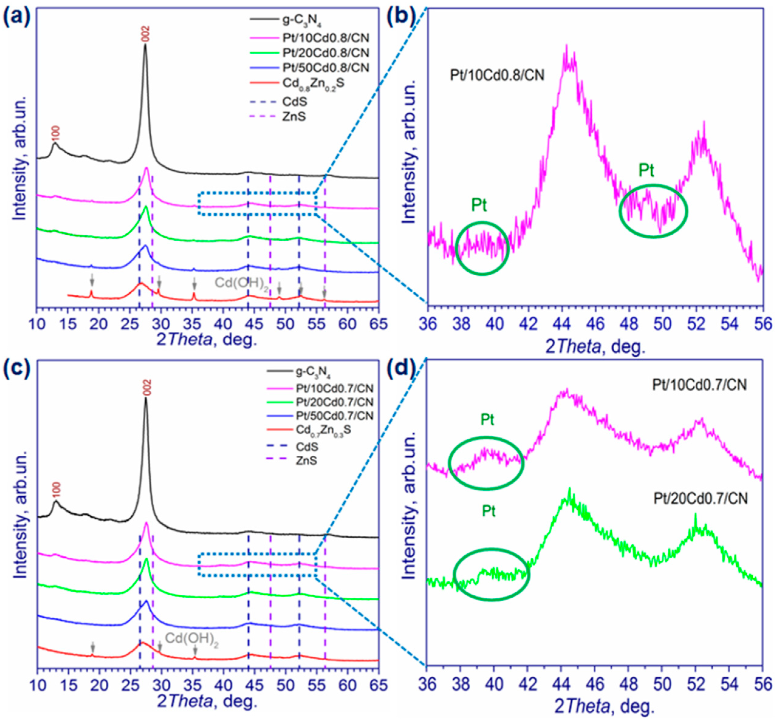
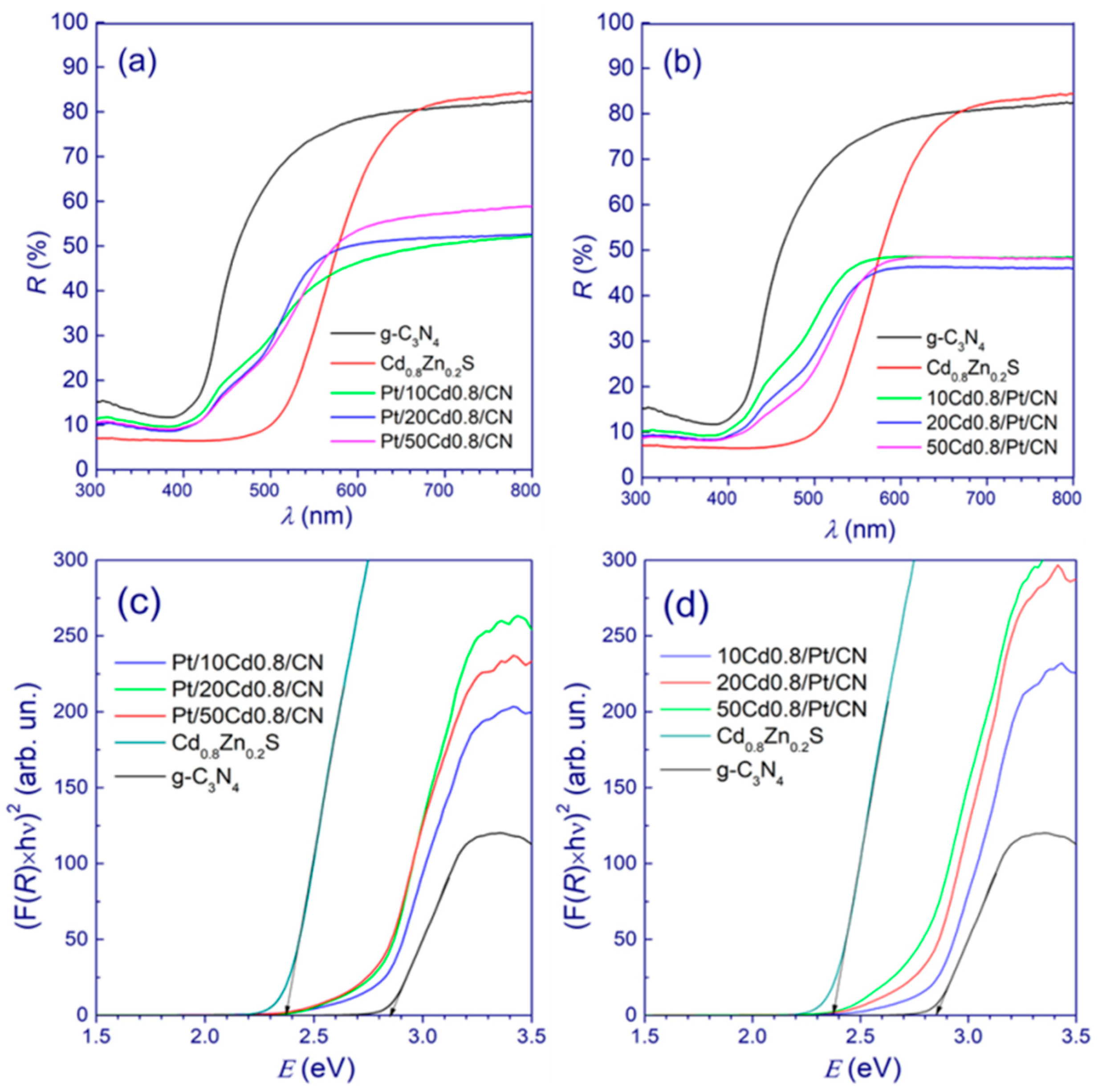
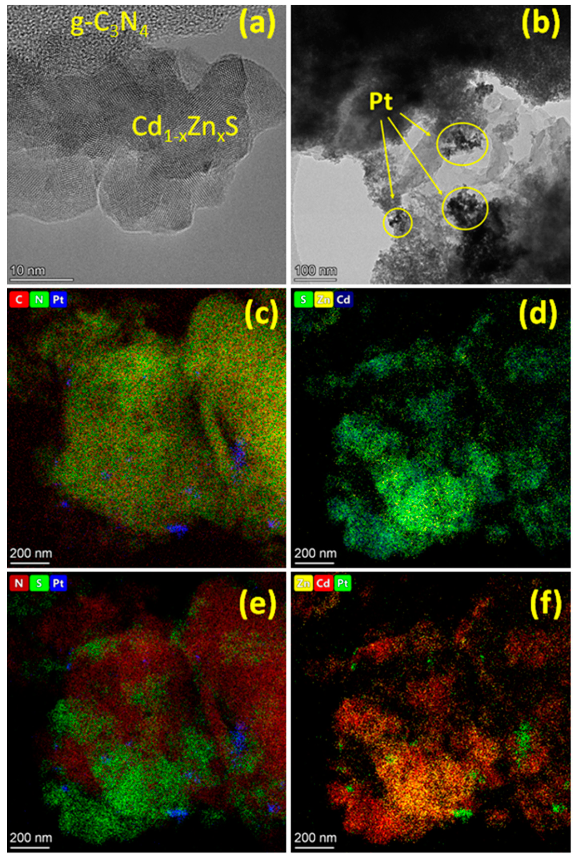
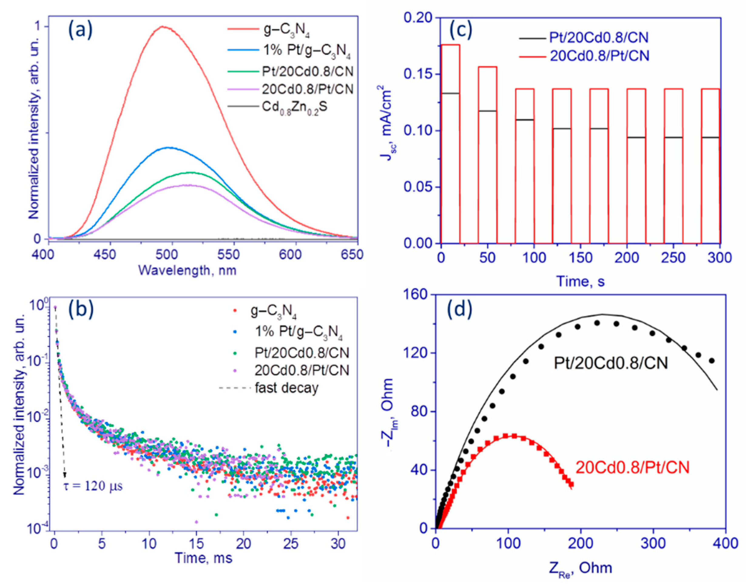
2.1. Characterization of Photocatalysts Based on Cd1−xZnxS/g-C3N4

We obtained two types of photocatalysts, 1%Pt/Cd1−xZnxS/g-C3N4 (x = 0.2–0.3) and Cd1−xZnxS/1%Pt/g-C3N4 (x = 0.2–0.3), by varying the deposition order of platinum and a solid solution of cadmium and zinc sulfides onto the surface of g-C3N4. For Scheme 1 (Table 1), first, Cd1−xZnxS was deposited on the surface of g-C3N4, followed by metal deposition on the composite surface. In the case of Scheme 2 (Table 1), Cd1−xZnxS was deposited on the surface of pre-platinized Pt/g-C3N4. The abbreviation and properties of all synthesized samples are listed in Table 1; the X-ray diffraction patterns of the photocatalysts are shown in Figure 1.
The pristine g-C3N4 had clear diffraction peaks at 13.0° and 27.5°, which corresponded to the (100) and (002) planes of graphitic carbon nitride [39,40]. The first peak was attributed to in-plane repeated units of tri-s-triazine, whereas the second was related to the interlayer packing of g-C3N4 with the (002) diffraction plane [5]. Pristine Cd0.8Zn0.2S (Figure 1a) and Cd0.7Zn0.3S (Figure 1c) had three broad diffraction peaks located at 26.8–27.0°, 44.2–44.4°, and 50.0–52.3°, which corresponded to the (111), (220), and (311) planes, respectively, of the Cd1−xZnxS (x = 0.2–0.3) solid solutions with a cubic structure. Impure Cd(OH)2 peaks were also observed for the samples with Cd0.8Zn0.2S and Cd0.7Zn0.3S. The XRD patterns of composite photocatalysts Cd0.8Zn0.2S/g-C3N4 and Cd0.7Zn0.3S/g-C3N4 contained diffraction peaks of both g-C3N4 and Cd1−xZnxS solid solutions. The relative intensity of the (002) peak decreased with the increase in solid solution content. In the ternary composites (Pt/Cd0.8/CN and Pt/Cd0.7/CN), very low peaks of platinum were observed at 2Θ = 40° and ca. 46°, and average particle size ca. 2 nm. The average crystallite sizes of g-C3N4 calculated from diffraction peaks (100) and (002) were 11.7 nm in the plane of the layers and 19.8 nm in the direction perpendicular to the layers, respectively, for all samples and did not change after the deposition of Cd1−xZnxS. The average crystalline size values for Cd1−xZnxS varied within 7.4–9.6 nm (x = 0.2) and 5.1–8.5 nm (x = 0.3). The crystalline size grew with the increase in the amount of the corresponding solid solution of CdS and ZnS; for pristine Cd0.8Zn0.2S and Cd0.7Zn0.3S, these values were 7.3 and 5.7 nm, respectively. The deposition order of the photocatalyst component was not significantly implied by the XRD patterns and values of average crystallite size.
The textural properties of the photocatalysts were also investigated (Table 2). The specific surface area of pristine Cd0.8Zn0.2S was equal to 177 m2 g−1, whereas the surface area of g-C3N4 did not exceed 20 m2 g−1. The formation of the hybrid composite structure led to an intermediate specific surface area from 34 to 68 m2 g−1, wherein the surface increased with the content of the Cd0.8Zn0.2S solid solution in the composite.
UV–visible spectra of the g-C3N4, Cd0.8Zn0.2S photocatalysts, and ternary composites were obtained, and the result is shown in Figure 2a,b. The spectra of the composite samples lay between the UV–vis spectra of the g-C3N4 and Cd0.8Zn0.2S samples. Platinum nanoparticles also decreased reflectance in the range of 500–800 nm. The absorption edges of the composite samples and Cd0.8Zn0.2S were estimated using the Tauc function for semiconductors with direct transitions, F(R)2(hν)2 (Figure 2c,d). For g-C3N4, the band gap was 2.85 eV (absorption edge was 435 nm); for Cd0.8Zn0.2S, the band gap was 2.37 eV (absorption edge was 523 nm); and the adsorption edges of the composite ternary samples had intermediate values (Table 2). The absorption edges of two series of photocatalysts, Pt/Cd0.8/CN (Scheme 1) and Cd0.8/Pt/CN (Scheme 2), were close to each other, and the spectra had no remarkable differences. Altogether, all prepared samples absorbed visible light and could be used as active photocatalysts for hydrogen photoproduction.
The XPS method was used to study the Pt/20Cd0.8/CN and 20Cd0.8/Pt/CN samples prepared according to Schemes 1 and 2, respectively (Figure 3). The survey spectra showed the presence of C, S, N, and Pt elements on the surface of ternary composites. Figure 3a shows that C1s had two peaks with binding energies of 284.8 and 288.1 eV corresponding to the C–C and N–C=N bonds in g-C3N4, respectively [41]. The first peak may be attributed to the adventitious carbon [42]. For the 20Cd0.8/Pt/CN sample, the peak corresponding to the C–C bond was higher than that for Pt/20Cd0.8/CN, and the peak corresponding to the N–C=N bond was lower. The N1s XPS peak (Figure 3b) could be divided into three peaks located at 404.9, 400.0, and 398.9 eV. The main peak at 398.9 eV came from sp2-bonded nitrogen, which was included in the triazine rings C=N–C of g-C3N4, the peak at 400.4 eV was related to the N–(C)3 bond, and the peak at 404.9 eV was probably linked to the C–N–H bond [43]. The S2p peaks (Figure 3c) around 161.4 indicate that the state of sulfur is S2− [44]. Sulfur is partially oxidized in air to SO32− or SO42−, confirmed by the peak at 168.0 eV [45]. The content of oxidized forms of sulfur was quite low for both samples. The Pt4f peaks at 71.1 and 72.5 eV correspond to two states of platinum, Pt0 and Pt2+ (Figure 3d) [46,47].
Table 3 represents the surface ratios of elements calculated using the XPS technique. The main difference is the surface content of platinum. In the case of Scheme 1, when platinum was deposited onto the surface of the Cd0.8Zn0.2S/g-C3N4 composite, the surface ratio [Pt]/[Cd + Zn] was six times higher than that in the case of platinum deposition onto the surface of g-C3N4 nitride, followed by sulfide solid solution deposition (Scheme 2), at the same Pt loading, 1 wt. %, which looked quite logical from the synthesis technique, because in the case of Scheme 2, a solid solution of cadmium and zinc sulfides is deposited over the platinum located on the surface of g-C3N4, which can reduce the surface concentration of platinum. Additionally, later in the text, it will be shown by the TEM method that in the case of Scheme 1, smaller platinum particles are formed. For the 20Cd0.8/Pt/CN sample, Pt existed only in metallic form, while Pt0 and Pt2+ were identified for Pt/20Cd0.8/CN. For the sample prepared according to Scheme 2, 20Cd0.8/Pt/CN, the percentage of sulfur in the form of sulfide was higher at 92% compared to 84% in the case of photocatalyst Pt/20Cd0.8/CN. For Pt/Cd1−xZnxS photocatalysts, platinum in metallic state and sulfur in S2− state are preferable for photocatalytic hydrogen production [48].
The composition of the Pt/20Cd0.8/CN photocatalyst (Scheme 1) was studied with the HAADF-STEM method with EDX elemental mapping. Figure 4 confirms the presence of Cd, Zn, Pt, C, N, and S in the tested sample. Figure 4a,f demonstrate the formation of C3N4 material, whereas Figure 4b–d reveal the presence of the Cd1−xZnxS phase. It was important to define the location of Pt nanoparticles in the sample. The comparison of Figure 4b–d proves the platinization of the Cd1−xZnxS phase only because no platinum signal was observed in the absence of Cd, S, and Zn. Figure 4g–i show that Pt nanoparticles were uniformly distributed on the surface of the solid solution; Pt particle size did not exceed 2 nm.
The 20Cd0.8/Pt/CN sample was studied by the HRTEM method. Figure 5a demonstrates the formation of two particle types in the samples. The first was connected with the layer structure identifying g-C3N4. The domains with regular structure and sizes at about 10–15 nm may be attributed to the solid solution of CdS and ZnS. The particle sizes were slightly higher than the calculated average crystallite sizes. Therefore, the XRD and HRTEM data coincided with each other. Figure 5a also demonstrates good interphase contact between Cd1−xZnxS and C3N4 and confirms the possibility of heterojunction formation. The 20Cd0.8/Pt/CN photocatalyst was also investigated by the HAADF-STEM method with EDX elemental mapping. Figure 5c–f show the elemental distribution in the 20Cd0.8/Pt/CN sample. Figure 5e,f define the location of the Pt cocatalyst: large elongated clusters of platinum particles were located over the surface of g-C3N4; the length of some clusters particles reached 100 nm. The platinum clusters are shown in Figure 5b; one can see that these clusters consisted of Pt nanoparticles with a size of 2–5 nm. The formation of clusters can be explained by the inhomogeneity of the surface of layered graphitic carbon nitride, on which the platinum particles were deposited. It has recently been shown that this kind of noble metal cluster can be an effective cocatalyst for the photocatalytic process [49]. To elucidate the location of the platinum, we summarized the EDX local analysis data in Tables S1–S4 (Supplementary Materials). EDX data confirm that platinum nanoparticles with a high concentration (1.3–1.7 at. %) are localized in domains with a dominant content of g-C3N4. For areas where both sulfide and nitride are found, the platinum concentration does not exceed 0.2 at. %.
TEM analysis suggests that the Pt/20Cd0.8/CN (Scheme 1) and 20Cd0.8/Pt/CN (Scheme 2) photocatalysts had fundamentally different structures: in the first case, small platinum particles were deposited onto a surface of the solid solution of cadmium and zinc sulfides in the Cd0.8Zn0.2S/g-C3N4 composite; in the latter case, enlarged platinum clusters were located on the surface of graphitic carbon nitride. A similar structure was also confirmed by XPS data, since in the second case, the surface content of platinum was much lower. In addition, according to XPS data, in the first case, platinum was present in oxidation states Pt0 and Pt2+, while in the latter, it was only metallic state Pt0.

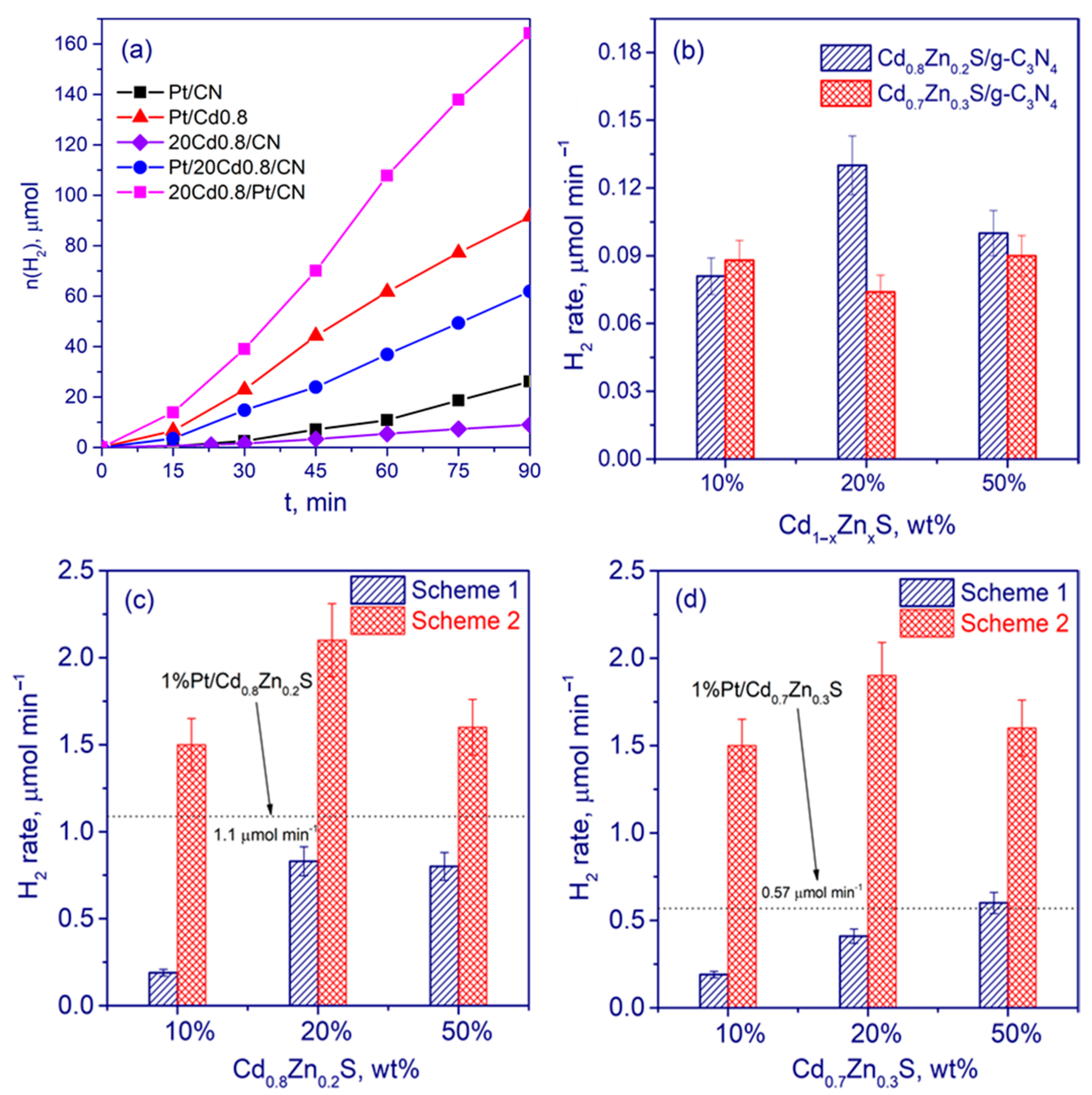
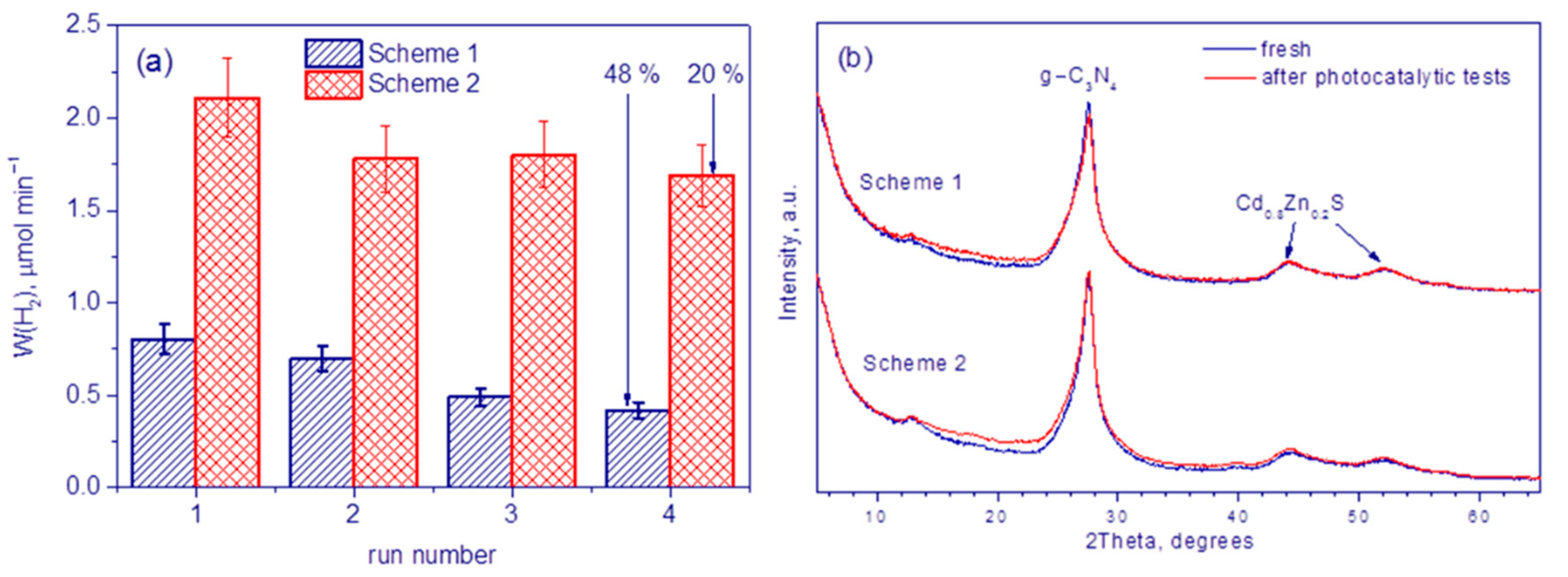
2.2. Photocatalytic Tests

Photocatalytic hydrogen evolution from aqueous solutions of TEOA was investigated under visible light irradiation (λ = 450 nm). To facilitate the proton abstraction during the chain process of TEOA oxidation and therefore to prevent charge recombination the reaction was carried out in an 0.1 M NaOH aqueous solution [50]. The kinetics of hydrogen evolution over the selected photocatalysts is shown in Figure 6a. For pristine g-C3N4, Cd0.8Zn0.2S, and Cd0.7Zn0.3S, the hydrogen evolution rate was close to zero. The rates of hydrogen production over samples 10–50 Cd0.8/CN and 10–50 Cd0.7/CN are shown in Figure 6b. For the photocatalysts without platinum, the rate of hydrogen formation did not exceed 0.13 μmol hydrogen per minute. Considering that the rates of hydrogen production in the presence of g-C3N4, or Cd0.8Zn0.2S and Cd0.7Zn0.3S solid solutions were close to zero, the creation of composite samples led to a remarkable increase in activity in comparison to the pristine compounds, confirming the appearance of interphase heterojunctions between g-C3N4 and Cd1−xZnxS.
Platinum deposition on the surface of composite samples Cd1−xZnxS/g-C3N4, g-C3N4, and Cd1−xZnxS (x = 0.2–0.3) solid solutions led to a significant increase in activity. However, for photocatalysts prepared according to Scheme 1, when platinum was allocated onto the surface of solid solutions of cadmium and zinc sulfides (Pt/10–50 Cd0.8/CN and Pt/10–50 Cd0.7/CN), the activity of the ternary composite samples did not exceed the activity of platinized single-phase sulfides, such as 1% Pt/Cd0.8Zn0.2S and 1% Pt/Cd0.7Zn0.3S. This can be explained by the specific surface area of the samples: for Cd0.8Zn0.2S and Cd0.7Zn0.3S solid solutions, the specific surface area was ca. 180 m2 g−1; for g-C3N4, it was about 20 m2 g−1; and for composite samples Pt/10-50 Cd0.8/CN, this value varied from 34 to 67 m2 g−1 (Figure 6c,d). The positive effect due to the formation of heterojunctions between Cd0.8Zn0.2S and g-C3N4 did not compensate for the significant loss of specific surface area. In contrast, a noticeable increase in activity, approximately twofold, compared with the PtCd0.8 and Pt/Cd0.7 samples, was observed for photocatalysts prepared according to Scheme 2 (10–50 Cd0.8/Pt/CN and 10–50 Cd0.7/Pt/CN), for which large, elongated clusters of platinum particles were located at the interface between the Cd1−xZnxS and g-C3N4 phases. The highest activity at the level of 2500 μmol hydrogen per gram of photocatalyst per hour (2.1 μmol min−1) with an apparent quantum efficiency equal to 6.0% at a wavelength of 450 nm was possessed by sample 20% Cd0.8Zn0.2S/1% Pt/g-C3N4 (20 Cd0.8/Pt/CN). This value is comparable with previously published results, as shown in Table 4.
Thus, photocatalysts that are practically identical in chemical composition exhibit quite different activity in the process of photocatalytic production of hydrogen because of the different locations and shapes of the platinum nanoparticles for Pt/20Cd0.8/CN and 20 Cd0.8/Pt/CN samples. We built an energy diagram (Figure 7) for the g-C3N4/Cd0.8Zn0.2S system. It was calculated from UV–vis spectroscopy data (Figure 2) that the band gap was 2.8 eV for g-C3N4 and 2.4 eV for Cd0.8Zn0.2S. According to the literature data, the CB and VB potentials of g-C3N4 were −1.1 and + 1.7 V vs. NHE, respectively [4,22]; for the Cd0.8Zn0.2S solid solution, CB potential was equal to −0.4 V vs. NHE, and VB level equaled +2.0 V vs. NHE [63] (Figure 7). Thus, CB level was more negative for g-C3N4, and VB level was more positive for the sulfide solid solution.
As was discussed above, there are three possible mechanisms for the spatial separation of photogenerated charge carriers in the g-C3N4/Cd1−xZnxS system: conventional type II heterojunctions, Z-scheme, and S-scheme. However, the Z-scheme photocatalyst is now considered to be misleading by the scientific community [32]. All-solid-state Z-scheme with platinum as a mediator has large restrictions, because if platinum nanoparticles are located between two semiconductors, band bending arises at their interfaces, forming a Schottky barrier, and this Schottky barrier will suppress the electron flow from semiconductors to metal [36]. Additionally, as was shown in this study by TEM with EDX, in the case of both Scheme 1 (Pt/20Cd0.8/CN) and Scheme 2 (20 Cd0.8/Pt/CN), platinum is deposited onto individual semiconductors, Cd1−xZnxS or g-C3N4, respectively. Thus, we will further discuss the type II heterojunction and S-scheme, and metallic platinum will only be considered as a cocatalyst for the formation of hydrogen.
For photocatalysts synthesized according to Scheme 1, when Cd0.8Zn0.2S particles were deposited on the surface of g-C3N4 and Pt nanoparticles were, in turn, deposited onto the surface of the sulfide solid solution, the formation of hydrogen is most likely localized over sulfide particles, because it is there that the cocatalyst is deposited. The photogenerated electrons likely moved from the CB of g-C3N4 to the CB of Cd0.8Zn0.2S and then to platinum particles, whereas holes from the VB of sulfide solid solution migrated to the VB of g-C3N4 (Figure 7a). Thus, in the case of photocatalyst Pt/20Cd0.8/CN, conventional type II heterojunctions were likely realized. This type of heterojunction has been described for Pt/CdS/g-C3N4 systems with platinum deposited on CdS nanoparticles [22,23,24]. Unfortunately, for all samples synthesized according to Scheme 1, no increase in activity in comparison to Pt/Cd1−xZnxS was observed. The obtained results can be explained as follows: when type II heterojunctions appeared in the Cd1−xZnxS/g-C3N4 system, the spatial separation of photogenerated electrons and holes was observed; however, the electrons and holes were accumulated in the CB of Cd1−xZnxS and the VB of g-C3N4, which possess low reduction and oxidation potentials, respectively [64]. This explains the decrease in photocatalyst activity in the hydrogen evolution from aqueous solutions of TEOA.
For the 20Cd0.8/Pt/CN photocatalyst (Scheme 2), large, elongated clusters of platinum particles were located on the surface of the g-C3N4 phase (Figure 7b). In this case, it is logical to assume that the formation of hydrogen occurs over the g-C3N4 surface. The activity of the 20Cd0.8/Pt/CN photocatalyst was much higher than that of the Pt/20 Cd0.8/CN photocatalyst. Moreover, this pattern remained unchanged for all 10–50% Cd1−xZnxS/g-C3N4 (x = 0.2–0.3) photocatalysts with 1 wt. % platinum. Additionally, the activity of Scheme 2 composites is much higher than the activity of single-phase platinized 1%Pt/Cd1−xZnxS (x = 0.2–0.3) or 1%Pt/g-C3N4. It can be assumed that the formation of heterojunctions according to the S-scheme, when electrons remain in CB of g-C3N4 (Figure 7b), whereas electrons from CB of Cd1−xZnxS and holes from VB of g-C3N4 recombine, occurs first, and then molecular hydrogen is formed on the platinum cocatalyst particle. This implementation of the process leads to the highest activities in hydrogen production. Additionally, platinum in metallic state and sulfur in S2− state, as was shown by XPS for 20Cd0.8/Pt/CN, can lead to enhanced activity of the Scheme II photocatalysts.
The charge-transfer mechanism in an S-scheme heterojunction can be explained as follows. When Cd0.8Zn0.2S and g-C3N4 are in intimate contact, electrons from CB of g-C3N4 diffuse to CB of Cd0.8Zn0.2S, creating an electron depletion layer and an electron accumulation layer near the interface of g-C3N4 and Cd0.8Zn0.2S, respectively. Thus, an internal electric field directing from g-C3N4 to Cd0.8Zn0.2S occurs. This internal electric field accelerates the electrons transfer from Cd0.8Zn0.2S to g-C3N4, and hole transfer from g-C3N4 to Cd0.8Zn0.2S as shown in Figure 7b. Additionally, the band bending urges the photogenerated electrons from the CB of Cd0.8Zn0.2S and holes from the VB of g-C3N4 at the interface region. Thus, the photogenerated electrons in the CB of Cd0.8Zn0.2S and holes in the VB of g-C3N4 recombine at the interface under the Coulombic attraction [32].
Thus, on the basis of the above band structure analysis, TEM and XPS analysis of the samples, and enhanced H2 evolution activity, the formation of S-scheme heterojunctions is more favorable than the type II heterojunction between the Cd1−xZnxS and g-C3N4 semiconductors. Note that the synthesis of Cd1−xZnxS/g-C3N4 with different locations of platinum particles was conducted for the first time.
Figure 8a presents the normalized PL spectra of C3N4, 1% Pt/C3N4, Pt/20Cd0.8/CN, 20Cd0.8/Pt/CN, and Cd0.8Zn0.2S. The g-C3N4 photocatalyst demonstrated the most intensive photoluminescence; for Cd0.8Zn0.2S, photoluminescence was not observed. The obtained spectra for C3N4 and 1% Pt/C3N4 were similar in shape but different in intensity. Upon photoexcitation at 380 nm, the emission was centered at 490 nm and may be attributed to n–π* electronic transitions consisting of lone pairs of N atoms in graphitic carbon nitride [65]. The deposition of Pt onto the surface g-C3N4 photocatalyst led to a decrease in the intensity, at 2.3, which indicated a lower recombination rate of electron-hole pairs in the Pt-containing photocatalyst. The photoluminescence of the ternary composites was also studied. Figure 8a shows that the spectra of Pt/20Cd0.8/CN and 20Cd0.8/Pt/CN were identical in shape; the peak center was at 515 nm. The maximal intensities of Pt/20Cd0.8/CN and 20Cd0.8/Pt/CN were 3.1 and 4 times less than that of g-C3N4, respectively. Therefore, the efficiencies of radiative processes in the ternary composites were smaller; these samples can possess higher photocatalytic activity. The photocatalyst prepared according to Scheme 2 also exhibited the lowest photoluminescence intensity.
Figure 8b shows the decay curves of the PL intensities of the g-C3N4-based photocatalysts. All curves were almost identical. Numerical analysis showed that PL intensity decreased by a factor of 100 during 3 ms after the start of measurements. In this case, decay kinetics was nonexponential and could not be represented as a superposition of two or three exponential processes. If we assumed a fast decay of the first-order kinetics, the lifetime of such processes is τ = 120 ± 15 μs (see the dashed line in Figure 8b). The nature of the observed behavior in the studied interval of time may be due to the phosphorescent mechanism under the used excitation and the presence of trapping centers of separated charge carriers, which favored photocatalytic hydrogen production.
The photoelectrochemical properties of the samples Pt/20Cd0.8/CN and 20Cd0.8/Pt/CN were tested. Figure 8c shows that both photocatalysts possess typical photocurrent responses during on-off experiments. The photocurrent intensity is slightly higher for the 20Cd0.8/Pt/CN synthesized according to Scheme 2, which indicates more efficient charge separation for this photocatalyst [66]. Additionally, EIS spectra were obtained for these two samples (Figure 8d). Compared with Pt/20Cd0.8/CN photocatalyst, the Nyquist plots of 20Cd0.8/Pt/CN sample exhibit a significantly smaller impedance arc radius. Thus, the electrochemical experiments confirm that construction of the structure of 20Cd0.8/Pt/CN photocatalyst with platinum deposited over g-C3N4 surface improves the interface charge separation.
An important aspect of the study of photocatalysts is the investigation of their stability. We tested the activity of the Pt/20Cd0.8/CN and 20Cd0.8/Pt/CN photocatalysts in four consecutive hydrogen evolution runs (Figure 9a). Photocatalyst 20Cd0.8/Pt/CN had greater stability than that of photocatalyst Pt/20Cd0.8/CN. We characterized samples after the hydrogen evolution by the XPS and XRD techniques (Table 3, Figure 9b). Figure 10 shows that the bulk structure of the samples does not undergo any changes. However, according to XPS data (Table 3) after hydrogen evolution, the following changes took place on the photocatalyst surface:
-
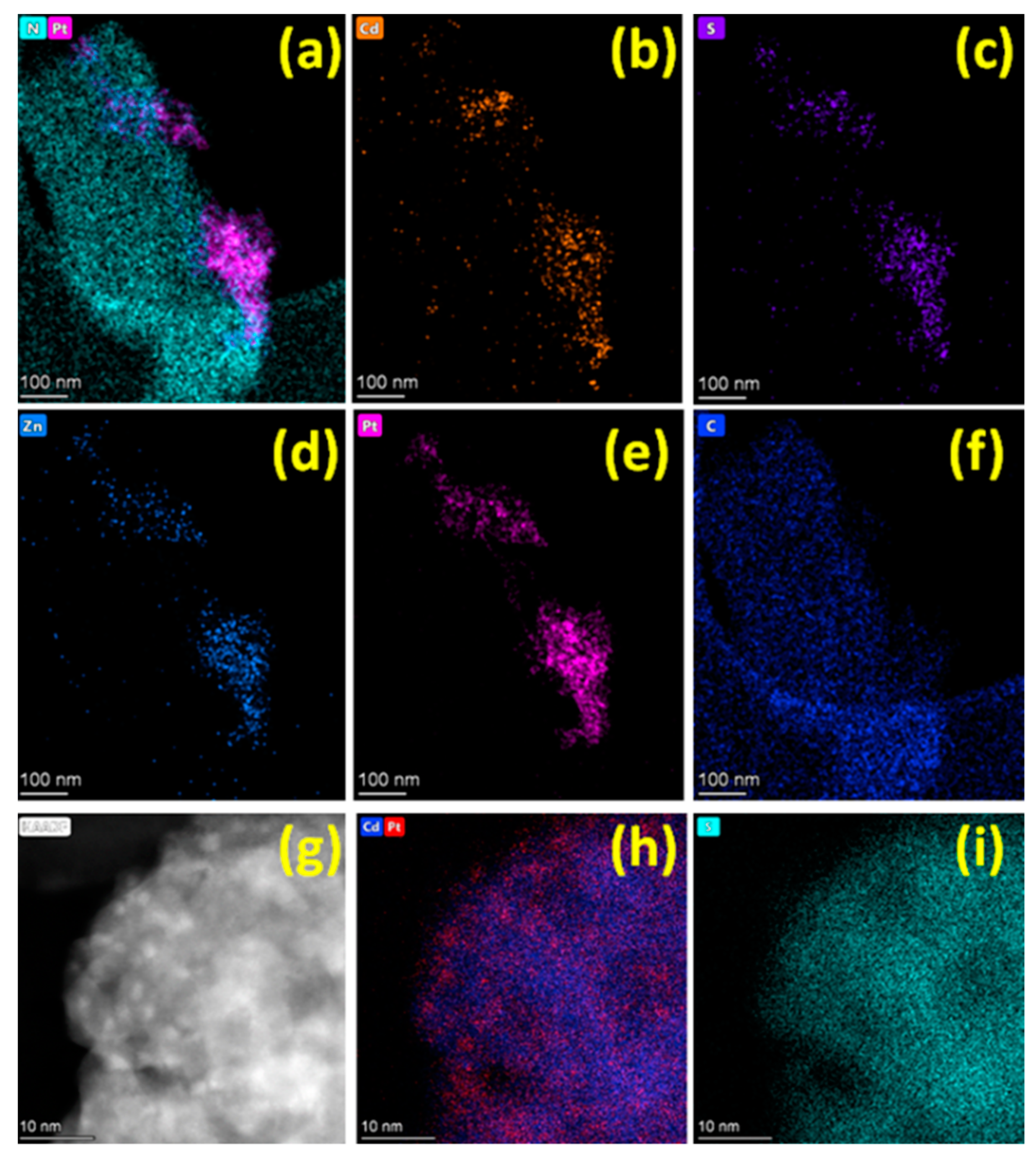
Surface ratio [Cd + Zn]/[C] and [S]/[C] decreased for both photocatalysts indicating the aggregation of Cd1−xZnxS particles; for sample 20Cd0.8/Pt/CN, it was to a lesser extent;
-
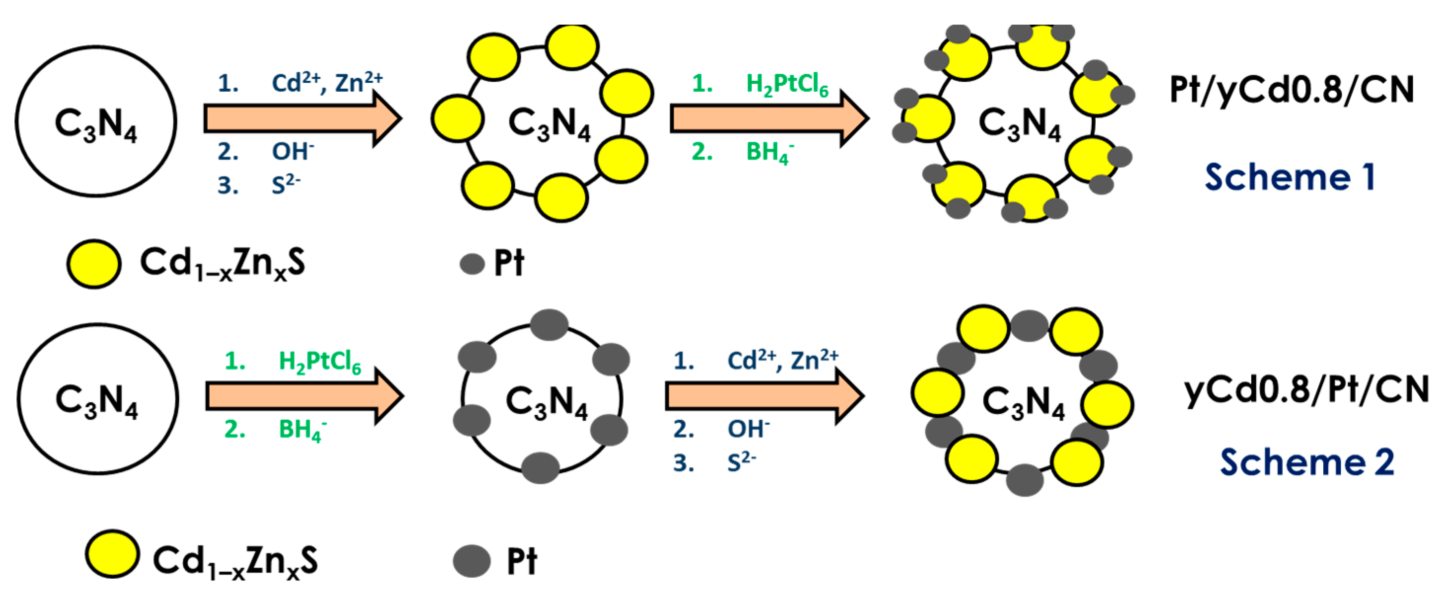
The [Pt]/[C] surface ratio decreased slightly for the Pt/20Cd0.8/CN sample, but this ratio increased threefold for the 20Cd0.8/Pt/CN photocatalysts. This suggests that, in the first case, the metal particles were enlarged, and in the latter, they were dispersed. Please note that the ratio of [S]/[C] and [Cd + Zn]/[C] became smaller and simultaneously ratio of [Pt]/[Cd + Zn] became bigger for both samples, that is, the particles of the solid solution of sulfide aggregated, and the size of the platinum particles either practically did not grow (Pt/20Cd0.8/CN), or became smaller (20Cd0.8/Pt/CN).
-
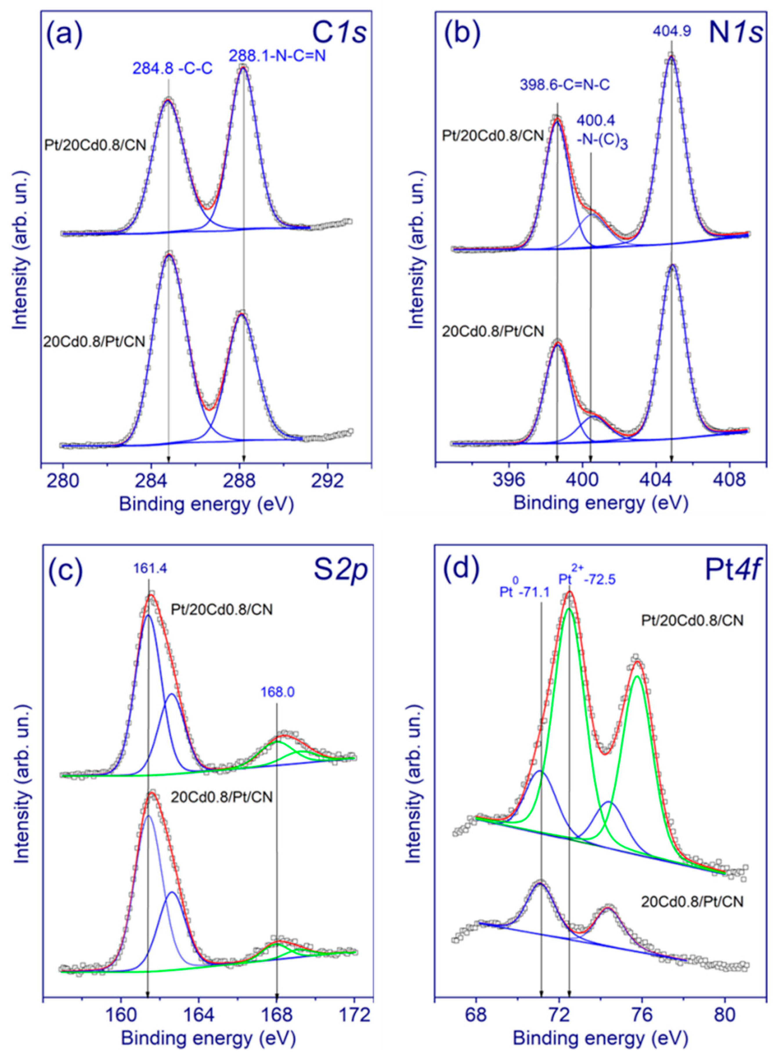
Sulfur in the sulfite/sulfate state on the surface completely transformed into sulfide S2− for both samples;
-
An increase in the proportion of platinum in zero oxidation state was seen for sample Pt/20Cd0.8/CN; for sample 20Cd0.8/Pt/CN, metallic platinum partially transformed into Pt2+.
Among these factors, the reduction of Pt2+ into metallic platinum, the reduction of SOx2− anions into S2−, and a decrease in the size of platinum particles had a positive effect on the rate of hydrogen evolution. Regarding the aggregation of both platinum and Cd1−xZnxS solid solution particles, this led to photocatalyst deactivation. Based on these competing factors, the stability of the photocatalyst prepared according to Scheme 2 was much better than the stability of the photocatalyst prepared according to Scheme 1. Thus, the use of synthetic Scheme 2 makes it possible to obtain both active and stable photocatalysts Cd1−xZnxS/Pt/g-C3N4.

3. Materials and Methods

3.1. Photocatalyst Synthesis

3.1.1. Synthesis of g-C3N4

Melamine was chosen as a precursor. Usually, 2 g of the precursor was annealed in a ceramic crucible with a lid at 600 °C with a heating rate of 5 °C/min for 2 h [8]. The obtained g-C3N4 was ground in a mortar to a yellow powder. Platinum (1 wt. %) was deposited on the surface prepared photocatalysts by impregnation with hexachloroplatinic acid followed by reduction with a 2.5-fold excess of sodium borohydride. This method was described in detail earlier [38]. Samples were dried at 50 °C for 4 h after decantation several times.

3.1.2. Synthesis of Photocatalysts Based on Cd1−xZnxS/g-C3N4

To prepare the samples Cd0.7Zn0.3S/g-C3N4 and Cd0.8Zn0.2S/g-C3N4 with a certain percentage of Cd1−xZnxS (10, 20, and 50%), a proper amount of 0.1 M cadmium chloride and 0.1 M zinc nitrate were added to the suspension of g-C3N4 (Scheme 1) or 1%Pt/g-C3N4 (Scheme 2), and then the total volume of 0.1 M NaOH equal to the sum of zinc and cadmium chloride volumes was added, and the mixture was stirred for 20 min. Then, a solution of 0.1 M Na2S with a volume 2.5 times higher than the volume of NaOH was added, and the mixture was stirred for 60 min. The obtained suspension was placed in Teflon beakers, centrifuged, and the precipitate was washed with distilled water. Then the precipitate was decanted and dried for 4 h at 80 °C. The dried sample was ground in a mortar. In the case of Scheme 1, 1 wt. % Pt was deposited on the prepared Cd1−xZnxS/g-C3N4 samples by the impregnation method as described above. The composition and the abbreviations of the samples are given in Table 1, the scheme of the synthesis is represented in Figure 10.

3.2. Photocatalysts Characterization

The photocatalysts were characterized by UV–vis optical absorption and luminescence spectroscopy, X-ray diffraction (XRD), X-ray photoelectron spectroscopy (XPS), high-resolution transmission electron microscopy (HRTEM), including the high-angle annular dark-field scanning transmission electron microscopy (HAADF-STEM) technique, N2 low-temperature adsorption.
The diffuse reflectance UV–vis spectra were obtained using a Shimadzu UV-2501 PC spectrophotometer with an ISR-240A diffuse reflectance unit. XRD patterns were recorded using a Bruker D8 Advance diffractometer in the 2θ range 10° to 80° using the Cu Kα radiation. The mean sizes of crystallites were estimated from the full width at half maximum of corresponding peaks using the Scherrer formula. The specific surface areas of the photocatalysts were obtained from the low-temperature N2 adsorption–desorption (N2 adsorption at 77 K) using an ASAP 2400 apparatus.
X-ray photoelectron spectra were measured on a SPECS (Germany) photoelectron spectrometer using a hemispherical PHOIBOS-150-MCD-9 analyzer and FOCUS-500 (Al Kα radiation, hν = 1486.74 eV, 200 W) monochromator. The binding energy (BE) scale was pre-calibrated using the positions of the peaks of Au4f7/2 (BE = 84.0 eV) and Cu2p3/2 (BE = 932.67 eV) core levels. The samples were loaded onto a conducting double-sided copper scotch. The binding energy of peaks was calibrated by the position of the C1s peak (BE = 284.8 eV) corresponding to the surface hydrocarbon-like deposits (C–C and C–H bonds).
The structure and microstructure of the photocatalysts were studied by HRTEM using a ThemisZ electron microscope (Thermo Fisher Scientific, Waltham, MA, USA) operated at an accelerating voltage of 200 kV. The microscope was equipped with a corrector of spherical aberrations, which provided a maximum lattice resolution of 0.06 nm, and a SuperX spectrometer (TFS, Waltham, MA, USA). Images were recorded using a Ceta 16 CCD sensor (Thermo Fisher Scientific, Waltham, MA, USA). For electron microscopy studies, samples were deposited on perforated carbon substrates attached to aluminum grids using an ultrasonic dispersant.
Spectral and kinetic photoluminescent (PL) curves in a millisecond time window were measured on a Perkin Elmer LS55 spectrometer at room temperature. The spectral widths of the slits in the exciting and recording channels were 10 and 20 nm, respectively. PL spectra were recorded in the range 400–650 nm with excitation in the 380 nm band and a scan rate of 60 nm min−1. The experimental spectra were normalized to the maximum PL intensity in the g-C3N4 sample. The kinetics of PL decay was recorded in the 490 nm band upon excitation in the 380 nm band. The kinetic dependences were normalized to the maximum value of the PL intensity in each sample.

3.3. Photocatalytic Activity Measurement

The synthesized catalysts were studied in photocatalytic hydrogen evolution from aqueous alkaline triethanolamine (TEOA) solutions [8]. Usually, 50 mg of the photocatalyst was suspended in a solution that contained 10 mL of triethanolamine and 90 mL of 0.11 M NaOH. Then, the suspension was purged with argon for 30 min and illuminated with a 450-LED. The amount of evolved hydrogen was measured on a Khromos GKh-1000 gas chromatograph (Khromos, Omsk, Russia) equipped with a zeolite column and a thermal conductivity detector. Argon was used as a carrier gas. The photocatalytic activity of the samples was estimated as the hydrogen evolution rate (µmol min−1). The apparent quantum efficiency (AQE) was calculated by the following formula:
A Q E = W N p h × 100 % ,
where W—reaction rate (µmol min−1), Nph—photon flux (µEinstein min−1). For all experiments, Nph = 34 µEinstein min−1.

3.4. Photoelectrochemical Experiments

Photoelectrochemical experiments were conducted using a two-electrode cell. The working electrode was FTO with the photocatalyst deposited by the drop-casting method. The counter electrode was Cu2S/brass, the electrolyte was a solution consisting of 1 M Na2Sn and 0.1 M NaCl. Photoelectrochemical characteristics were obtained using a potentiostat–galvanostat P-45X (Electrochemical Instruments, Chernogolovka, Russia). The current–time curves were registered at 0 V. The impedance data were recorded over a frequency range of 0.8 to 105 Hz with an amplitude of 10 mV at 0.2 V. The light source was 450-LED, which was used for the photocatalytic tests. ×

4. Conclusions

In this work, a new technique for constructing efficient Cd1−xZnxS/Pt/g-C3N4 heterojunctions was proposed. Two groups of ternary photocatalysts based on platinized 10–50 wt. % Cd1−xZnxS/g-C3N4 (x = 0.2–0.3) were synthesized. It was shown for the first time that, by changing the order of platinum deposition, one can obtain two types of photocatalysts, Pt/Cd1−xZnxS/g-C3N4 and Cd1−xZnxS/Pt/g-C3N4, with a different structure: in the first case, small platinum particles are deposited onto the surface of the solid solution of cadmium and zinc sulfides; in the latter case, enlarged platinum clusters are located over the surface of graphitic carbon nitride.
The rate of photocatalytic hydrogen production under visible light was much higher in the case of using photocatalysts of the second type, Cd1−xZnxS/1 wt. % Pt/g-C3N4, in comparison to photocatalysts of the first type, 1 wt. % Pt/Cd1−xZnxS/g-C3N4 with a similar bulk structure of Cd1−xZnxS and g-C3N4 and equal mass fractions of components. Analysis of the band-gap structure of ternary samples, and TEM and XPS analyses showed that, for more active photocatalysts, the mechanism of interphase heterojunctions according to the S-scheme is most likely realized, while photocatalysts with low activity are characterized by type II heterojunctions. Moreover, S-scheme photocatalysts have greater stability than type II heterojunction photocatalysts do. The highest activity, 2.5 mmol H2 g−1 h−1, with an apparent quantum efficiency equal to 6.0% at a wavelength of 450 nm was performed by sample 20% Cd0.8Zn0.2S/1% Pt/g-C3N4. The synthesis of Cd1−xZnxS/g-C3N4 with different locations of platinum particles and the assessment of their photocatalytic properties was carried out for the first time.

Supplementary Materials

The following are available online at https://0-www-mdpi-com.brum.beds.ac.uk/article/10.3390/catal11111340/s1, Table S1: EDX data of the photocatalyst 20Cd0.8/Pt/CN; domain with predominated g-C3N4 content; Table S2: EDX data of the photocatalyst 20Cd0.8/Pt/CN; domain with predominated g-C3N4 content; Table S3: EDX data of the photocatalyst 20Cd0.8/Pt/CN; domain with g-C3N4 and Cd0.8Zn0.2S; Table S4: EDX data of the photocatalyst 20Cd0.8/Pt/CN; domain with g-C3N4 and Cd0.8Zn0.2S.

Author Contributions

Conceptualization, A.V.Z.; validation, A.V.Z.; formal analysis, I.P.P., S.V.C. and A.V.B.; investigation, D.V.M., E.Y.G. and I.A.W.; data curation, D.V.M., A.S.V., I.P.P., S.V.C. and A.V.B.; writing—original draft preparation, A.V.Z., D.V.M. and E.A.K.; visualization, A.V.Z., D.V.M., E.Y.G. and A.S.V.; supervision, I.A.W. and E.A.K.; project administration, E.A.K.; funding acquisition, E.A.K. All authors have read and agreed to the published version of the manuscript.

Funding

This work was supported by the Ministry of Science and Higher Education of the Russian Federation within the governmental order for Boreskov Institute of Catalysis (project AAAA-A21-121011390009-1) and was also funded by the Russian Foundation for Basic Research (project No. 20-33-70086). A.S.V. and I.A.W. thank Minobrnauki research project FEUZ-2020-0059 for financial support.

Data Availability Statement

The data presented in this study are available on request from the corresponding author.

Acknowledgments

The authors are grateful to T.V. Larina for DRS analysis. The studies were conducted using the equipment of the Center of Collective Use “National Center of Catalyst Research”.

Conflicts of Interest

The authors declare no conflict of interest.

References

  1. Domen, K.; Hara, M.; Kondo, J.; Takata, T.; Kudo, A.; Kobayashi, H.; Inoue, Y. New aspects of heterogeneous photocatalysts for water decomposition. Korean J. Chem. Eng. 2001, 18, 862–866. [Google Scholar] [CrossRef]
  2. Fujishima, A.; Honda, K. Electrochemical Photolysis of Water at a Semiconductor Electrode. Nature 1972, 238, 37–38. [Google Scholar] [CrossRef] [PubMed]
  3. Wang, X.; Maeda, K.; Thomas, A.; Takanabe, K.; Xin, G.; Carlsson, J.M.; Domen, K.; Antonietti, M. A metal-free polymeric photocatalyst for hydrogen production from water under visible light. Nat. Mater. 2009, 8, 76–80. [Google Scholar] [CrossRef] [PubMed]
  4. Ye, S.; Wang, R.; Wu, M.-Z.; Yuan, Y.-P. A review on g-C3N4 for photocatalytic water splitting and CO2 reduction. Appl. Surf. Sci. 2015, 358, 15–27. [Google Scholar] [CrossRef]
  5. Madhusudan, P.; Shi, R.; Xiang, S.; Jin, M.; Chandrashekar, B.N.; Wang, J.; Wang, W.; Peng, O.; Amini, A.; Cheng, C. Construction of highly efficient Z-scheme ZnxCd1-xS/Au@g-C3N4 ternary heterojunction composite for visible-light-driven photocatalytic reduction of CO2 to solar fuel. Appl. Catal. B Environ. 2021, 282, 119600. [Google Scholar] [CrossRef]
  6. Safaei, J.; Mohamed, N.A.; Noh, M.F.M.; Soh, M.F.; Ludin, N.A.; Ibrahim, M.A.; Isahak, W.N.R.W.; Teridi, M.A.M. Graphitic carbon nitride (g-C3N4) electrodes for energy conversion and storage: A review on photoelectrochemical water splitting, solar cells and supercapacitors. J. Mater. Chem. A 2018, 6, 22346–22380. [Google Scholar] [CrossRef]
  7. Kumar, P.; Boukherroub, R.; Shankar, K. Sunlight-driven water-splitting using two-dimensional carbon based semiconductors. J. Mater. Chem. A 2018, 6, 12876–12931. [Google Scholar] [CrossRef]
  8. Zhurenok, A.V.; Larina, T.V.; Markovskaya, D.V.; Cherepanova, S.V.; Mel’Gunova, E.A.; Kozlova, E.A. Synthesis of graphitic carbon nitride-based photocatalysts for hydrogen evolution under visible light. Mendeleev Commun. 2021, 31, 157–159. [Google Scholar] [CrossRef]
  9. Kozlova, E.; Parmon, V.N. Heterogeneous semiconductor photocatalysts for hydrogen production from aqueous solutions of electron donors. Russ. Chem. Rev. 2017, 86, 870–906. [Google Scholar] [CrossRef]
  10. Ismail, A.A.; Bahnemann, D.W. Photochemical splitting of water for hydrogen production by photocatalysis: A review. Sol. Energy Mater. Sol. Cells 2014, 128, 85–101. [Google Scholar] [CrossRef]
  11. Li, X.; Xiong, J.; Gao, X.; Huang, J.; Feng, Z.; Chen, Z.; Zhu, Y. Recent advances in 3D g-C3N4 composite photocatalysts for photocatalytic water splitting, degradation of pollutants and CO2 reduction. J. Alloys Compd. 2019, 802, 196–209. [Google Scholar] [CrossRef]
  12. Vorontsov, A.V.; Kozlova, E.; Besov, A.S.; Kozlov, D.V.; Kiselev, S.A.; Safatov, A. Photocatalysis: Light energy conversion for the oxidation, disinfection, and decomposition of water. Kinet. Catal. 2010, 51, 801–808. [Google Scholar] [CrossRef]
  13. Solakidou, M.; Giannakas, A.; Georgiou, Y.; Boukos, N.; Louloudi, M.; Deligiannakis, Y. Efficient photocatalytic water-splitting performance by ternary CdS/Pt-N-TiO2 and CdS/Pt-N,F-TiO2: Interplay between CdS photo corrosion and TiO2-dopping. Appl. Catal. B Environ. 2019, 254, 194–205. [Google Scholar] [CrossRef]
  14. He, H.; Cao, J.; Guo, M.; Lin, H.; Zhang, J.; Chen, Y.; Chen, S. Distinctive ternary CdS/Ni2P/g-C3N4 composite for overall water splitting: Ni2P accelerating separation of photocarriers. Appl. Catal. B Environ. 2019, 249, 246–256. [Google Scholar] [CrossRef]
  15. Yan, J.; Wu, H.; Chen, H.; Zhang, Y.; Zhang, F.; Liu, S.F. Fabrication of TiO2/C3N4 heterostructure for enhanced photocatalytic Z-scheme overall water splitting. Appl. Catal. B Environ. 2016, 191, 130–137. [Google Scholar] [CrossRef]
  16. Hussain, M.Z.; van der Linden, B.; Yang, Z.; Jia, Q.; Chang, H.; Fischer, R.A.; Kapteijn, F.; Zhu, Y.; Xia, Y. Bimetal–organic framework derived multi-heterostructured TiO2/CuxO/C nanocomposites with superior photocatalytic H2 generation performance. J. Mater. Chem. A 2021, 9, 4103–4116. [Google Scholar] [CrossRef]
  17. Zhu, C.; Wei, T.; Wei, Y.; Wang, L.; Lu, M.; Yuan, Y.-P.; Yin, L.; Huang, L. Unravelling intramolecular charge transfer in donor–acceptor structured g-C3N4 for superior photocatalytic hydrogen evolution. J. Mater. Chem. A 2021, 9, 1207–1212. [Google Scholar] [CrossRef]
  18. Qin, Z.; Fang, W.; Liu, J.; Wei, Z.; Jiang, Z.; Shangguan, W. Zinc-doped g-C3N4/BiVO4 as a Z-scheme photocatalyst system for water splitting under visible light. Chin. J. Catal. 2018, 39, 472–478. [Google Scholar] [CrossRef]
  19. Guo, F.; Shi, W.; Zhu, C.; Li, H.; Kang, Z. CoO and g-C3N4 complement each other for highly efficient overall water splitting under visible light. Appl. Catal. B Environ. 2018, 226, 412–420. [Google Scholar] [CrossRef]
  20. Zhao, H.; Ding, X.; Zhang, B.; Li, Y.; Wang, C. Enhanced photocatalytic hydrogen evolution along with byproducts suppressing over Z-scheme CdxZn1−xS/Au/g-C3N4 photocatalysts under visible light. Sci. Bull. 2017, 62, 602–609. [Google Scholar] [CrossRef] [Green Version]
  21. Ma, X.; Jiang, Q.; Guo, W.; Zheng, M.; Xu, W.; Ma, F.; Hou, B. Fabrication of g-C3N4/Au/CdZnS Z-scheme photocatalyst to enhance photocatalysis performance. RSC Adv. 2016, 6, 28263–28269. [Google Scholar] [CrossRef]
  22. Cao, S.; Yuan, Y.-P.; Fang, J.; Shahjamali, M.M.; Boey, F.Y.; Barber, J.; Loo, S.C.J.; Xue, C. In-situ growth of CdS quantum dots on g-C3N4 nanosheets for highly efficient photocatalytic hydrogen generation under visible light irradiation. Int. J. Hydrogen Energy 2013, 38, 1258–1266. [Google Scholar] [CrossRef]
  23. Zhou, X.; Fang, Y.; Cai, X.; Zhang, S.; Yang, S.; Wang, H.; Zhong, X.; Fang, Y. In Situ Photodeposited Construction of Pt–CdS/g-C3N4–MnOx Composite Photocatalyst for Efficient Visible-Light-Driven Overall Water Splitting. ACS Appl. Mater. Interfaces 2020, 12, 20579–20588. [Google Scholar] [CrossRef]
  24. Pan, J.; Wang, P.; Wang, P.; Yu, Q.; Wang, J.; Song, C.; Zheng, Y.; Li, C. The photocatalytic overall water splitting hydrogen production of g-C3N4/CdS hollow core–shell heterojunction via the HER/OER matching of Pt/MnOx. Chem. Eng. J. 2021, 405, 126622. [Google Scholar] [CrossRef]
  25. Chen, L.; Xu, Y.; Chen, B. In situ photochemical fabrication of CdS/g-C3N4 nanocomposites with high performance for hydrogen evolution under visible light. Appl. Catal. B Environ. 2019, 256, 117848. [Google Scholar] [CrossRef]
  26. Li, W.; Feng, C.; Dai, S.; Yue, J.; Hua, F.; Hou, H. Fabrication of sulfur-doped g-C3N4 /Au/CdS Z-scheme photocatalyst to improve the photocatalytic performance under visible light. Appl. Catal. B Environ. 2015, 168–169, 465–471. [Google Scholar] [CrossRef]
  27. Hu, J.; Yu, C.; Zhai, C.; Hu, S.; Wang, Y.; Fu, N.; Zeng, L.; Zhu, M. 2D/1D heterostructure of g-C3N4 nanosheets/CdS nanowires as effective photo-activated support for photoelectrocatalytic oxidation of methanol. Catal. Today 2018, 315, 36–45. [Google Scholar] [CrossRef]
  28. Kozlova, E.A.; Lyulyukin, M.N.; Markovskaya, D.V.; Selishchev, D.S.; Cherepanova, S.V.; Kozlov, D.V. Synthesis of Cd1−xZnxS photocatalysts for gas-phase CO2 reduction under visible light. Photochem. Photobiol. Sci. 2019, 18, 871–877. [Google Scholar] [CrossRef] [PubMed]
  29. Rhimi, B.; Wang, C.; Bahnemann, D.W. Latest progress in g-C3N4 based heterojunctions for hydrogen production via photocatalytic water splitting: A mini review. J. Phys. Energy 2020, 2, 042003. [Google Scholar] [CrossRef]
  30. Zhu, Y.; Cui, Y.; Xiao, B.; Ou-Yang, J.; Li, H.; Chen, Z. Z-scheme 2D/2D g-C3N4/Sn3O4 heterojunction for enhanced visible-light photocatalytic H2 evolution and degradation of ciprofloxacin. Mater. Sci. Semicond. Process. 2021, 129, 105767. [Google Scholar] [CrossRef]
  31. Zhao, D.; Wang, Y.; Dong, C.-L.; Huang, Y.-C.; Chen, J.; Xue, F.; Shen, S.; Guo, L. Boron-doped nitrogen-deficient carbon nitride-based Z-scheme heterostructures for photocatalytic overall water splitting. Nat. Energy 2021, 6, 388–397. [Google Scholar] [CrossRef]
  32. Xu, Q.; Zhang, L.; Cheng, B.; Fan, J.; Yu, J. S-Scheme Heterojunction Photocatalyst. J. Chem. 2020, 6, 1543–1559. [Google Scholar] [CrossRef]
  33. Fu, J.; Yu, J.; Jiang, C.; Cheng, B. g-C3N4-Based Heterostructured Photocatalysts. Adv. Energy Mater. 2018, 8, 1701503. [Google Scholar] [CrossRef]
  34. Zheng, D.; Pang, C.; Wang, X. The function-led design of Z-scheme photocatalytic systems based on hollow carbon nitride semiconductors. Chem. Commun. 2015, 51, 17467–17470. [Google Scholar] [CrossRef]
  35. He, Y.; Zhang, L.; Teng, B.; Fan, M. New Application of Z-Scheme Ag3PO4/g-C3N4 Composite in Converting CO2 to Fuel. Environ. Sci. Technol. 2015, 49, 649–656. [Google Scholar] [CrossRef]
  36. Di, T.; Xu, Q.; Ho, W.; Tang, H.; Xiang, Q.; Yu, J. Review on Metal Sulphide-based Z-scheme Photocatalysts. ChemCatChem 2019, 11, 1394–1411. [Google Scholar] [CrossRef]
  37. Yang, J.; Wang, D.; Han, H.; Li, C. Roles of Cocatalysts in Photocatalysis and Photoelectrocatalysis. Acc. Chem. Res. 2013, 46, 1900–1909. [Google Scholar] [CrossRef]
  38. Vasilchenko, D.; Topchiyan, P.; Tsygankova, A.; Asanova, T.; Kolesov, B.; Bukhtiyarov, A.; Kurenkova, A.; Kozlova, E. Photoinduced Deposition of Platinum from (Bu4N)2[Pt(NO3)6] for a Low Pt-Loading Pt/TiO2 Hydrogen Photogeneration Catalyst. ACS Appl. Mater. Interfaces 2020, 12, 48631–48641. [Google Scholar] [CrossRef] [PubMed]
  39. Ran, Y.; Zhang, Y.; Fang, Y.; Zhang, W.; Cui, Y.; Yu, X.; Lan, H.; An, X. Assemblysynthesis of puff pastry-like g-C3N4 /CdS heterostructure as S-junctions for efficient photocatalytic water splitting. Chem. Eng. J. 2021. [Google Scholar] [CrossRef]
  40. Zhang, Y.; Chai, C.; Zhang, X.; Liu, J.; Duan, D.; Fan, C.; Wang, Y. Construction of Pt-decorated g-C3N4/Bi2WO6 Z-scheme composite with superior solar photocatalytic activity toward rhodamine B degradation. Inorg. Chem. Commun. 2019, 100, 81–91. [Google Scholar] [CrossRef]
  41. Silva, G.S.T.; Carvalho, K.T.G.; Lopes, O.; Ribeiro, C. g-C3N4/Nb2O5 heterostructures tailored by sonochemical synthesis: Enhanced photocatalytic performance in oxidation of emerging pollutants driven by visible radiation. Appl. Catal. B Environ. 2017, 216, 70–79. [Google Scholar] [CrossRef]
  42. He, Y.; Wang, Y.; Zhang, L.; Teng, B.; Fan, M. High-efficiency conversion of CO2 to fuel over ZnO/g-C3N4 photocatalyst. Appl. Catal. B Environ. 2015, 168–169, 1–8. [Google Scholar] [CrossRef]
  43. Huang, Z.; Chen, H.; Zhao, L.; Fang, W.; He, X.; Li, W.; Tian, P. In suit inducing electron-donating and electron-withdrawing groups in carbon nitride by one-step NH4Cl-assisted route: A strategy for high solar hydrogen production efficiency. Environ. Int. 2019, 126, 289–297. [Google Scholar] [CrossRef] [PubMed]
  44. Yang, M.; Shrestha, N.K.; Schmuki, P. Self-organized CdS microstructures by anodization of Cd in chloride containing Na2S solution. Electrochimica Acta 2009, 55, 7766–7771. [Google Scholar] [CrossRef]
  45. Wang, Q.; Zhou, J.; Zhang, J.; Zhu, H.; Feng, Y.; Jin, J. Effect of ceria doping on catalytic activity and SO2 resistance of MnOx/TiO2 catalysts for selective catalytic reduction of NO with NH3 at low temperature. Aerosol Air Qual. Res. 2020, 10, 935–939. [Google Scholar] [CrossRef] [Green Version]
  46. Steinrück, H.-P.; Pesty, F.; Zhang, L.; Madey, T.E. Ultrathin films of Pt onTiO2(110): Growth and chemisorption-induced surfactant effects. Phys. Rev. B 1995, 51, 2427–2439. [Google Scholar] [CrossRef]
  47. Bancroft, G.M.; Adams, I.; Coatsworth, L.L.; Bennewitz, C.D.; Brown, J.D.; Westwood, W.D. ESCA study of sputtered platinum films. Anal. Chem. 1975, 47, 586–588. [Google Scholar] [CrossRef]
  48. Kurenkova, A.Y.; Markovskaya, D.V.; Gerasimov, E.Y.; Prosvirin, I.P.; Cherepanova, S.V.; Kozlova, E.A. New insights into the mechanism of photocatalytic hydrogen evolution from aqueous solutions of saccharides over CdS-based photocatalysts under visible light. Int. J. Hydrogen Energy 2020, 45, 30165–30177. [Google Scholar] [CrossRef]
  49. Kiss, J.; Kukovecz, Á; Kónya, Z. Beyond Nanoparticles: The Role of Sub-nanosized Metal Species in Heterogeneous Catalysis. Catal. Lett. 2019, 149, 1441–1454. [Google Scholar] [CrossRef] [Green Version]
  50. Pellegrin, Y.; Odobel, F. Sacrificial electron donor reagents for solar fuel production. Comptes Rendus Chim. 2017, 20, 283–295. [Google Scholar] [CrossRef] [Green Version]
  51. Guo, Z.-Q.; Chen, Q.-W.; Zhou, J.-P. Na2Fe2Ti6O16 as a hybrid co-catalyst on g-C3N4 to enhance the photocatalytic hydrogen evolution under visible light illumination. Appl. Surf. Sci. 2020, 509, 145357. [Google Scholar] [CrossRef]
  52. Mishra, B.P.; Babu, P.; Parida, K. Phosphorous, boron and sulfur doped g-C3N4 nanosheet: Synthesis, characterization, and comparative study towards photocatalytic hydrogen generation. Mater. Today Proc. 2021, 35, 258–262. [Google Scholar] [CrossRef]
  53. Li, A.; Peng, Z.; Fu, X. Exfoliated, mesoporous W18O49/g-C3N4 composites for efficient photocatalytic H2 evolution. Solid State Sci. 2020, 106, 106298. [Google Scholar] [CrossRef]
  54. Alcudia-Ramos, M.; Fuentez-Torres, M.; Ortiz-Chi, F.; Espinosa-González, C.; Hernandez-Como, N.; Garcia-Zaleta, D.S.; Kesarla, M.; Torres, J.G.T.; Collins-Martínez, V.; Godavarthi, S. Fabrication of g-C3N4/TiO2 heterojunction composite for enhanced photocatalytic hydrogen production. Ceram. Int. 2020, 46, 38–45. [Google Scholar] [CrossRef]
  55. Meng, S.; An, P.; Chen, L.; Sun, S.; Xie, Z.; Chen, M.; Jiang, D. Integrating Ru-modulated CoP nanosheets binary co-catalyst with 2D g-C3N4 nanosheets for enhanced photocatalytic hydrogen evolution activity. J. Colloid Interface Sci. 2021, 585, 108–117. [Google Scholar] [CrossRef]
  56. Deng, P.; Hong, W.; Cheng, Z.; Zhang, L.; Hou, Y. Facile fabrication of nickel/porous g-C3N4 by using carbon dot as template for enhanced photocatalytic hydrogen production. Int. J. Hydrogen Energy 2020, 45, 33543–33551. [Google Scholar] [CrossRef]
  57. Li, H.; Zhao, J.; Geng, Y.; Li, Z.; Li, Y.; Wang, J. Construction of CoP/B doped g-C3N4 nanodots/g-C3N4 nanosheets ternary catalysts for enhanced photocatalytic hydrogen production performance. Appl. Surf. Sci. 2019, 496, 143738. [Google Scholar] [CrossRef]
  58. Deng, P.; Gan, M.; Zhang, X.; Li, Z.; Hou, Y. Non-noble-metal Ni nanoparticles modified N-doped g-C3N4 for efficient photocatalytic hydrogen evolution. Int. J. Hydrogen Energy 2019, 44, 30084–30092. [Google Scholar] [CrossRef]
  59. Jin, Z.; Zhang, L. Performance of Ni-Cu bimetallic co-catalyst g-C3N4 nanosheets for improving hydrogen evolution. J. Mater. Sci. Technol. 2020, 49, 144–156. [Google Scholar] [CrossRef]
  60. Zhang, L.; Hao, X.; Li, Y.; Jin, Z. Performance of WO3/g-C3N4 heterojunction composite boosting with NiS for photocatalytic hydrogen evolution. Appl. Surf. Sci. 2020, 499, 143862. [Google Scholar] [CrossRef]
  61. Gao, J.; Zhang, F.; Xue, H.; Zhang, L.; Peng, Y.; Li, X.; Gao, Y.; Li, N.; Lei, G. In-situ synthesis of novel ternary CdS/PdAg/g-C3N4 hybrid photocatalyst with significantly enhanced hydrogen production activity and catalytic mechanism exploration. Appl. Catal. B Environ. 2021, 281, 119509. [Google Scholar] [CrossRef]
  62. Xu, J.; Yu, H.; Guo, H. Synthesis and behaviors of g-C3N4 coupled with LaxCo3−xO4 nanocomposite for improved photocatalytic activeity and stability under visible light. Mater. Res. Bull. 2018, 105, 342–348. [Google Scholar] [CrossRef]
  63. Jing, D.; Guo, L.; Zhao, L.; Zhang, X.; Liu, H.; Li, M.; Shen, S.; Liu, G.; Hu, X.; Zhang, X. Efficient solar hydrogen production by photocatalytic water splitting: From fundamental study to pilot demonstration. Int. J. Hydrogen Energy 2010, 35, 7087–7097. [Google Scholar] [CrossRef]
  64. Gusain, R.; Kumar, P.; Sharma, O.P.; Jain, S.L.; Khatri, O.P. Reduced graphene oxide–CuO nanocomposites for photocatalytic conversion of CO2 into methanol under visible light irradiation. Appl. Catal. B Environ. 2016, 181, 352–362. [Google Scholar] [CrossRef]
  65. Liu, Y.; Zhang, X.; Wang, J.; Yang, P. Preparation of luminescent graphitic C3N4 NS and their composites with RGO for property controlling. RSC Adv. 2016, 6, 112581–112588. [Google Scholar] [CrossRef]
  66. Markovskaya, D.V.; Zhurenok, A.V.; Cherepanova, S.V.; Kozlova, E.A. Solid solutions of CdS and ZnS: Comparing photocatalytic activity and photocurrent generation. Appl. Surf. Sci. Adv. 2021, 4, 100076. [Google Scholar] [CrossRef]
Figure 1. XRD patterns of the photocatalysts based on Cd0.8Zn0.2S/g-C3N4 (a,b) and Cd0.7Zn0.3S/g-C3N4 (c,d).
Catalysts 11 01340 g001
Figure 2. Diffuse reflectance spectra (a,b) and Tauc plot (c,d) for the samples Cd0.8Zn0.2S, g-C3N4, Pt/Cd0.8/CN (Scheme 1) (a,c), and Cd0.8/Pt/CN (Scheme 2) (b,d).
Catalysts 11 01340 g002
Figure 3. The C1s (a), N1s (b), S2p (c), and Pt4f (d) XPS spectra of the photocatalysts Pt/20Cd0.8/CN and 20Cd0.8/Pt/CN.
Catalysts 11 01340 g003
Figure 4. Elemental mapping (af,h,i) and HAADF STEM (g) of the photocatalyst Pt/20Cd0.8/CN.
Catalysts 11 01340 g004
Figure 5. HRTEM images (a,b) and elemental mapping of (cf) of the photocatalyst 20Cd0.8/Pt/CN.
Catalysts 11 01340 g005
Figure 6. Kinetic curves of the photocatalytic hydrogen evolution over selected photocatalysts (a); comparative data on hydrogen production over composite photocatalysts Cd1−xZnxS/g-C3N4 (x = 0.2–0.3) (b) and ternary systems 1%Pt/Cd1−xZnxS/g-C3N4 (Scheme 1) or Cd1−xZnxS/1%Pt/g-C3N4 (Scheme 2) (x = 0.2 (c); x = 0.3 (d)). Conditions: C0(NaOH) = 0.1 M, C0(TEOA) = 10 vol%, Ccat = 0.5 g L−1; LED light source (λ = 450 nm).
Catalysts 11 01340 g006
Figure 7. Scheme of heterojunctions for the photocatalysts Pt/20Cd0.8/CN (a) and 20Cd0.8/Pt/CN (b).
Catalysts 11 01340 g007
Figure 8. Normalized PL emission spectra of C3N4, 1% Pt/C3N4, Pt/20Cd0.8/CN, 20Cd0.8/Pt/CN, and Cd0.8Zn0.2S (a); normalized decay curves of PL intensities of the tested samples (b); photocurrent response (c); and EIS (d) of the samples Pt/20Cd0.8/CN (Scheme 1) and 20Cd0.8/Pt/CN (Scheme 2).
Catalysts 11 01340 g008
Figure 9. The activity of the photocatalysts Pt/20Cd0.8/CN and 20 Cd0.8/Pt/CN in four 1.5 h consecutive hydrogen evolution runs (a) and XRD patterns of these samples before and after photocatalytic tests (b). Conditions: C0(NaOH) = 0.1 M, C0(TEOA) = 10 vol%, Ccat = 0.5 g L−1; LED light source (λ = 450 nm).
Catalysts 11 01340 g009
Figure 10. Scheme of the ternary photocatalyst synthesis.
Catalysts 11 01340 g010
Table 1. Abbreviations and activity of the synthesized photocatalysts in hydrogen production. Conditions: C0(NaOH) = 0.1 M, C0(TEOA) = 10 vol%, Ccat = 0.5 g L−1; LED light source (λ = 450 nm).
PhotocatalystCompositionW(H2), μmol min−1Activity, μmol g−1 h−1AQE, %
Cd0.8Cd0.8Zn0.2S<0.01<10<0.3
Cd0.7Cd0.7Zn0.3S<0.01<10<0.3
CNg-C3N4000
Pt/Cd0.81%Pt/Cd0.8Zn0.2S1.1013103.2
Pt/Cd0.71%Pt/Cd0.7Zn0.3S0.576841.7
Pt/CN1%Pt/g-C3N40.374441.1
Composite samples without Pt
10Cd0.8/CN10 wt% Cd0.8Zn0.2S/g-C3N4 0.08960.24
20Cd0.8/CN20 wt% Cd0.8Zn0.2S/g-C3N4 0.131560.38
50Cd0.8/CN50 wt% Cd0.8Zn0.2S/g-C3N4 0.101200.29
10Cd0.7/CN10 wt% Cd0.7Zn0.3S/g-C3N4 0.091080.26
20Cd0.7/CN20 wt% Cd0.7Zn0.3S/g-C3N4 0.07840.21
50Cd0.7/CN50 wt% Cd0.7Zn0.3S/g-C3N4 0.091080.26
Scheme 1 (Pt-sulfide-nitride)
Pt/10Cd0.8/CN1%Pt/10 wt% Cd0.8Zn0.2S/g-C3N4 0.192280.56
Pt/20Cd0.8/CN1%Pt/20 wt% Cd0.8Zn0.2S/g-C3N4 0.839962.4
Pt/50Cd0.8/CN1%Pt/50 wt% Cd0.8Zn0.2S/g-C3N4 0.809602.4
Pt/10Cd0.7/CN1%Pt/10 wt% Cd0.7Zn0.3S/g-C3N4 0.192280.56
Pt/20Cd0.7/CN1%Pt/20 wt% Cd0.7Zn0.3S/g-C3N4 0.414921.2
Pt/50Cd0.7/CN1%Pt/50 wt% Cd0.7Zn0.3S/g-C3N4 0.607081.8
Scheme 2 (sulfide-Pt-nitride)
10Cd0.8/Pt/CN10 wt% Cd0.8Zn0.2S/1%Pt/g-C3N4 1.5018004.4
20Cd0.8/Pt/CN20 wt% Cd0.8Zn0.2S/1%Pt/g-C3N4 2.1025206.2
50Cd0.8/Pt/CN50 wt% Cd0.8Zn0.2S/1%Pt/g-C3N4 1.6019204.7
10Cd0.7/Pt/CN10 wt% Cd0.7Zn0.3S 1%Pt/g-C3N4 1.5018004.4
20Cd0.7/Pt/CN20 wt% Cd0.7Zn0.3S/1%Pt/g-C3N4 1.9022805.6
50Cd0.7/Pt/CN50 wt% Cd0.7Zn0.3S/1%Pt/g-C3N4 1.6619904.9
Table 2. Textural and optical properties of the ternary composite photocatalysts, Cd0.8Zn0.2S, and g-C3N4 samples.
PhotocatalystAverage Crystallite Size of Cd1−xZnxS, nm SBET, m2 g−1Pore Volume, cm3 g−1Band Gap, eV
Cd0.8 (Cd0.8Zn0.2S)7.31770.202.37
CN (g-C3N4)-190.122.85
Pt/10Cd0.8/CN7.4340.132.81
Pt/20Cd0.8/CN8.0370.132.79
Pt/50Cd0.8/CN9.6680.142.75
Table 3. Surface properties of the photocatalysts Pt/20Cd0.8/CN and 20Cd0.8/Pt/CN before and after the photocatalytic hydrogen production based on XPS data.
Photocatalyst[Cd + Zn]/[C][S]/[C][Pt]/[C][Pt]/[Cd + Zn]Pt State, %S State, %
Pt0Pt2+S2−SOx2−
Pt/20Cd0.8/CN0.140.130.00450.03121798416
Pt/20Cd0.8/CN *0.050.040.00360.07040601000
20Cd0.8/Pt/CN0.110.100.00060.0051000928
20Cd0.8/Pt/CN *0.070.060.00180.02474261000
* after photocatalytic tests.
Table 4. Comparison of the results with previously published data.
NPhotocatalystSacrificial ReagentLight SourceW0, μmol g−1 h−1Ref.
13% Pt/2% Na2Fe2Ti6O16/g-C3N410 vol. % TEOAXe lamp, λ > 420 nm389[51]
2g-C3N4 doped by B10 vol. % TEOAXe lamp, λ > 420 nm910[52]
31% Pt/W18O49/g-C3N410 vol. % TEOAXe lamp, λ > 400 nm912[53]
420% g-C3N4/TiO210 vol. % TEOA250 W visible light source1042[54]
5Ru-CoP/g-C3N410 vol. % TEOAXe lamp, λ > 400 nm1173[55]
69% Ni/porous g-C3N410 vol. % TEOAXe lamp, λ > 420 nm1274[56]
7CoP/B doped g-C3N4 nanodots/g-C3N410 vol. % TEOAXe lamp, λ > 420 nm1333[57]
8Ni/N-doped C3N410 vol. % TEOAXe lamp, λ > 420 nm1507[58]
9Ni-Cu/g-C3N415 vol. % TEOA5W LED white-light
multi-channel
2088[59]
10NiS-WO3/g-C3N415 vol. % TEOA5 W LED white light, λ ≥ 420 nm2929[60]
1140% CdS/4% PdAg/g-C3N410 vol. % TEOAXe lamp, λ > 400 nm3098[61]
12LaxCo3-xO4/g-C3N410 vol. % TEOAXe lamp, λ > 420 nm3160[62]
131%Pt/20 wt% Cd0.8Zn0.2S/g-C3N410 vol. % TEOA, 0.1 M NaOH450-LED996This work
1420 wt% Cd0.8Zn0.2S/1%Pt/g-C3N42520
Publisher’s Note: MDPI stays neutral with regard to jurisdictional claims in published maps and institutional affiliations.

