
Supported Cu/W/Mo/Ni—Liquid Metal Catalyst with Core-Shell Structure for Photocatalytic Degradation


1
College of Materials and Chemical Engineering, Chongqing University of Arts and Sciences, Chongqing 402160, China
2
Chongqing Key Laboratory of Environmental Materials and Remediation Technologies, Chongqing University of Arts and Sciences, Chongqing 402160, China
3
Shenzhen Automotive Research Institute, Beijing Institute of Technology, Shenzhen 518118, China
4
Key Lab of Physical Fitness Evaluation and Motor Function Monitoring, College of Physical Education, Southwest University, Chongqing 400715, China
*
Author to whom correspondence should be addressed.
Catalysts 2021, 11(11), 1419; https://0-doi-org.brum.beds.ac.uk/10.3390/catal11111419
Submission received: 22 October 2021
/
Revised: 15 November 2021
/
Accepted: 19 November 2021
/
Published: 22 November 2021
(This article belongs to the Topic Nanomaterials for Sustainable Energy Applications)
Abstract
:Room-temperature liquid metal is a very ideal material for the design of catalytic materials. At low temperatures, the liquid metal enters the liquid state. It provides an opportunity to utilize the liquid phase in the catalysis, which is far superior to the traditional solid-phase catalyst. Aiming at the low performance and narrow application scope of the existing single-phase liquid metal catalyst, this paper proposed a type of liquid metal/metal oxide core-shell composite multi-metal catalyst. The Ga2O3 core-shell heterostructure was formed by chemical modification of liquid metals with different nano metals Cu/W/Mo/Ni, and it was applied to photocatalytic degrading organic contaminated raw liquor. The effects of different metal species on the rate of catalytic degradation were explored. The selectivity and stability of the LM/MO core-shell composite catalytic material were clarified, and it was found that the Ni-LM catalyst could degrade methylene blue and Congo red by 92% and 79%, respectively. The catalytic mechanism and charge transfer mechanism were revealed by combining the optical band gap value. Finally, we provided a theoretical basis for the further development of liquid metal photocatalytic materials in the field of new energy environments.
1. Introduction
With the rapid development of society, the energy crisis and environmental pollution have become increasingly prominent. Photocatalytic energy could directly convert solar energy into chemical energy; besides, the reaction conditions are mild. It shows great application prospects in the field of energy and environmental protection. With growing global attention to environmental remediation, the use of light-driven metal composite photocatalysis to decompose pollutants has attracted significant interest.
Liquid metals are metals that are liquid at room temperature [1]. They are represented by Gallium and its alloys (GaIn alloy or GaInSn Eutectic alloy) [2,3]. They are usually low-melting-point alloys (−19 °C) and have high flexibility, variable shape, high electrical conductivity, high thermal conductivity, liquidity, high surface tension and flexibility, non-toxicity, and other characteristics [4]. Liquid metal photocatalysis was based on non-toxic gallium-based alloys [5,6]. Catalysts prepared by liquid metals and their compounds have great potential for starting, accelerating chemical reactions, and improving product yield [7,8]. Unlike molecular liquids and ionic liquids, liquid metals exhibit mobile metal cations in free electrons at room temperature. Thus, the catalytic reaction to liquid metals is different from traditional solid-phase catalytic reactions [9,10]. Catalysts based on the liquid metal system could increase the selectivity and stability of reaction, which could significantly to improve the catalytic performance [11,12,13].
By utilizing liquid metal, high quality and uniform single-layer and single-crystal graphene could be obtained by catalysis. In addition, by utilizing high-purity gallium (Ga), graphene film could be synthesized on the surface of liquid metal in only 3–5 min [14,15]. Owing to the low vapor pressure on the surface of liquid metal, the melting point of the liquid metal alloy is relatively low, the surface energy is high, and it could be used as an excellent catalyst to the growth and crystallization of graphene.
Based on the simple ultrasonic treatment of liquid metals with 1 wt.% nanometer Ga2O3 particles, the encapsulated skeleton structure of liquid metal can be formed. This catalyst of the framework system has a good degradation [16,17]. Under the irradiation of sunlight, many electron-hole pairs are generated in this framework, which makes the holes almost free to transfer to the valence band of Ga2O3 and promotes the decomposition of organic dyes.
By in-situ replacement, Pd was deposited on Ga particles, and Ga-Pb bimetallic supported liquid catalysts with rough aggregate morphology were prepared. In addition, supported liquid metal catalysts, such as Ni-Ga and Pt-Ga catalysts, have great potential in the catalytic direction of hydrogenation, dehydrogenation, and reduction of organic compounds [18,19,20,21,22,23,24,25]. The heterogeneous catalysts, such as Ag-LM and Au-LM, have excellent catalytic performance for the degradation of dyes in sodium borohydride solution [26]. In 2019, utilizing liquid metal electrocatalysts, CO2 could be slowly reduced to solid carbon sheets, which promoted the reduction of CO2 at room temperature [27].
To the best of our knowledge, in the past, most liquid metal catalysts were studied by single catalysts, and bimetallic and polymetallic liquid metal catalysts were rarely reported. The catalytic performance of polymetallic catalysts was usually better than that of mono-metal catalysts. Further functionalization, green properties, and high efficiency of liquid metal catalysts are key challenges in this field. By doping different metals particles into the liquid metal, the activity of the catalyst may improve. Nevertheless, no studies have investigated how different metal nanoparticles affect the structure and basic charge of liquid metals. Which metal particles have the best effect on liquid metal catalytic activity has not been intensively studied.
Herein, therefore, in this paper, a new type of liquid metal multiphase composite photocatalyst was developed, which provided a new idea for the development of traditional LM photocatalysts. This shell-core structure was used as a photocatalyst for photocatalytic degradation of pollutants. Herein, liquid metal catalysts were attempted to be loaded with different metal nanoparticles (Cu/W/Mo/Ni) and combined with Ga2O3 to improve functionalization. The synthesis and photocatalytic reaction details of liquid metal-Ga2O3 composite catalysts were studied. The methods for improving its catalytic activity were studied, and the basic mechanism of liquid metal catalysts and their applications as photocatalysts were discussed. The effect of the composite liquid metal catalyst on the degradation of pollutants was analyzed.
2. Materials and Methods
The mixture of Gallium (Ga 75.5 wt.%) and Indium (In 24.5 wt.%) was used to prepare the gallium-indium alloy (EGaIn). Gallium (purity of 99.9%) and Indium (purity of 99.9%) were purchased from Shanghai MacLean metal materials Co., Ltd. Nano Copper (Cu), Tungsten (W), Molybdenum (Mo), and Nickel (Ni) powders, with sizes of 50 nm and purities of 99.9%, were purchased from Tianjin Kaili Metallurgical Research Institute. The Congo red and Methylene blue (analytically pure) were purchased from Tianjin Fuchen Chemical Reagent Factory.
Nanoparticles of Copper, Tungsten, Molybdenum, and Nickel were selected (15 wt.%) as raw materials and then mixed with EGaIn (85 wt.%) in a glass container. The temperature was set at 70 °C, and magnetic stirring was performed for 30 min. The EGaIn alloy and nano metal powder were fully and evenly mixed. The nanometal powders were completely and evenly integrated into the LM.
The composite LM photocatalyst was used for the degradation of organic dyes. The methylene blue/Congo red solution (20 mg/L) was prepared. Take 100 mL methylene blue/Congo red solution, and add 0.1 g of Ni/Cu/W/Mo-LM composite catalyst to the reactor. Ultrasound for 30 min without light to make the surface of catalyst reach the adsorption-desorption equilibrium. The initial concentration of dyes was 20 mg/L, and the volume was 100 mL. The catalytic reaction time ranged from 0 to 65 h, and the maximum reaction time was up to 65 h. The concentration of the catalyst was 0.1 g/mL.
Ultraviolet light was used as the light source. The photo-reactor was an ultraviolet light lamp with a wide wave of 340~400 nm, and a peak of 365 nm. The structure was an ultraviolet lamp with T5-BL/BLB model. The power was 10 W, and the length of the lamp was 328 mm; the diameter of the ultraviolet lamp was 15 mm, and the whole length of the lamp frame was 350 mm. This UV lamp had a single tube, and only one lamp, with an external 220 V power supply. The distance between the reactor and light source was 5 cm, and the reaction time was 0~65 h.
The size and shape of the nano LM catalysts were obtained using a scanning electron microscope (Carl Zeiss AG, Gemini SEM 300, FEI Quanta 250, Oberkochen, Germany, WD working distance 4.1–5.8 mm, EHT acceleration Voltage 200 V~30 kV, Mag magnification 28–440×, lnLens detector, Oxford EBSD, Oberkochen, Germany). The energy dispersive spectroscopy (EDX) was taken with a JEOLJEM 2010 operating in an acceleration voltage of 200 KV. X-ray diffraction (XRD) patterns were recorded using a Rigaku diffractometer employing Cu Ka radiation. Surface chemical analysis was acquired by X-ray photoelectron spectroscopy (XPS, Thermo Fisher Scientific ESCALAB Xi+, Waltham, MA, USA). The samples were scanned with a mono-chromic Al Ka X-ray source with a pass energy of 100 kV.
The ultraviolet-visible spectrophotometer was used to test the absorbance values at the maximum wavelength. The degradation rate of methylene blue/Congo red was calculated by the change of absorbance value, which was achieved employing a Hitachi UV-vis spectrophotometer (UV-2200, purchased from Beijing Ruili Analytical Instrument Co., Ltd., Beijing, China), and pure water was employed as a reference.
3. Results
3.1. The Preparation of Core-Shell LM Catalyst
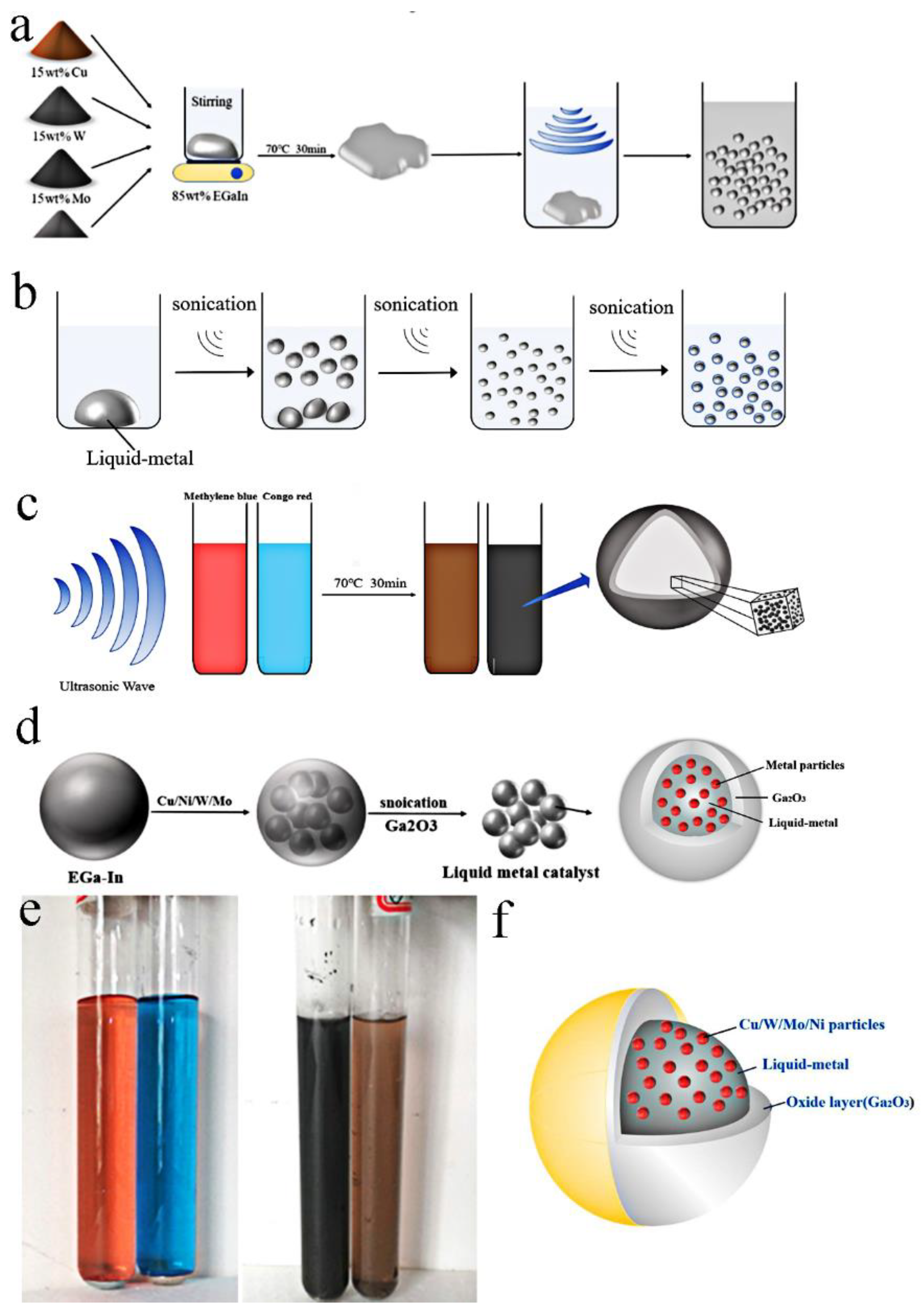
As illustrated in Figure 1a, four kinds of nanoparticles Cu/W/Mo/Ni (15 wt.%, 50 nm) and liquid metals (85 wt.%) were put into different beakers and stirred at 70 °C for 30 min. Then, the stirred composite liquid metal catalysts (samples Cu-LM, W-LM, Mo-LM, Ni-LM) were put into 100 mL methylene blue (MB) and Congo red (CR) solution, respectively (Figure 1c). The eight groups of samples were ultrasonically treated for 1 h (Figure 1e). The sound waves emitted by the ultrasound further reduced the scale of the composite liquid metal catalysts (Figure 1b). Finally, spherical LM catalysts with micrometer scales were formed, as shown in Figure 1b–d. This “shell-core model” catalyst with a size of 5~20 μm was prepared.
As illustrated in Figure 1e, when the liquid metal was added into CR (red color) and MB solution (blue color), the colors of the solution turned brown and black after the ultrasound. Figure 1f illustrated this core-shell structure of LM catalysts. The spherical nucleus was pure liquid metal material doped with nanoparticles Cu/W/Mo/Ni; the shell layer was solid gallium oxide Ga2O3. Owing to LM could react with oxygen in the water to form an oxide layer with a very thin thickness [28], the spherical composite catalyst with core-shell structure could be prepared.
3.2. Characterization
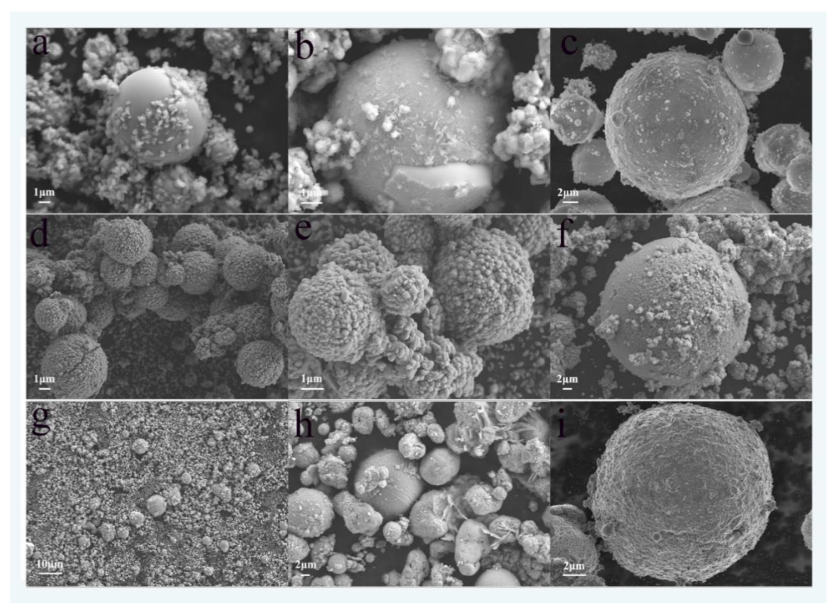
Figure 2 illustrates the scanning micrographs and morphology of core-shell Cu/W/Mo/Ni-LM catalyst samples.
In all the Cu/W/Mo/Ni-LM samples, these samples were mainly spherical structures, and had micro/nano sizes with size distribution ranging from 5 to 20 μm. Figure 2a shows the SEM image of the Ni-LM micro-particle, and on the spherical surface of the Ni-LM catalyst there were small particles of nano Ni. Figure 2b shows the SEM images of Mo-LM particles. The figure shows that there were different degrees of gallium oxides (Ga2O3) on the surface of the catalysts. The gray rough shell layer was the Ga2O3, and the white and smooth core of the sphere was pure liquid metal. Figure 2c–g,i shows the SEM of the W-LM catalyst with a draped and viscoelastic oxide layer. The surface of the W-LM catalysts showed regular rough cluster structures with different sizes. There were also granular materials (Ga2O3) which had rough and uneven patches that covered a subspherical surface. When the oxide particles were large, the oxides on the catalyst surface could accumulate (Figure 2d,e). Figure 2h shows the SEM images of Cu-LM catalysts. There were also small Cu particles on the spherical surface of the Cu-LM catalyst.
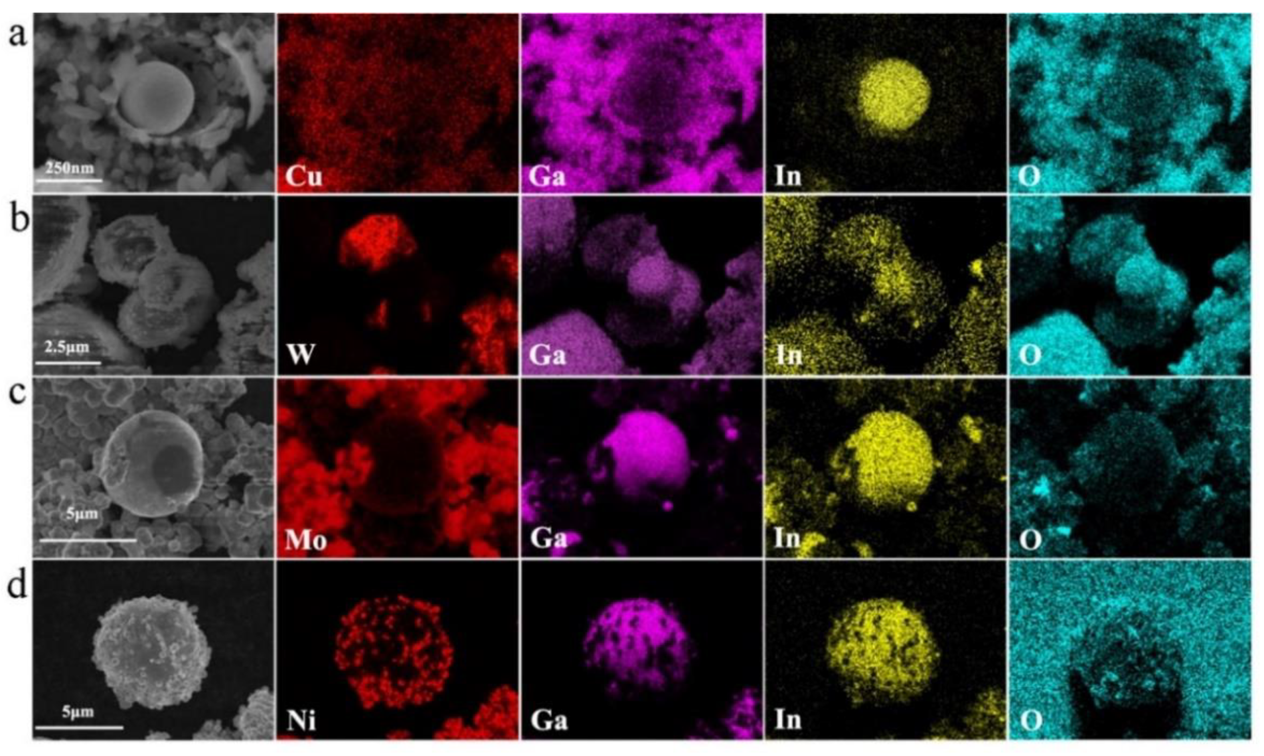
Moreover, under prolonged exposure to ultrasonic waves, the scale of some liquid metal catalysts with core-shell structure could reach the nanoscale (about 250 nm), as shown in Figure 3a.
The composition of micro/nano LM catalysts was determined by energy-dispersive spectroscopy (EDS). Figure 3a–d shows the element distribution of Cu, W, Mo, Ni, Ga, In, and O in the Cu/W/Mo/Ni-LM sample, respectively. It could be seen that on the micron scale, Cu, W, Mo, and Ni existed on the surface of the spherical catalyst, and the central part of the catalyst was also occupied by Cu, W, Mo, and Ni, respectively. The core of the particle was also occupied by all elements of the liquid metal catalyst (Ga and In). EDS data indicate that particles usually had core-shell structures with different element distributions. It shows that the four catalysts all had core-shell heterostructure.
However, a large number of Ga and In elements were detected on the catalyst shell. Compared with Ga and In, the content of four-nanometer metals Cu, W, Mo, and Ni was smaller. Ni metal dispersion was the best, and the size of Ni nanoparticles was about 50 nm. The dispersion of Mo metal in liquid metal spherical particles was poor, and only part of the Mo metal was dispersed in the outer layer. It was clear that the nanometer metal powder was evenly dispersed in indium gallium alloy (EGaIn).
The Ga, In, and O elements were detected on the shell of the particle, and the In element was found in the kernel of the particle. Large amounts of oxygen (O) could be observed in the sample’s shell due to selective oxidation of the liquid metal surface during the ultrasound. Other studies have shown that the surface of the liquid metal was very smooth, and the oxidation of the liquid metal formed a two-dimensional layer [29].
The results show that these metals were well mixed with liquid metals (EGaIn) and evenly distributed in the particles. The catalyst particles prepared have an oxide shell and a metal core. Therefore, the progressive and selective oxidation of the sample would produce metal oxide on the particle surface during the ultrasonic treatment. The composite liquid metal catalyst particles with metal oxide shell and metalcore could be obtained by the ultrasonic method.
3.3. The Photocatalysis of Core-Shell LM Catalysts
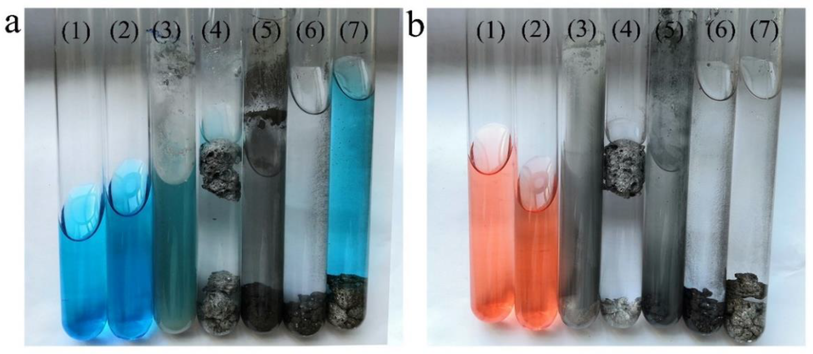
The photocatalytic degradation of organic dyes by the compound LM was studied. Figure 4 shows the experimental results of adding four catalysts to degrade methylene blue and Congo red. It can be seen from Figure 4a that tube (1) is a methylene blue original solution. Tube (2) is the methylene blue solution after being exposed to ultraviolet light. Tube (3) is the pure liquid metal nano-particles-degrading methylene blue solution. Tubes (4–7) are the methylene blue solution with Cu-LM, W-LM, Mo-LM, and Ni-LM catalysts under UV.
As a contrast, Figure 4b shows a series of photos of Congo red degradation after a liquid metal catalyst was added. Tube (1) is Congo red solution. Tube (2) is the Congo red solution under UV irradiation. Tube (3) is the pure liquid metal nano-particles-degrading Congo red solution. Tubes (4–7) are Congo red solutions with Cu-LM, W-LM, Mo-LM, and Ni-LM catalysts under UV.
As can be seen from Figure 4, after 20 h, the catalysts added with Cu/W/Mo/Ni-LM had an excellent degradation effect on methylene blue and Congo red. The blueness of the methylene blue solution decreased, and the solution after degradation was clarified. At the same time, the degradation effect of samples with Cu/W/Mo/Ni-LM catalyst was better than that of pure LM nanoparticles, which could be seen from the transparency of the organic dyes solution (See form the Supporting Information Video S1).
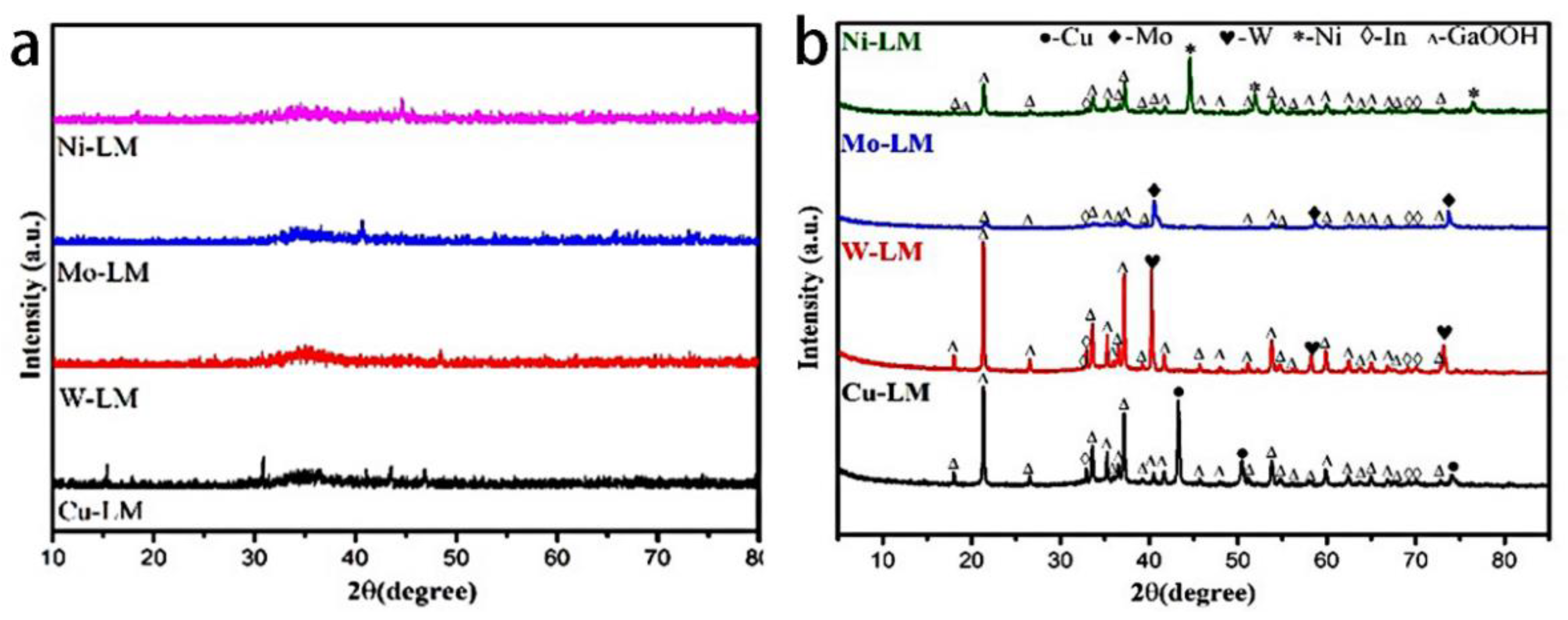
To understand what happened during the catalytic process, XRD and XPS tests of the Cu/W/Mo/Ni-LM catalysts were performed. Figure 5a showed the XRD patterns of samples of Cu/W/Mo/Ni-LM before catalytic reaction. As shown in Figure 5a, XRD analysis showed that the Cu/W/Mo/Ni-LM catalyst mainly existed in the amorphous form before the reaction. In Cu-LM catalyst, Ga, In and Cu were correlated peaks. Similar to Cu-LM, the other three W/Mo/Ni-LM samples also existed in the forms of Ga, In, and metallic elemental W, Mo, Ni, and their correlated peak positions were not obvious.
Figure 5b shows the XRD pattern of brown solid precipitates after photocatalysis of 20 h, which were obtained by the photocatalysis of methylene blue solution with four different Cu/W/Mo/Ni-LM catalysts. These brown sponges were obtained at the bottom of methylene blue solution after photocatalysis. The precipitation products collected on the solution were then characterized in detail. According to the XRD spectrum, it could be seen that four kinds of metal nano-particles existed in the products after catalysis, as the diffraction peaks of Cu, W, Mo, and Ni could be found. At the same time, there was liquid metal in the products, as the diffraction peaks of In could also be found. The diffraction file PDF CARDS used for matching were: Cu metal (PDF#85-1326), W metal (PDF#04-0806), Mo metal (PDF#42-1120), Ni metal (PDF#04-0850), and In metal (PDF#85-1409).
Simultaneously, four catalyst products formed the same hydroxyl oxide. It could be seen from the XRD diagrams, after the reaction, each of the four samples could see the characteristic peak of GaOOH. The powder diffraction PDF card for matching the pattern was GaOOH (PDF#06-0180), which corresponds to the GaOOH [30]. Therefore, in combination with the phenomena in the catalytic process, it could be concluded that during the catalytic process, a part of the LM changed from its original binding state to GaOOH due to the corresponding chemical reaction between Ga and water, which caused the loss of part of LM and resulted in the formation of spongy sediments. See the reaction Equation (1) below:
2Ga + 4H2O = 2GaOOH + 3H2
In fact, this experimental phenomenon has also been reported in other literature [29]. However, after 20 h of catalysis, most liquid metal catalysts still maintained the existence of liquid metal alloy and could be transformed into the nano-state again by ultrasound.
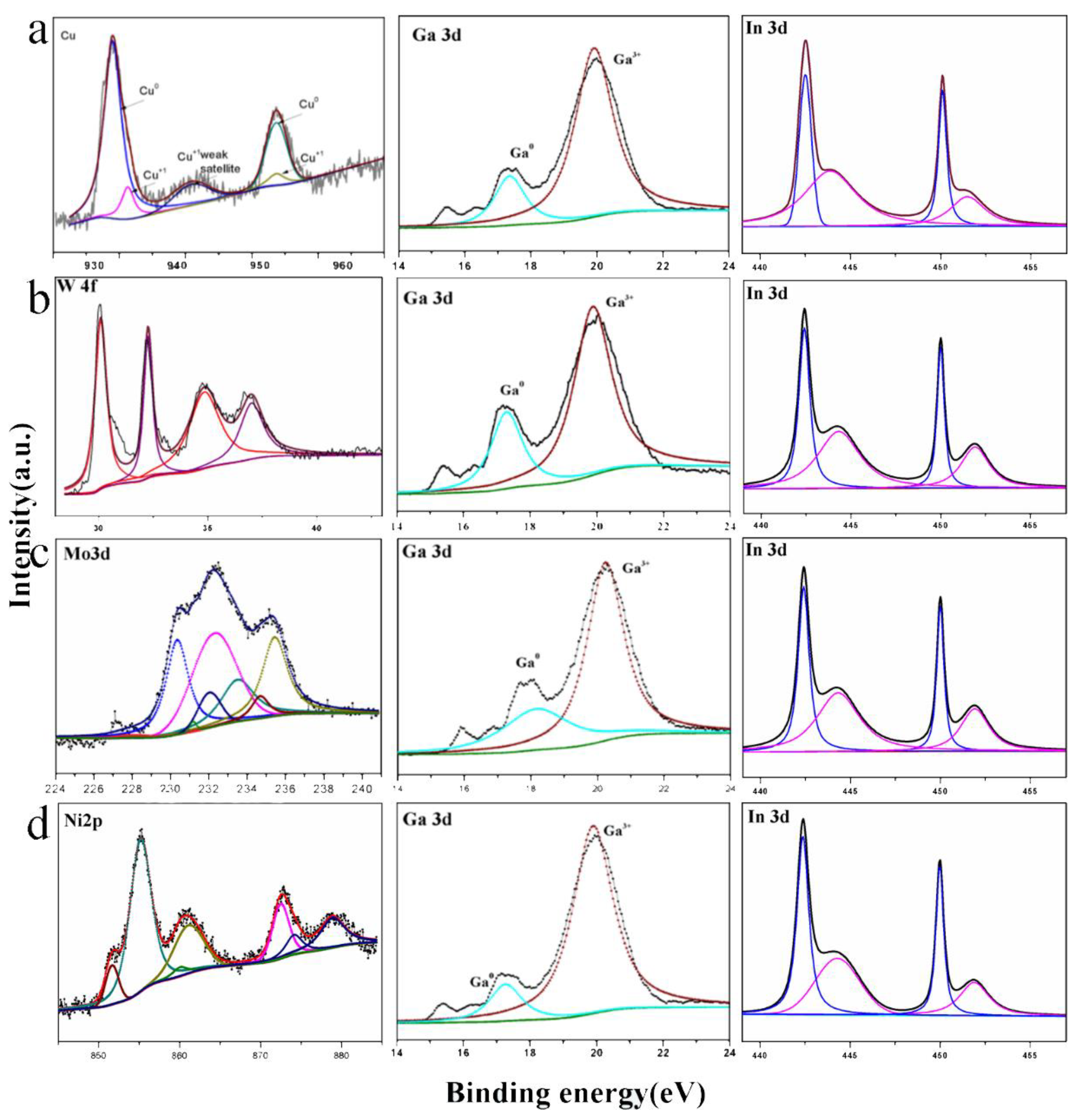
To further confirm the XRD results, the X-ray photoelectron spectroscopy (XPS) technique, which is more sensitive to surface composition analysis, was used to analyze the stoichiometry and chemical bonding state of the reactive samples. Figure 6a–d shows the XPS spectra of the products after photocatalytic methylene blue catalyzed by Cu/W/Mo/Ni-LM, respectively.
As can be seen from Figure 6a–d, the binding energy of Ga was almost the same for the four catalyzed products. Where the brown line represented the peak of Ga3+, the blue line represented the Ga0+ peaks. Ga represented Ga 3d5/2 and Ga 3d3/2 at binding energies of 18.48 eV and 20.68 eV, respectively, and the relationship between chemical bond states and Ga 3d orbitals in the four samples. The binding energy of EGaIn was decomposed into gallium (Ga0) and oxidation state (Ga3+). Thus, the XPS analytical of the surface of gallium produced oxidized-state Ga3+ after catalytic completion, which further proves that GaOOH’s existence was justified.
Meanwhile, it can be seen from Figure 6a–d that the binding energy of In was almost the same. The blue line represents the peak of In3+; the red line represents the In0+ peaks. It represents In 3d5/2 and In 3d3/2 at the binding energies of 443.8 eV and 451.4 eV, respectively.
3.4. The Discussion of Degradation Rates and Mechanism
The degradation rates and efficiencies of several dyes were also analyzed using UV-vis. The properties of liquid metal photocatalyst were studied by ultraviolet-visible absorption spectrum. In 100 mL methylene blue and Congo red solution (20 mg/L), 0.1 g liquid metal catalyst was ultrasonically treated to obtain micro/nano-catalyst to make the catalyst have as much area as possible in the solution. When the methylene blue solution of 20 mg/L was degraded by ultraviolet light at 365 nm, degradation performance significantly increased by adding catalyst.
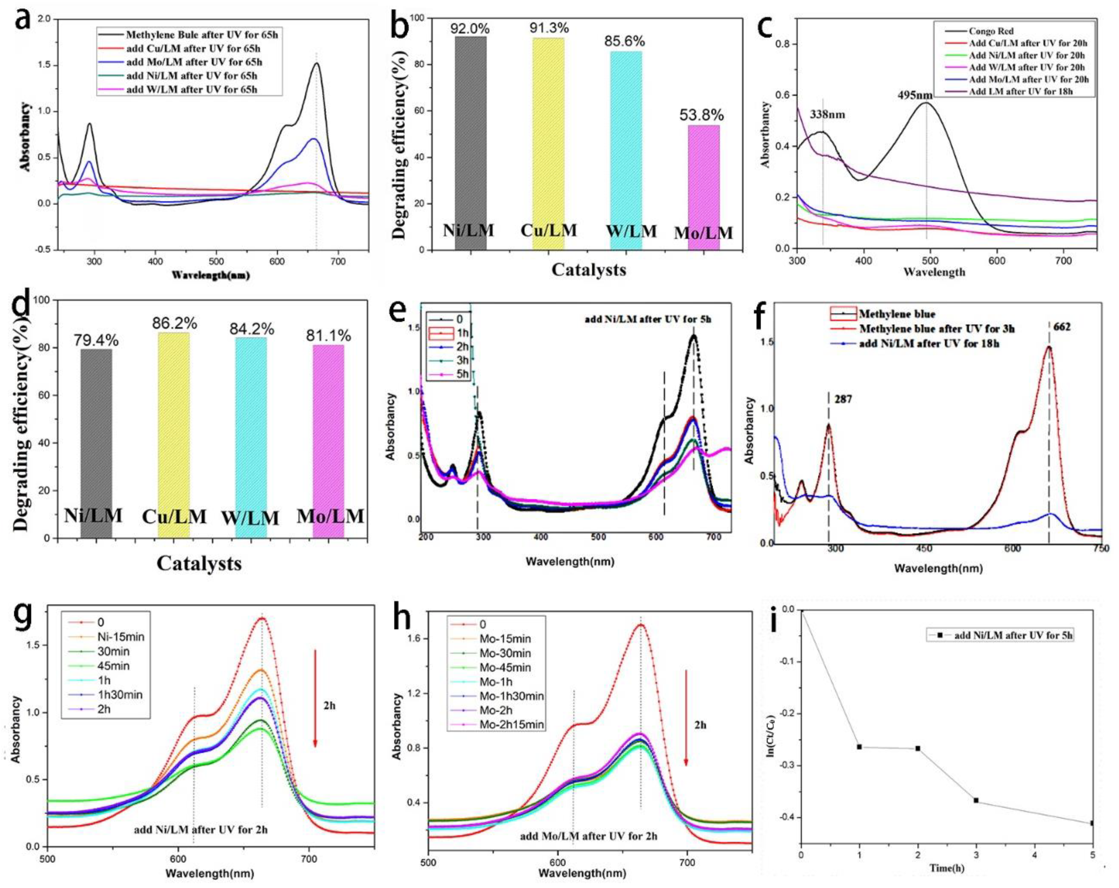
Figure 7a,b shows the catalytic degradation of methylene blue by adding Cu-LM, W-LM, Mo-LM, and Ni-LM for 65 h. As can be seen from Figure 7a,b, the peaks at 287 nm and 662 nm respectively represent methylene blue’s chromophobe group and chromophobe group. The so-called chromophobe group is the unsaturated group that produces ultraviolet or visible absorption. The chromophore is the group that has no ultraviolet absorption, but the chromophore absorption peak can be strengthened. The methylene blue solution with the addition of four catalysts had different degrees of degradation effect, which reduced the peak strength associated with methylene blue respectively. It could be noted that under the same conditions, the rate of these significant catalytic degradation reactions depends on the type of nano-metal powder added to the catalyst.
The degradation rate of methylene blue was calculated according to Formula (2):
degradation rate D = (C0 − Ct)/C0 × 100% = (A0 − At)/A0 × 100%
D was the degradation rate. After degradation, Ct was the concentration of methylene blue at time T = t; C0 was the initial concentration of methylene blue. The absorbency rate (A%) was one indicator to characterize the decrease of organic dye concentration. Where A0 is the absorbance of the solution to reaction time t = 0, and At is the absorbance of solution At reaction time T.
For Ni-LM, the degradation rate D = (1.52624 − 0.12203)/1.52644 × 100% = 92.005%). As shown in Figure 5a,b, the degradation rates of methylene blue by the other three liquid metal catalysts Cu-LM, W-LM, Mo-LM were 91.378%, 85.608%, and 53.769%, respectively. Therefore, it is not difficult to see that the performance of these four catalysts for methylene blue catalytic effect is, in turn: Ni-LM > Cu-LM > W-LM > Mo-LM.
Figure 7c,d shows the catalytic degradation of Congo red by adding Cu-LM, W-LM, Mo-LM, and Ni-LM for 20 h. As can be seen from Figure 7c,d, the Congo red solution with the addition of four catalysts had different degrees of degradation effect. The degradation rates of Congo red by the four liquid metal catalysts Ni-LM, Cu-LM, W-LM, Mo-LM could also be calculated according to Formula (2); they were 79.4%, 86.2%, 84.2%, and 81.1%, respectively. The Cu-LM catalyst has the best catalytic degradation effect on Congo red, and the degradation rate of the Cu-LM catalyst can reach 86.2%. Compared with the reported literature [31], the degradation rate of Ag-doped liquid metal (BiInSn) to Congo red and methylene blue was only 44% and 65%, respectively. Compared with published data, the degradation efficiency of prepared samples has better degradation efficiency.
Figure 7g,h shows the degradation curve of methylene blue after 2 h photocatalytic degradation with the addition of Ni-LM and Mo-LM shell catalyst, respectively. It can be seen from the curve that the peak value of 650 nm was the maximum absorption peak of methylene blue, and the wavelength corresponding to the maximum absorption peak represents the characteristic absorption of methylene blue in the UV-visible spectrum. After the addition of the catalyst of 2 h, the catalyst had a very good catalytic degradation of methylene blue.
Figure 7e,f shows the degradation curve of methylene blue after adding Ni-LM for 5 h and 18 h, respectively. The reaction kinetics were analyzed in Figure 7i, which shows the degradation rate In(Ct/C0) and the time of methylene blue for 5 h. The kinetic analysis of the degradation formula is shown in (3); then, the degradation rate of methylene blue was calculated.
The kinetic equation was calculated according to the Formula (3):
where Ct was the concentration of methylene blue at time T = t; C0 was the initial concentration of methylene blue. k1 = −1.5396 × 10⁻¹ s−1. The linear results show that the degradation reaction conformed to first-order kinetics.
In(Ct/C0) = −1.5396 × 10⁻¹ t, k1 = −1.5396 × 10⁻¹ s−1
4. Discussion
By adding other noble metals (Cu/W/Mo/Ni) to liquid metals and modifying or dissolving them, intermetallic compounds were formed. The electronic structure of supported liquid metal catalysts was changed so that their catalytic performance in reduction or oxidation reactions was significantly improved. According to the literature [31,32], the physic spectral properties of Ag-doped liquid metal were different from pure liquid metal. The Ag-doped liquid metal does not change the conduction band (CB), but their valence band (VB). The valence band of the Ag-doped LM favors generating OH radicals (2.72 V) and therefore those samples may exhibit higher activity if the dyes are degraded through this mechanism. In comparison to the pure liquid metal particles, metallic nanoparticles, such as Ni, Cu, W, Mo, Ag, etc., could utilize the surface plasma effect to increase visible light absorption; metals (such as Ag) show a higher photocatalytic degradation activity towards Congo red. Thus, metal-doped liquid metal improves the catalytic activity of metal.
The mechanism of liquid metal photocatalytic decomposition of organic pollutants is mainly caused by the Ga2O3 semiconductor on its surface [33,34]. According to KK Z et al., gallium oxide has the advantage of providing photogenerated charge, and the bandgap was reported to be 4.2~4.9 eV [29]. As the outer skin of the catalyst has a solid Ga2O3 semiconductor, and the inner core is a reductive liquid metal environment (Cu/W/Mo/Ni mixed Ga metal), it has a high-density oxygen vacancy. Under UV irradiation, a considerable number of electron-hole pairs were generated in the Ga2O3 semiconductor, and electrons can be transferred to the core of Cu/W/Mo/Ni mixed Ga liquid metal to achieve effective charge separation, thus accelerating photocatalysis and promoting the decomposition of organic pollutants.
5. Conclusions
In this work, spherical-shell composite heterogeneous catalysts based on liquid metal to degradation of organic pollutants were introduced. Different Cu/W/Mo/Ni metal nanoparticles were loaded onto LM catalysts to improve the degree of functionalization. Synthesized by ultrasonic agitation, the obtained composite liquid metal catalyst was thoroughly characterized. The photocatalytic performance of the composite catalyst was investigated for the degradation of Congo red and methylene blue under UV irradiation.
The synthesis and photocatalysis details of Cu/W/Mo/Ni-LM nanocomposites were studied. When compared with the LM doped by other Cu/W/Mo metal particles, modifying the LM with nano Ni metal could maximin improve the photocatalysis activity towards methylene blue. The influence of the composite LM catalyst on the degradation rate of pollutants under different conditions was also analyzed. This work provided a solution to the emerging field of LM catalysts and expanded the application of LM in the field of environmental protection and energy. To provide a solution for the emerging field of liquid metal catalysts, it is expected to greatly reshape classical catalytic science and expand the application of liquid metals in the field of environment and energy.
Supplementary Materials
The following is available online at https://0-www-mdpi-com.brum.beds.ac.uk/article/10.3390/catal11111419/s1, Video S1: Cu/W/Mo/Ni-liquid metal catalyst for photocatalytic degradation. Supporting Information Video S1 is available from the online library or from the author.
Author Contributions
S.L. oversaw the whole trial, and wrote the manuscript; C.W. wrote part of the manuscript and assisted with sampling and laboratory analyses; F.L. and G.S. assisted with editing and laboratory analyses. All authors have read and agreed to the published version of the manuscript.
Funding
This work is partially supported by the Natural Science Foundation of Chongqing (No. cstc2019jcyj-msxmX0788), the Science and Technology Research Program of Chongqing Municipal Education Commission China (Grant No. KJQN201901342); this work was also supported by the Foundation for Major Cultivation Program of Chongqing University of Arts and Sciences (No. P2018CH10).
Data Availability Statement
The datasets supporting the conclusions of this article are included within the article.
Acknowledgments
The authors expressed gratefulness for helpful comments from reviewer and editor to improve this manuscript.
Conflicts of Interest
The authors declare no conflict of interest.
References
- Ren, Y.; Sun, X.Y.; Liu, J. Advances in Liquid Metal-Enabled Flexible and Wearable Sensors. Micromachines 2020, 11, 200. [Google Scholar] [CrossRef] [PubMed] [Green Version]
- Elbourne, A.; Cheeseman, S.; Zavabeti, A.; Dickey, M.D.; Zadeh, K.K.; Truong, V.K. Antibacterial Liquid Metals: Biofilm Treatment via Magnetic Activation. ACS Nano 2020, 14, 802–817. [Google Scholar] [CrossRef] [PubMed]
- Choi, Y.Y.; Dong, H.H.; Cho, J.H. Self-Healable Hydrogel–Liquid Metal Composite Platform Enabled by a 3D Printed Stamp for a Multimodular Sensor System. ACS Appl. Mater. Interfaces 2020, 8, 9824–9832. [Google Scholar] [CrossRef] [PubMed]
- He, S.; Zhou, C.X.; Chen, H.L.; Su, X.; Hanc, T. Super soft conductor based on liquid metal/cotton composite. J. Mater. Chem. C 2020, 8, 3553–3561. [Google Scholar] [CrossRef]
- Yuan, T.B.; Hu, Z.; Zhao, Y.X.; Fang, J.J.; Lv, J.; Zhang, Q.H.; Zhuang, Z.B.; Gu, L.; Hu, S. Two-Dimensional Amorphous SnOx from Liquid Metal: Mass Production, Phase Transfer, and Electrocatalytic CO2 Reduction toward Formic Acid. Nano Lett. 2020, 20, 2916–2922. [Google Scholar] [CrossRef] [PubMed]
- Wang, L.; Gao, Y.F.; Wang, X.J.; Cai, R.X.; Chung, C.C.; Iftikhar, S.; Wang, W.; Li, F.X. Liquid Metal Shell as an Effective Iron Oxide Modifier for Redox-Based Hydrogen Production at Intermediate Temperatures. ACS Catal. 2021, 11, 10228–10238. [Google Scholar] [CrossRef]
- Jin, C.; Zhang, J.; Li, X.K.; Yang, X.Y.; Li, J.J.; Liu, J. Injectable 3-D Fabrication of Medical Electronics at the Target Biological Tissues. Sci. Rep. 2013, 3, 3442. [Google Scholar] [CrossRef] [Green Version]
- Liang, S.T.; Liu, J. Progress, mechanism, and application of liquid metal catalysis system: A Review. Chem. Eur. J. 2018, 24, 17616. [Google Scholar] [CrossRef] [PubMed]
- Zhang, Q.; Gao, Y.; Liu, J. Atomized spraying of liquid metal droplets on desired substrate surfaces as a generalized way for ubiquitous printed electronics. Appl. Phys. 2014, 116, 1091–1097. [Google Scholar] [CrossRef]
- Zhu, J.Y.; Tang, S.Y.; Khoshmanesh, K.; Ghorbani, K. An Integrated Liquid Cooling System Based on Galinstan Liquid Metal Droplets. ACS Appl. Mater. Inter. 2016, 8, 2173–2180. [Google Scholar] [CrossRef] [PubMed]
- He, J.F.; Liang, S.T.; Li, F.J.; Yang, Q.B.; Huang, M.J.; He, Y.; Fan, X.N.; Wu, M.L. Recent Development in Liquid Metal Materials. ChemistryOpen 2021, 10, 1–14. [Google Scholar] [CrossRef] [PubMed]
- Tabatabai, A.; Fassler, A.; Usiak, C.; Majidi, C. Liquid-Phase Gallium–Indium Alloy Electronics with Microcontact Printing. Langmuir 2013, 29, 6194–6220. [Google Scholar] [CrossRef] [PubMed]
- Liang, S.T.; Wang, H.Z.; Liu, J. Spray printing and encapsulated liquid metal as a highly reflective metallic paint for packing products. Sci. China Technol. Sci. 2019, 62, 1577–1584. [Google Scholar] [CrossRef]
- Tan, L.; Zeng, M.; Wu, Q.; Chen, L.; Wang, J.; Zhang, T.; Eckert, J.; Remmeli, M.H.; Fu, L. Direct Growth of Ultrafast Transparent Single-Layer Graphene Defoggers. Small 2015, 11, 1840–1846. [Google Scholar] [CrossRef] [PubMed]
- Tang, S.Y.; Zhu, J.; Sivan, V.; Gol, B.; Soffe, R.; Zhang, W.; Mitchell, A.; Khoshmanesh, K. Creation of Liquid Metal 3D Microstructures Using Dielectrophoresis. Adv. Funct. Mater. 2015, 25, 4445–4452. [Google Scholar] [CrossRef]
- Zhang, W.; Naidu, B.S.; Ou, J.Z.; O’Mullane, A.P.; Chrimes, A.F.; Carey, B.J.; Wang, Y.; Tang, S.; Sivan, Y.; Mitchell, V.A.; et al. Liquid Metal/Metal Oxide Frameworks with Incorporated Ga2O3 for Photocatalysis. ACS Appl. Mater. Interfaces 2015, 7, 1943–1948. [Google Scholar] [CrossRef] [Green Version]
- Li, H.; Yang, Y.; Liu, J. Printable tiny thermocouple by liquid metal gallium and its matching metal. Appl. Phys. Lett. 2012, 101, 073511. [Google Scholar] [CrossRef]
- Armbrester, M.; Kovnir, K.; Behrens, M.; Teschner, D.; Grin, Y.; Schlçgl, R. Pd−Ga Intermetallic Compounds as Highly Selective Semihydrogenation Catalysts. J. Am. Chem. Soc. 2010, 132, 14745–14747. [Google Scholar] [CrossRef]
- Redekop, E.A.; Galvita, V.V.; Poelman, H.; Bliznuk, V.; Detavernier, C.; Marin, G.B. Delivering a Modifying Element to Metal Nanoparticles via Support: Pt–Ga Alloying during the Reduction of Pt/Mg(Al,Ga)Ox Catalysts and Its Effects on Propane Dehydrogenation. ACS Catal. 2014, 4, 1812–1824. [Google Scholar] [CrossRef]
- Cheng, S.; Wu, Z. A Microfluidic, Reversibly Stretchable, Large-Area Wireless Strain Sensor. Adv. Funct. Mater. 2011, 21, 2282. [Google Scholar] [CrossRef]
- Lae, P.Y.; Carmel, M.; Rebecca, K.; Phillipe, B.; Robert, J.W. Hyperelastic pressure sensing with a liquid-embedded elastomer. J. Micromech. Microeng. 2010, 20, 125029. [Google Scholar]
- Hutter, T.; Bauer WA, C.; Elliott, S.R.; Huck, W.T.S. Formation of Spherical and Non-Spherical Eutectic Gallium-Indium Liquid-Metal Microdroplets in Microfluidic Channels at Room Temperature. Adv. Funct. Mater. 2012, 22, 2624. [Google Scholar] [CrossRef]
- Gao, M.; Gui, L. A handy liquid metal based electroosmotic flow pump. Lab Chip 2014, 14, 1866–1872. [Google Scholar] [CrossRef] [PubMed]
- Jeong, S.H.; Hagman, A.; Hjort, K.; Jobs, M.; Sundqvist, J.; Wu, Z. Liquid alloy printing of microfluidic stretchable electronics. Lab Chip 2012, 12, 4657–4664. [Google Scholar] [CrossRef] [PubMed]
- Yi, L.; Jin, C.; Wang, L.; Liu, J. Liquid-solid phase transition alloy as reversible and rapid molding bone cement. Biomaterials 2014, 35, 9789–9810. [Google Scholar] [CrossRef] [Green Version]
- Hoshyargar, F.; Khan, H.; Zadeh, K.K.; O’Mullane, A.P. Generation of catalytically active materials from a liquid metal precursor. Chem. Commun. 2015, 51, 14026–14029. [Google Scholar] [CrossRef] [Green Version]
- Esrafilzadeh, D.; Zavabeti, A.; Jalili, R.; Atkin, P.; Choi, J.; Carey, B.J.; Brkljaca, R.; O’Mullane, A.P.; Dickey, M.D.; Officer, D.L.; et al. Room temperature CO2 reduction to solid carbon species on liquid metals featuring atomically thin ceria interfaces. Nat. Commun. 2019, 10, 865–873. [Google Scholar] [CrossRef]
- Chen, S.; Wang, H.Z.; Zhao, R.Q.; Rao, W.; Liu, J. Liquid Metal Composites. Matter 2020, 2, 1446–1480. [Google Scholar] [CrossRef]
- Lu, Y.; Lin, Y.; Chen, Z.W.; Hu, Q.Y.; Liu, Y.; Yu, S.J.; Gao Wei Dickey, M.D.; Gu, Z. Enhanced Endosomal Escape by Light-Fueled Liquid-Metal Transformer. Nano Lett. 2017, 17, 2138–2145. [Google Scholar] [CrossRef]
- Lu, Y.; Lin, Y.; Pacardo, D.B.; Wang, C.; Sun, W.; Ligler, F.S.; Dickey, M.D.; Gu, Z. Transformable liquid-metal nanomedicine. Nat. Commun. 2015, 6, 10066. [Google Scholar] [CrossRef]
- Idrus-Saidi, S.A.; Tang, J.B.; Ghasemian, M.B.; Yang, J.; Han, J.L.; Syed, N.; Daeneke, T.; Abbasi, R.; Koshy, P.; O’Mullane, A.P.; et al. Liquid metal core–shell structures functionalised via mechanical agitation: The example of Field’s metal. J. Mater. Chem. A 2019, 7, 17876–17887. [Google Scholar] [CrossRef]
- Yang, N.L.; Gong, F.; Zhou, Y.K.; Hao, Y.; Dong, Z.L.; Lei, H.; Zhong, L.P.; Yang, X.Y.; Wang, X.W.; Zhao, Y.; et al. A general In-Situ reduction method to prepare core-shell liquid-metal/metal nanoparticles for photothermally enhanced catalytic cancer therapy. Biomaterials 2021, 277, 121125. [Google Scholar] [CrossRef] [PubMed]
- Zeng, M.Q.; Li, L.Y.; Zhu, X.H.; Fu, L. A Liquid Metal Reaction System for Advanced Material Manufacturing. Acc. Mater. Res. 2021, 2, 669–680. [Google Scholar] [CrossRef]
- Zou, Z.X.; Liang, J.W.; Zhang, X.H.; Ma, C.; Xu, P.; Yang, X.; Zeng, Z.X.S.; Sun, X.X.; Zhu, C.G.; Liang, D.L.; et al. Liquid-Metal-Assisted Growth of Vertical GaSe/MoS2 p−n Heterojunctions for Sensitive Self-Driven Photodetectors. ACS Nano 2021, 15, 10039–10047. [Google Scholar] [CrossRef] [PubMed]
Figure 1.
Ultrasonic preparation process: (a) 2 g EGaIn large droplet was mixed with metal nanoparticles in ultrapure water; (b) the process of ultrasonic, smaller liquid metal particles was split; (c) ultrasonic liquid metal particles in an organic solvent, (d,f) the composite shell-nuclear structure of LM catalyst, (e) the CR and MB solution turned into brown and black colors after an ultrasound of LM.

Figure 2.
SEM images of different Cu/W/Mo/Ni-LM particles prepared by the ultrasonication method: (a) the SEM images of Ni-LM particles; (b) the SEM images of Mo-LM particles; (c–g,i) the SEM of oxidized W-LM with a draped and viscoelastic oxide layer; (h) the SEM images of Cu-LM particles.
Figure 2.
SEM images of different Cu/W/Mo/Ni-LM particles prepared by the ultrasonication method: (a) the SEM images of Ni-LM particles; (b) the SEM images of Mo-LM particles; (c–g,i) the SEM of oxidized W-LM with a draped and viscoelastic oxide layer; (h) the SEM images of Cu-LM particles.

Figure 3.
EDX image of Cu/W/Mo/Ni-LM photocatalyst and its elemental mappings: (a) Cu-LM, (b) W-LM, (c) Mo-LM, (d) Ni-LM.
Figure 3.
EDX image of Cu/W/Mo/Ni-LM photocatalyst and its elemental mappings: (a) Cu-LM, (b) W-LM, (c) Mo-LM, (d) Ni-LM.

Figure 4.
The photo of adding four catalysts to degrade methylene blue and Congo red. (a) (1) methylene blue original solution; (2) methylene blue after being exposed to ultraviolet light; (3) pure liquid metal nano-particles-degrading methylene blue; (4–7) methylene blue solution with Cu-LM, W-LM, Mo-LM, and Ni-LM catalysts under UV. (b) (1) Congo red solution; (2) Congo red solution under UV irradiation; (3) pure liquid metal nano-particles-degrading Congo red; (4–7) Congo red solution with Cu-LM, W-LM, Mo-LM, and Ni-LM catalysts under UV.

Figure 5.
X-ray diffraction pattern of Cu/W/Mo/Ni-LM catalysts before (a) and after (b) catalysis.

Figure 6.
XPS spectra of the products after photocatalytic methylene blue catalyzed by Cu/W/Mo/Ni-LM, (a) Cu-LM, (b) W-LM, (c) Mo-LM, (d) Ni-LM.
Figure 6.
XPS spectra of the products after photocatalytic methylene blue catalyzed by Cu/W/Mo/Ni-LM, (a) Cu-LM, (b) W-LM, (c) Mo-LM, (d) Ni-LM.

Figure 7.
The degradation rates of Cu/W/Mo/Ni−LM catalysts: (a,b) the degradation curve and catalytic degradation efficiency of methylene blue by adding Cu/W/Mo/Ni−LM for 65 h; (c,d) degradation curve and degradation efficiency of Congo red by adding Cu/W/Mo/Ni−LM for 20 h; (e,f) degradation curve of methylene blue after adding Ni−LM for 5 h and 18 h, respectively; (g,h) degradation curve of methylene blue after 2 h photocatalytic degradation with Ni−LM and Mo−LM catalyst, respectively; (i) the kinetics of the degradation rate of Ni−LM for 5 h.

Publisher’s Note: MDPI stays neutral with regard to jurisdictional claims in published maps and institutional affiliations. |
© 2021 by the authors. Licensee MDPI, Basel, Switzerland. This article is an open access article distributed under the terms and conditions of the Creative Commons Attribution (CC BY) license (https://creativecommons.org/licenses/by/4.0/).
Share and Cite
MDPI and ACS Style
Liang, S.; Wang, C.; Li, F.; Song, G. Supported Cu/W/Mo/Ni—Liquid Metal Catalyst with Core-Shell Structure for Photocatalytic Degradation. Catalysts 2021, 11, 1419. https://0-doi-org.brum.beds.ac.uk/10.3390/catal11111419
AMA Style
Liang S, Wang C, Li F, Song G. Supported Cu/W/Mo/Ni—Liquid Metal Catalyst with Core-Shell Structure for Photocatalytic Degradation. Catalysts. 2021; 11(11):1419. https://0-doi-org.brum.beds.ac.uk/10.3390/catal11111419
Chicago/Turabian StyleLiang, Shuting, Chaowei Wang, Fengjiao Li, and Gang Song. 2021. "Supported Cu/W/Mo/Ni—Liquid Metal Catalyst with Core-Shell Structure for Photocatalytic Degradation" Catalysts 11, no. 11: 1419. https://0-doi-org.brum.beds.ac.uk/10.3390/catal11111419
Note that from the first issue of 2016, this journal uses article numbers instead of page numbers. See further details here.