
Electrodeposition of Fe-Complexes on Oxide Surfaces for Efficient OER Catalysis


1
Doctoral School on Materials Sciences and Technologies, Óbuda University, H-1034 96/b Bécsi Street, H-1034 Budapest, Hungary
2
Centre for Energy Research, Surface Chemistry and Catalysis Department, 29-33 Konkoly-Thege Street, H-1121 Budapest, Hungary
*
Author to whom correspondence should be addressed.
Catalysts 2021, 11(5), 577; https://0-doi-org.brum.beds.ac.uk/10.3390/catal11050577
Submission received: 29 March 2021
/
Revised: 27 April 2021
/
Accepted: 28 April 2021
/
Published: 30 April 2021
(This article belongs to the Special Issue 10th Anniversary of Catalysts: Achievements in Electrocatalysis for Sustainable Energy Technologies)
Abstract
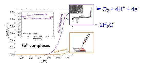
:Progress in non-covalent/self-assembled immobilization methods on (photo)electrode materials for molecular catalysts could broaden the scope of attainable systems. While covalent linkage (though considered more stable) necessitates functional groups introduced by means of often cumbersome synthetic procedures, non-covalent assemblies require sufficient propensity of the molecular unit for surface adsorption, thus set less rigorous pre-requisites. Herein, we report efficient electrodeposition (ED) of two Fe(III) complexes prepared with closely related NN’N pincer ligands yielding stable and active ad-layers for the electrocatalysis of the oxygen-evolving reaction (OER). The ED method is based on the utilization of a chloride precursor complex [FeIIICl2(NN’N)], which is dissolved in an organic electrolyte undergoes chloride/aqua ligand exchange upon addition of water. ED provides patchy distribution of a chloride-depleted catalyst layer on indium tin oxide (ITO) and fluorine-doped tin oxide (FTO) surfaces, which can be applied for long periods as OER electrocatalysts. Compared to drop-casting or layering of [FeIIICl2(NN’N)] with Nafion (a commonly used support for molecular electrocatalysts), the surface modification by ED is a material saving and efficient method to immobilize catalysts.
1. Introduction
Electrochemical water splitting (electrolysis of water) is considered to be an important technology, consented to suppress the usage of fossil fuels since it can help to overcome the storage-reuse obstacles of renewable-based energy systems by producing the green energy carrier H2 [1,2]. The complete reaction in Equation (1) necessitates efficient water oxidation catalysts (WOCs) as functional components of the overall system. A WOC is meant to enhance the efficiency of the oxygen-evolving reaction (OER) thus, aiding solar-to-chemical energy conversion as in the artificial photosynthesis concept [3]. However, the OER from water in Equation (2) is kinetically sluggish, involving the transfer of four electrons and four protons. As a consequence, it means a bottleneck for the overall splitting reaction, where the electrons and protons generated by the anodic OER are used up for the respective formation of H2 in the cathodic reaction in Equation (3), requiring much lower kinetic overpotential [4]:
The complexity and the high oxidation potential required by the OER is an enormous challenge for chemists seeking efficient and robust WOCs, including homogeneous (molecular) and heterogeneous (material) catalysts with preferably low overpotential (η) and high charge efficiency [5,6,7,8]. Note that WOCs as co-catalysts are highly desirable for efficient photoelectrochemical systems, too. Complexes of transition metals that are more abundant and less expensive than Ru and Ir, such as those of Ni [9,10], Cu [11,12], Co [13,14] and Mn [15,16], were reported as molecular WOCs, but Fe as a non-toxic, inexpensive transition metal, and the fourth most abundant element in the earth’s crust, has received distinguished attention too [3,17].
Viable strategies aiming at the immobilization of molecular catalysts have become just as important as enhancing their intrinsic catalytic capabilities. In addition to the often cumbersome covalent grafting of molecular units to electrodes, a number of other fruitful methods are available to fabricate ad-layers, including dip-coating (DIP), drop-casting (DC) and electrodeposition (ED). The latter is inarguably a very attractive method and a unique way to prepare modified electrodes with advantageous electrocatalytic properties [18,19,20,21]. Simplicity, low cost, mild operating conditions, scalability and manufacturability are common advantages of electrodeposition, which often warrants robust attachment of the deposits to the substrate [22]. Moreover, the morphology of the films can be also influenced via the applied electrochemical method [23]. Finally, the oxidation state of precursors is an additional option to control the ad-layer formation.
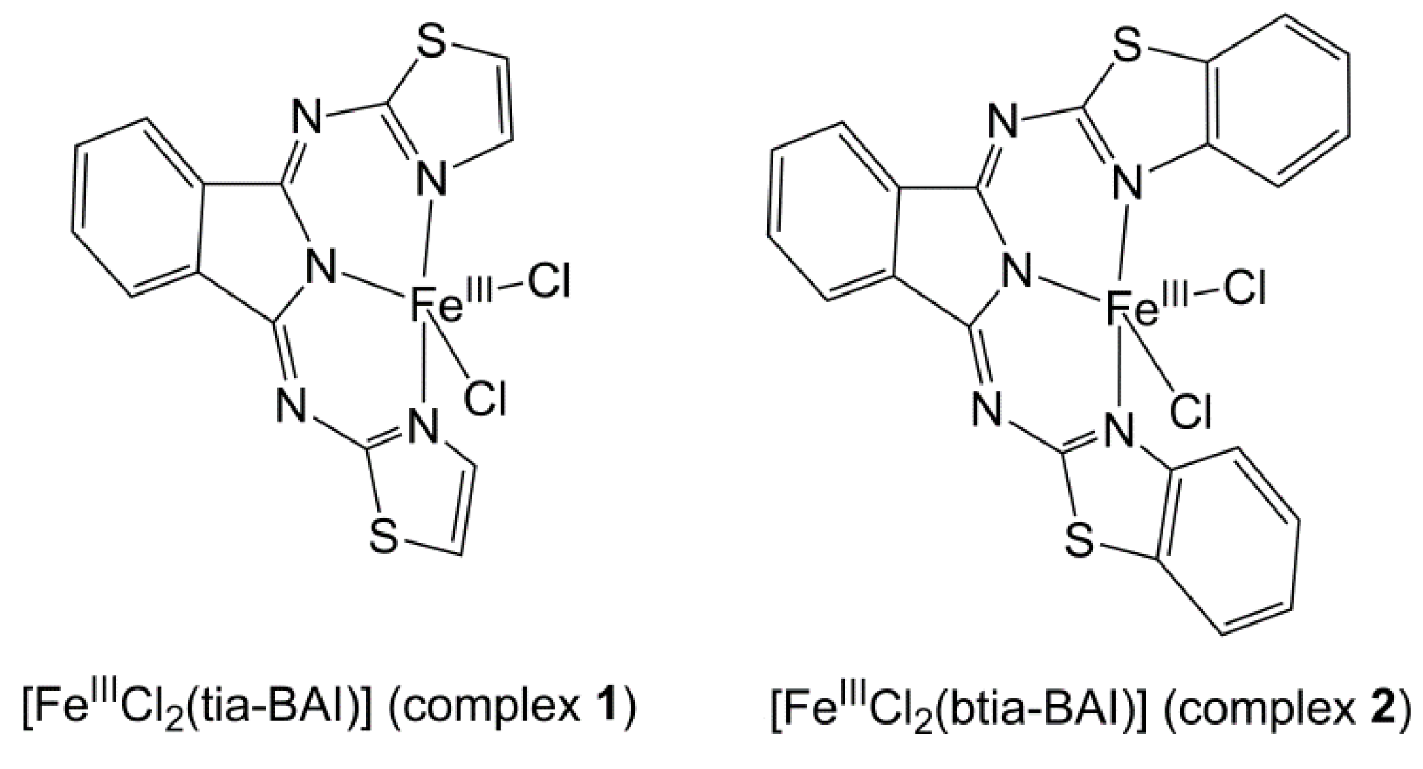
We have recently reported the structurally characterized [FeIIICl2(tia-BAI)] complex (complex 1 in Scheme 1, where tia-BAI− = 1,3-bis(2′-thiazolylimino)isoindolinate(−) ligand) [24] as precursor that could be immobilized on indium tin oxide (ITO) by simple drop-casting [25]. This work was in part inspired by the known coordination chemistry and catalytic oxidation reactions by complexes containing tia-BAIH [26,27,28]. The complex@ITO showed enhanced electrocatalytic OER performance and good stability that could be attributed to the water-insolubility of the FeIII(tia-BAI)2+ assembly. The choice of solvent for the drop-casting of 1 seemed crucial to the OER activity. It was found that methanol promoted chloride dissociation, providing accessible sites for the coordination of water molecules, which in turn is necessary to trigger any catalytic effect in OER (Scheme 1). Samples drop-casted from methanol showed over 80% Faradaic efficiency and turnover number (TON) of 193 in OER. The surface analysis of the used complex@ITO and re-dissolution of the ad-layer suggested an immobilized and nearly chloride-free molecular catalyst.
In addition to the tia-BAI− ligand, which warrants good solubility and thus a detailed solution analysis for complex 1 in various organic solvents, other NN’N pincer ligands would be of interest, too. Ligand homologs with fused aromatic rings would be desirable to favor surface stability of the ad-layer in the aqueous electrolyte and to further investigate the role of ligand oxidation in electrocatalytic OER [24,25]. On the other hand, polycyclics are expected to limit solubility, and the effectiveness of the drop-casting technique that was found suitable for complex 1 and some other Fe-complex precursors earlier [29].
In the present work, we compare how the way of deposition affects the OER performance. As it is shown in Figure 1 (methods A–C), the methods involve drop-casting (DC) and dip-coating (DIP), in combination with Nafion, a common additive for stable deposition of molecular catalysts. We illustrate with the example of the [FeIIICl2(btia-BAI)] complex (2, btia-BAI− = 1,3-bis(2′-benzothiazolylimino)isoindolinate(−)) [24] the effectiveness of electrodeposition (ED) (Figure 1, method D) in a case when methods A–C are unsuited to fabricate catalytically active layers due to poor solubility in the obligate solvent mixtures. Method D affords layers with better charge transfer properties and stability, but beyond that, it seems to be the most atom-efficient, additive-free deposition method found so far for this group of compounds. This simple ED method may represent a viable alternative to be considered in the case of other molecular electrocatalysts, too.
2. Results
2.1. Electrodeposition of Complexes 1 and 2
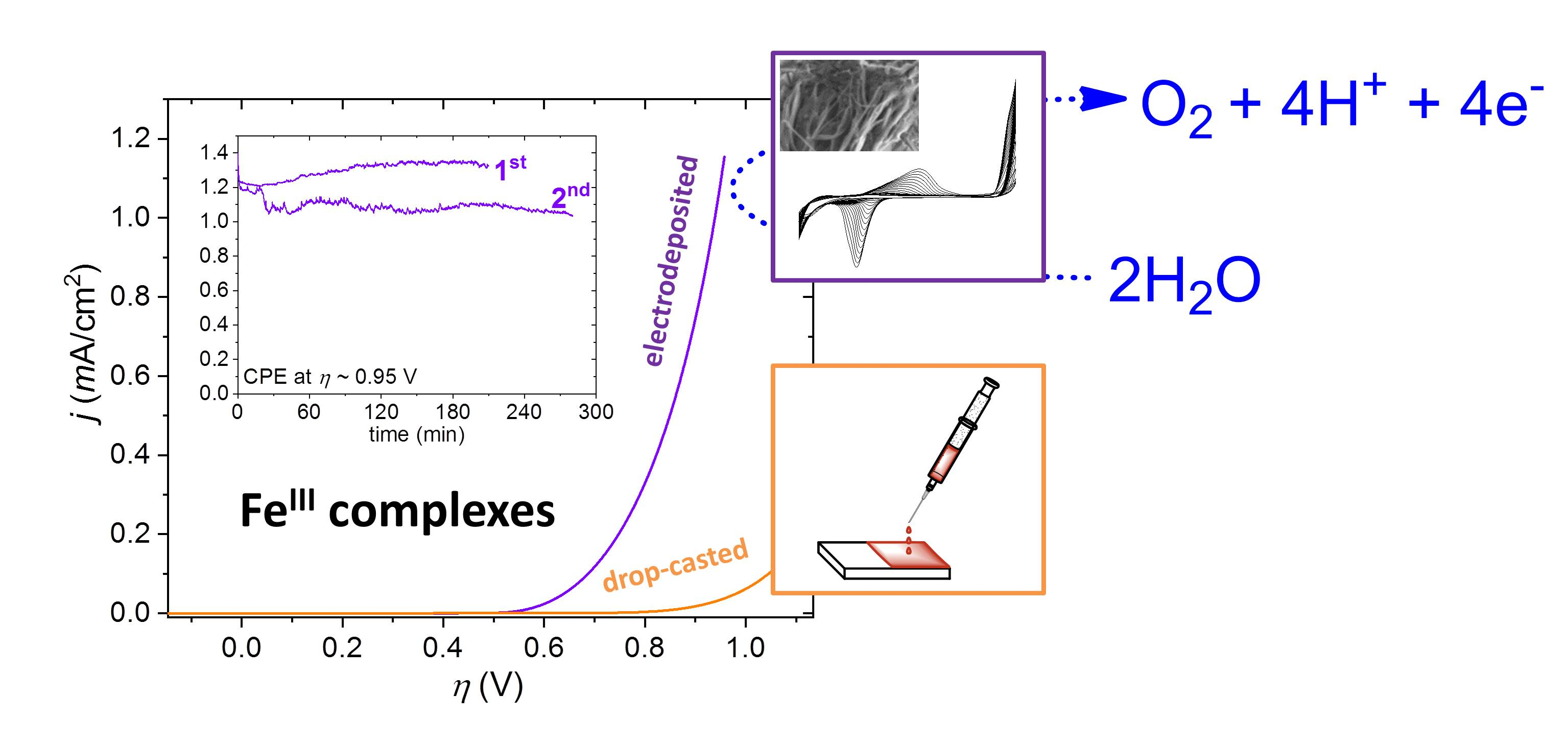
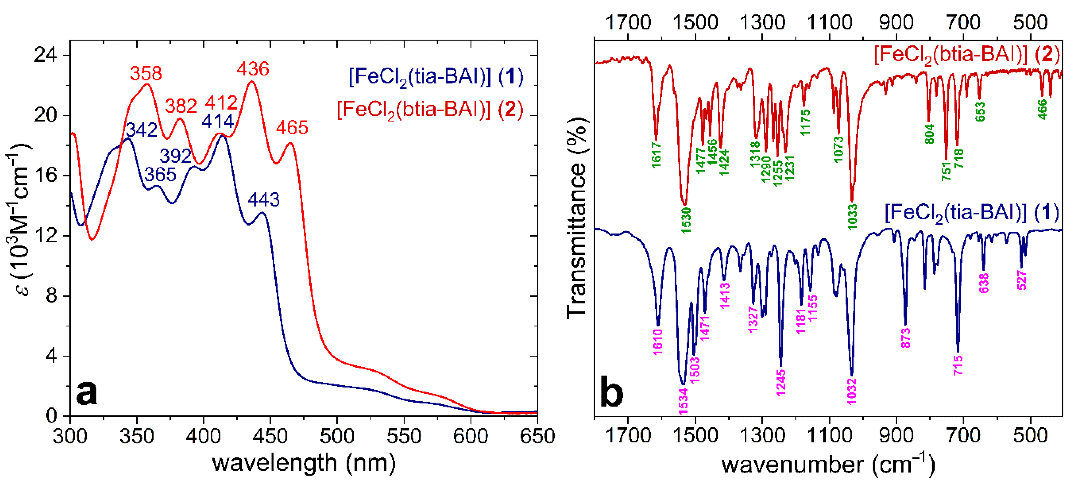
Both complexes are soluble in dichloromethane (DCM), and their electronic absorption spectra are dominated by the very intense intra-ligand charge transfer (ILCT) and the less intense ligand to metal charge transfer (LMCT) bands, as shown in Figure 2a. These features can be related to those of other known Fe-complexes with BAI ligands [30]. The anionic coordination mode of the BAI ligands is clear from the ν(C = N) bands present at 1534 and 1530 cm−1 for 1 and 2, respectively, in the Fourier transform infrared (FTIR) spectra (Figure 2b) [24,30]. Cyclic voltammetry reveals a single, fully reversible Fe(III)/Fe(II) transition at −0.27 V vs. Fc+/Fc for 1 and −0.18 V vs. Fc+/Fc for 2 (Figure 3a, and the blue square wave voltammetry, SWV inset in Figure 3b), indicating a single complex form in DCM. The zero electrolytic conductivity of the solution (~0 μS/cm) indicates that no electrolytic dissociation occurs, and the chloride ligands remain coordinated under these conditions maintaining the trigonal bipyramidal (TBPY-5) geometry around the Fe(III) center. The difference between the redox potential of 1 and 2 thus can be attributed to the weaker donor strength of the btia-BAI ligand in 2 since this ligand should force a larger bite angle together with longer Fe–Nbtia bond distances originating from its steric hindrance.
On the other hand, we reported that chloride could dissociate from complex 1, and eventually, the exchange could be traced by the occurrence of new Fe(III)/Fe(II) redox transitions at more positive potentials in methanol or other organic-aqueous mixtures, such as water in acetone. This could be exploited to fabricate a self-supported complex@electrode ad-layer that was depleted in Cl and showed activity in electrocatalytic OER. The layer made by DC consisted of adsorbed crystallites, in which only some of the complex molecules can participate in catalysis, those, which are close enough to the polarized electrode surface to gain sufficient driving force for the redox events to take place, and at the same time, located near the crystallite surface to get in contact with water molecules. However, in the case of 2, we could not follow the DC or DIP methods (Figure 1, methods A and B), since this compound is practically insoluble in alcohols or other volatile organic solvents that could aid ligand exchange.
This motivated us to seek another method that might lead to an active ad-layer starting from 2 (or other, future complexes) as a precursor. In principle, this should necessitate a suitable organic-aqueous mixture, which allows electrochemistry in the presence of water. Since both 1 and 2 are soluble in DCM, a solvent immiscible with water, we added pre-mixed water-acetone aliquots to their solution in order to achieve a reasonable excess of H2O in the same phase as the complex (note that under the reaction conditions, drops of an aqueous phase was usually observed on the top of the electrolyte). Cyclic voltammetry (CV) scans of 1 or 2 in DCM mixed with acetone-water were recorded under argon (Figure 3a,b, red CVs) using a boron-doped diamond (BDD) working electrode. We could observe one predominant, reversible pair of peaks increasing in intensity from cycle to cycle. This behavior indicates the deposition of an electrochemically active compound, while the symmetrical peak shape, a single immobilized isomer with favorable electron transfer kinetics. (Simply immersing the electrode into the same electrolyte and follow-up CV scan did not show the appearance of the same redox feature. Additionally, when the anodic turning point was lowered below the oxidation starting at +1.1 V vs. Fc+/Fc, the increase in the peaks was negligible and reached a maximum after a few cycles, see Figure S1 of the Electronic Supplementary Information.)
By the 20th cycle, the peak separation is gradually increased, more pronouncedly for 2 (black arrows in Figure 3), while the capacitive current is nearly unchanged, suggesting a slight increase in the electroactive surface area (see the cathodic branches below −0.5 V in Figure 3a,b). These two facts may suggest non-homogeneous deposition yielding unevenly distributed deposits with low specific capacitance. The growing peak separation may originate from the shifting mean value of the electron transfer constants as a result of the growing distance between the deposited compound and the conducting surface with the number of cycles. A plausible morphological explanation would be the thickening of a patchy, non-conducting complex deposit that was indeed observed on ED samples by scanning electron microscopy (vide infra).
The half-wave potential, E1/2 = (Epa + Epc)/2 (where Epc is the potential of the cathodic and Epa is the potential of the anodic peak), is found at +0.16 V vs. Fc+/Fc for the solution made with 1, and +0.23 V vs. Fc+/Fc for that of 2 after 20 cycles (black dashed lines in Figure 3a,b). Note that SWV performed on a cleansed BDD electrode revealed a redox transition at +0.14 V vs. Fc+/Fc for the solution in DCM-acetone-water made with 2 instead of −0.18 V vs. Fc+/Fc in dry DCM (Figure 3b, red SWV inset). A similar shift of the reversible Fe(III)/Fe(II) potential from −0.27 to +0.04 V vs. Fc+/Fc has been associated with chloride-to-aqua ligand substitution in the case of 1 [25], and the same explanation can fit the anodic potential shift for 2.
A second, non-symmetrical oxidation peak at above +1.5 V vs. Fc+/Fc is also apparent in the SWV of 2 in dry DCM (Figure 3b, blue SWV) that can be associated with non-separate ligand-based btia-BAI●/bti-BAI− and metal-based Fe(IV)/Fe(III) oxidations. Earlier, the oxidation had been suggested to generate the (BAI●)FeIV = O2+ ternary unit that was held responsible for carrying out the water-nucleophilic attack (WNA) step [25]. Indeed, when water is present, the catalytic enhancement of this oxidation current is apparent in the case of both complexes (compare blue and red CVs in Figure 3). Finally, based on the good match between the E1/2 potentials for the product formed by chloride-to-aqua ligand substitution in the homogeneous phase and that of the deposited compound, it is reasonable to conclude that an aqua complex is deposited derived from 1 or 2. Efficient ED requires cycling through the anodic potential regime, where the catalytic transformation of the coordinated water molecules takes place. Therefore, the participation of a catalytic intermediate occurring only in the close vicinity of the electrode and exhibiting lowered solubility in the applied solvent mixture is a likely scenario for the buildup of the deposit. However, note that cycling through the Fe(III)/Fe(II) redox transition helps to generate the aqua form by favoring chloride dissociation upon the reduction of the metal center [25]. Based on the sharp, reversible and symmetrical redox peaks for the deposited complex, a single isomeric form is present on the surface of BDD. Note that the redox peaks of the chloride precursor complexes (1 and 2) are suppressed after the first CV cycles that may come from a combination of reasons. First, the solution equilibrium produces the aqua complex, and the bulk concentration of 1 and 2 is reduced. This is clearly seen when the anodic vertex potential is lowered, and only the Fe(III)/Fe(II) redox potentials are scanned (Figure S1). However, after deposition commences, 1 and 2 meet a complex-coated surface, and it attenuates electron transfer; thus, the redox current is diminished (this also implies that the coating on BDD should cover the whole surface).
Importantly, the same ED method worked on neat or Nafion-coated ITO and fluorine-doped tin oxide (FTO) electrodes, too (for the steps followed, see Figure 1). When FTO was immersed in the same mixture as the BDD electrode (see above), a similar redox feature for a surface-adsorbed electroactive species could be observed (Figure 3c,d). The main difference was that the peak separation was greater on FTO (and similarly, on ITO, see Figure S2), mainly due to the anodic shift and broadening of the oxidation current peak, indicating a more sluggish electron transfer kinetics concerning the oxidation of the deposited compound on the oxides compared to that on BDD. This phenomenon was more pronounced for 2 (Figure 3d). These samples from ED experiments were used in a comparison study involving both 1 and 2 immobilized by other methods, as discussed below.
2.2. Performance of the Differently Fabricated, Immobilized Samples of 1 and 2 in Water Oxidation
The immobilized complexes on ITO or FTO were investigated by means of linear sweep voltammetry (LSV) at 5 mV/s and electrochemical impedance spectroscopy (EIS). The same modified surfaces were applied as working electrodes in CA experiments to test their catalytic activity towards the OER (Figure 4a–f, we discuss representative examples). We applied the borate buffer at pH 8.2 since it was found a suitable electrolyte in earlier studies on molecular Fe-based catalysts [25,29]. The solubility of 1 (and the dissociation of its chloride content [25]) in methanol allowed the addition of 1 to Nafion-coated ITO (or FTO) electrodes by the DC and DIP methods (Figure 1). The application of Nafion (Nf) significantly reduced the required amount of complex to create an apparently stable layer on the electrode surface (compared to the earlier published drop-casting with the complex only, the required amount was roughly one order of magnitude lower). The contribution of Nf to the activity was expected to be negligible (indeed, experiments with the DC-Nf@ITO and DIP-Nf@ITO samples made by the drop-casting and dip-coating methods confirmed this presumption, see Figure 4).
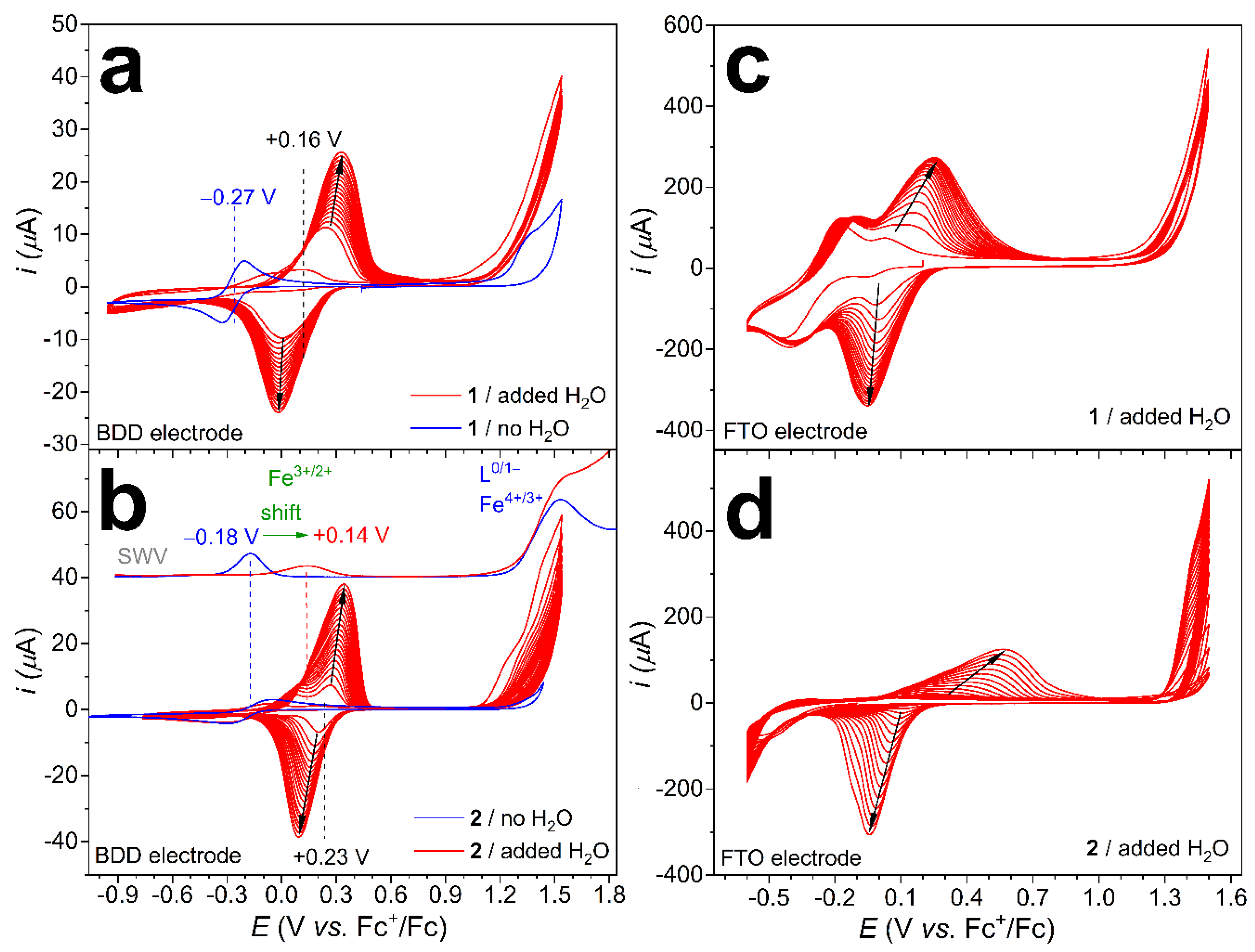
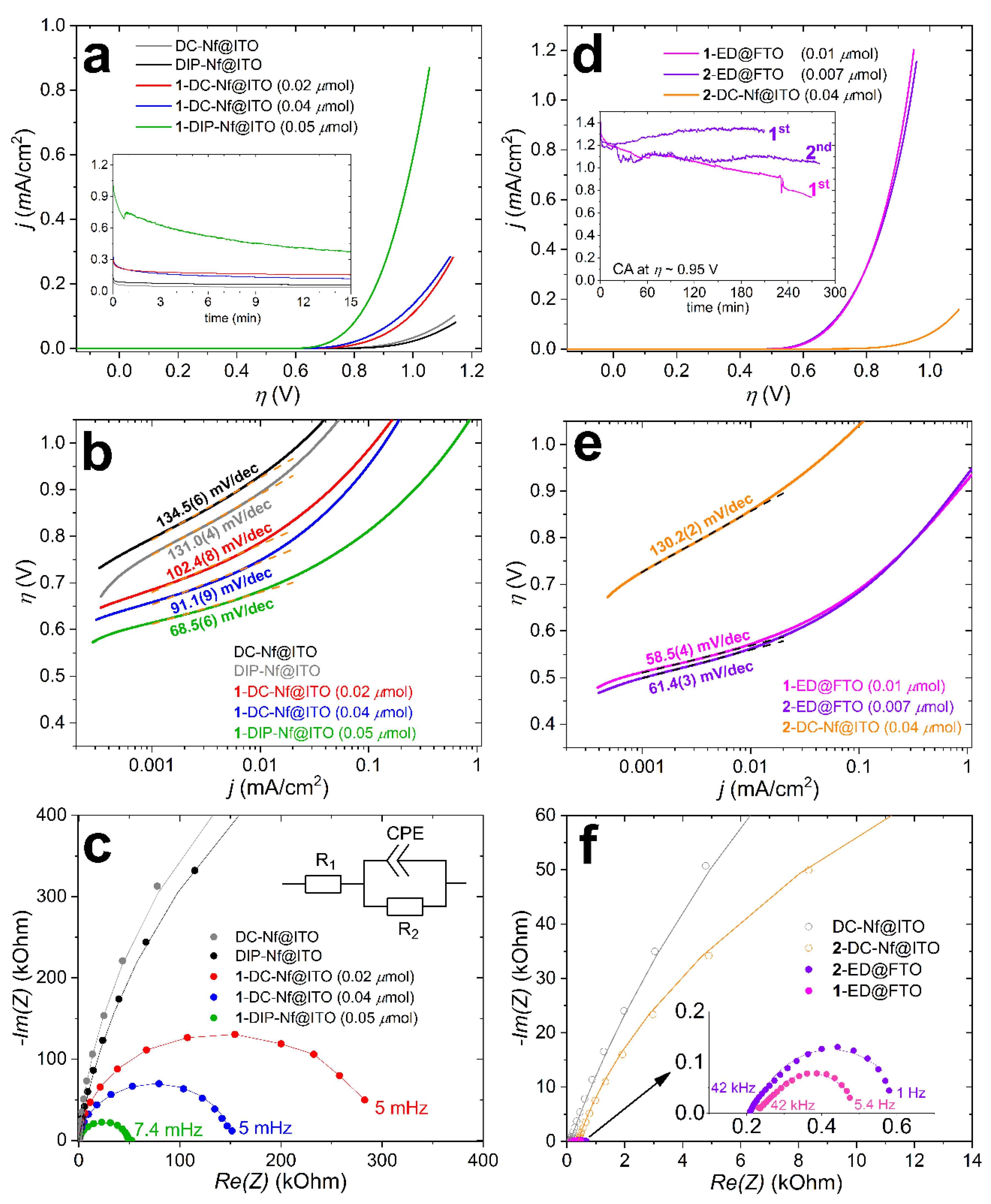
In Figure 4a, LSV curves are shown, where the current density (j, mA/cm2) is plotted against the overpotential (η = EWE − 1.23 + 0.059pH + Eref − iR, where R = R1 from EIS). It can be seen that 1-DC-Nf@ITO is less efficient in the catalysis of OER than 1-DIP-Nf@ITO, which the dip-coated electrode is utilizing 1 (the amount of adsorbed complex by DIP was calculated from the UV-vis spectroscopic analysis of the complex solution before and after the dipping, suggesting Г~ 0.05 μmol/cm2). Tafel plots were constructed from the LSVs (Figure 4b). Slopes were considered at low j to avoid un-subtracted mass-transport contribution [31]. At j > 10 μA/cm2, the slopes are drastically increased, indicating mass-transport control that may be associated with the inhomogeneous coverage of the electroactive areas by the complex and limited access of water or base to the active site. With these considerations in mind, the Tafel slope of 68.5(6) mV/dec for 1-DIP-Nf@ITO would be in tentative consistency with a single-site mechanism and limiting access of OH− to the active (BAI●)FeIV = O2+ form [25,31]. However, CA proved that the longer-term stability of this sample is rather poor, and within 15 min, the current is significantly decreased (Figure 4a, inset).
EIS was performed at an overpotential (η) of 0.67 V for all samples to evaluate the electron transfer properties near the OER onset potential for the best performing ED samples, which showed j ~0.1 mA/cm2 here, but above this current, the Tafel slopes started to increase (Figure 4e). Since this study focuses on the differences of the ED method compared to others, we adjusted the EIS potential to the ED samples. Electrodes coated with Nf only, i.e., Nf-DC@ITO, and Nf-DIP@ITO were also investigated for reference (Figure 4c). Figure 4c shows the Nyquist plot and fit of the experimental data based on a simple Randles-type equivalent circuit (see inset of Figure 4c) that reveals the smallest charge transfer resistance (R2) across the electrolyte/electrode interface for 1-DIP-Nf@ITO (Table 1). The lower onset potential observed for 1-DIP-Nf@ITO with respect to the examined DC samples is in accordance with its smallest Tafel slope and the relatively smaller R2. The n < 1 value in the CPE component indicates non-ideal behavior due to surface irregularities and complexity in the double-layer structure that is expected for such combined systems.
In sharp contrast to the previously discussed samples prepared by the DC and DIP methods, those made by electrodeposition (see Figure 3c,d), i.e., 1-ED@FTO and 2-ED@FTO, showed distinctly better performance in the OER. Moreover, this method worked equally well for both complex 1 and 2. The presence of Nf did not cause any notable differences in the OER by the thus modified electrodes; therefore, the latter combinations will not be discussed hereafter. Figure 4d shows the almost identical LSVs of 1-ED@FTO and 2-ED@FTO. A drop-casted sample, 2-DC-Nf@ITO, was also prepared by utilizing 2, despite its insolubility in methanol. The recorded LSV is shown in Figure 4d in red, in contrast to the ED samples. In this case, the LSV current, along with the other parameters in Figure 4, were identical to those of the DC-Nf@ITO that were prepared without any complex. This clearly shows that insoluble complexes are not suitable for the previously described DC method since the ligand exchange reaction to provide the catalytically active form is thorough enough only in homogeneous precursor solutions but not in a suspension.
The Tafel plot in Figure 4e reveals similar slopes for the electrodes modified by the ED method compared to that of 1-DIP-Nf@ITO (Table 1), but at lower overpotential, roughly by 0.1 V. This can be attributed to the more favorable reaction conditions for OER at the reaction centers formed by the ED method. The relatively small charge transfer resistance (R2) for the 1-ED@FTO and 2-ED@FTO are also consistent with this explanation (Figure 4f and Table 1).
Chronoamperometry (CA) with the ED samples was conducted for several hours to investigate the electrochemical stability and Faradaic efficiency. The current vs. time plots at +1.5 V vs. Ag/AgCl (η = 0.95 V) are shown as inset in Figure 4d. The complex-free Nf-DC@ITO or FTO electrodes exhibited minimal current at this potential (inset of Figure 4a). When 2-ED@FTO has been applied as the working electrode, the reaction was stopped after 3.5 h (the 1st run in the inset of Figure 4d), and a sample was taken from the headspace, and the evolved O2 gas was quantified by gas chromatography (for technical details, see our earlier publications [25,29,32]). The overall passed charge was 16.4 C; thus, the theoretical maximum for O2 was 42.4 μmol (n = Q/4F). The produced O2 was 35.2 μmol, corresponding to a Faradaic efficiency of 83% that is comparable to that found for 1 in our earlier study [25]. Based on the detected O2, the turnover number (TON) within 3.5 h of electrolysis at η = 0.95 V is over 5000, corresponding to a TOF of 0.4 s−1 that indicates good stability, especially considering the simplicity of the system. More so, since the sample could be re-used in a new buffer solution in a follow-up CA experiment for 4.5 h without a noticeable decrease in the current. Note that 1-ED@FTO containing the tia-BAI ligand (instead of the btia-BAI of 2) showed over 40% decrease of the initial current (Figure 4d, inset) that is attributed to the partial release of the complex from the surface. This underlines the advantage of the hydrophobic ligand extensions during the design of future catalytic complexes.
2.3. Post-Catalytic Analysis of the Electrodeposited Samples by SEM-EDX
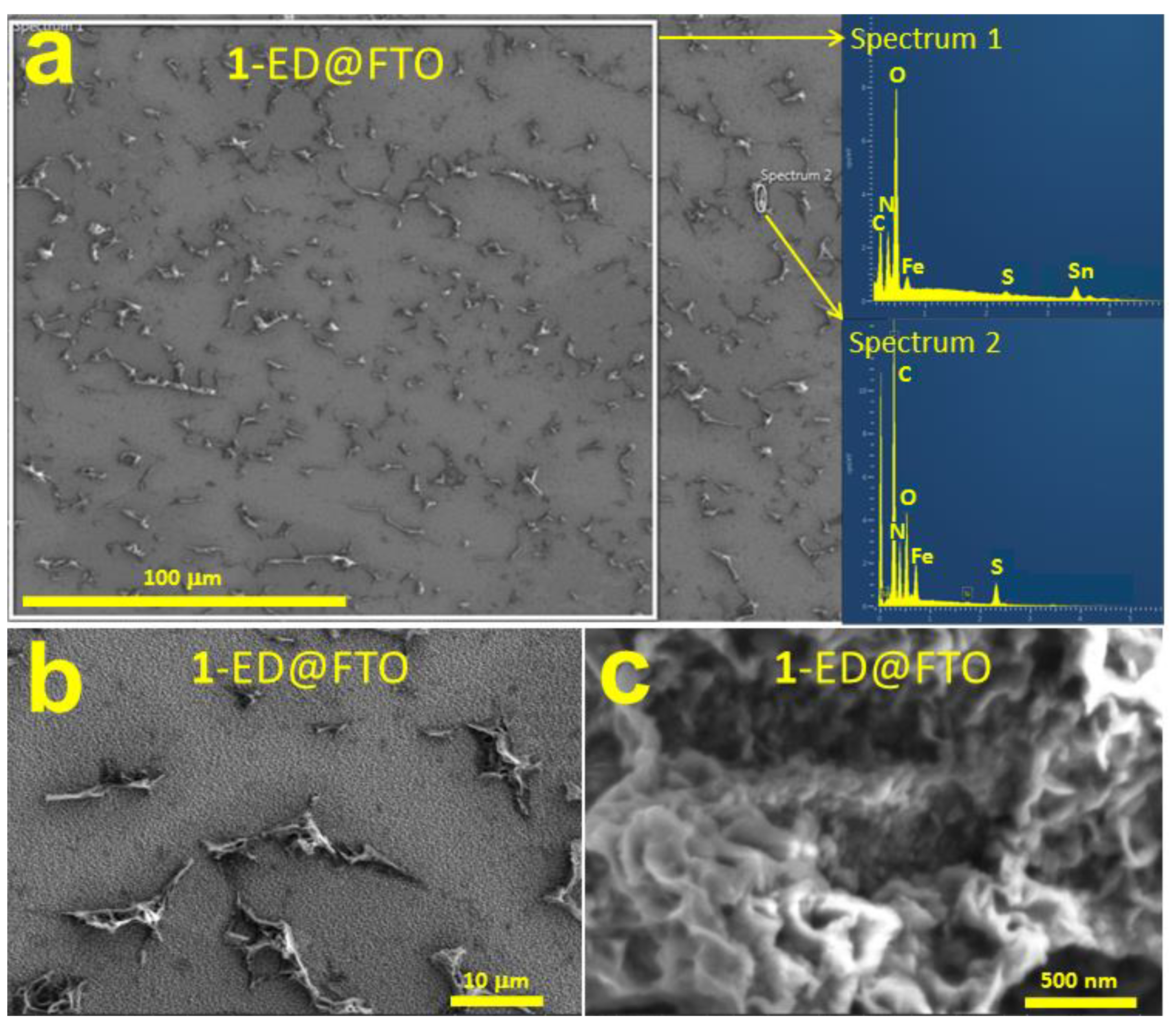
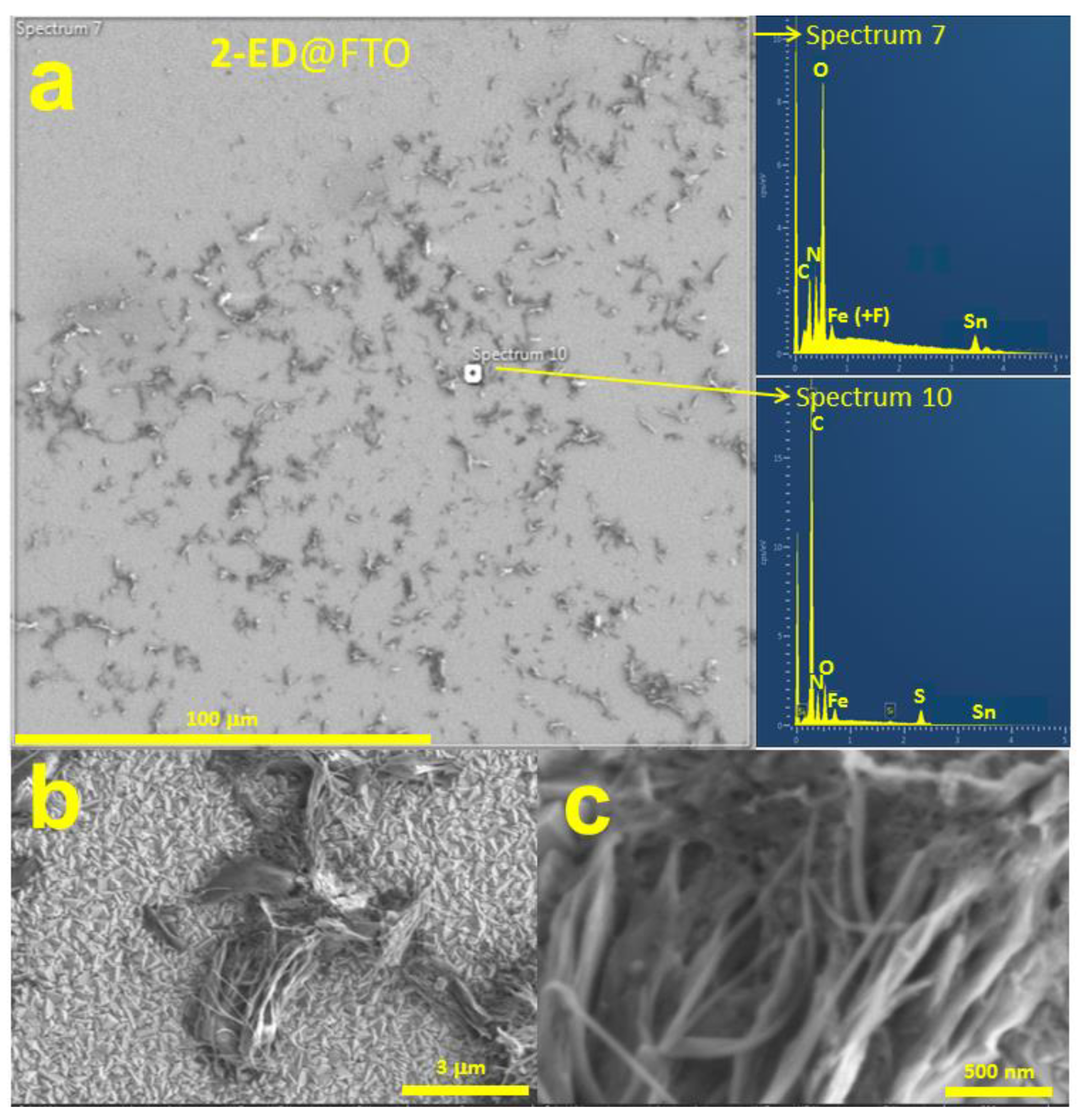
Following their use in the electrocatalytic OER experiments, the 1-ED@FTO and 2-ED@FTO electrode surfaces were investigated by scanning electron microscopy (SEM), and the elemental composition was also analyzed by energy-dispersive X-ray spectroscopy (EDX) (Figure 5a and Figure 6a). In the SEM images, it is seen that the FTO surface is covered in patches by a solid material of random morphology but in relative even distribution on a few hundred μm scale (Figure 5a and Figure 6a). The average composition by EDX confirms the presence of the expected Sn, O and F for the substrate; however, the peak of F overlaps with the Fe peak from the complex, as indicated in Spectrum 7 (EDX inset in Figure 6a). The elemental composition of complex 1 and 2 is also recognizable in the EDX spectra; however, with the remark that Cl is missing, the large, bare FTO areas suppress the C, N, Fe and S peaks, too. To gain more information about the composition and morphology of the patches, smaller areas were analyzed by SEM (Figure 5b,c and Figure 6b,c), and EDX spectra were collected of some spots (see Spectrum 2 in Figure 5a and Spectrum 10 in Figure 6a). The elemental composition at these spots suggests that the main components are C, N, S and Fe, but Cl is still absent. Note that sulfur is an important signature element in the presence of the BAI ligands. The elemental composition is thus concurring with the presence of Fe(tia-BAI) assemblies derived from 1 (the same applies to the presence of Fe(btia-BAI) assemblies in the case of 2-ED@FTO). SEM-EDX investigations on as-prepared samples revealed very similar morphological features and elemental composition to those of the used samples (Figures S3 and S4, the analogous SEM-EDX results for 1-ED@ITO and 2-ED@ITO are shown in Figure S5). Our results suggest that electrolysis does not affect majorly the morphology and the elemental composition.
Morphology analysis at larger magnification reveals differences in the fine structures for the two electrodes. In the case of 1-ED@FTO, typically coral-like deposits can be observed with a scabrous surface (Figure 5c), while the formations on the surface of 2-ED@FTO entangled fibers are seen (Figure 6c). These differences indicate that the ligand structure has a determinant role in the nanoscale structure of the electrodeposited compounds. However, one must consider the possible effect of drying on the observable morphology as the original state of the deposit can be altered due to surface tension effects associated with solvent removal (either after the ED treatment or after CA).
3. Materials and Methods
All the chemicals, solvents (dichloromethane, acetone, ethanol and methanol), Nafion, tetrabutylammonium perchlorate (TBAP) and FeCl3·6H2O were purchased from commercial sources (Sigma-Aldrich, Merck and Molar Chemicals) and used without further purification. The Fluorine-doped Tin Oxide (FTO) and Indium Tin Oxide (ITO)-coated glass slides were purchased from Ossila Ltd. (Sheffield, UK). The compounds 1,3-bis(2’-thiazolylimino)isoindoline (tia-BAIH), 1,3-bis(2’-benzothiazolylimino)isoindoline (btia-BAIH), [FeIIICl2(tia-ind)], [FeIIICl2(btia-ind)] were synthesized according to known procedures [24].
3.1. Electrochemistry in Non-Aqueous Solution
Square wave voltammetry (SWV) and cyclic voltammetry (CV) were carried out on a BioLogic SP-150 potentio/galvanostat. Complexes 1 and 2 were dissolved in dichloromethane under Ar, and water was mixed with acetone and added to the solution. Experiments were conducted using a standard three-electrode setup including a boron-doped diamond (BDD) working electrode (polished and conditioned before use), Pt auxiliary electrode and Ag+/Ag (0.01 M AgNO3, 0.1 M TBAP/acetonitrile) reference electrode. All potential values in the text and the corresponding figures are reported versus the ferrocenium/ferrocene (Fc+/Fc) redox couple. The redox potential of Fc that is Efc has been measured under the conditions of each experiment. The reported potential values are: E (V vs. Fc+/Fc) = E (V vs. Ag+/Ag)–Efc.
3.2. Drop-Casting and Dip-Coating
Method A. For drop-casting (DC), the solution was prepared by mixing Nafion with 2 mM of 1 in methanol in an ultrasonic bath for 20 min, then pipetted (3–7 μL) and layered onto the cleansed ITO or FTO by using a micro-syringe. The electrode was heated to dryness at 120 °C for 30 min.
Method B. For dip-coating (DIP), the same solution was used as in method A. The electrode was heated to dryness at 120°C for 30 min.
Method C. 5–7 µL of Nafion solution was layered onto clean ITO or FTO to give a homogeneous film (~1 cm × 1 cm), then the coated electrode was allowed to dry at 120 °C for 1 h. The electrode was immersed overnight in a 3 mM solution of complex 1 or 2 dissolved in dichloromethane in an air-tight container. The electrode was removed from the solution and dried.
3.3. Electrodeposition of Complexes 1 and 2
Method D. Electrodeposition (ED) was performed by using a three-electrode configuration, containing FTO or ITO, Pt and Ag+/Ag (0.01 M AgNO3, 0.1 M TBAP/acetonitrile), as working, counter and reference electrodes, respectively. The electrodeposition solution consisted of 0.8 mM complex 1 or 2 in dichloromethane and a mixture of 500 µL acetone and 54 µL MilliQ water. ED was conducted by a CV at a potential sweep rate of 100 mV/s, turning potentials of −0.4 V and 1.7 V vs. Fc+/Fc, for a total of 20 cycles. The surface concentration of the deposited complex was determined from the current peak integral after the final cycle by presuming a 1e− Fe(III)/Fe(II) transition (n = Q/F). The electrodes could be dried at room temperature.
3.4. Electrochemical Measurements in Aqueous Solution
All experiments were conducted in 0.2 M borate buffer (pH 8.2). Electrochemical impedance spectroscopy (EIS), linear sweep voltammetry (LSV), cyclic voltammetry (CV) and chronoamperometry (CA) were performed on a BioLogic SP-150 potentiostat. The modified FTO or ITO electrodes were set as the working electrode in a three-electrode setup (Pt auxiliary and Ag/AgCl reference). The O2 evolution was measured for a representative sample of 2@FTO prepared by method D (ED) by gas chromatography (Shimadzu GC 2010 Tracera equipped with a BID detector) of samples taken from the headspace (in the beginning, the cell was under air).
3.5. Electrochemical Impedance Spectroscopy
Electrochemical impedance spectroscopy (EIS) was performed at 1.25 V vs. Ag/AgCl to obtain the Nyquist plots. The amplitudes of the sinusoidal waves were examined as indicated in Figure 4. The curves were obtained by a Randles equivalent circuit (inset, Figure 4c) fitted to the experimental data points. This circuit has been used frequently to fit transition metal-based systems under OER conditions [33]. In the equivalent circuit R1, CPE and R2 correspond to the solution and electrode ohmic resistance, a constant phase element and the charge transfer resistance, respectively. This was the simplest model to fit reasonably well our experimental data. The fitting was carried out with the EIS Spectrum Analyser 1.0 software. CPE represents the inhomogeneity on the surface of the electrodes that causes non-ideality of the double-layer capacitance (Cdl) at the solid/electrolyte interface. In CPE, there is a pre-exponential factor (P) to represent the value of a ‘non-ideal capacity’ for CPE and the exponent (n), which is an ‘ideality factor’ ranging from 0 to 1 (ideal capacitor, where P becomes Cdl).
3.6. Physical Characterization Methods
Scanning Electron Microscopy (SEM) and energy-dispersive X-ray spectroscopy (EDX) were done for samples that were electrodeposited onto FTO. These investigations were done on a Thermo Scientific Scios2 (Waltham, MA, USA) dual-beam system equipped with an Oxford X-maxN 20 SDD EDX (Abingdon, UK), 5 keV beam energy and process time 6 were applied, dead time was below 50%. UV-visible absorption spectra were measured on an Agilent Cary 60 spectrophotometer in quartz cells. FT-IR spectra were measured on a Nicolet iS50 instrument in KBr pastilles.
4. Conclusions
Electrocatalysts for the oxygen-evolving reaction that utilize non-precious metals and efficient immobilization methods can be very useful to the progress of artificial photosynthesis and water electrolysis systems. In this work, we presented a simple electrodeposition method that allowed us to immobilize [FeIIICl2(BAI)] precursor complexes bearing aromatic NN’N pincer ligands from a suitable water/organic mixture. The process involves the loss of inner-sphere chlorides leading to the formation of the electrocatalytically active surface deposits. This method showed the advantages of drop-casting or dip-coating the [FeIIICl2(tia-BAI)] complex (1) with Nafion in terms of overpotential and better charge transfer properties. Our aim was also to reduce the amount of complex required for long-term operando stability. In the case of complex 1, this amount by electrodeposition was an order of magnitude lower compared to the self-supported system reported earlier (prepared by drop-casting of 1 from methanol without Nafion). Moreover, for [FeIIICl2(btia-BAI)] (2), which is practically insoluble in alcohols, making it unsuitable for drop-casting, the electrodeposition worked just as well, resulting in a very stable complex-electrode combination that was able to produce O2 by TON of >5000 in borate buffer at pH 8.2. The example of complex 2 with the fused aromatic rings in the ligand, aiming at water-insolubility and better surface affinity, illustrates that electrodeposition may be a fruitful immobilization method, even in the case of precursors that are only soluble in solvents that are practically immiscible with water.
Supplementary Materials
The following are available online at https://0-www-mdpi-com.brum.beds.ac.uk/article/10.3390/catal11050577/s1, Figure S1: CV scans of 1 and 2 in DCM with/no added water, Figure S2: Comparison of two parallel electrodeposition experiments using complex 1, Figure S3: SEM image of 1-ED@FTO as-prepared, Figure S4: SEM image of 2-ED@FTO as-prepared, Figure S5: SEM images and EDX spectra of 1-ED@ITO and 2-ED@ITO as-prepared, Figure S6: SEM images and EDX spectra of 1-DIP-Nf@ITO as-prepared and used in electrolysis.
Author Contributions
Conceptualization, J.S.P.; methodology, J.S.P., S.M.A.-Z. and K.F.; validation, T.B., S.M.A.-Z., Z.K. and J.S.P.; investigation, S.M.A.-Z., T.B., K.F. and J.S.P.; resources, S.M.A.-Z. and J.S.P.; data curation, Z.K. and J.S.P.; writing—original draft preparation, S.M.A.-Z. and J.S.P.; writing—review and editing, S.M.A.-Z., T.B., K.F., Z.K. and J.S.P.; visualization, S.M.A.-Z. and J.S.P.; supervision, J.S.P.; project administration, K.F. and J.S.P.; funding acquisition, J.S.P. All authors have read and agreed to the published version of the manuscript.
Funding
This research is financed by the NKFI-128841 grant and the VEKOP-2.3.2-16-2016-00011 grant supported by the European Structural and Investment Funds.
Data Availability Statement
Data is contained within the article and Supplementary Materials.
Acknowledgments
Technical support by Noémi Szász and Levente Illés in SEM-EDX is gratefully acknowledged.
Conflicts of Interest
The authors declare no conflict of interest. The funders had no role in the design of the study; in the collection, analyses, or interpretation of data; in the writing of the manuscript, or in the decision to publish the results.
References
- Lewis, N.S.; Nocera, D.G. Powering the Planet: Chemical Challenges in Solar Energy Utilization. Proc. Natl. Acad. Sci. USA 2006, 103, 15729–15735. [Google Scholar] [CrossRef] [PubMed] [Green Version]
- Chen, X.; Li, C.; Grätzel, M.; Kostecki, R.; Mao, S.S. Nanomaterials for Renewable Energy Production and Storage. Chem. Soc. Rev. 2012, 41, 7909–7937. [Google Scholar] [CrossRef] [PubMed]
- Zhang, L.-H.; Mathew, S.; Hessels, J.; Reek, J.N.H.; Yu, F. Homogeneous Catalysts Based on First-Row Transition-Metals for Electrochemical Water Oxidation. ChemSusChem 2021, 14, 235–250. [Google Scholar] [CrossRef]
- Herrero, C.; Quaranta, A.; Leibl, W.; Rutherford, A.W.; Aukauloo, A. Artificial Photosynthetic Systems. Using Light and Water to Provide Electrons and Protons for the Synthesis of a Fuel. Energy Environ. Sci. 2011, 4, 2353–2365. [Google Scholar] [CrossRef]
- Yamazaki, H.; Shouji, A.; Kajita, M.; Yagi, M. Electrocatalytic and Photocatalytic Water Oxidation to Dioxygen Based on Metal Complexes. Coord. Chem. Rev. 2010, 254, 2483–2491. [Google Scholar] [CrossRef]
- Kärkäs, M.D.; Verho, O.; Johnston, E.V.; Åkermark, B. Artificial Photosynthesis: Molecular Systems for Catalytic Water Oxidation. Chem. Rev. 2014, 114, 11863–12001. [Google Scholar] [CrossRef]
- Zhang, B.; Sun, L. Artificial Photosynthesis: Opportunities and Challenges of Molecular Catalysts. Chem. Soc. Rev. 2019, 48, 2216–2264. [Google Scholar] [CrossRef] [Green Version]
- McCrory, C.C.; Jung, S.; Peters, J.C.; Jaramillo, T.F. Benchmarking Heterogeneous Electrocatalysts for the Oxygen Evolution Reaction. J. Am. Chem. Soc. 2013, 135, 16977–16987. [Google Scholar] [CrossRef]
- Wang, J.-W.; Hou, C.; Huang, H.-H.; Liu, W.-J.; Ke, Z.-F.; Lu, T.-B. Further Insight into the Electrocatalytic Water Oxidation by Macrocyclic Nickel(II) Complexes: The Influence of Steric Effect on Catalytic Activity. Catal. Sci. Technol. 2017, 7, 5585–5593. [Google Scholar] [CrossRef]
- Zhang, L.-H.; Yu, F.; Shi, Y.; Li, F.; Li, H. Base-Enhanced Electrochemical Water Oxidation by a Nickel Complex in Neutral Aqueous Solution. Chem. Commun. 2019, 55, 6122–6125. [Google Scholar] [CrossRef]
- Lukács, D.; Szyrwiel, Ł.; Pap, J.S. Copper Containing Molecular Systems in Electrocatalytic Water Oxidation—Trends and Perspectives. Catalysts 2019, 9, 83. [Google Scholar] [CrossRef] [Green Version]
- Liu, S.; Lei, Y.-J.; Xin, Z.-J.; Lu, Y.-B.; Wang, H.-Y. Water Splitting Based on Homogeneous Copper Molecular Catalysts. J. Photochem. Photobiol. A Chem. 2018, 355, 141–151. [Google Scholar] [CrossRef]
- Dogutan, D.K.; McGuire, R.; Nocera, D.G. Electocatalytic Water Oxidation by Cobalt(III) Hangman β-Octafluoro Corroles. J. Am. Chem. Soc. 2011, 133, 9178–9180. [Google Scholar] [CrossRef] [PubMed]
- Sun, H.; Han, Y.; Lei, H.; Chen, M.; Cao, R. Cobalt Corroles with Phosphonic Acid Pendants as Catalysts for Oxygen and Hydrogen Evolution from Neutral Aqueous Solution. Chem. Commun. 2017, 53, 6195–6198. [Google Scholar] [CrossRef]
- Zhou, F.; Izgorodin, A.; Hocking, R.K.; Spiccia, L.; MacFarlane, D.R. Electrodeposited MnOx Films from Ionic Liquid for Electrocatalytic Water Oxidation. Adv. Energy Mater. 2012, 2, 1013–1021. [Google Scholar] [CrossRef]
- Hernández, S.; Ottone, C.; Varetti, S.; Fontana, M.; Pugliese, D.; Saracco, G.; Bonelli, B.; Armandi, M. Spin-Coated vs. Electrodeposited Mn Oxide Films as Water Oxidation Catalysts. Materials 2016, 9, 296. [Google Scholar] [CrossRef] [Green Version]
- Bang, S.; Lee, Y.-M.; Hong, S.; Cho, K.-B.; Nishida, Y.; Seo, M.S.; Sarangi, R.; Fukuzumi, S.; Nam, W. Redox-Inactive Metal Ions Modulate the Reactivity and Oxygen Release of Mononuclear Non-Haem Iron(III)–Peroxo Complexes. Nat. Chem. 2014, 6, 934–940. [Google Scholar] [CrossRef] [Green Version]
- Yan, Z.; Liu, H.; Hao, Z.; Yu, M.; Chen, X.; Chen, J. Electrodeposition of (Hydro)Oxides for an Oxygen Evolution Electrode. Chem. Sci. 2020, 11, 10614–10625. [Google Scholar] [CrossRef] [Green Version]
- Zhang, K.; Yan, Z.; Chen, J. Electrodeposition Accelerates Metal-Based Batteries. Joule 2020, 4, 10–11. [Google Scholar] [CrossRef]
- Therese, G.H.A.; Kamath, P.V. Electrochemical Synthesis of Metal Oxides and Hydroxides. Chem. Mater. 2000, 12, 1195–1204. [Google Scholar] [CrossRef]
- Iwami, H.; Okamura, M.; Kondo, M.; Masaoka, S. Electrochemical Polymerization Provides a Function-Integrated System for Water Oxidation. Angew. Chem. Int. Ed. 2021, 60, 5965–5969. [Google Scholar] [CrossRef]
- Dharmadasa, I.M.; Haigh, J. Strengths and Advantages of Electrodeposition as a Semiconductor Growth Technique for Applications in Macroelectronic Devices. J. Electrochem. Soc. 2005, 153, G47. [Google Scholar] [CrossRef]
- Roger, I.; Symes, M.D. First Row Transition Metal Catalysts for Solar-Driven Water Oxidation Produced by Electrodeposition. J. Mater. Chem. A 2016, 4, 6724–6741. [Google Scholar] [CrossRef] [Green Version]
- Váradi, T.; Pap, J.S.; Giorgi, M.; Párkányi, L.; Csay, T.; Speier, G.; Kaizer, J. Iron(III) Complexes with Meridional Ligands as Functional Models of Intradiol-Cleaving Catechol Dioxygenases. Inorg. Chem. 2013, 52, 1559–1569. [Google Scholar] [CrossRef]
- Al-Zuraiji, S.M.; Lukács, D.; Németh, M.; Frey, K.; Benkó, T.; Illés, L.; Pap, J.S. An Iron(III) Complex with Pincer Ligand—Catalytic Water Oxidation through Controllable Ligand Exchange. Reactions 2020, 1, 16–36. [Google Scholar] [CrossRef]
- Kripli, B.; Baráth, G.; Balogh-Hergovich, É.; Giorgi, M.; Simaan, A.J.; Párkányi, L.; Pap, J.S.; Kaizer, J.; Speier, G. Correlation between the SOD-like Activity of Hexacoordinate Iron(II) Complexes and Their Fe3+/Fe2+ Redox Potentials. Inorg. Chem. Commun. 2011, 14, 205–209. [Google Scholar] [CrossRef]
- Martić, G.; Engle, J.T.; Ziegler, C.J. Complexes of 1,3-Bis(2-Thiazolylimino)Isoindoline with Middle and Late First Row Transition Metals. Inorg. Chem. Commun. 2011, 14, 1749–1752. [Google Scholar] [CrossRef]
- Meder, M.B.; Gade, L.H. Coordination Chemistry of 1,3-Bis(2-Pyridylimino)- and 1,3-Bis(2-Thiazolylimino)Soindole Copper Complexes: Investigation of Their Catalytic Behavior in Oxidation Reactions. Eur. J. Inorg. Chem. 2004, 2004, 2716–2722. [Google Scholar] [CrossRef]
- Al-Zuraiji, S.M.; Benkó, T.; Illés, L.; Németh, M.; Frey, K.; Sulyok, A.; Pap, J.S. Utilization of Hydrophobic Ligands for Water-Insoluble Fe(II) Water Oxidation Catalysts—Immobilization and Characterization. J. Catal. 2020, 381, 615–625. [Google Scholar] [CrossRef]
- Csonka, R.; Speier, G.; Kaizer, J. Isoindoline-Derived Ligands and Applications. RSC Adv. 2015, 5, 18401–18419. [Google Scholar] [CrossRef]
- Shinagawa, T.; Garcia-Esparza, A.T.; Takanabe, K. Insight on Tafel Slopes from a Microkinetic Analysis of Aqueous Electrocatalysis for Energy Conversion. Sci. Rep. 2015, 5, 13801. [Google Scholar] [CrossRef] [PubMed] [Green Version]
- Lukács, D.; Németh, M.; Szyrwiel, Ł.; Illés, L.; Pécz, B.; Shen, S.; Pap, J.S. Behavior of a Cu-Peptide Complex under Water Oxidation Conditions—Molecular Electrocatalyst or Precursor to Nanostructured CuO Films? Sol. Energy Mater. Sol. Cells 2019, 201, 110079. [Google Scholar] [CrossRef]
- Beltrán-Suito, R.; Forstner, V.; Hausmann, J.N.; Mebs, S.; Schmidt, J.; Zaharieva, I.; Laun, K.; Zebger, I.; Dau, H.; Menezes, P.W.; et al. A Soft Molecular 2Fe–2As Precursor Approach to the Synthesis of Nanostructured FeAs for Efficient Electrocatalytic Water Oxidation. Chem. Sci. 2020, 11, 11834–11842. [Google Scholar] [CrossRef]
Scheme 1.
Structure of the BAI− complexes used in this work.

Figure 1.
Schematic presentation of the different deposition methods applied in this study.

Figure 2.
(a) UV-visible absorption spectra of 1 and 2 in dry DCM, the wavelengths for the characteristic ILCT bands are given with numbers; (b) FTIR spectra of 1 and 2 as solid dispersed in KBr pastille.
Figure 2.
(a) UV-visible absorption spectra of 1 and 2 in dry DCM, the wavelengths for the characteristic ILCT bands are given with numbers; (b) FTIR spectra of 1 and 2 as solid dispersed in KBr pastille.

Figure 3.
(a) CV scans of 1 (0.4 mM) in dry DCM (in blue) or with added H2O (in red, 3 mmol H2O in 0.5 mL acetone) on a BDD electrode (0.071 cm2); (b) CV scans of 2 (0.4 mM) under the same conditions as those in (a), inset: SWV showing the potentials of the redox transitions in the two different media; (c) CV scans of complex 1 (0.8 mM) on FTO (1.5 cm2) in DCM with added water (3 mmol of H2O in 0.5 mL acetone, see also the ED method); (d) CV scans of complex 2 (0.8 mM) under the same conditions as those in (c). Settings: under Ar, ν = 100 mV/s, 20 cycles (red CVs), Pt and Ag+/Ag (0.01 M AgNO3, 0.1 M TBAP/acetonitrile), as counter and reference electrodes, respectively.

Figure 4.
(a) LSVs (ν = 5 mV/s) and inset: chronoamperometry (CA) currents at +1.5 V vs. AgCl/Ag, (b) Tafel plot constructed from LSV, and (c) Nyquist plot of EIS data (symbols, frequency range from 200 kHz to as indicated) and fitted equivalent circuits (lines) for complex 1 immobilized by the DC and DIP methods (Figure 1) on ITO, and data for the complex-free electrodes for comparison. Inset in (c) equivalent circuit for the fitting of the experimental impedance data, R1 corresponds to the solution + electrode ohmic resistance, R2 is the charge transfer resistance, and CPE is a constant phase element consisting of a pre-exponential factor P and an exponent (inhomogeneity factor) n; (d) LSVs of complexes 1 and 2 immobilized by the ED method and compared to complex 2 on ITO immobilized by the DC method. Inset in (d) CA for the same samples at +1.5 V vs. AgCl/Ag, 1st and 2nd runs for 2-ED@FTO show two consecutive tests with the same electrode; (e) Tafel plots, and (f) Nyquist plot of EIS data (symbols) and fitted equivalent circuits (lines) for the same samples as those in (e). Conditions: all measurements were done in 0.2 M borate buffer at pH 8.2, Pt auxiliary and AgCl/Ag reference electrodes (more details in experimental section).

Figure 5.
(a) SEM image at ×500 magnification of 1-ED@FTO after 4.5 h of CA at +1.5 V vs. Ag/AgCl in 0.2 M borate buffer at pH 8.2, inset: EDX spectrum of the area in the white frame ((Spectrum 1), and from a small spot (Spectrum 2)); (b) SEM images at ×2000; and (c) at ×50,000 magnification (see Figure 1 and Figure 3c for further information on this sample).

Figure 6.
(a) SEM image at ×500 magnification of 2-ED@FTO after 8 h of CA at +1.5 V vs. Ag/AgCl in 0.2 M borate buffer at pH 8.2, inset: EDX spectrum of the area in the white frame ((Spectrum 7, and from a small spot (Spectrum 10)); (b) SEM image at ×10,000; and (c) at ×50,000 magnification (see Figure 1 and Figure 3d for further information on this sample).


Table 1.
Tafel slopes and fitting parameters of the equivalent circuit to the experimental EIS data.
Table 1.
Tafel slopes and fitting parameters of the equivalent circuit to the experimental EIS data.
| Sample | Tafel Slope (mV/dec) | R1 (Ω) | R2 (Ω) | P (μFs(1−n)) a | nb |
|---|---|---|---|---|---|
| 1-DC-Nf@ITO (0.02 μmol) | 102.4(8) | 61.6(13) | 291(13) × 103 | 19.9(4) | 0.947(5) |
| 1-DC-Nf@ITO (0.04 μmol) | 91.1(9) | 96.4(8) | 151(4) × 103 | 19.3(3) | 0.952(5) |
| 1-DIP-Nf@ITO | 68.5(6) | 121.1(18) | 51(2) × 103 | 16.0(4) | 0.909(5) |
| 1-ED@FTO | 58.5(4) | 242.5(3) | 259.5(8) | 122.7(6) | 0.691(8) |
| 2-ED@FTO | 61.4(3) | 211.7(3) | 426.5(12) | 86.5(3) | 0.676(7) |
| 2-DC-Nf@ITO (0.04 μmol) | 130.2(2) | 388.6(7) | 53(9) × 103 | 21.3(2) | 0.964(10) |
a Pre-exponential factor P represents a ‘non-ideal capacity’ for CPE. b ‘Ideality factor’ ranging from 0 to 1. For details, see the corresponding paragraph in Section 3.
Publisher’s Note: MDPI stays neutral with regard to jurisdictional claims in published maps and institutional affiliations. |
© 2021 by the authors. Licensee MDPI, Basel, Switzerland. This article is an open access article distributed under the terms and conditions of the Creative Commons Attribution (CC BY) license (https://creativecommons.org/licenses/by/4.0/).
Share and Cite
MDPI and ACS Style
Al-Zuraiji, S.M.; Benkó, T.; Frey, K.; Kerner, Z.; Pap, J.S. Electrodeposition of Fe-Complexes on Oxide Surfaces for Efficient OER Catalysis. Catalysts 2021, 11, 577. https://0-doi-org.brum.beds.ac.uk/10.3390/catal11050577
AMA Style
Al-Zuraiji SM, Benkó T, Frey K, Kerner Z, Pap JS. Electrodeposition of Fe-Complexes on Oxide Surfaces for Efficient OER Catalysis. Catalysts. 2021; 11(5):577. https://0-doi-org.brum.beds.ac.uk/10.3390/catal11050577
Chicago/Turabian StyleAl-Zuraiji, Sahir M., Tímea Benkó, Krisztina Frey, Zsolt Kerner, and József S. Pap. 2021. "Electrodeposition of Fe-Complexes on Oxide Surfaces for Efficient OER Catalysis" Catalysts 11, no. 5: 577. https://0-doi-org.brum.beds.ac.uk/10.3390/catal11050577
Note that from the first issue of 2016, this journal uses article numbers instead of page numbers. See further details here.