
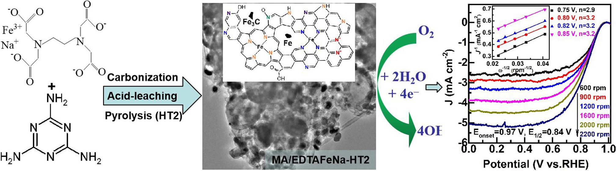
Electrocatalysis for Oxygen Reduction Reaction on EDTAFeNa and Melamine co-Derived Self-Supported Fe-N-C Materials

Abstract
:
1. Introduction
2. Results and Discussion
3. Materials and Methods
3.1. Materials
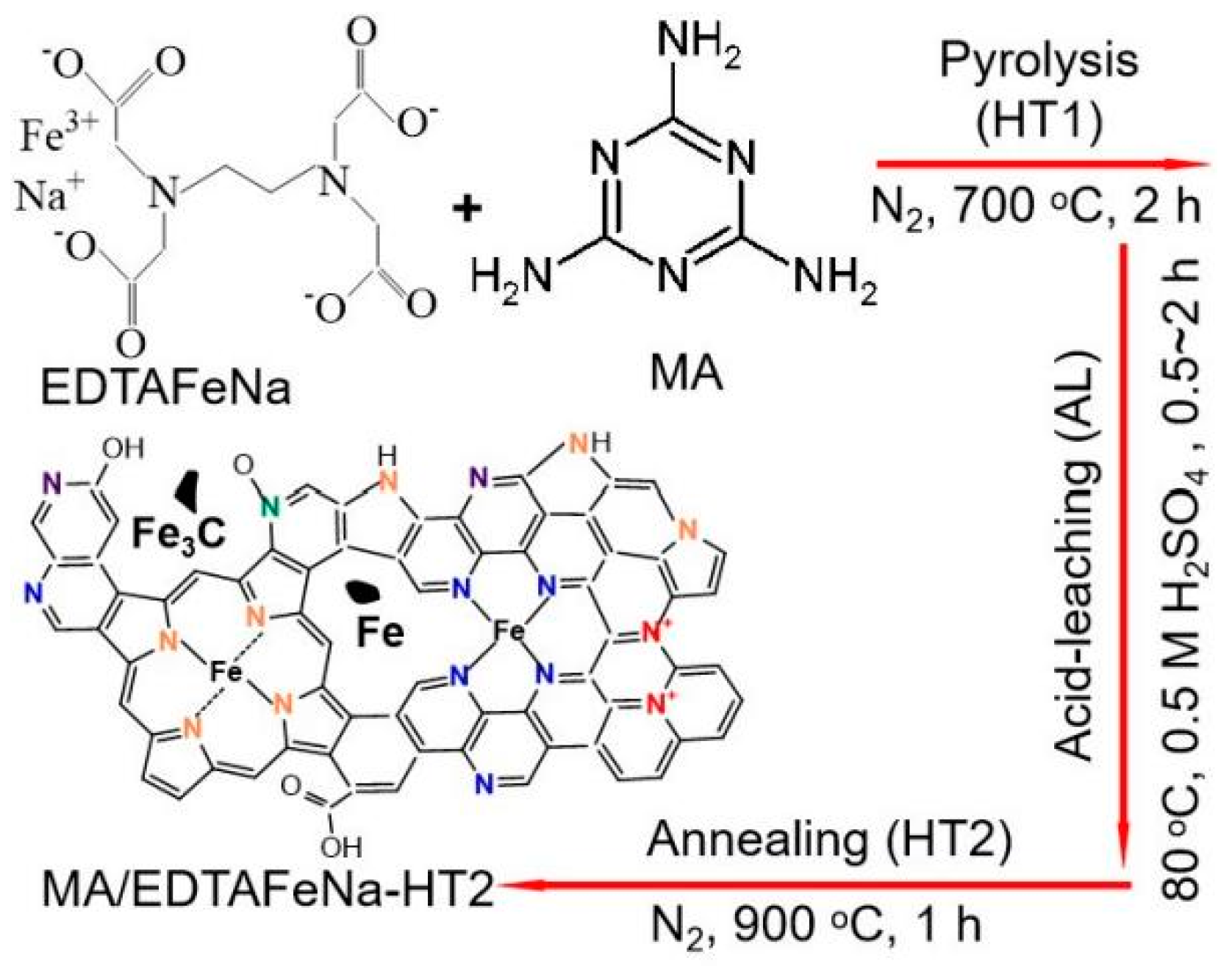
3.2. Catalyst Preparation
3.3. Characterization of Catalysts
3.4. Electrochemical Measurements
4. Conclusions
Supplementary Materials
Author Contributions
Funding
Acknowledgments
Conflicts of Interest
References
- Yan, X.-H.; Prabhu, P.; Xu, H.; Meng, Z.; Xue, T.; Lee, J.M. Recent progress of metal carbides encapsulated in carbon-based materials for electrocatalysis of oxygen reduction reaction. Small Methods 2020, 4, 1900575. [Google Scholar] [CrossRef]
- Zhang, G.-R.; Wöllner, S. Hollowed structured PtNi bifunctional electrocatalyst with record low total overpotential for oxygen reduction and oxygen evolution reactions. Appl. Catal. B Environ. 2018, 222, 26–34. [Google Scholar] [CrossRef]
- Fu, G.; Tang, Y.; Lee, J.M. Recent advances in carbon-based bifunctional oxygen electrocatalysts for Zn-air batteries. ChemElectroChem 2018, 5, 1424–1434. [Google Scholar] [CrossRef]
- Fu, G.; Lee, J.-M. Ternary metal sulfides for electrocatalytic energy conversion. J. Mater. Chem. A 2019, 7, 9386–9405. [Google Scholar] [CrossRef]
- Jaouen, F.; Proietti, E.; Lefèvre, M.; Chenitz, R.; Dodelet, J.-P.; Wu, G.; Chung, H.T.; Johnston, C.M.; Zelenay, P. Recent advances in non-precious metal catalysis for oxygen-reduction reaction in polymer electrolyte fuel cells. Energy Environ. Sci. 2011, 4, 114–130. [Google Scholar] [CrossRef]
- Yan, X.-H.; Xu, B.-Q. Mesoporous carbon material co-doped with nitrogen and iron (Fe-N-C): High-performance cathode catalyst for oxygen reduction reaction in alkaline electrolyte. J. Mater. Chem. A 2014, 2, 8617–8622. [Google Scholar] [CrossRef]
- Zhang, H.; Hwang, S.; Wang, M.; Feng, Z.; Karakalos, S.; Luo, L.; Qiao, Z.; Xie, X.; Wang, C.; Su, D.; et al. Single atomic iron catalysts for oxygen reduction in acidic media: Particle size control and thermal activation. J. Am. Chem. Soc. 2017, 139, 14143–14149. [Google Scholar] [CrossRef]
- Hu, Y.; Jensen, J.O.; Zhang, W.; Cleemann, L.N.; Xing, W.; Bjerrum, N.J.; Li, Q. Hollow spheres of iron carbide nanoparticles encased in graphitic layers as oxygen reduction catalysts. Angew. Chem. Int. Ed. 2014, 53, 3675–3679. [Google Scholar] [CrossRef]
- Liu, K.; Peng, Z.; Wang, H.; Ren, Y.; Liu, D.; Li, J.; Tang, Y.; Zhang, N. Fe3C@Fe/N doped graphene-like carbon sheets as a highly efficient catalyst in Al-air batteries. J. Electrochem. Soc. 2017, 164, F475–F483. [Google Scholar] [CrossRef]
- Tang, F.; Lei, H.; Wang, S.; Wang, H.; Jin, Z. A novel Fe-N-C catalyst for efficient oxygen reduction reaction based on polydopamine nanotubes. Nanoscale 2017, 9, 17364–17370. [Google Scholar] [CrossRef] [Green Version]
- Kicinski, W.; Dembinska, B.; Norek, M.; Budner, B.; Polanski, M.; Kulesza, P.J.; Dyjak, S. Heterogeneous iron-containing carbon gels as catalysts for oxygen electroreduction: Multifunctional role of sulfur in the formation of efficient systems. Carbon 2017, 116, 655–669. [Google Scholar] [CrossRef]
- Gokhale, R.; Chen, Y.; Serov, A.; Artyushkova, K.; Atanassov, P. Direct synthesis of platinum group metal-free Fe-N-C catalyst for oxygen reduction reaction in alkaline media. Electrochem. Commun. 2016, 72, 140–143. [Google Scholar] [CrossRef] [Green Version]
- Yan, X.-H.; Meng, Z.; Xu, H.; Xue, T.; Fang, G.; Hu, Z. Synthesis of Fe-C-N hybrid via direct pyrolysis of EDTA ferric sodium as effective electrocatalyst for oxygen reduction reaction. Int. J. Electrochem. Sci. 2019, 14, 6938–6947. [Google Scholar] [CrossRef]
- Sun, M.; Davenport, D.; Liu, H.; Qu, J.; Elimelech, M.; Li, J. Highly efficient and sustainable non-precious-metal Fe-N-C electrocatalysts for the oxygen reduction reaction. J. Mater. Chem. A 2018, 6, 2527–2539. [Google Scholar] [CrossRef]
- Chen, Z.; Higgins, D.; Yu, A.; Zhang, L.; Zhang, J. A review on non-precious metal electrocatalysts for PEM fuel cells. Energy Environ. Sci. 2011, 4, 3167–3192. [Google Scholar] [CrossRef]
- Fu, X.; Li, N.; Ren, B.; Jiang, G.; Liu, Y.; Hassan, F.M.; Su, D.; Zhu, J.; Yang, L.; Bai, Z. Fuel cells: tailoring FeN4 sites with edge enrichment for boosted oxygen reduction performance in proton exchange membrane fuel cell. Adv. Energy Mater. 2019, 9, 1970031. [Google Scholar] [CrossRef] [Green Version]
- Zitolo, A.; Goellner, V.; Armel, V.; Sougrati, M.-T.; Mineva, T.; Stievano, L.; Fonda, E.; Jaouen, F. Identification of catalytic sites for oxygen reduction in iron-and nitrogen-doped graphene materials. Nat. Mater. 2015, 14, 937. [Google Scholar] [CrossRef] [PubMed]
- Zhang, Z.; Sun, J.; Wang, F.; Dai, L. Efficient oxygen reduction reaction (ORR) catalysts based on single iron atoms dispersed on a hierarchically structured porous carbon framework. Angew. Chem. Int. Ed. 2018, 57, 9038–9043. [Google Scholar] [CrossRef] [PubMed]
- Wu, G.; More, K.L.; Johnston, C.M.; Zelenay, P. High-performance electrocatalysts for oxygen reduction derived from polyaniline, iron, and cobalt. Science 2011, 332, 443–447. [Google Scholar] [CrossRef] [Green Version]
- Guan, B.; Yu, L.; Lou, X. A dual-metal-organic-framework derived electrocatalyst for oxygen reduction. Energy Environ. Sci. 2016, 9, 3092–3096. [Google Scholar] [CrossRef]
- Wang, D.; Xiao, L.; Yang, P.; Xu, Z.; Lu, X.; Du, L.; Levin, O.; Ge, L.; Pan, X.; Zhang, J.; et al. Dual-nitrogen-source engineered Fe-Nx moieties as a booster for oxygen electroreduction. J. Mater. Chem. A 2019, 7, 11007–11015. [Google Scholar] [CrossRef]
- Wang, H.; Yin, F.-X.; Liu, N.; Kou, R.-H.; He, X.-B.; Sun, C.-J.; Chen, B.-H.; Liu, D.-J.; Yin, H.Q. Engineering Fe-Fe3C@ Fe-N-C active sites and hybrid structures from dual metal-organic frameworks for oxygen reduction reaction in H2-O2 fuel cell and Li-O2 battery. Adv. Funct. Mater. 2019, 29, 1901531. [Google Scholar] [CrossRef]
- Xu, X.; Xia, Z.; Zhang, X.; Sun, R.; Sun, X.; Li, H.; Wu, C.; Wang, J.; Wang, S.; Sun, G. Atomically dispersed Fe-N-C derived from dual metal-organic frameworks as efficient oxygen reduction electrocatalysts in direct methanol fuel cells. Appl. Catal. B Environ. 2019, 259, 118042. [Google Scholar] [CrossRef]
- Chung, H.T.; Cullen, D.A.; Higgins, D.; Sneed, B.T.; Holby, E.F.; More, K.L.; Zelenay, P. Direct atomic-level insight into the active sites of a high-performance PGM-free ORR catalyst. Science 2017, 357, 479–484. [Google Scholar] [CrossRef] [Green Version]
- Peng, H.; Hou, S.; Dang, D.; Zhang, B.; Liu, F.; Zheng, R.; Luo, F.; Song, H.; Huang, P.; Liao, S. Ultra-high-performance doped carbon catalyst derived from o-phenylenediamine and the probable roles of Fe and melamine. Appl. Catal. B Environ. 2014, 158, 60–69. [Google Scholar] [CrossRef]
- Koslowski, U.I.; Abs-Wurmbach, I.; Fiechter, S.; Bogdanoff, P. Nature of the catalytic centers of porphyrin-based electrocatalysts for the ORR: A correlation of kinetic current density with the site density of Fe-N4 centers. J. Phys. Chem. C 2008, 112, 15356–15366. [Google Scholar] [CrossRef]
- Gong, K.; Du, F.; Xia, Z.; Durstock, M.; Dai, L. Nitrogen-doped carbon nanotube arrays with high electrocatalytic activity for oxygen reduction. Science 2009, 323, 760–764. [Google Scholar] [CrossRef] [Green Version]
- Guo, D.; Shibuya, R.; Akiba, C.; Saji, S.; Kondo, T.; Nakamura, J. Active sites of nitrogen-doped carbon materials for oxygen reduction reaction clarified using model catalysts. Science 2016, 351, 361–365. [Google Scholar] [CrossRef]
- Deng, H.; Li, X.; Peng, Q.; Wang, X.; Chen, J.; Li, Y. Monodisperse magnetic single-crystal ferrite microspheres. Angew. Chem. Int. Ed. 2005, 44, 2782–2785. [Google Scholar] [CrossRef]
- Wen, Z.; Ci, S.; Zhang, F.; Feng, X.; Cui, S.; Mao, S.; Luo, S.; He, Z.; Chen, J. Nitrogen-enriched core-shell structured Fe/Fe3C-C nanorods as advanced electrocatalysts for oxygen reduction reaction. Adv. Mater. 2012, 11, 1399–1404. [Google Scholar] [CrossRef] [PubMed]
- Yan, X.-H.; Xue, P. Tailoring magnetic mesoporous silica spheres immobilized lipase for kinetic resolution of methyl 2-bromopropionate in co-solvent system. Res. Chem. Intermed. 2018, 44, 4295–4306. [Google Scholar] [CrossRef]
- Yuan, S.; Shui, J.L.; Grabstanowicz, L.; Chen, C.; Commet, S.; Reprogle, B.; Xu, T.; Yu, L.; Liu, D.-J. A highly active and support-free oxygen reduction catalyst prepared from ultrahigh-surface-area porous polyporphyrin. Angew. Chem. Int. Ed. 2013, 52, 8349–8353. [Google Scholar] [CrossRef]
- Sa, Y.J.; Woo, J.; Joo, S.H. Strategies for enhancing the electrocatalytic activity of M-N/C catalysts for the oxygen reduction reaction. Top. Catal. 2018, 61, 1077–1100. [Google Scholar] [CrossRef]
- Ferrari, A.; Meyer, J.C.; Scardaci, V.; Casiraghi, C.; Lazzeri, M.; Mauri, F.; Piscanec, S.; Jiang, D.; Novoselov, K.S.; Roth, S. Raman spectrum of graphene and graphene layers. Phys. Rev. Lett. 2006, 97, 187401. [Google Scholar] [CrossRef] [PubMed] [Green Version]
- Wu, G.; Johnston, C.M.; Mack, N.H.; Artyushkova, K.; Ferrandon, M.; Nelson, M.; Lezama-Pacheco, J.S.; Conradson, S.D.; More, K.L.; Myers, D.J.; et al. Synthesis-structure-performance correlation for polyaniline-Me-C non-precious metal cathode catalysts for oxygen reduction in fuel cells. J. Mater. Chem. 2011, 21, 11392–11405. [Google Scholar] [CrossRef]
- Qie, L.; Chen, W.; Xu, H.; Xiong, X.; Jiang, Y.; Zou, F.; Hu, X.; Xin, Y.; Zhang, Z.; Huang, Y. Synthesis of functionalized 3D hierarchical porous carbon for high-performance supercapacitors. Energy Environ. Sci. 2013, 6, 2497–2504. [Google Scholar] [CrossRef]
- Chang, Z.-W.; Meng, F.-L.; Zhong, H.-X.; Zhang, X.-B. Anchoring iron-EDTA complex on graphene toward the synthesis of highly efficient Fe-N-C oxygen reduction electrocatalyst for fuel cells. Chin. J. Chem. 2018, 36, 287–293. [Google Scholar] [CrossRef]
- Yan, X.-H.; Meng, Z.; Prabhu, P.; Xu, H.; Xue, T.; Fang, G.; Lee, J.-M. Self-supported Fe-N-C electrocatalyst via pyrolysis of EDTAFeNa adsorbed on SBA-15 for the oxygen reduction reaction. Ind. Eng. Chem. Res. 2020, 59, 3016–3023. [Google Scholar] [CrossRef]
- Kramm, U.I.; Herrmann-Geppert, I.; Behrends, J.; Lips, K.; Fiechter, S.; Bogdanoff, P. On an easy way to prepare metal-nitrogen doped carbon with exclusive presence of MeN4-type sites active for the ORR. J. Am. Chem. Soc. 2016, 138, 635–640. [Google Scholar] [CrossRef] [PubMed]
- Hou, C.; Zou, L.; Sun, L.; Zhang, K.; Liu, Z.; Li, Y.; Li, C.; Zou, R.; Yu, J.; Xu, Q. Single-atom iron catalysts on overhang-eave carbon cages for high-performance oxygen reduction reaction. Angew. Chem. Int. Ed. 2020, 59, 7384–7389. [Google Scholar] [CrossRef]
- Jin, X.; Xie, Y.; Huang, J. Highly effective dual transition metal macrocycle based electrocatalyst with macro-/mesoporous structures for oxygen reduction reaction. Catalysts 2017, 7, 201. [Google Scholar] [CrossRef]
- Lefevre, M.; Proietti, E.; Jaouen, F.; Dodelet, J.P. Iron-based catalysts with improved oxygen reduction activity in polymer electrolyte fuel cells. Science 2009, 324, 71–74. [Google Scholar] [CrossRef]
- Bard, A.J.; Faulkner, L.R. Electrochemical Methods: Fundamentals and Applications, 2nd ed.; John Wiley & Sons: New York, NY, USA, 2001; pp. 339–343. [Google Scholar]
- Treimer, S.; Tanga, A.; Johnson, D.C. A consideration of the application of koutecky-levich plots in the diagnoses of charge-transfer mechanisms at rotated disk electrodes. Electroanalysis 2002, 14, 165–171. [Google Scholar] [CrossRef]
- Choi, C.H.; Choi, W.S.; Kasian, O.; Mechler, A.K.; Sougrati, M.T.; Bruller, S.; Strickland, K.; Jia, Q.; Mukerjee, S.; Mayrhofer, K.J.J.; et al. Unraveling the nature of sites active toward hydrogen peroxide reduction in Fe-N-C catalysts. Angew. Chem. Int. Ed. 2017, 56, 8809–8812. [Google Scholar] [CrossRef] [PubMed] [Green Version]
- Holewinski, A.; Linicz, S. Elementary mechanisms in electrocatalysis: Revisiting the ORR Tafel slope. J. Electrochem. Soc. 2012, 159, H864–H870. [Google Scholar] [CrossRef]


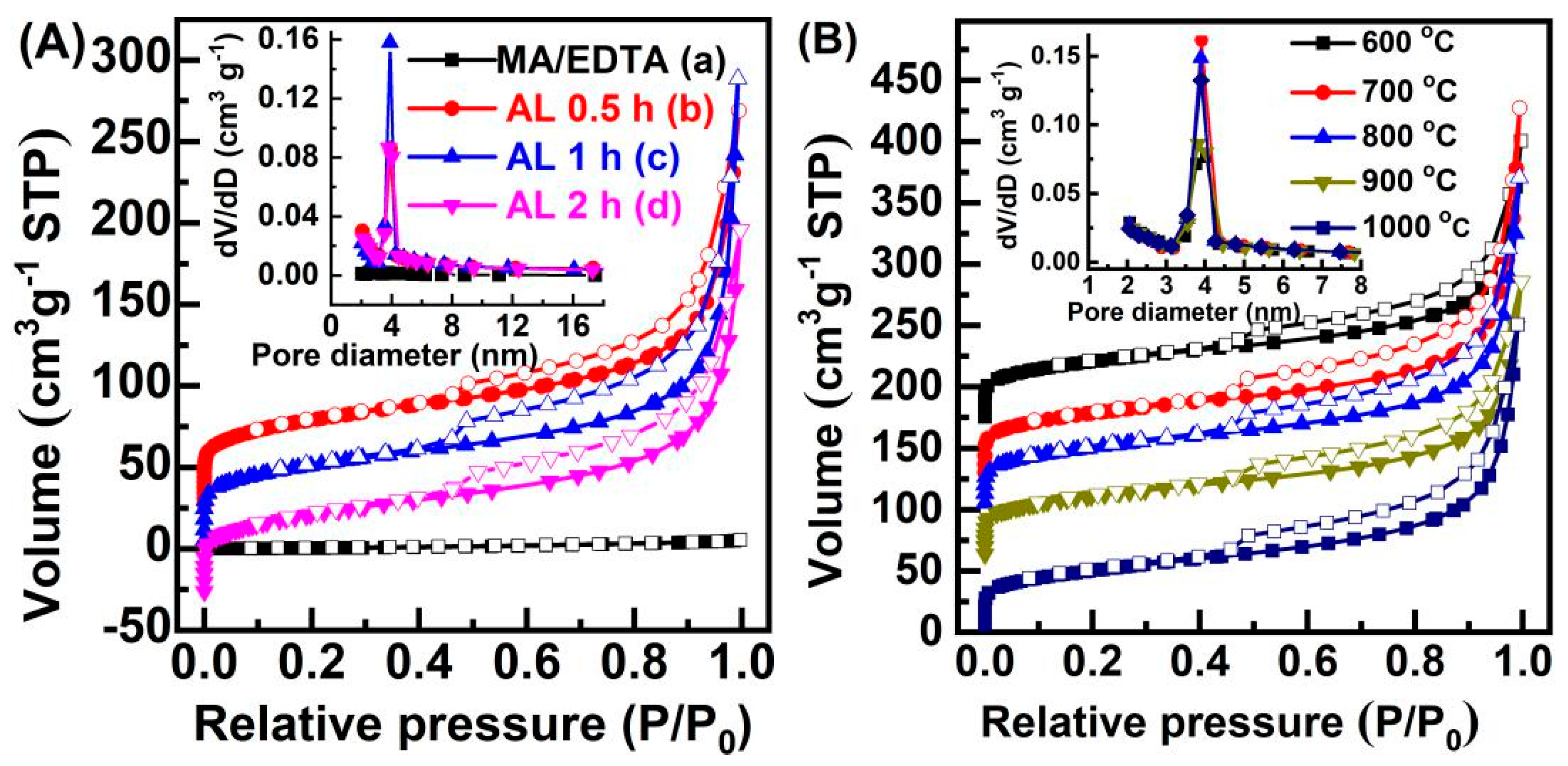
| Sample | Dp (nm) | V (cm3 g−1) | SBET (m2 g−1) |
|---|---|---|---|
| MA/EDTA-HT2 | 3.8 | 0.01 | 4 |
| MA/EDTAFeNa-HT2 (A 0.5 h) | 3.9 | 0.36 | 196 |
| MA/EDTAFeNa-HT2 (AL 1 h) | 3.9 | 0.44 | 239 |
| MA/EDTAFeNa-HT2 (AL 2 h) | 3.8 | 0.33 | 180 |
| MA/EDTAFeNa-HT2 (600 °C) | 4.0 | 0.34 | 182 |
| MA/EDTAFeNa-HT2 (700 °C) | 3.9 | 0.46 | 255 |
| MA/EDTAFeNa-HT2 (800 °C) | 3.9 | 0.42 | 227 |
| MA/EDTAFeNa-HT2 (1000 °C) | 3.9 | 0.39 | 207 |
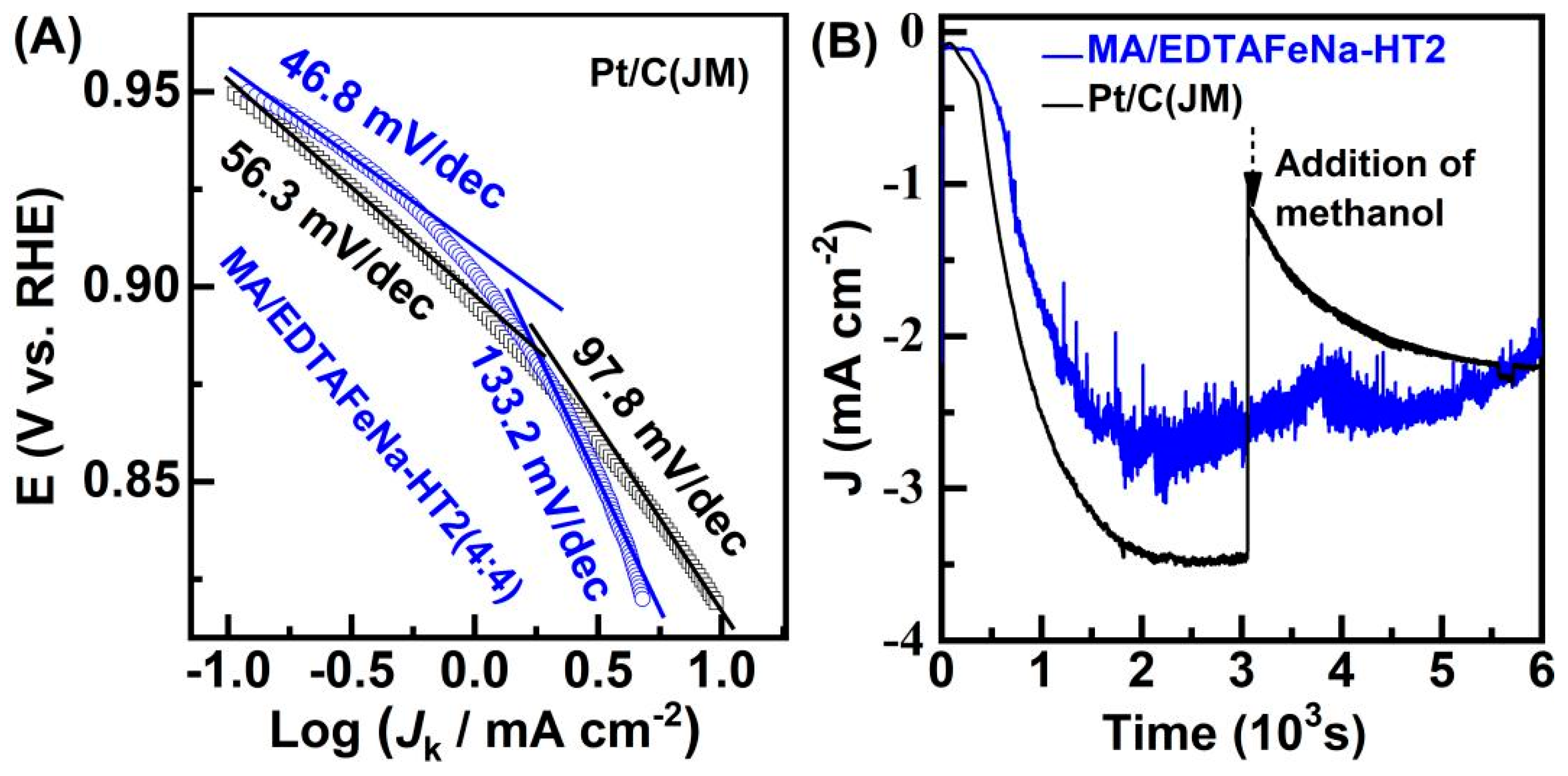
| Simple | Eonset (V) | E1/2 (V) | JL (mA cm−2) | Jk (mA cm−2) | |
|---|---|---|---|---|---|
| 0.85 V | 0.87 V | ||||
| MA/EDTA-HT2 (a) | 0.71 | 0.49 | 1.51 | - | - |
| MA/EDTAFeNa-HT2 (b) | 0.95 | 0.79 | 3.94 | 1.40 | 0.93 |
| MA/EDTAFeNa-HT2 (c) | 0.96 | 0.83 | 3.81 | 2.20 | 1.23 |
| MA/EDTAFeNa-HT2 (d) | 0.96 | 0.82 | 4.45 | 2.20 | 1.22 |
| MA/EDTAFeNa-HT2 (e) | 0.97 | 0.81 | 3.37 | 1.68 | 1.10 |
| MA/EDTAFeNa-HT2 (f) | 0.98 | 0.83 | 3.43 | 2.21 | 1.40 |
| MA/EDTAFeNa-HT2 (g) | 0.98 | 0.84 | 3.94 | 3.26 | 2.27 |
| Pt/C (JM, 20 wt.% Pt) (h) | 0.97 | 0.84 | 5.92 | 4.48 | 2.31 |
| EDTAFeNa-HT2 | 0.93 | 0.79 | 4.58 | 0.95 | 0.49 |
Publisher’s Note: MDPI stays neutral with regard to jurisdictional claims in published maps and institutional affiliations. |
© 2021 by the authors. Licensee MDPI, Basel, Switzerland. This article is an open access article distributed under the terms and conditions of the Creative Commons Attribution (CC BY) license (https://creativecommons.org/licenses/by/4.0/).
Share and Cite
Shen, M.; Meng, Z.; Xue, T.; Shen, H.; Yan, X.-H. Electrocatalysis for Oxygen Reduction Reaction on EDTAFeNa and Melamine co-Derived Self-Supported Fe-N-C Materials. Catalysts 2021, 11, 623. https://0-doi-org.brum.beds.ac.uk/10.3390/catal11050623
Shen M, Meng Z, Xue T, Shen H, Yan X-H. Electrocatalysis for Oxygen Reduction Reaction on EDTAFeNa and Melamine co-Derived Self-Supported Fe-N-C Materials. Catalysts. 2021; 11(5):623. https://0-doi-org.brum.beds.ac.uk/10.3390/catal11050623
Chicago/Turabian StyleShen, Mengfan, Ziwei Meng, Tong Xue, Hongfang Shen, and Xiang-Hui Yan. 2021. "Electrocatalysis for Oxygen Reduction Reaction on EDTAFeNa and Melamine co-Derived Self-Supported Fe-N-C Materials" Catalysts 11, no. 5: 623. https://0-doi-org.brum.beds.ac.uk/10.3390/catal11050623