Article

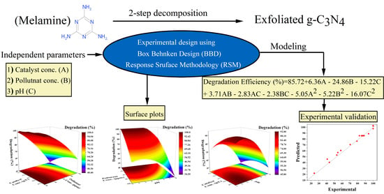
Analysis of Photocatalytic Degradation of Phenol with Exfoliated Graphitic Carbon Nitride and Light-Emitting Diodes Using Response Surface Methodology

by
Adeem Ghaffar Rana
1,2 and
Mirjana Minceva
1,*
1
Biothermodynamics, TUM School of Life Sciences, Technical University of Munich, Maximus-von-Imhof-Forum 2, 85354 Freising, Germany
2
Department of Chemical, Polymer, and Composite Materials Engineering, University of Engineering and Technology (UET), Lahore 39161, Pakistan
*
Author to whom correspondence should be addressed.
Submission received: 2 July 2021 / Revised: 22 July 2021 / Accepted: 23 July 2021 / Published: 25 July 2021

Abstract

:
Response surface methodology (RSM) involving a Box–Benkhen design (BBD) was employed to analyze the photocatalytic degradation of phenol using exfoliated graphitic carbon nitride (g-C3N4) and light-emitting diodes (wavelength = 430 nm). The interaction between three parameters, namely, catalyst concentration (0.25–0.75 g/L), pollutant concentration (20–100 ppm), and pH of the solution (3–10), was examined and modeled. An empirical regression quadratic model was developed to relate the phenol degradation efficiency with these three parameters. Analysis of variance (ANOVA) was then applied to examine the significance of the model; this showed that the model is significant with an insignificant lack of fit and an R2 of 0.96. The statistical analysis demonstrated that, in the studied range, phenol concentration considerably affected phenol degradation. The RSM model shows a significant correlation between predicted and experimental values of photocatalytic degradation of phenol. The model’s accuracy was tested for 50 ppm of phenol under optimal conditions involving a catalyst concentration of 0.4 g/L catalysts and a solution pH of 6.5. The model predicted a degradation efficiency of 88.62%, whereas the experimentally achieved efficiency was 83.75%.

Graphical Abstract

1. Introduction

For all living beings, water is considered to be the most important resource. Easy access to clean water is one of the biggest challenges for mankind. In the last few decades, advancements in science, technology, and industrialization have led to considerable benefits to mankind but at the cost of a more polluted environment, particularly water [1]. There are multiple categories of pollutants in water, such as heavy metals, dyes, pesticides, pharmaceuticals, and other organic pollutants. Amongst organic pollutants, phenolic compounds, with ~3 million tons of global production, are an emerging contaminant detected in water [1,2,3,4].
Phenols or phenolics are essential because of their wide range of applications in the processing and manufacturing industry. However, the ecosystem’s contamination by phenolics is concerning because of the adverse implications on human health such as their endocrine-disrupting abilities and carcinogenic behavior [1,5,6]. Moreover, these chemicals cause environmental issues such as water hardness, pH change, and a decrease in dissolved oxygen level. Furthermore, the Environmental Protection Agency (EPA) and the European Union (EU) have included a few phenols in their priority pollutants list. It is necessary to make this polluted water containing phenols and other pollutants suitable for human use and aquatic life using certain techniques to minimize the usage of these chemicals [5].
The removal of phenolic compounds from wastewater has attracted considerable attention from researchers [5]. Many biological, chemical, and physical techniques such as membrane filtration, coagulation–flocculation, adsorption [7,8], ion exchange, bacterial and fungal biosorption [9], aerobic and anaerobic processes [10] are used for phenol removal. In these processes, there are many constraints such as high cost, and low efficiency; furthermore, these methods do not completely remove phenol from wastewater [11,12]. Moreover, using these techniques, phenol is transferred from wastewater to a solid phase that requires treatment for safe disposal, which leads to additional cost for the whole process. Thus, it is necessary to develop an alternative effective and cost-efficient method for phenol removal from wastewater.
Advanced oxidative processes (AOP) are successful for achieving the complete removal of pollutants [13]. The degradation process using AOP can be performed in several ways, such as using only oxidizing agents, light irradiance in addition with oxidizing agents, and photocatalysis [14]. For all these processes, the degradation process is conducted using OH radicals that are generated during the oxidation reaction. Among these processes, photocatalysis has attracted considerable interest because it can harvest solar light with the help of semiconductor materials (catalysts). The catalysts can help solve environmental issues related to water contaminations; these semiconductor materials are nontoxic and efficient. Note that different semiconductor materials such as ZnO [15], TiO2 [16], SiO2, Al2O3 [8], and g-C3N4 [17,18], are used for environmental applications in photocatalysis; these have considerable advantages because of the large surface areas, adsorption capacities, and better absorption of light. Among these materials, g-C3N4 offers improved visible light absorption [17,19,20,21].
g-C3N4, a polymeric semiconductor, composed of C, N, and H, has gained considerable interest from researchers for novel generation of photocatalysts because of its widespread catalytic uses in oxidation and reduction processes, such as pollutant degradation, water splitting, and CO2 reduction. These materials have been extensively used for environmental remediation because they are easy to synthesize, metal-free, inexpensive, and easily available [22,23,24]. Furthermore, g-C3N4 possesses higher thermal and chemical stability because of π-conjugated frameworks connecting the 2D layered structure of tri-s-triazine building blocks. g-C3N4 can be activated by visible light of 420–460 nm because of its low bandgap energy (2.7 eV) [25,26]. There are, however, certain challenges associated with the application of g-C3N4 in phenol removal such as low surface area, fast recombination rate, and low conductivity, thus resulting in lower efficiency. To overcome these limitations, multiple strategies have been used to improve the surface electronic structures and activity of the bulk g-C3N4 in visible light. To improve the activity of pristine g-C3N4, strategies such as metal and non-metal doping, exfoliation, hard and soft templating, and metal oxide heterojunctions have been used [27,28,29,30,31].
Factors affecting the removal efficiency can be tuned by the morphology and/or chemistry of the catalyst and by optimizing the operating parameters. Multiple operating parameters play an important role in the photocatalytic degradation process, thus making their optimization important for achieving good photocatalytic degradation of the target pollutant. Response surface methodology (RSM) is one of the most commonly applied optimization techniques; it is a powerful optimization tool for an experimental design that efficiently helps in systemic analysis [5,11,14]. RSM uses mathematics and statistics to analyze the relative significance of influencing factors on the response of the studied system. RSM is suitable for predicting the effect of individual experimental operating parameters, in addition to locating interactions between parameters and their impact on a response variable. RSM uses a systematic technique to simultaneously vary all parameters and evaluate the influence of these parameters on photocatalytic degradation [32,33]. The greatest advantage of RSM lies in the systematic approach for the experimental design, which mostly requires fewer experiments, thus reducing the time required and thereby being more economical. For designing these experiments, a central composite design (CCD) [3] and Box–Benkhen design (BBD) [11,12] are most commonly used. For the same number of parameters, BBD requires fewer experiments than CCD [3]; therefore, in this study, BBD is selected as a preferred design approach.
The objective of this study was to analyze the photocatalytic degradation of phenol with metal-free g-C3N4 and visible LED light and to model the process using RSM. In this study, the operating parameters considered were catalyst concentration, phenol concentration, and pH of the solution. BBD was used for the experimental design and RSM was applied to determine the mathematical relationship between operating parameters and phenol degradation. Finally, the correlation determined by RSM was experimentally validated.

2. Materials and Methods

2.1. Chemicals and Materials

Melamine (C3H6N6, 99%) was purchased from Alfa Aesar. Phenol (C6H5OH, 99%) was purchased from Merck. Acetonitrile (C2H3N, 99.99%) and ultra-pure water for high-performance liquid chromatography (HPLC) were purchased from Sigma Aldrich. NaOH and HCl were purchased from VWR chemicals. All chemicals used were of analytical grade and used as-received without any further purification.

2.2. Photocatalyst Synthesis

Photocatalyst was prepared as per the procedure used in our previous study [18]; the synthesis process is briefly reported here. Melamine was placed in a muffle furnace (Carbolite Gero, GPC 1200, Derbyshire, UK) in a closed crucible to prepare bulk g-C3N4 using thermal decomposition. The synthesis process comprised two steps: A heating ramp rate of 2 °C min−1 was programmed up to 450 °C; this temperature was maintained for 2 h. Then, the temperature was increased to 550 °C using a heating ramp rate of 2 °C min−1 and then maintained for 4 h. The material synthesized was crushed in mortar after cooling, then rinsed with ultrapure water, and dried overnight at 80 °C. The exfoliation process was conducted in an open crucible at 500 °C for 2 h at a heating ramp rate of 2 °C min−1 in a muffle furnace.

2.3. Characterization of the Photocatalyst

Fourier transform infrared (FTIR) measurements (4000–400 cm−1) were performed on a Spectrum Two FT-IR Spectrometer (PerkinElmer, Switzerland) with a universal ATR (UATR Two) cell equipped with a ZnSe single crystal. The acquisition performed using 60 scans and the resolution was set to 4 cm−1. Zetasizer Nano ZEN5600 (Malvern, UK) was used to measure the zeta potential of the synthesized material. SU8030 (Hitachi, Japan) SEM-type microscope operated at an acceleration voltage of 10 kV and a probe current of 15 pA was used to examine the morphology of the material with scanning electron microscopy (SEM).

2.4. RSM with Box–Behnken Experimental Design

The influence of three independent operating parameters, i.e., catalyst concentration (A), phenol initial concentration (B), and pH of the solution (C), was considered in RSM. The remaining reaction conditions, namely, the airflow rate (50 mL/min) and reaction time (3 h), was kept constant in the experiment based on previous study [18]. The degradation efficiency of phenol (Equation (1)) was set as a response variable. Note that a previous study [18] was conducted to obtain the upper and lower limits of the parameters. Table 1 shows the ranges and levels of independent parameters A, B, and C. BBD was used to examine the combined effect of these three variables. Section 3.3 lists the set of experiments in table; it includes a replication of experiments at the central point. Regression analysis was the performed using OriginPro 2021 9.8.0.200 (OriginLab Corporation, Northampton, MA, USA) software. The suggested model’s data were analyzed for significance and suitability using analysis for variance (ANOVA).

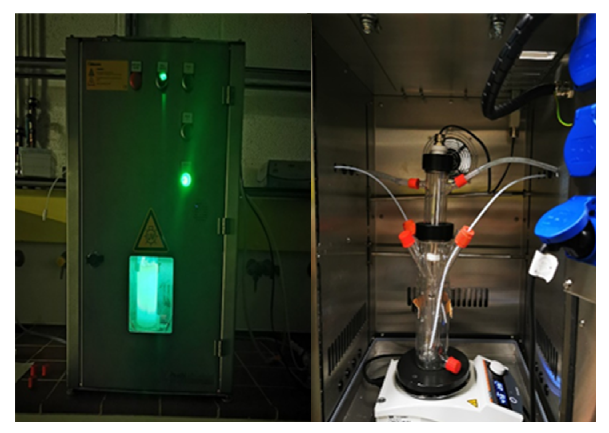
2.5. Photocatalytic Experiments

Figure 1 shows the photocatalytic experiments that were conducted in a jacketed glass reactor (working volume 225 mL) (Peschl Ultraviolet GmbH, Mainz, Germany) with a safety cabinet. The reactor was irradiated from inside using a custom-made LED immersion lamp; the LED has maximum emission at 430 nm. Glass reactor was then sonicated with a reaction mixture for uniform dispersion, followed by stirring with continuous airflow to maintain adsorption–desorption equilibrium for 30 min. Subsequently, lights were turned on, which is considered as zero time (to). Nine to ten samples (1 mL) were periodically collected from the reaction mixture. After centrifugation and filtration, the samples were analyzed using HPLC. For acidic and basic reaction conditions, the pH of the mixture was adjusted using 0.1 M HCl and NaOH. The phenol degradation efficiency was determined using the following Equation:
D e g r a d a t i o n   e f f i c i e n c y   ( % ) = C o C C o × 100
where C o is the initial phenol concentration and C is the residual phenol concentration in the solution at an irradiation time t.
The reduction of the reaction mixture volume due to the sampling was less than 5% at the end of the experiments and was therefore not considered in the calculation of the phenol degradation efficiency.

2.6. Analytical Techniques

A prominence HPLC system from Shimadzu (Kyoto, Japan) was used for analyzing the samples obtained from the reactor. The system is equipped with a binary pump (Model LC-20AB), an autosampler (Model SIL-20A), a degasser (Model DGU-20A3,) and a diode-array detector (Model SPD-M20A). Phenomenex (C18, 150 × 4.6 mm, 3 µm) column was used with a fixed flow rate of 0.8 mL/min, with the mobile phase gradient of water (A) and acetonitrile (B): starts with 15% B, followed by 60% B in 7 min and back to 15% B in 8 min; injection of 5 μL; UV light of 254 nm. Phenol was analyzed at a maximum absorption wavelength (λmax) of 270 nm.

3. Results and Discussion

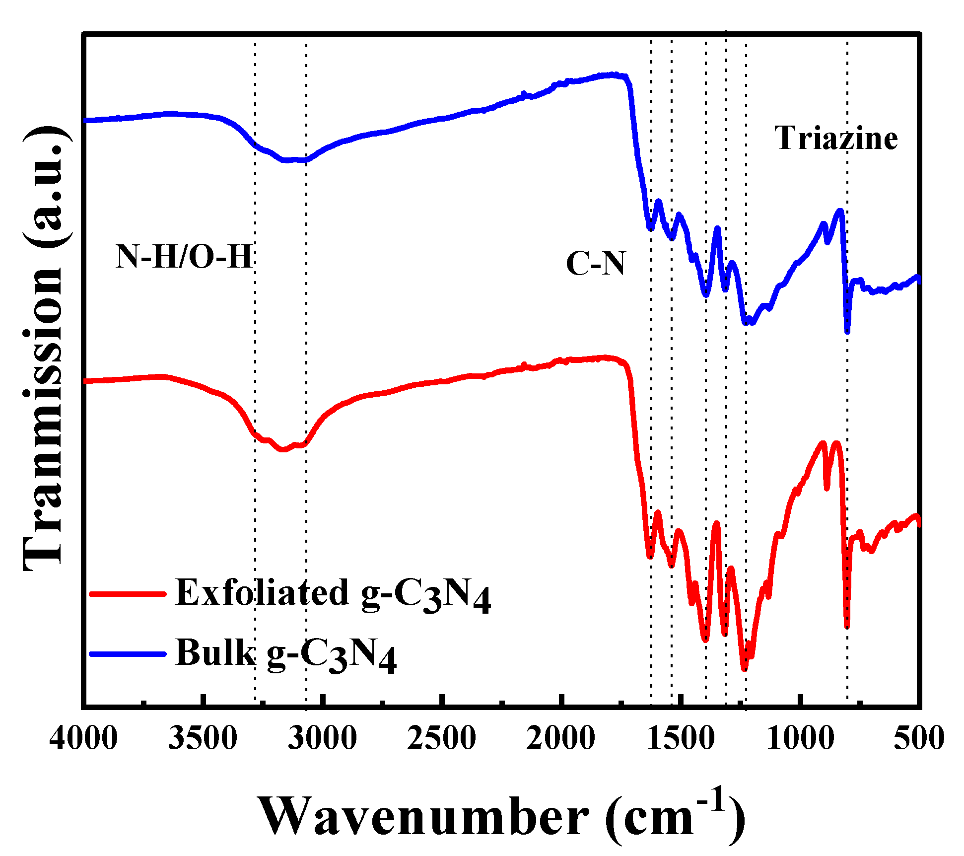
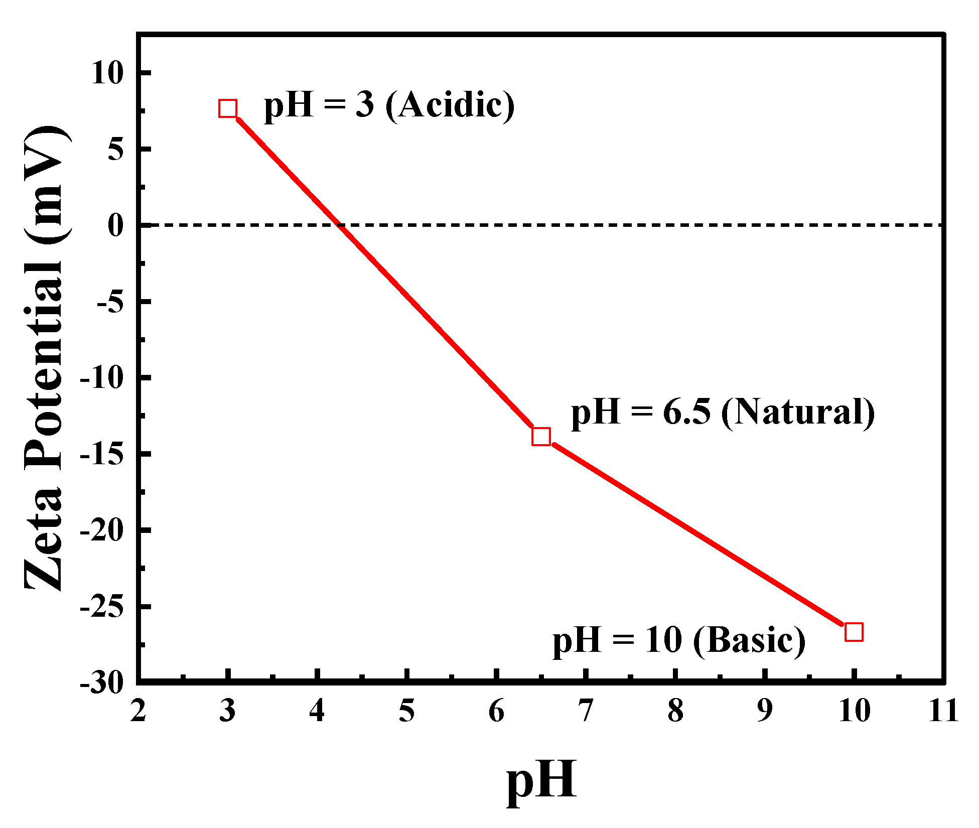
3.1. Photocatalyst Characterization

The metal-free g-C3N4 used in this study was synthesized and characterized in our previous study [18] using transmission electron microscopy (TEM), Brunauer–Emmett–Teller isotherms (BET), X-ray diffraction (XRD), X-ray photoelectron spectroscopy (XPS), photoluminescence (PL), and UV-Vis spectroscopy. In this study, scanning electron microscopy (SEM), Fourier transform infrared spectroscopy (FTIR), and zeta potential analyses were performed. Table 2 lists the physical properties of metal-free g-C3N4 before and after its exfoliation.
The exfoliated material has a significantly higher surface area than the bulk material, while the average pore size of both materials is almost the same (Table 2 and Figure S1). Using XRD, the material shows two characteristic peaks of g-C3N4 (Figure S4) [34,35]. The strong and weak peaks of N1s and C1s observed in XPS confirm the chemical state of g-C3N4 (Figure S3) [17,36,37,38,39,40,41]. Table 2 lists the maximum absorption wavelength and bandgap of the material, which are presented in Figure S2 [42,43].
In Figure 2, the selected SEM images of bulk and exfoliated g-C3N4 are presented. The thermal exfoliation transformed the stacked and aggregated structure of bulk g-C3N4 in a porous nanosheet structure. The reduction in layer thickness (Figure 2b) leads to an increase in the specific surface area of g-C3N4 [17,44,45,46].
Figure 3 shows the catalysts’ FTIR spectra. A broad peak is observed between 3200 and 3000 cm−1, which can be attributed to the stretching vibrations of N–H bonds from residual amino groups and adsorbed H2O. The sharp peak that appears at 806 cm−1 can be attributed to the breathing mode of triazine units [47,48], whereas the strong bands between 1636 and 1242 cm−1 belong to the C=N and C–N bonds of heterocyclic rings. Because the spectra of both materials show the same absorption bands, the chemical structure remained unaltered after treatment.
Figure 4 shows the effect of pH on the zeta potential of the exfoliated g-C3N4. The catalyst surface is positively charged at acidic pH (3) and negatively charged at natural (6) and basic pH (10).
The optical properties (PL/UV-Vis) and surface area (BET) of the material have changed with exfoliation; however, the chemical state (XPS), phase (XRD), and the chemical structure (FTIR) remained the same after exfoliation.

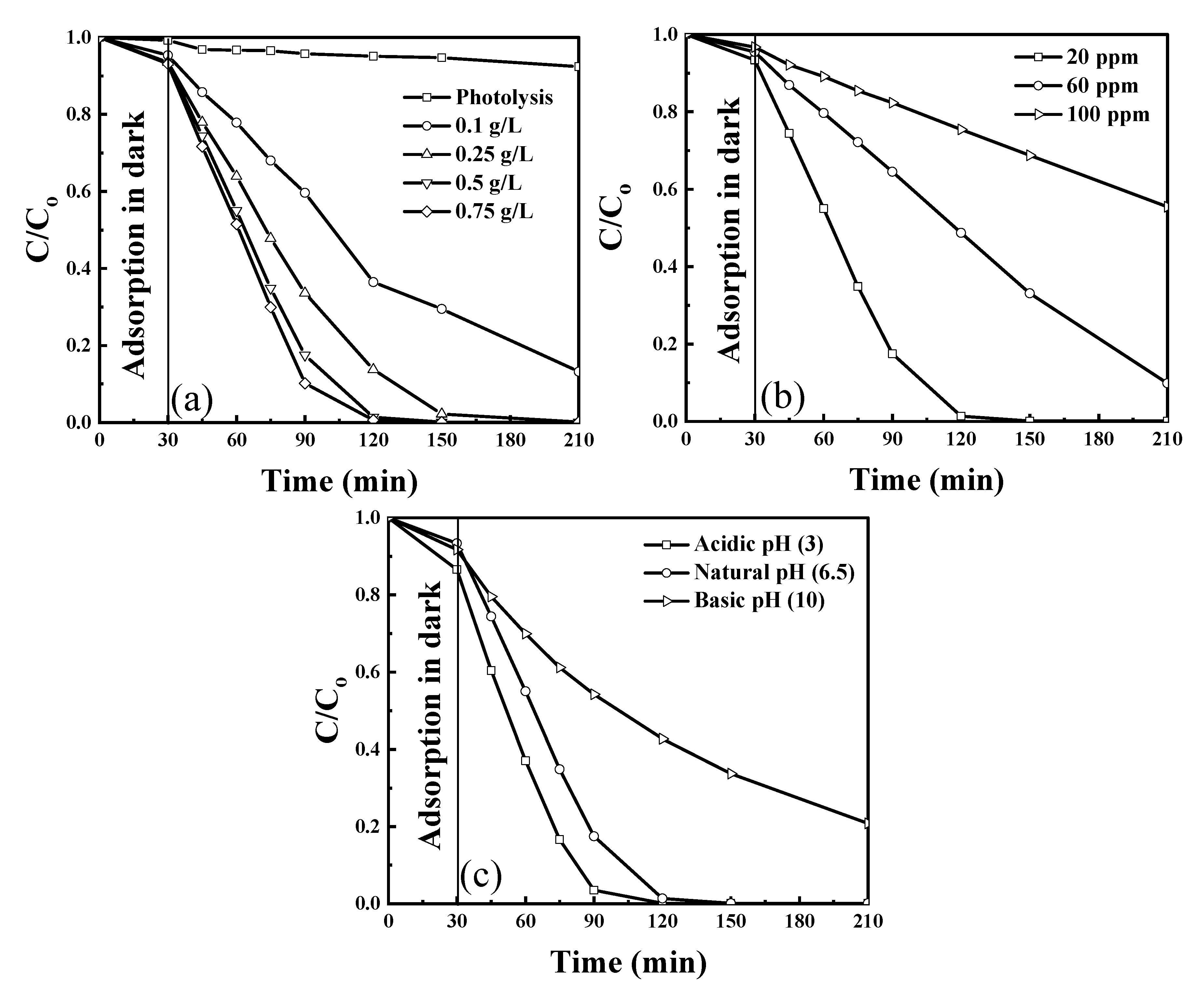
3.2. Photodegradation Studies

The photodegradation efficiency of exfoliated g-C3N4 photocatalyst was evaluated under visible light irradiation using 430 nm wavelength LEDs. The influence of individual operation parameters, catalyst concentration, phenol concentration, and pH of the solution, in their preselected ranges (Table 1), was examined. For all experiments, an adsorption time of 30 min was used before the light irradiation was started. Moreover, the photolysis experiment was performed to verify the removal of phenol in the absence of the catalyst. Phenol removal with adsorption in the dark and photolysis is insignificant compared to the removal of phenol obtained in the presence of light (Figure 5a). Figure 5a shows the effect of g-C3N4 photocatalyst concentration in the range of 0.1–0.75 g/L on phenol degradation, which increased with the increase in catalyst concentration up to 0.75 g/L because of an increased number of active sites available for the reaction to occur. However, there is no significant increase at >0.5 g/L because an additional increase of the catalyst concentration might cause light scattering and hindrance in light absorption. The effect of phenol concentration on the performance of the catalyst on phenol degradation was examined for three concentrations between 20 and 100 ppm and is shown in Figure 5b. The phenol degradation efficiency decreased as the concentration increased because of the higher number of molecules for adsorption on the available active sites, which hinders the absorption of light. Figure 5c shows the effect of different pH on phenol degradation. Increasing the pH decreases the degradation efficiency of exfoliated g-C3N4. Note that acidic pH is most favorable for phenol degradation because as per the zeta potential (Figure 3) and the surface charge of the catalyst is positive at an acidic pH, which helps attract OH– ions produced in the solution due to dissociation of H2O2 to the surface and improves the degradation efficiency.

3.3. Response Surface Methodology

3.3.1. Model Equation

To analyze the combined effect of three variables: catalyst concentration (A), phenol concentration (B), and pH of the solution (C) on the degradation efficiency of phenol (Equation (1)), a three-variable BBD was used in the experimental design for RSM. Table 3 lists the set of performed experiments and the obtained phenol degradation (in 3 h and under an airflow of 50 mL/min).
Experimental data were fitted with four different models: two-factor interaction (2FI), linear, quadratic, and cubic model to obtain regression equations. Three different tests, namely, the sequential model sum of squares, lack of fit, and model summary statistics, were conducted to determine the adequacy of various models; the results are presented in Table 4. The response surface model is then used to select the best model based on the following criterion: the highest-order polynomial with additional significant terms and the model is not aliased (Table 4). The cubic model has the highest polynomial model because there are no sufficient unique design points to independently estimate all terms for that model. The aliased model results in unstable and inaccurate coefficients and graphs. Thus, the aliased model cannot be selected [49,50]. The criteria used in the lack of fit test is the non-significant lack of fit (p-value > 0.05) based on which a quadratic model is selected. Moreover, multiple summary statistics are calculated to compare models or to confirm the adequacy of the model. These statistics include adjusted R2, predicted R2, and prediction error sum of squares (PRESS). A good model will have a largely predicted r2, and a low PRESS. According to the aforementioned criteria, adjusted R2 (0.967) and predicted R2 (0.805) are in reasonable agreement with each other and have a low PRESS. Thus, the quadratic model is finally selected to build the response surface.
Based on regression coefficients from Table 5, the following empirical second-order polynomial equation was obtained:
Degradation   Efficiency   ( % ) = 85.72 + 6.36   A 24.86   B 15.22   C + 3.71   AB 2.83   AC 2.38   BC 5.05   A 2 5.22   B 2 16.07   C 2
where, A, B, and C are the catalyst concentration, phenol concentration, and pH of the solution, respectively.
The influence of model terms on the degradation of phenol as per p-values (Table 5) is in the following order B < C < C2 < A < B2 < A2 < AB < AC < BC. The mixed interaction terms AB, AC, and BC are not significant because their p–value is > 0.05 and may be removed from Equation (2).
An ANOVA of the second-order polynomial (Equation (2)) for phenol degradation was conducted; the results are shown in Table 6. In statistics, the significance of the model can be confirmed by a large F-value (53.31) and a small p-value (<0.0001). Furthermore, the significance of the model can be confirmed by the lack of fit test. In this study, the lack of fit is not significant because its p-value is >0.05. The accuracy of the model is confirmed by the low coefficient of variation (CV) value of 5.79%. The results showed that the signal-to-noise ratio of 24.89 is adequate.
Furthermore, the coefficient of determination R2 confirmed the fit of the model. For the used model, the value of the predicted R2 = 0.810 (Table 6) is in agreement with adjusted R2 = 0.967, which indicates that the obtained model is significant.
Equation (2) provides a suitable relationship (R2 = 0.810) between the response (degradation efficiency) and the parameters, which can be seen in Figure 6. In this figure, the experimental values of phenol degradation are plotted against the predicted values obtained from the RSM model; these values of the percentage phenol degradation fit well.

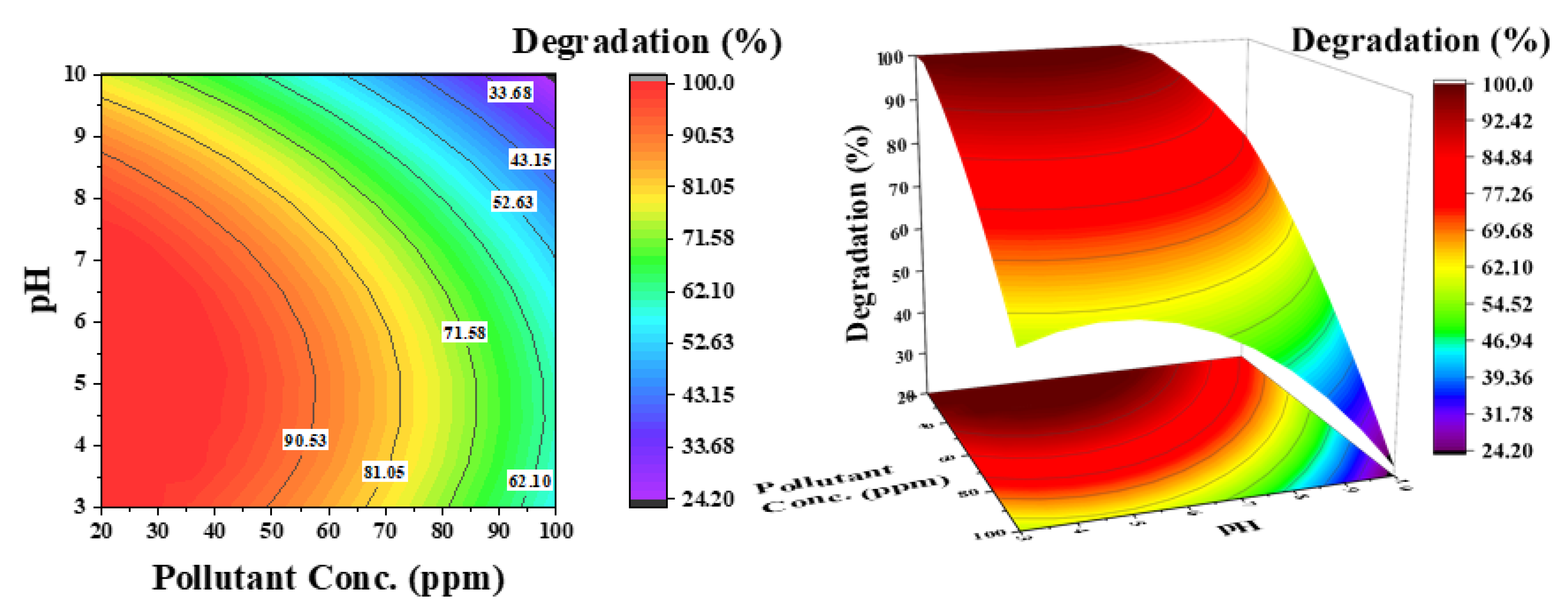
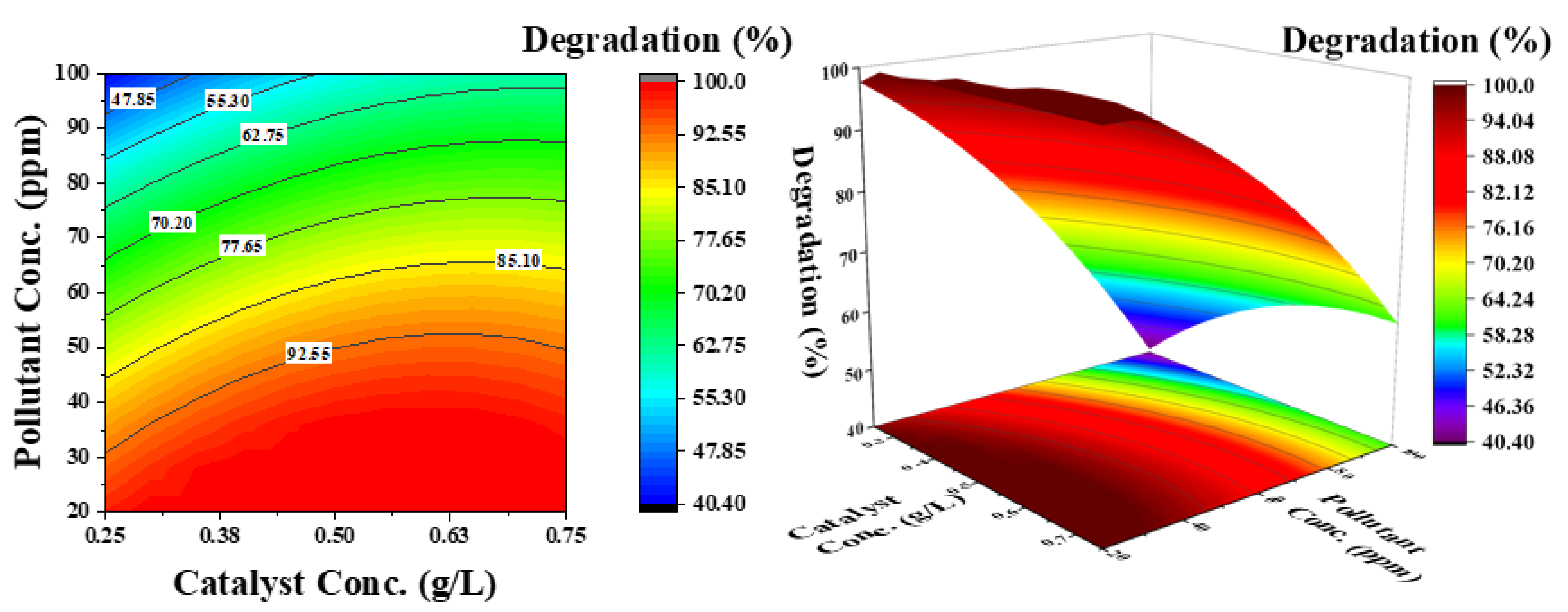
3.3.2. Interaction Effects of Independent Operating Parameters

Three dimensional (3D) response surface and contour plots were generated using the regression model (Equation (2)) to visualize the influence of the independent operating parameters on phenol degradation; they are presented in Figure 7, Figure 8 and Figure 9. In surface and contour plots, one parameter is maintained constant at its zero levels, whereas the other two are varied in the studied range reported in Table 1.
Figure 7 shows the influence of pH and catalyst concentration on the degradation efficiency of phenol at a constant phenol concentration of 60 ppm. The contour lines show a decrease in the degradation efficiency with an increase in pH; there is no considerable increase in efficiency, even at higher catalyst concentrations. However, an increase in degradation efficiency with a decrease in pH is observed. These results demonstrate that pH has a significant effect on phenol degradation and a low pH favors the degradation process. This phenomenon is linked with the zeta potential of the catalyst surface [18]. There is a positive charge at the surface of the catalyst at an acidic pH (Figure 2), which attracts the OH ions produced in the solution due to dissociation of H2O2 and significantly increases the degradation process. However, at a basic pH, the surface charge is negative and there could be electrostatic repulsion that reduces the efficiency of the degradation process.
Figure 8 shows the influence of pH and pollutant concentration on phenol degradation at a constant catalyst concentration of 0.5 g/L. For selecting the catalyst concentration, the effect of initial pollutant concentration is important. The contour lines demonstrate that simultaneously increasing both parameters (pH and phenol concentration) considerably decreases the degradation efficiency of phenol (33%), which is 62% at a low pH. As shown in Figure 5b, at low pH and low pollutant concentration, 100% degradation is achieved in a considered reaction time of 3 h. An increase in degradation efficiency from high to low pH can then be associated with catalyst surface charge. However, a decrease in efficiency at low pH from low to high phenol concentration is attributed to the increased number of pollutant molecules compared with the available active sites.
Figure 9 shows the effect of catalyst concentration and pollutant concentration at a constant pH of 6.5. The contour lines demonstrate that both parameters independently affect the degradation efficiency. By increasing the catalyst concentration at a lower pollutant concentration, phenol degradation increases; however, at a higher pollutant concentration, the degradation efficiency decreases. This can be attributed to the availability of active sites on the catalyst surface for OH radicals, as well as phenol molecules. The electron–hole pair generated from the catalyst surface improves the degradation rate.

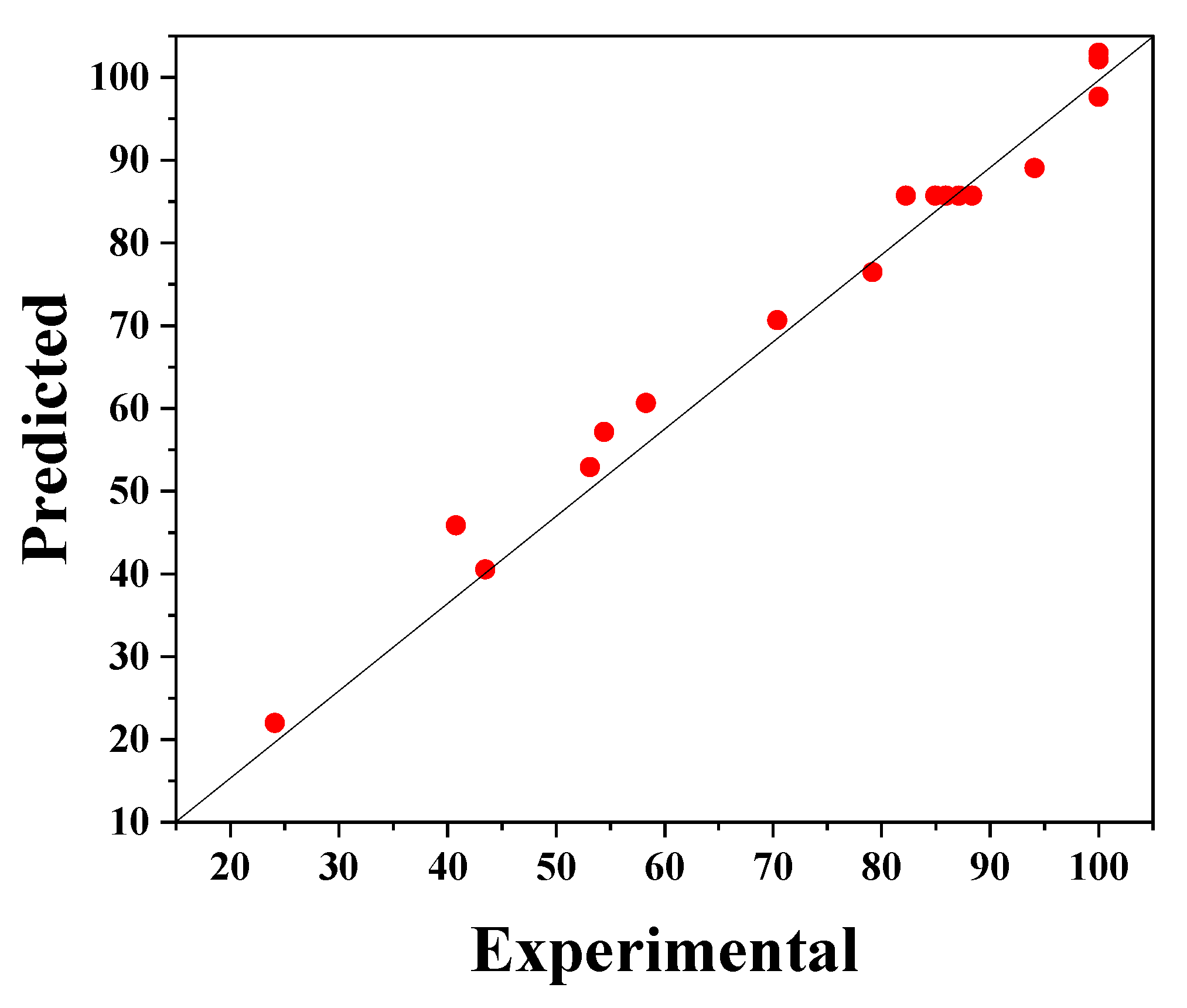
3.3.3. Experimental Validation of RSM Model

To demonstrate the applicability of the model, a hypothetical case study for water with a phenol concentration of 50 ppm was considered. The model equation was used to identify the optimum catalyst concentration and pH, leading to maximal phenol degradation in 3 h under an airflow rate of 50 mL/min. According to the model prediction, maximal phenol degradation of 88.62% is achievable using 0.4 g/L of catalyst concentration and operating at a pH of 6.5. To examine the accuracy of the model prediction, an experiment was conducted under these conditions. The experimentally obtained phenol degradation was 83.75%, which is less than a 5% deviation from the predicted value. Thus, the optimum operating point obtained by RSM was successfully confirmed; this suggests that RSM can be a useful tool for optimizing photocatalytic processes. Similarly, the model developed can be used for minimizing the catalyst amount or for maximizing the degradation efficiency of phenols for any set of parameters in range.

4. Conclusions

Metal-free g-C3N4 was used for the photocatalytic degradation of phenol from an aqueous solution. The morphology of the catalyst was confirmed by SEM, and the surface charge was confirmed using zeta potential. Based on zeta potential, the catalyst surface was confirmed to have a positive surface charge under acidic conditions and a negative surface charge under basic conditions; therefore, acidic pH favors the degradation process. A RSM based on the BBD was used to analyze the degradation efficiency of phenol. The influence of experimental parameters, namely, catalyst concentration, pollutant concentration, and pH of the solution, and their interaction at a different level was examined for phenol degradation. An empirical regression quadratic model was developed for the response variable. Analysis of variance (ANOVA) demonstrated that the model is significant with an insignificant lack of fit and a high coefficient of determination (R2) of 0.96, which can be helpful to navigate the design space. Furthermore, an optimized degradation efficiency of 83.75% was achieved for phenol concentration of 50 ppm, catalyst concentration of 0.4 g/L, and a solution pH of 6.5 pH (in 3 h and under an airflow of 50 mL/min). Thus, the results suggest that the RSM can be used for the optimization of parameters for maximizing the photocatalytic degradation of phenol using g-C3N4 and LEDs.

Supplementary Materials

The following are available online at https://0-www-mdpi-com.brum.beds.ac.uk/article/10.3390/catal11080898/s1, Figure S1 N2 adsorption-desorption isotherms of bulk and exfoliated g-C3N4. The inset shows the corresponding BJH pore size distribution curves of the sample, Figure S2 (a) UV-Vis absorption spectra and (b) PL spectra of bulk and exfoliated g-C3N4; insets of (a) showing the Tauc plots, Figure S3 XPS spectra of bulk and exfoliated g-C3N4 C1s, N1s, Figure S4 X-ray diffraction patterns of bulk and exfoliated g-C3N4.

Author Contributions

Conceptualization, A.G.R.; Formal analysis, A.G.R.; Investigation, A.G.R.; Methodology, A.G.R.; Resources, M.M.; Supervision, M.M.; Writing—original draft, A.G.R.; Writing—review and editing, M.M. All authors have read and agreed to the published version of the manuscript.

Funding

This research received no external funding.

Acknowledgments

A.G.R. acknowledges the financial support from the Higher Education Commission, Pakistan, and Deutscher Akademischer Austauschdienst (DAAD), Germany.

Conflicts of Interest

The authors declare no conflict of interest.

References

  1. Zulfiqar, M.; Samsudin, M.F.R.; Sufian, S. Modelling and optimization of photocatalytic degradation of phenol via TiO2 nanoparticles: An insight into response surface methodology and artificial neural network. J. Photochem. Photobiol. A Chem. 2019, 384, 112039. [Google Scholar] [CrossRef]
  2. Jourshabani, M.; Shariatinia, Z.; Badiei, A. Facile one-pot synthesis of cerium oxide/sulfur-doped graphitic carbon nitride (g-C3N4) as efficient nanophotocatalysts under visible light irradiation. J. Colloid Interface Sci. 2017, 507, 59–73. [Google Scholar] [CrossRef] [PubMed]
  3. Hassani, A.; Eghbali, P.; Metin, O. Sonocatalytic removal of methylene blue from water solution by cobalt ferrite/mesoporous graphitic carbon nitride (CoFe2O4/mpg-C3N4) nanocomposites: Response surface methodology approach. Environ. Sci. Pollut. Res. Int. 2018, 25, 32140–32155. [Google Scholar] [CrossRef] [PubMed]
  4. Mirzaei, A.; Yerushalmi, L.; Chen, Z.; Haghighat, F. Photocatalytic degradation of sulfamethoxazole by hierarchical magnetic ZnO@g-C3N4: RSM optimization, kinetic study, reaction pathway and toxicity evaluation. J. Hazard. Mater. 2018, 359, 516–526. [Google Scholar] [CrossRef]
  5. Choquette-Labbé, M.; Shewa, W.; Lalman, J.; Shanmugam, S. Photocatalytic Degradation of Phenol and Phenol Derivatives Using a Nano-TiO2 Catalyst: Integrating Quantitative and Qualitative Factors Using Response Surface Methodology. Water 2014, 6, 1785–1806. [Google Scholar] [CrossRef] [Green Version]
  6. Yasar Arafath, K.A.; Baskaralingam, P.; Gopinath, S.; Nilavunesan, D.; Sivanesan, S. Degradation of phenol from retting-pond wastewater using anaerobic sludge reactor integrated with photo catalytic treatment. Chem. Phys. Lett. 2019, 734, 136727. [Google Scholar] [CrossRef]
  7. Hararah, M.A.; Ibrahim, K.A.; Al-Muhtaseb, A.a.H.; Yousef, R.I.; Abu-Surrah, A.; Qatatsheh, A.a. Removal of phenol from aqueous solutions by adsorption onto polymeric adsorbents. J. Appl. Polym. Sci. 2010, 117, 1908–1913. [Google Scholar] [CrossRef]
  8. Aslam, Z.; Qaiser, M.; Ali, R.; Abbas, A.; Ihsanullah; Zarin, S. Al2O3/MnO2/CNTs nanocomposite: Synthesis, characterization and phenol adsorption. Fuller. Nanotub. Carbon Nanostruct. 2019, 27, 591–600. [Google Scholar] [CrossRef]
  9. Huang, C.H.; Liou, R.M.; Chen, S.H.; Hung, M.Y.; Lai, C.L.; Lai, J.Y. Microbial degradation of phenol in a modified three-stage airlift packing-bed reactor. Water Environ. Res. 2010, 82, 249–258. [Google Scholar] [CrossRef]
  10. Yavuz, Y.; Savas Koparal, A.; Bakir Ögütveren, Ü. Phenol Removal through Chemical Oxidation using Fenton Reagent. Chem. Eng. Technol. 2007, 30, 583–586. [Google Scholar] [CrossRef]
  11. Asanjarani, N.; Bagtash, M.; Zolgharnein, J. A comparison between Box–Behnken design and artificial neural network: Modeling of removal of Phenol Red from water solutions by nanocobalt hydroxide. J. Chemom. 2020, 34, e3283. [Google Scholar] [CrossRef]
  12. Peng, H.; Zou, C.; Wang, C.; Tang, W.; Zhou, J. The effective removal of phenol from aqueous solution via adsorption on CS/beta-CD/CTA multicomponent adsorbent and its application for COD degradation of drilling wastewater. Environ. Sci. Pollut. Res. Int. 2020, 27, 33668–33680. [Google Scholar] [CrossRef] [PubMed]
  13. Chowdhury, P.; Nag, S.; Ray, A.K. Degradation of Phenolic Compounds through UV and Visible-Light-Driven Photocatalysis: Technical and Economic Aspects. In Phenolic Compounds—Natural Sources, Importance and Applications; IntechOpen: London, UK, 2017. [Google Scholar] [CrossRef] [Green Version]
  14. Tetteh, E.K.; Rathilal, S.; Naidoo, D.B. Photocatalytic degradation of oily waste and phenol from a local South Africa oil refinery wastewater using response methodology. Sci. Rep. 2020, 10, 8850. [Google Scholar] [CrossRef] [PubMed]
  15. Md Rosli, N.I.; Lam, S.-M.; Sin, J.-C.; Satoshi, I.; Mohamed, A.R. Photocatalytic Performance of ZnO/g-C3N4 for Removal of Phenol under Simulated Sunlight Irradiation. J. Environ. Eng. 2018, 144, 04017091. [Google Scholar] [CrossRef]
  16. Rana, A.G.; Ahmad, W.; Al-Matar, A.; Shawabkeh, R.; Aslam, Z. Synthesis and characterization of Cu-Zn/TiO2 for the photocatalytic conversion of CO2 to methane. Environ. Technol. 2017, 38, 1085–1092. [Google Scholar] [CrossRef]
  17. Lima, M.J.; Silva, A.M.T.; Silva, C.G.; Faria, J.L. Graphitic carbon nitride modified by thermal, chemical and mechanical processes as metal-free photocatalyst for the selective synthesis of benzaldehyde from benzyl alcohol. J. Catal. 2017, 353, 44–53. [Google Scholar] [CrossRef]
  18. Rana, A.G.; Tasbihi, M.; Schwarze, M.; Minceva, M. Efficient Advanced Oxidation Process (AOP) for Photocatalytic Contaminant Degradation Using Exfoliated Metal-Free Graphitic Carbon Nitride and Visible Light-Emitting Diodes. Catalysts 2021, 11, 662. [Google Scholar] [CrossRef]
  19. Al-Kandari, H.; Abdullah, A.M.; Ahmad, Y.H.; Al-Kandari, S.; AlQaradawi, S.Y.; Mohamed, A.M. An efficient eco advanced oxidation process for phenol mineralization using a 2D/3D nanocomposite photocatalyst and visible light irradiations. Sci. Rep. 2017, 7, 9898. [Google Scholar] [CrossRef] [PubMed] [Green Version]
  20. Moradi, V.; Ahmed, F.; Jun, M.B.G.; Blackburn, A.; Herring, R.A. Acid-treated Fe-doped TiO2 as a high performance photocatalyst used for degradation of phenol under visible light irradiation. J. Environ. Sci. 2019, 83, 183–194. [Google Scholar] [CrossRef] [PubMed]
  21. Nobijari, L.A.; Schwarze, M.; Tasbihi, M. Photocatalytic Degradation of Phenol Using Photodeposited Pt Nanoparticles on Titania. J. Nanosci. Nanotechnol. 2020, 20, 1056–1065. [Google Scholar] [CrossRef] [PubMed]
  22. Jourshabani, M.; Shariatinia, Z.; Badiei, A. In situ fabrication of SnO2/S-doped g-C3N4 nanocomposites and improved visible light driven photodegradation of methylene blue. J. Mol. Liq. 2017, 248, 688–702. [Google Scholar] [CrossRef]
  23. Jourshabani, M.; Shariatinia, Z.; Badiei, A. Sulfur-Doped Mesoporous Carbon Nitride Decorated with Cu Particles for Efficient Photocatalytic Degradation under Visible-Light Irradiation. J. Phys. Chem. C 2017, 121, 19239–19253. [Google Scholar] [CrossRef]
  24. Jourshabani, M.; Shariatinia, Z.; Badiei, A. Controllable Synthesis of Mesoporous Sulfur-Doped Carbon Nitride Materials for Enhanced Visible Light Photocatalytic Degradation. Langmuir 2017, 33, 7062–7078. [Google Scholar] [CrossRef]
  25. Lee, S.C.; Lintang, H.O.; Yuliati, L. A urea precursor to synthesize carbon nitride with mesoporosity for enhanced activity in the photocatalytic removal of phenol. Chem. Asian J. 2012, 7, 2139–2144. [Google Scholar] [CrossRef] [PubMed]
  26. Ren, H.-T.; Jia, S.-Y.; Wu, Y.; Wu, S.-H.; Zhang, T.-H.; Han, X. Improved Photochemical Reactivities of Ag2O/g-C3N4 in Phenol Degradation under UV and Visible Light. Ind. Eng. Chem. Res. 2014, 53, 17645–17653. [Google Scholar] [CrossRef]
  27. Deng, P.; Gan, M.; Zhang, X.; Li, Z.; Hou, Y. Non-noble-metal Ni nanoparticles modified N-doped g-C3N4 for efficient photocatalytic hydrogen evolution. Int. J. Hydrogen Energy 2019, 44, 30084–30092. [Google Scholar] [CrossRef]
  28. Hu, J.Y.; Tian, K.; Jiang, H. Improvement of phenol photodegradation efficiency by a combined g-C3N4/Fe(III)/persulfate system. Chemosphere 2016, 148, 34–40. [Google Scholar] [CrossRef] [PubMed]
  29. Huang, Z.; Li, F.; Chen, B.; Lu, T.; Yuan, Y.; Yuan, G. Well-dispersed g-C3N4 nanophases in mesoporous silica channels and their catalytic activity for carbon dioxide activation and conversion. Appl. Catal. B Environ. 2013, 136–137, 269–277. [Google Scholar] [CrossRef]
  30. Sharma, M.; Vaidya, S.; Ganguli, A.K. Enhanced photocatalytic activity of g-C3N4-TiO2 nanocomposites for degradation of Rhodamine B dye. J. Photochem. Photobiol. A Chem. 2017, 335, 287–293. [Google Scholar] [CrossRef]
  31. Hernández-Uresti, D.B.; Vázquez, A.; Sanchez-Martinez, D.; Obregón, S. Performance of the polymeric g-C3N4 photocatalyst through the degradation of pharmaceutical pollutants under UV–vis irradiation. J. Photochem. Photobiol. A Chem. 2016, 324, 47–52. [Google Scholar] [CrossRef]
  32. Abdullah, A.H.; Moey, H.J.M.; Yusof, N.A. Response surface methodology analysis of the photocatalytic removal of Methylene Blue using bismuth vanadate prepared via polyol route. J. Environ. Sci. 2012, 24, 1694–1701. [Google Scholar] [CrossRef]
  33. Song, C.; Li, X.; Wang, L.; Shi, W. Fabrication, Characterization and Response Surface Method (RSM) Optimization for Tetracycline Photodegration by Bi3.84W0.16O6.24-graphene oxide (BWO-GO). Sci. Rep. 2016, 6, 37466. [Google Scholar] [CrossRef] [Green Version]
  34. Wang, J.; Guo, P.; Dou, M.; Wang, J.; Cheng, Y.; Jönsson, P.G.; Zhao, Z. Visible light-driven g-C3N4/m-Ag2Mo2O7composite photocatalysts: Synthesis, enhanced activity and photocatalytic mechanism. RSC Adv. 2014, 4, 51008–51015. [Google Scholar] [CrossRef]
  35. Wang, Y.; Yang, W.; Chen, X.; Wang, J.; Zhu, Y. Photocatalytic activity enhancement of core-shell structure g-C3N4@TiO2 via controlled ultrathin g-C3N4 layer. Appl. Catal. B Environ. 2018, 220, 337–347. [Google Scholar] [CrossRef]
  36. Yuan, Y.-J.; Shen, Z.; Wu, S.; Su, Y.; Pei, L.; Ji, Z.; Ding, M.; Bai, W.; Chen, Y.; Yu, Z.-T.; et al. Liquid exfoliation of g-C3N4 nanosheets to construct 2D-2D MoS2/g-C3N4 photocatalyst for enhanced photocatalytic H2 production activity. Appl. Catal. B Environ. 2019, 246, 120–128. [Google Scholar] [CrossRef]
  37. Muñoz-Batista, M.J.; Rodríguez-Padrón, D.; Puente-Santiago, A.R.; Kubacka, A.; Luque, R.; Fernández-García, M. Sunlight-Driven Hydrogen Production Using an Annular Flow Photoreactor and g-C3N4-Based Catalysts. ChemPhotoChem 2018, 2, 870–877. [Google Scholar] [CrossRef]
  38. Yuan, X.; Zhou, C.; Jin, Y.; Jing, Q.; Yang, Y.; Shen, X.; Tang, Q.; Mu, Y.; Du, A.K. Facile synthesis of 3D porous thermally exfoliated g-C3N4 nanosheet with enhanced photocatalytic degradation of organic dye. J. Colloid Interface Sci. 2016, 468, 211–219. [Google Scholar] [CrossRef] [Green Version]
  39. Xu, J.; Zhang, L.; Shi, R.; Zhu, Y. Chemical exfoliation of graphitic carbon nitride for efficient heterogeneous photocatalysis. J. Mater. Chem. A 2013, 1, 14766–14772. [Google Scholar] [CrossRef]
  40. Li, Y.; Wang, M.-Q.; Bao, S.-J.; Lu, S.; Xu, M.; Long, D.; Pu, S. Tuning and thermal exfoliation graphene-like carbon nitride nanosheets for superior photocatalytic activity. Ceram. Int. 2016, 42, 18521–18528. [Google Scholar] [CrossRef]
  41. Yang, L.; Liu, X.; Liu, Z.; Wang, C.; Liu, G.; Li, Q.; Feng, X. Enhanced photocatalytic activity of g-C3N4 2D nanosheets through thermal exfoliation using dicyandiamide as precursor. Ceram. Int. 2018, 44, 20613–20619. [Google Scholar] [CrossRef]
  42. Papailias, I.; Giannakopoulou, T.; Todorova, N.; Demotikali, D.; Vaimakis, T.; Trapalis, C. Effect of processing temperature on structure and photocatalytic properties of g-C3N4. Appl. Surf. Sci. 2015, 358, 278–286. [Google Scholar] [CrossRef]
  43. Yu, B.; Meng, F.; Khan, M.W.; Qin, R.; Liu, X. Facile synthesis of AgNPs modified TiO2@g-C3N4 heterojunction composites with enhanced photocatalytic activity under simulated sunlight. Mater. Res. Bull. 2020, 121, 110641. [Google Scholar] [CrossRef]
  44. Yang, Y.; Lei, W.; Xu, Y.; Zhou, T.; Xia, M.; Hao, Q. Determination of trace uric acid in serum using porous graphitic carbon nitride (g-C3N4) as a fluorescent probe. Microchim. Acta 2017, 185, 39. [Google Scholar] [CrossRef] [PubMed]
  45. Dong, F.; Wang, Z.; Sun, Y.; Ho, W.K.; Zhang, H. Engineering the nanoarchitecture and texture of polymeric carbon nitride semiconductor for enhanced visible light photocatalytic activity. J. Colloid Interface Sci. 2013, 401, 70–79. [Google Scholar] [CrossRef] [PubMed]
  46. Sturini, M.; Speltini, A.; Maraschi, F.; Vinci, G.; Profumo, A.; Pretali, L.; Albini, A.; Malavasi, L. g-C3N4-promoted degradation of ofloxacin antibiotic in natural waters under simulated sunlight. Environ. Sci. Pollut. Res. Int. 2017, 24, 4153–4161. [Google Scholar] [CrossRef] [PubMed]
  47. Zhu, B.; Xia, P.; Ho, W.; Yu, J. Isoelectric point and adsorption activity of porous g-C3N4. Appl. Surf. Sci. 2015, 344, 188–195. [Google Scholar] [CrossRef]
  48. Praus, P.; Svoboda, L.; Dvorský, R.; Reli, M. Nanocomposites of SnO2 and g-C3N4: Preparation, characterization and photocatalysis under visible LED irradiation. Ceram. Int. 2018, 44, 3837–3846. [Google Scholar] [CrossRef]
  49. Kumar, M.; Ponselvan, F.I.; Malviya, J.R.; Srivastava, V.C.; Mall, I.D. Treatment of bio-digester effluent by electrocoagulation using iron electrodes. J. Hazard. Mater. 2009, 165, 345–352. [Google Scholar] [CrossRef] [PubMed]
  50. Liu, J.; Wang, J.; Leung, C.; Gao, F. A Multi-Parameter Optimization Model for the Evaluation of Shale Gas Recovery Enhancement. Energies 2018, 11, 654. [Google Scholar] [CrossRef] [Green Version]
Figure 1. Photocatalytic reactor setup.
Catalysts 11 00898 g001
Figure 2. SEM images of the bulk (a) and exfoliated (b) g-C3N4.
Catalysts 11 00898 g002
Figure 3. Fourier transform infrared spectra of bulk and exfoliated g-C3N4.
Catalysts 11 00898 g003
Figure 4. Zeta potential at different pH of the synthesized exfoliated g-C3N4. Reproduced with permission from [18].
Catalysts 11 00898 g004
Figure 5. Phenol degradation at preselected (a) catalyst concentration (at 20 ppm and natural pH) (b) pollutant concentration (at 0.5 g/L and natural pH), and (c) pH of the solution (at 0.5 g/L and 20 ppm); airflow = 50 mL/min. Reproduced with permission from [18].
Catalysts 11 00898 g005
Figure 6. The experimental phenol degradation efficiency (%) plotted against the predicted values from the RSM model.
Catalysts 11 00898 g006
Figure 7. Effect of catalyst concentration and pH on the degradation of phenol: pollutant concentration was kept constant at 60 ppm.
Catalysts 11 00898 g007
Figure 8. Effect of pollutant concentration and pH on the degradation of phenol: catalyst concentration was kept constant at 0.5 g/L.
Catalysts 11 00898 g008
Figure 9. Effect of catalyst concentration and pollutant concentration on the degradation of phenol: pH was kept constant at 6.5.
Catalysts 11 00898 g009
Table 1. Independent parameters and their ranges and levels.
Independent ParametersSymbolRange and Level
Low (−1)Middle (0)High (+1)
Catalyst concentration (g/L)A0.250.50.75
Phenol initial concentration (ppm)B2060100
pHC36.510
Table 2. Summary of characterization results [18].
CharacterizationBulk g-C3N4Exfoliated g-C3N4
BETSurface areaPore sizeSurface areaPore size
11 m2/g1.91 Å170 m2/g1.96 Å
XRDWeak peaks (2θ)Strong peaks (2θ)Weak peaks (2θ)Strong peaks (2θ)
13.0°27.2°13.1°27.4°
PL/UV-VisMax. absorptionBandgapMax. absorptionBandgap
458 nm2.58 eV436 nm2.68 eV
XPSC1s peaksN1s peaksC1s peaksN1s peaks
288.2, 284.6, 286.2 and 292.9 eV398.5, 399.8, 400.8, 404.1 eV287.8, 284.7, 286.2 and 293.5 eV397.8, 399.1, 400.1, 403.5 eV
Table 3. Box–Behnken design with experimental and predicted phenol degradation efficiency values with Equation (2).
RunExperimental ConditionsPhenol Degradation Efficiency (%)
Catalyst Concentration (g/L)Phenol Initial Concentration (ppm)pHExperimentalPredicted
10.251006.543.4944.23
20.50606.582.2585.72
30.25206.510093.95
40.75603.094.0986.18
50.75206.5100.00100.00
60.502010.079.1874.07
70.50203.0100.00100.00
80.50606.584.9385.72
90.256010.040.7743.02
100.50606.585.9485.72
110.5010010.024.0924.35
120.501003.054.4354.79
130.756010.053.1555.74
140.25603.070.3973.46
150.50606.588.3785.72
160.751006.558.3156.95
170.50606.587.1285.72
Table 4. Adequacy of the models tested.
SourceSum of SquaresDegree of FreedomMean SquareF Valuep-ValueRemark
Sequential model sum of squares
Linear7118.9832372.9918.77<0.0001-
2FI109.60336.530.2380.8678-
Quadratic1407.833469.2726.070.0004Suggested
Cubic104.30334.766.410.0523Aliased
Lack of fit tests
Linear1621.739180.1933.22<0.0021-
2FI1512.136252.0246.46<0.0012-
Quadratic104.29334.766.410.0523Suggested
Cubic00---Aliased
SourceStandard deviationR2Adjusted R2Predicted R2PRESS-
Model summary statistic
Linear11.240.81240.7690.6942678.06-
2FI12.380.82500.7200.4624712.53-
Quadratic4.240.98560.9670.8051702.70Suggested
Cubic2.330.99750.999--Aliased
Table 5. Coefficients of the second-order polynomial (quadratic) equation.
FactorCoefficient EstimateDegree of FreedomStandard Error95% Confidence Interval Low95% Confidence Interval LowF Valuep-Value
Intercept85.7211.9081.2490.21--
A6.3611.502.829.9117.990.0038
B−24.8611.50−28.40−21.31274.63<0.0001
C−15.2211.50−18.76−11.67102.89<0.0001
AB3.7112.12−1.318.723.050.1242
AC−2.8312.12−7.852.191.780.2239
BC−2.3812.12−7.402.641.260.2989
A2−5.0512.07−9.94−0.165.960.0446
B2−5.2212.07−10.11−0.336.380.0394
C2−16.0712.07−20.96−11.1860.440.0001
Table 6. Analysis of variance ANOVA of the second-order polynomial (Equation (2)).
SourceSum of SquaresDegree of FreedomMean SquareF Valuep-ValueRemark
Model8636.429959.6053.31<0.0001Significant
Residual126.00718.00---
Lack of fit104.30334.776.410.0523Not Significant
Pure error21.7045.42---
-Adjusted R2 = 0.967Predicted R2 = 0.810Model precision = 24.89--
-Std. dev. = 4.24Mean = 73.32C.V. % = 5.79 ---
Publisher’s Note: MDPI stays neutral with regard to jurisdictional claims in published maps and institutional affiliations.

