Article

Stability of a NiAl2O4 Derived Catalyst in the Ethanol Steam Reforming in Reaction-Regeneration Cycles: Effect of Reduction Temperature

by
Sergio Iglesias-Vázquez
,
José Valecillos
*,
Aingeru Remiro
,
Javier Bilbao
and
Ana Guadalupe Gayubo
Department of Chemical Engineering, University of the Basque Country (UPV/EHU), P.O. Box 644, 48080 Bilbao, Spain
*
Author to whom correspondence should be addressed.
Submission received: 26 April 2022 / Revised: 10 May 2022 / Accepted: 16 May 2022 / Published: 17 May 2022
(This article belongs to the Section Catalysis for Sustainable Energy)

Abstract

:
The catalyst regeneration is still a challenge to make the ethanol steam reforming (ESR) process feasible for sustainable H2 production. NiAl2O4 spinel derived catalysts are highly active and selective for ESR, but they require avoiding irreversible deactivation to ensure their regeneration. Their stability depends on the catalyst structure, and herein we report different Ni/Al2O3-NiAl2O4 catalysts obtained upon reduction of a NiAl2O4 spinel at 700, 750, or 850 °C. The catalysts were tested in ESR reaction-regeneration cycles, with reaction at 600 °C and regeneration by coke combustion at 850 °C followed by reduction at the corresponding temperature. The fresh, spent, and regenerated catalysts were characterized using X-ray diffraction, N2 physisorption, temperature programmed reduction and oxidation, and scanning electron microscopy. The irreversible deactivation is due to Ni volatilization and catalyst particle fragmentation. These phenomena are prompted by a high filamentous carbon deposition favored by the Al2O3 content in the catalyst. The reduction in the 700–750 °C range is optimum for controlling the Al2O3 content, increasing the NiAl2O4/Al2O3 ratio in the resulting catalyst. These catalysts show a period of partial reversible deactivation by coke with a change in the H2 formation mechanism reaching a pseudo-stable state with a H2 yield of 40% and a reproducible performance in successive reaction-regeneration cycles.

1. Introduction

Hydrogen is a promising energy vector [1] and raw material for the synthesis of commodities [2], complying with sustainability precepts when it is obtained from renewable raw materials. H2 production from ethanol via steam reforming (ESR) is a suitable alternative since ethanol can be obtained sustainably from biomass (bio-ethanol) by fermentation/hydrolysis with no need to separate the water and is easy to handle with relative low risks in comparison with other feedstock for the H2 production [3,4]. Moreover, the ESR fundamentals are similar to those of CH4 steam reforming (MSR) which is the basis of the largest technology for H2 production from natural gas extended worldwide [5], representing an advantage for making an easier adaptation and transition to sustainable H2 production from ethanol.
The ESR process involves several reactions in a complex series-parallel scheme, in which ethanol reforming (Equation (1)) and water gas shift (Equation (2)) are the main reactions giving the global steam reforming reaction represented by Equation (3) [3,6,7,8]. However, ethanol may undergo dehydrogenation (Equation (4)), dehydration (Equation (5)), and decomposition (Equation (6)) yielding up more H2 or intermediates (ethylene and acetaldehyde). Acetaldehyde and ethylene may undergo steam reforming (Equations (7) and (8), respectively) and decomposition (Equations (9) and (10), respectively). CH4 may be formed from some decomposition reactions (Equations (6) and (9)) or methanation (Equation (11)), and simultaneously may undergo steam reforming (reverse of Equation (11)) and decomposition (Equation (12)). CO may undergo disproportionation (Boudouard reaction, Equation (13)). The carbon formed from decomposition (Equations (10) and (12)) or CO disproportionation may undergo gasification (Equation (14)).
C2H6O + H2O → 2CO + 4H2
CO + H2O ⇌ CO2 + H2
C2H6O + 3H2O → 2CO2 + 6H2
C2H6O → C2H4O + H2
C2H6O ⇌ C2H4 + H2O
C2H6O → CH4 + CO + H2
C2H4O + H2O → 2CO + 3H2
C2H4 + 2H2O → 2CO + 3H2
C2H4O → CH4 + CO
C2H4 → 2C + H2
CO + 3H2 ⇌ CH4 + H2O
CH4 → C + 2H2
2CO ⇌ C + CO2
C + H2O → CO + H2
The most suitable catalysts in terms of activity and costs for the ESR process are based on Co or Ni supported on resilient oxides, being Ni/Al2O3 catalysts the widest studied [7]. Ni is highly active for breaking C-C bonds and absorbing and dissociating water [9,10]. On the other hand, Al2O3, often combined with La2O3 or CeO2, is an appropriate support for a high Ni dispersion, which improves the catalytic performance and provides good mechanical strength to the catalyst particles for operation in most types of reactors. However, Ni catalysts are prone to suffer deactivation due mainly to carbon (coke) formation and deposition that blocks the access to active sites, and sintering of active sites that decreases the surface area or amount of active sites [11,12]. The deactivation by carbon deposition might be reversible since carbon deposits are eliminated by combustion and the catalyst might recover its activity. This catalyst regeneration capacity is a key factor to make the ESR processes feasible for large-scale operations.
The carbon elimination by combustion is a critical step for a successful catalyst regeneration since the uncontrolled combustion may sinter Ni sites due to the large amount of heat released [13], causing the irreversible deactivation of the catalyst. Thus, many catalyst formulations have been proposed to the end of decreasing the carbon formation, increasing the catalyst lifetime and making possible its regeneration. Accordingly, Montero et al. [14] demonstrated the reproducible performance of a Ni/αAl2O3-La2O3 catalyst in ESR reaction-regeneration cycles (reaction at 500 and 700 °C) upon an equilibration treatment consisting of a reaction-regeneration cycle with a reaction temperature of 700 °C. Campos et al. [15] showed that a 1.0%Rh10%Ni/15%La2O310%CeO2 alumina supported catalyst can increase the H2 selectivity with a stable operation and regeneration capacity for two ESR reaction-regeneration cycles at 500 °C. Contreras et al. [16] demonstrated that various Ni, Co and Ni-Co catalysts supported on hydrotalcite (Mg and Al oxides) stabilized with W oxides have a good regeneration capacity in various ESR reaction-regeneration cycles at 600 °C. Boudadi et al. [17] found a good activity recovery of various Ni catalysts with modified supports, including Ni/La-Al2O3, Ni/La/TiO2-Al2O3, and Ni/La-clay, in ESR reaction-regeneration cycles at 500 °C. Di Michele et al. [18] proved Ni/MgAl2O4 is a stable catalyst for the ESR reaction with low carbon formation leading to an easy regeneration.
A remarkable and reproducible Ni catalyst easily prepared from the reduction of NiAl2O4 spinel is quite active for the steam reforming of bio-oil [19,20] and ethanol [21]. Accordingly, the NiAl2O4 spinel precursor is obtained by co-precipitation of Ni and Al sources followed by calcination, and then the synthesized spinel is completely reduced in H2 to obtain a Ni/Al2O3 catalyst with high Ni dispersion. This catalyst has been proven to have a moderate carbon deposition in the bio-oil steam reforming (BSR) and recovers its activity when it is used in reaction-regeneration cycles [22]. The regeneration of this catalyst consists of two steps: (i) coke elimination by combustion at 850 °C in air, which also reconstructs the NiAl2O4 spinel structure; and (ii) reduction of the spinel at 850 °C in H2 resulting in the highly dispersed Ni/Al2O3 catalyst. This performance in the stability and regeneration capacity makes it a promising alternative over others for the steam reforming of oxygenates, since the formulation is simple and reproducible. However, the use of this catalyst in the ESR leads to a high carbon formation due to the presence of acidic Al2O3 that favors the ethanol dehydration reaction yielding ethylene (Equation (5)), and favoring the subsequent reactions of oligomerization, aromatization and condensation into carbon structures (coke) (Equation (10)) [21]. This high carbon formation and nature may affect the regeneration capacity of this catalyst due to the possible uncontrollable combustion and other issues that cause an irreversible deactivation.
In this work, we propose to attenuate the deactivation and achieve the regeneration of the catalyst derived from NiAl2O4 spinel, by decreasing the Al2O3 presence to control the carbon formation. The simple and reproducible strategy to this end is decreasing the reduction temperature of the spinel, which leads to an incomplete reduction of the Ni species resulting in a Ni/Al2O3-NiAl2O3 catalyst with lower Al2O3 content than in the Ni/Al2O3 catalyst prepared from the spinel reduction at 850 °C. This strategy has been effective for the catalyst equilibration in the glycerol aqueous-phase reforming [23], and it is studied in this work for the ESR in reaction-regeneration cycles.

2. Results

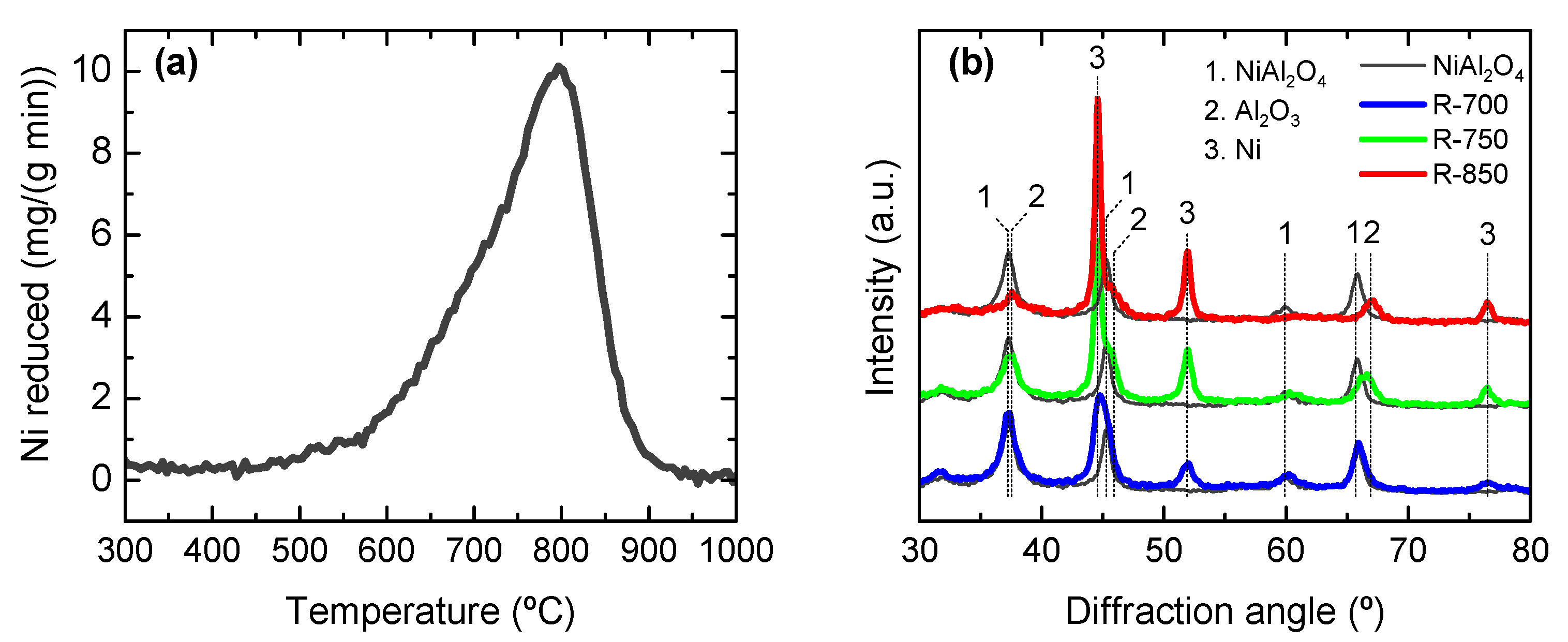
2.1. Fresh Catalyst Properties

Figure 1a shows the temperature programmed reduction (TPR) profile of the NiAl2O4 synthetized. The TPR profile evidences that the Ni reduction takes place between 500 and 900 °C with a maximum at 800 °C, characteristic of the reduction of Ni species in the spinel structure. Likewise, the absence of reduction peaks at lower temperatures indicates that no free nickel oxides are significantly present. This is verified by the XRD pattern (plotted in Figure 1b), evidencing the absence of NiO crystalline phases and the only presence of NiAl2O4 spinel. Thus, the reduction of all Ni species results in Ni crystals supported on Al2O3, which is possible at reduction temperatures above 850 °C for 4 h [19]. Likewise, the Ni content calculated from the TPR profile is 34.7 wt% in NiAl2O4 or 38.7 wt% in Ni/Al2O3, being very close to the stoichiometric values of 33.2 and 36.5 wt%, respectively.
The catalysts have been prepared by reducing the NiAl2O4 spinel precursor at 700, 750 and 850 °C, and they are named according to their reduction temperature, as R-700, R-750 and R-850, respectively. These catalysts have been characterized by several techniques to determine their more relevant properties. Figure 1b shows the X-ray diffraction (XRD) patterns of the catalysts and the NiAl2O4 precursor to determine the crystalline phases present in each material. The NiAl2O4 shows diffraction peaks at 2θ = 37.2, 45.3, 59.9 and 65.7° corresponding to a typical spinel cubic structure (PDF 01-071-0965) [21,23]. Upon reduction at 850 °C, the NiAl2O4 is almost completely converted into reduced Ni crystals (2θ = 44.6, 51.9 and 76.5°) (PDF 04-010-6148) and Al2O3 (2θ = 37.5, 45.9 and 66.9°) (PDF 04-005-4662), being a Ni/Al2O3 catalyst (R-850). In contrast, the catalysts obtained upon reduction at 700 °C (R-700) or 750 °C (R-750) show peaks of the NiAl2O4, reduced Ni crystals and Al2O3, indicating that a partial Ni reduction takes place since the reduction temperature is insufficient for a complete reduction according to the TPR data (Figure 1a). Thus, these catalysts are composed of reduced Ni crystals supported on NiAl2O4 and Al2O3 (Ni/Al2O3-NiAl2O4 catalysts). The average Ni crystal size was determined from the XRD data using the Scherrer equation (with diffraction peak at 51.9°), and the results (listed in Table 1) show that the Ni crystal size increases with increasing reduction temperatures. Likewise, the content of reduced Ni crystals was estimated from the TPR data according to the reduction temperature employed, and the results (listed in Table 1) confirm that this content increases with increasing reduction temperatures, as expected. Therefore, the decrease in the reduction temperature leads to a lower content of reduced Ni crystals but it also shortens the extent of Ni sintering, which results in lower average Ni crystal sizes.
The textural properties listed in Table 1 also evidence the effect of the transition of the NiAl2O4 spinel to Ni/Al2O3-NiAl2O4 catalysts. Accordingly, the specific surface area (SBET) decreases with increasing reduction temperatures, whereas the total pore volume (Vpore) and average pore diameter (Dpore) increase. The catalyst acidity was determined by means of NH3 adsorption, and the results are listed in Table 1. As seen, the acidity increases with increasing reduction temperatures from 0.026 mmol g−1 at 700 °C to 0.044 mmol g−1 at 850 °C, which should be related to the increasing Al2O3 content, with the presence of acidic γ-Al2O3 phases [21].
In summary, the reduction at 850 °C is sufficient to reduce all of the Ni species in the NiAl2O4 spinel and obtain a Ni/Al2O3 catalyst (R-850 catalyst), whereas the reduction at 700 and 750 °C partially reduces the Ni species in the NiAl2O4 spinel leading to obtain Ni/Al2O3-NiAl2O4 catalysts (R-700 and R-750 catalysts). Therefore, the contents of reduced Ni species (active for the ESR reaction) and acidic Al2O3 decrease as the reduction temperature decreases. In consequence, for the ESR reaction-regeneration cyclic tests, the space time is adjusted by using higher catalyst amounts when the reduction temperature is lower, for providing similar amount of reduced Ni species in the catalytic bed with the purpose of obtaining comparable values of ethanol conversion and H2 yield.

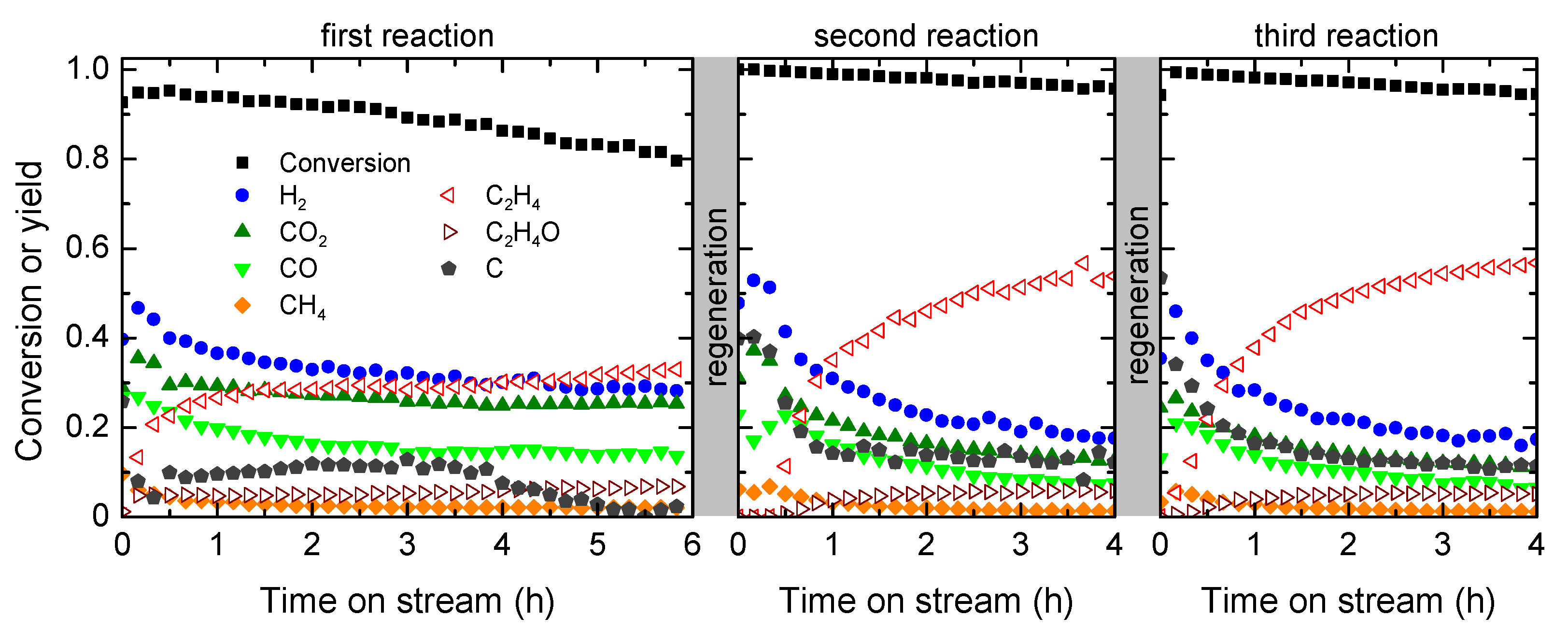
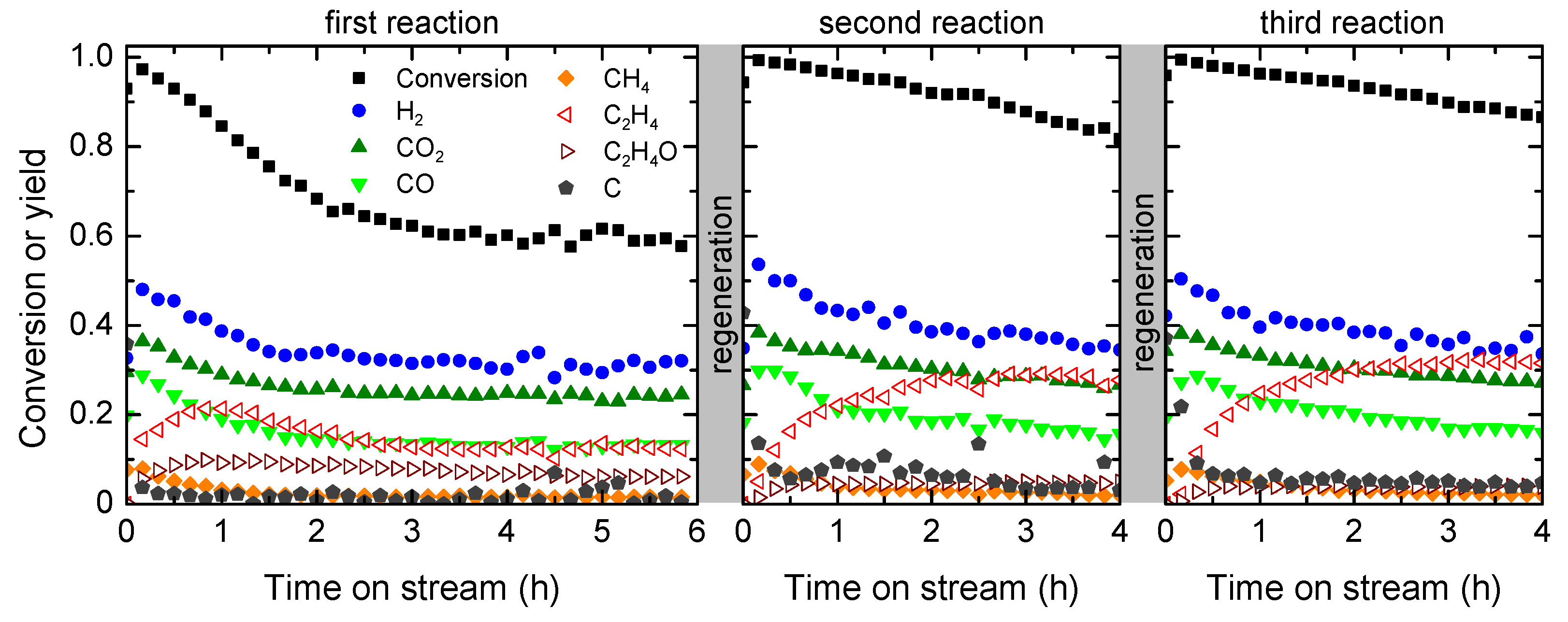
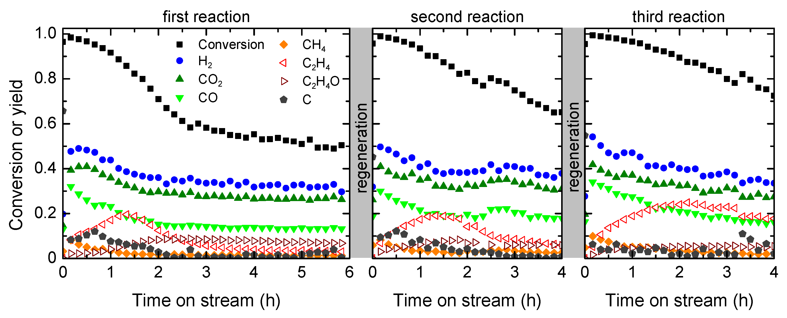
2.2. Catalyst Performance in ESR Reaction-Regeneration Cycles

The performance of the catalysts in reaction-regeneration cycles was studied quantifying the time on stream (TOS) evolution of the ethanol conversion and product yields for the ESR using the R-850 (Figure 2), R-750 (Figure 3) and R-700 (Figure 4) catalysts. The main products observed are H2, CO, CO2, CH4, and C2H4 and carbon deposited on the catalyst. The carbon yield was estimated from C balance taking into account the carbonaceous components in the feed and effluent streams.
Comparing the performance of the catalysts in the first reaction, the initial ethanol conversion and H2, CO, CO2, CH4 and C2H4 yields are similar. The TOS evolution of the H2, CO, CO2 and CH4 yields is also quite similar for the three catalysts, showing a significant decrease in the first 2 h on stream and more stable behavior afterwards, which indicates a partial catalyst deactivation for the reactions forming these products. The ethanol conversion decreases faster and reaches lower values in the pseudo-stationary state as the reduction temperature decreases (in this catalyst order: R700 > R750 > R850). Above 4 h on stream, the three catalysts reach a pseudo-stable state with constant product yields, in particular that of H2. The data evidence that the deactivation rate for the H2 formation reactions is similar for the three catalysts. However, the TOS evolution of the C2H4 and carbon yields is different among the three catalysts. For the R-850 catalyst, the C2H4 and carbon yields increase with TOS and keep a stable behavior up to 4 h on stream and afterwards the C2H4 yield slightly increases coinciding with the decrease in the carbon yield. In contrast, for the R-700 and R-750 catalysts, the C2H4 yield increases, reaches a maximum value (much lower than the values observed for the R-850 catalyst) and decreases afterwards, whereas the carbon yield is negligible. The slower decrease and higher values in the ethanol conversion with increasing reduction temperatures is due to the higher presence of acidic Al2O3 (Table 1) that catalyzes the ethanol dehydration yielding more C2H4 [21].
Upon the first reaction, the corresponding spent catalyst was subjected to the regeneration procedure described in Section 4 (combustion with air at 850 °C for coke removal and reconstruction of the spinel, followed by spinel reduction with H2-N2 stream at different temperatures of 700, 750 or 850 °C for the R-700, R-750 and R-850 catalysts, respectively). The whole procedure is repeated for a third reaction and the results are also shown in Figure 2, Figure 3 and Figure 4. For the R-850 catalyst, the TOS evolution of the product yields completely changes from the first to the second and third reactions, with the product distribution of the second and third reactions being almost identical (reproducible behavior upon the regenerations). Accordingly, the initial H2, CO, CO2 and CH4 yields are almost comparable with those of the fresh catalyst, but they rapidly decrease with TOS reaching much lower values in the second and third reactions in comparison with the first reaction. Likewise, the C2H4 and carbon yields notably increase in the second and third reactions, making the ethanol conversion also increase in comparison with the first use of the catalyst.
In contrast, for the R-700 and R-750 catalysts, the initial values of H2, CO, CO2, and CH4 yields and their TOS evolutions in the second and third reactions are quite comparable with those of the first reaction for each catalyst. However, the TOS evolution of the C2H4 yield notably differs, with an increasing trend in the values and apparent prolonged period of the maximum value in the successive cycles, which makes the ethanol conversion also increase compared with the first reaction for each catalyst.
It should be noted that the H2 yield is almost constant upon 4 h on stream, whereas the yields of other products change as a consequence of a partial catalyst deactivation for the extent of various reactions (Equations (1)–(14)). This observation is consistent with the H2 formation mechanism on catalysts derived from a NiAl2O4 spinel proposed in a previous work [21]. Accordingly, the partial catalyst deactivation sequentially affects the H2 and carbon formation from ethylene (Equation (10)) that explains the increase in the C2H4 yield over TOS, and the ethanol dehydration (Equation (5)) that explains the maximum observed in the C2H4 yield in the R-700 and R-750 catalysts. The reforming reactions catalyzed by Ni sites keep constant the H2 yield, and these sites keep their accessibility for these reactions since they also catalyze the carbon gasification [24].

2.3. Catalyst Characterization after Reaction-Regeneration Cycles

The catalysts were characterized after the third reaction using several techniques with the purpose of evaluating the carbon deposition and the recovery of the catalyst properties.

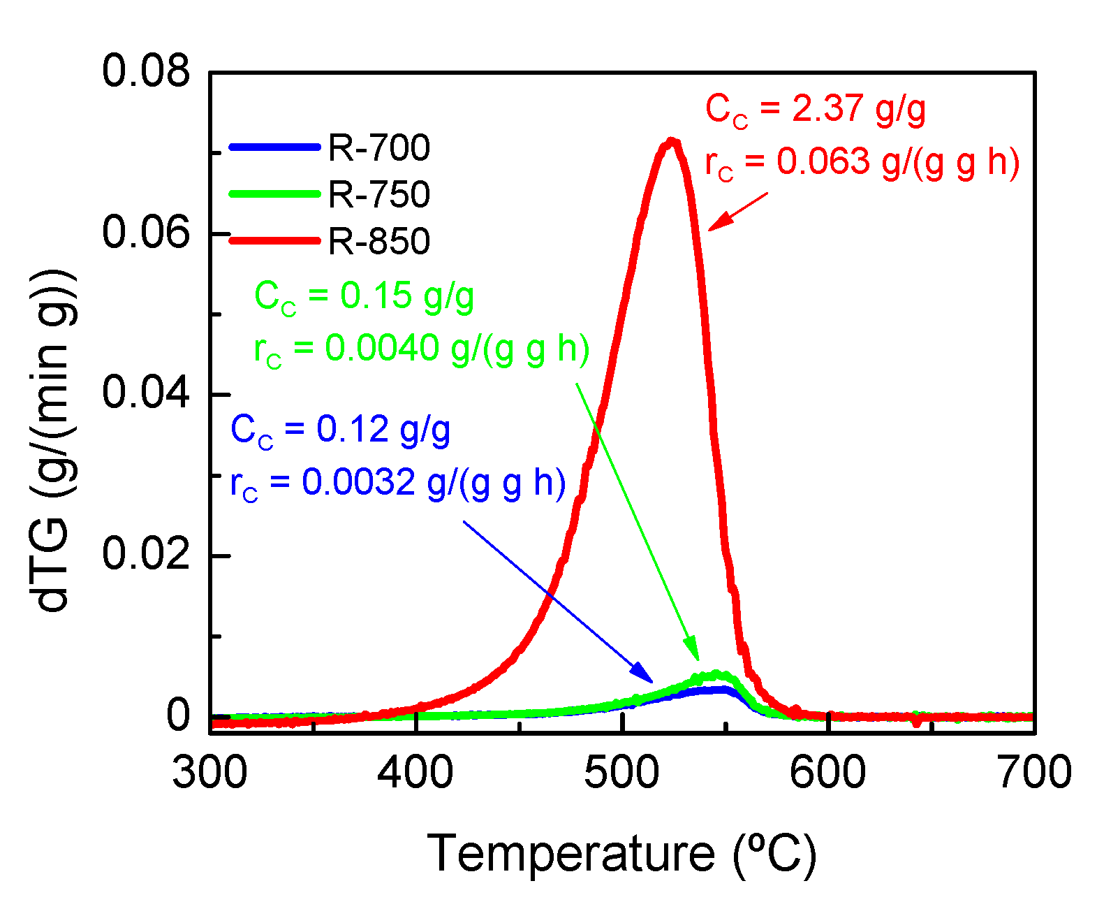
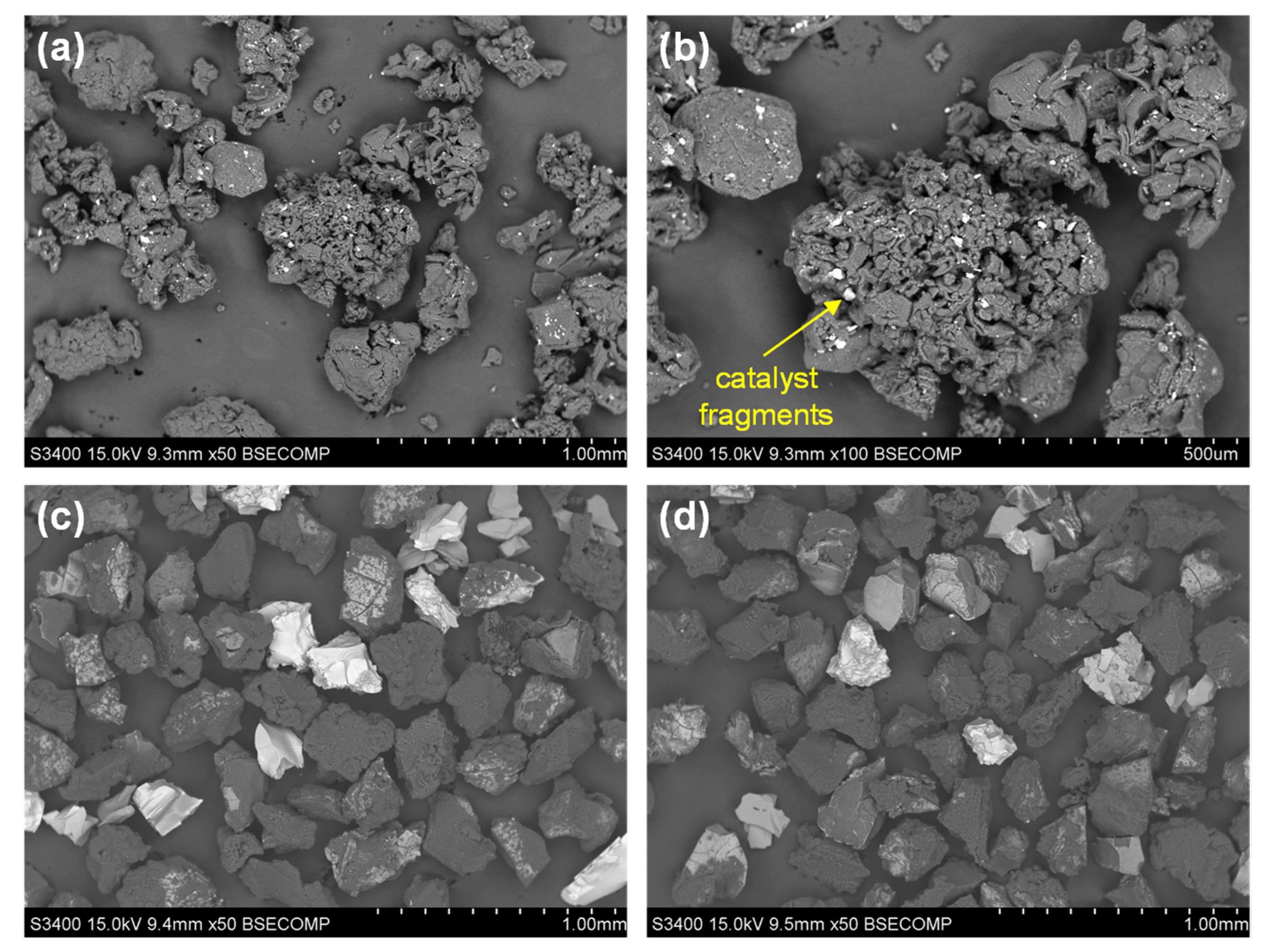
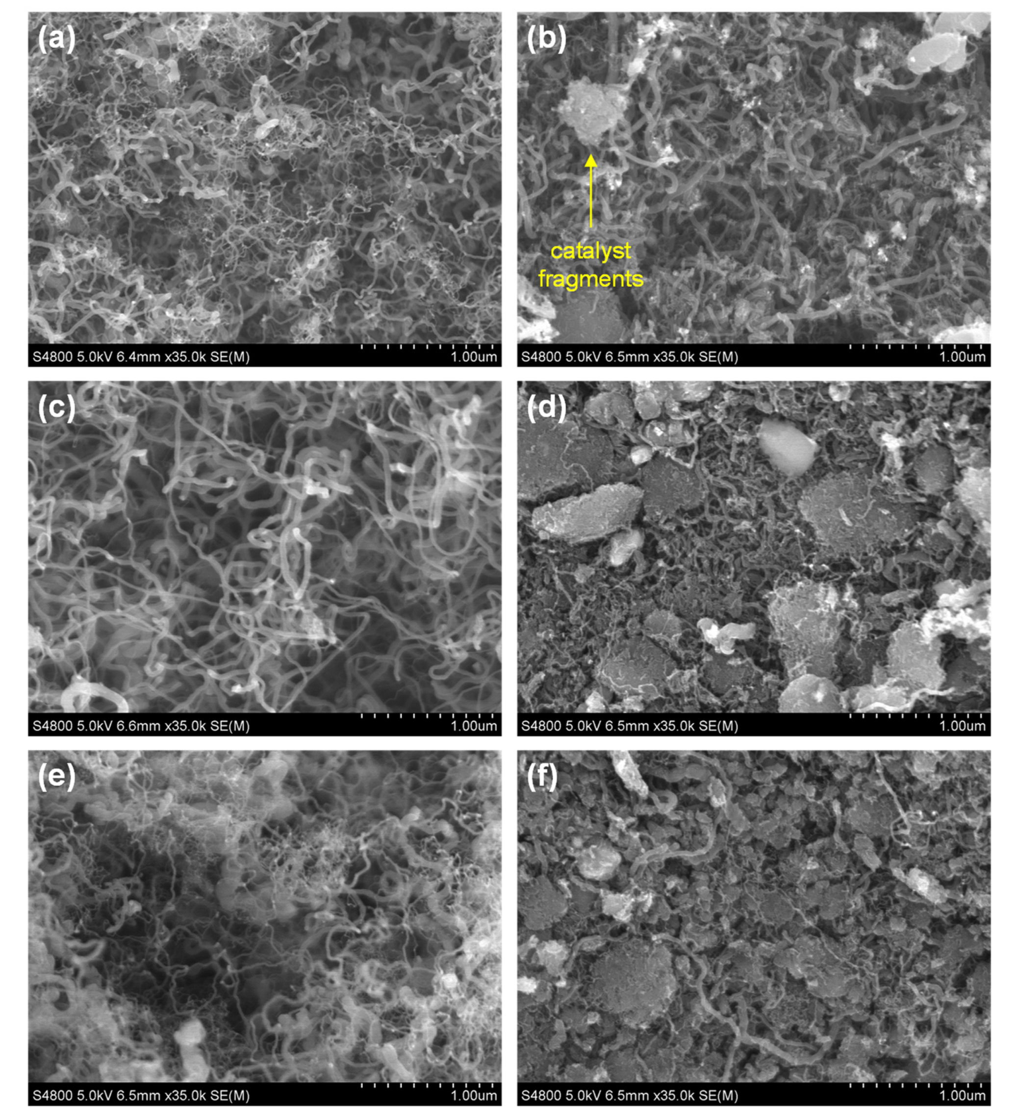
2.3.1. Carbon Deposition

The content and combustion characteristics of deposited carbon were determined by subjecting samples of the spent catalysts to temperature programmed oxidation (TPO). Figure 5 shows the TPO profiles of the three spent catalysts after the third reaction, in which a unique combustion peak is observed for each catalyst. The deposited carbon starts to burn above 400 °C and most of the carbon species burn at 525 °C for the R-850 catalyst and at 545 °C for the R-700 and R-750 catalysts. Thus, the carbon content (estimated from the area of each TPO profile) is notoriously higher for the R-850 catalyst (2.37 g (g catalyst)−1) than for the R-700 (0.12 g (g catalyst)−1) or R-750 (0.15 g (g catalyst)−1) catalysts. The values of the average carbon formation rate (rC) [25,26], (also indicated in Figure 5) are significantly lower for R-700 and R-750 catalysts than for R-850 catalyst. Likewise, the high combustion temperature at the maximum combustion rate (maximum peak position in the TPO profile) indicates that the carbon deposited on the three catalysts is highly structured and condensed with a low H/C ratio, expectedly composed of carbon filaments [21,27]. The shift to higher combustion temperatures for the carbon formed on the R-700 and R-750 catalysts indicates that the carbon structures are more refractory than those formed on the R-850 catalyst [28].
To investigate the extent of carbon deposition and the carbon morphology, samples of the spent catalyst were analyzed by means of scanning electron microscopy (SEM) using a backscattered electron (BSE) or secondary electron (SE) detectors, with the equipment described in Section 4. Figure 6 shows the BSE-SEM images of the spent catalysts after the third reaction, which provide insights into the extent of carbon deposition on the catalyst particles according to the brightness intensity levels. All of the spent catalyst particles show a strong carbon deposition on the external surface based on the almost homogeneous dark color of all samples. Remarkably, the size and textural appearance of some R-850 catalyst particles (Figure 6a) notably changed in comparison with those of the R-700 and R-750 catalysts (Figure 6c,d). Some R-850 catalyst particles are larger than the fresh catalyst (0.15–0.25 mm) and with a highly rough and meso- and macro-porous texture characteristic of carbon structures. Likewise, some bright small fragments can be seen on the external surface (magnified in Figure 6b), which is indicative of the presence of catalyst fragments (Ni and Al would give this brightness intensity) over the carbon deposited. The particle sizes of the spent R-750 (Figure 6c) and R-700 (Figure 6d) catalysts did not significantly change by the carbon deposition.
Figure 7 shows the SE-SEM images providing more details of the carbon morphology by magnifying some areas of representative particles of each sample. The photos evidence that the formed and deposited carbon is mostly composed of carbon filaments as typically expected for the ESR [21,27,28,29], being particularly abundant in all of the spent R-850 catalyst particles (Figure 7a,b). An apparent catalyst fragment is captured in Figure 7b, suggesting these fragments are on the tip of carbon filaments. On the other hand, in the particles of the spent R-700 and R-750 catalysts, two different surface morphologies can be distinguished, one similar to that of the R-850 catalyst with abundant carbon filaments (Figure 7c,e) and another with an incipient presence of carbon filaments and apparent amorphous mass of carbon (Figure 7d,f).

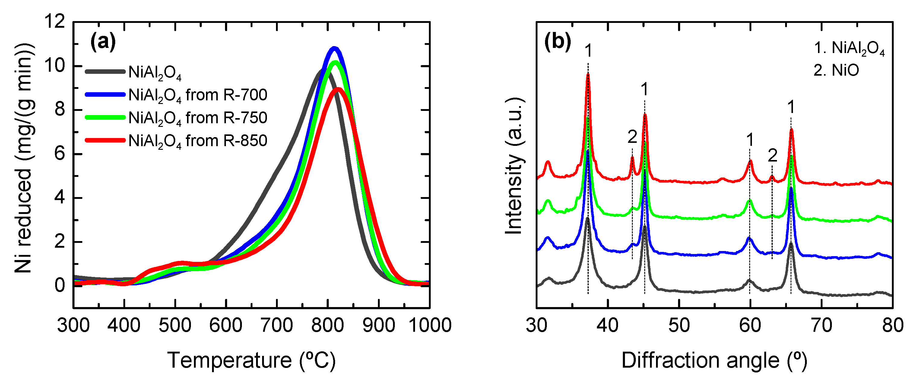
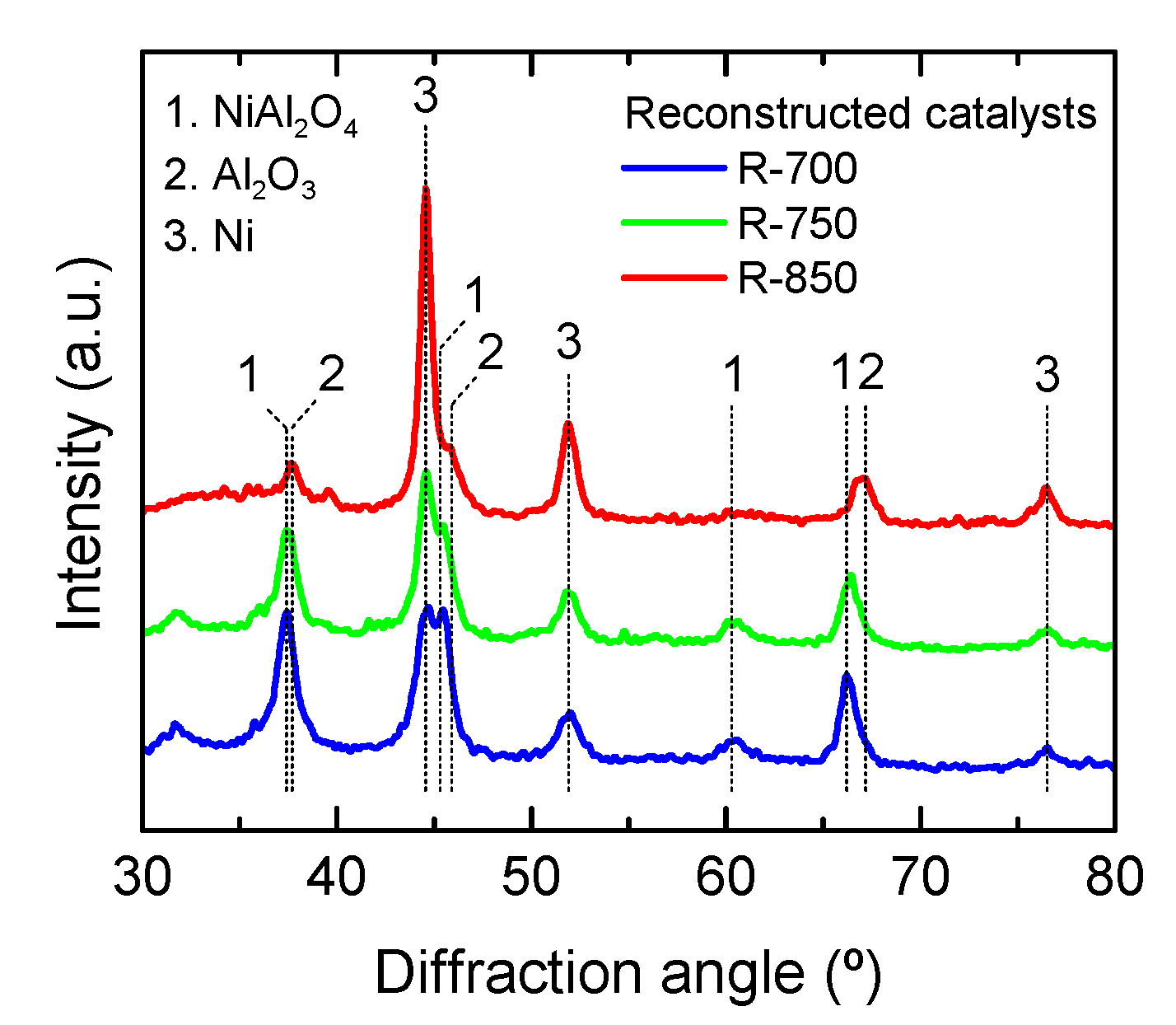
2.3.2. Regenerated Catalyst Properties

To verify the spinel reconstruction ability from the spent catalysts by combustion/calcination at 850 °C, samples of the reconstructed NiAl2O4 spinel from the used R-700, R-750 and R-850 catalysts were characterized by using TPR and XRD (Figure 8). The TPR profiles (Figure 8a) are compared with that of the NiAl2O4 precursor. In the reconstructed NiAl2O4 spinels, particularly from the used R-850 catalyst, the Ni reduction takes place in two temperature ranges, 400–600 and 600–950 °C, indicating the presence of two Ni species. The XRD patterns (Figure 8b) verify the presence of two crystalline phases, NiAl2O4 spinel (PDF 01-071-0965) and NiO (PDF 01-080-5508), being the spinel structure predominant in all of the samples and the presence of NiO more notorious in the spinel reconstructed from the spent R-850 catalyst. Thus, the Ni reduction at 400–600 °C may be associated to the reduction of NiO, whereas the Ni reduction in the NiAl2O4 spinel takes place at 600–950 °C with maxima at around 810–820 °C. Interestingly, the reduction peak and XRD peaks associated to the NiAl2O4 spinel tend to be narrower for the all of the reconstructed NiAl2O4 spinels than for the spinel precursor, which is indicative of more homogeneous NiAl2O4 structures. Likewise, the TPR profiles evidences that the total amount of reduced Ni (listed in Table 2) is lower for the reconstructed NiAl2O4 spinels than for the spinel precursor. Therefore, the decrease in the Ni content with respect to the fresh catalyst indicates a partial Ni loss after the ESR reaction cycles. These losses are 3.90, 9.50, and 14.5% for the R-700, R-750, and R-850 catalysts, respectively. Presumably, the Ni loss is due to the formation and volatilization of Ni(CO)4 during the combustion and spinel reconstruction at 850 °C. This carbonyl species formation is favored at this high combustion temperature and mainly affects the Ni crystals separated from the Al2O3 support that are on the tips or dispersed over the carbon filaments [30].
A sample of each reconstructed NiAl2O4 spinel was reduced at the corresponding temperature to obtain each regenerated catalyst. Figure 9 shows the XRD patterns of the regenerated catalysts after the third ESR reaction, which should be compared with those of Figure 1b (fresh catalysts). As seen, the R-700 and R-750 regenerated catalysts have phases of Al2O3 (PDF 04-005-4662), NiAl2O4 (PDF 01-071-0965), and reduced Ni crystals (PDF 04-010-6148), similar to the corresponding fresh catalysts (Figure 1b). The regenerated R-850 catalyst has Al2O3 and reduced Ni phases as in the corresponding fresh catalyst (in Figure 1b). Likewise, the peaks associated with NiAl2O4 in the XRD patterns of all of the regenerated catalysts (Figure 9) are more intense than those of the corresponding fresh catalysts (Figure 1b), suggesting that the reconstructed NiAl2O4 is more resistant to be reduced. This fact is also verified with the TPR profiles of the reconstructed NiAl2O4 spinels (Figure 8a), which shows that the maximum of the main reduction peak is shifted to higher temperatures in comparison with that of the NiAl2O4 spinel used as original precursor. Thus, it is reasonably expected that the amounts of reduced Ni in the regenerated catalysts (estimated from the TPR data and listed in Table 2) are slightly lower than those in the fresh catalysts (Table 1).
The textural properties (mainly SBET and Vpore) and the reduced Ni average crystal size are slightly lower for the regenerated catalysts with respect to the corresponding fresh catalysts. However, the slight change in these properties does not seem to affect the activity of the R-700 and R-750 catalysts upon regeneration and neither explains the low regeneration capacity of the R-850 catalyst.
To further investigate the state of the catalyst particles upon regeneration, we analyzed a sample of each regenerated catalyst using SE-SEM (Figure 10). The SE-SEM images reveal that the regenerated R-700 and R-750 catalysts (Figure 10a,b) keep the initial average catalyst particle size (between 0.15 and 0.25 mm), whereas the particles of the regenerated R-850 catalyst (Figure 10c) slightly decreased in size and some of them are powdered, which is clearly seen in the zoom of Figure 10d. This may be due to the catalyst fragmentation observed in this catalyst covered with abundant carbon species after the ESR reaction-regeneration cycles (Figure 6b and Figure 7b).

3. Discussion

The preparation of Ni catalysts from NiAl2O4 spinel using different reduction temperatures reports different performances in ESR reaction-regeneration cycles. At comparable ethanol conversion and H2 yield levels, the catalysts obtained by reducing at 700 and 750 °C (R-700 and R-750 catalysts, respectively) show a remarkable regeneration capacity as the performance in the second and third reactions is almost identical to that of the first reaction. Conversely, the R-850 catalyst obtained by reducing at 850 °C does not show this stability since the kinetic performance in the second and third reactions greatly differs from the first one, with a lower H2 yield. However, the R-850 catalyst is equilibrated upon the first reaction-regeneration cycle making its performance in the second and third reactions be outstandingly reproducible among them.
To investigate this behavior, we characterized the catalysts after the ESR reaction-regeneration cycles. The TPO results indicate that the R-850 catalyst produced much more carbon than the R-700 and R-750 catalysts, and the SE-SEM analysis shows that this carbon mainly grows in the form of filaments creating some fragmentation of the R-850 catalyst particles. This observation is reasonably explained by the lower acidity of the R-700 and R-750 catalysts, since it is well stablished that acidic supports promote the carbon formation and development of filamentous carbon structures in the ESR reaction [3].
Additionally, the reconstruction of the NiAl2O4 spinel from the used R-850 catalyst is notoriously incomplete resulting in a mixture of NiO and NiAl2O4 phases according to the XRD analysis, with a Ni content about 14.5% lower than in the synthesized spinel. The Ni loss also occurs in the reconstruction of the NiAl2O4 spinel from the R-700 and R-750 catalysts but to a lesser extent. This loss may be attributable to the formation of Ni(CO)4 that is volatized during the carbon combustion step [30], which may be expectedly favored at higher carbon contents. This is favored since some Ni crystals are separated from the Al2O3 support and swept along by the carbon filaments on the external surface of the catalyst particles, facilitating its volatilization by the Ni(CO)4 formation. However, the R-850 catalyst regeneration upon reduction of the reconstructed spinel results in a Ni/Al2O3 catalyst with little presence of NiAl2O4 (absence in the fresh catalyst), which is similar to the fresh R-850 catalyst in terms of the crystallographic analysis. Likewise, the textural properties and average size of reduced Ni crystals slightly decrease for the regenerated catalysts in comparison with the values for the corresponding fresh catalysts. However, none of these changes in the catalyst properties explains the low regeneration capacity of the R-850 catalyst, since the properties of the R-700 and R-750 catalyst are also affected to a similar extent and they showed an outstanding regeneration capacity.
Considering the aforementioned results, the explanation for the unsuccessful reactivation of the R-850 catalyst is the abundant filamentous carbon formation favored by the Al2O3 acidity. The growth of carbon filaments fragments the catalyst particles and favors the Ni loss. This fragmentation was evidenced by SE-SEM analysis of the regenerated R-850 catalyst particles, showing an overall reduction in the particle sizes and even the presence of catalyst powder. Therefore, the size of the regenerated catalyst particles ranges from powder (below 0.1 μm) to 0.25 mm. The collapse of the catalyst particles redistributes the Ni sites in the catalyst surface, causing a large amount of Ni sites to be exposed on the external surface of the multiple sized particles. These sites prone the formation and growth of carbon unconstrainedly, even trapping and possibly encapsulating the powder particles in the second reaction (after the first use of the catalyst). In fact, this is verified by the TOS evolution of carbon yield (Figure 2) in the second and third reaction, which evidences a higher and sustained carbon formation. Consequently, the amount of Ni sites available for the reaction is significantly lower since carbon formation reactions are favored, and therefore making impossible the complete recovery of the catalytic activity for steam reforming reactions.
The low presence of Al2O3 in the R-750 and R-700 catalyst explains the lower carbon formation and development of filaments on these catalysts, whose regeneration is feasible without a significant fragmentation of the catalyst particles. The lower coke deposition favors to reach a stable state in the activity of these catalysts since the carbon formation is partially suppressed and equilibrated with its gasification [20,21], avoiding the uncontrolled development of long carbon filaments.
These findings reveal that the amount of carbon formed and deposited on the catalyst determines the regeneration capacity of the Ni catalyst derived from NiAl2O4 spinel. In this work, the carbon formation was controlled by decreasing the catalyst acidity achieved by changing the reduction temperature at which the catalyst is obtained. In this way, the resulting catalyst consists of reduced Ni supported on Al2O3-NiAl2O4 at reduction temperatures of 700 or 750 °C, instead of reduced Ni on a pure Al2O3 support when using a reduction temperature of 850 °C, which would have more acidity. Thus, further strategies targeting at minimizing the carbon formation may be effective to improve the regeneration capacity of the catalyst for the ESR reaction-regeneration cyclic operation.

4. Materials and Methods

The catalysts were prepared by reduction of a NiAl2O4 spinel precursor with H2 at different temperatures. The NiAl2O4 spinel was synthesized by the co-precipitation of Ni(NO3)2 and Al(NO3)3 while dosing a NH4OH solution dropwise to increase the pH of the medium up to 8, following the procedure described in previous works [19,20,21]. The resulting precipitate is calcined at 850 °C for 4 h in a static air atmosphere to obtain the NiAl2O4 spinel and then crushed and sieved at 0.15–0.25 mm. The catalyst is obtained by reduction of the NiAl2O4 spinel at 700, 750, and 850 °C for 1 h in H2-N2 flow (10 mol% H2) with a heating rate of 10 °C min−1 in the reaction system. The resulting catalysts are named according to the reduction temperatures as R-700, R-750, and R-850.
The NiAl2O4 spinel and catalysts were characterized using X-ray diffraction (XRD), temperature programed reduction (TPR), N2 physisorption and NH3 adsorption, whose experimental procedures are described elsewhere [20,21]. The structural phases detected by XRD were identified using the database of the International Center for Diffraction Data by matching with the appropriate Powder Diffraction File version 4 (PDF-4). Additionally, the spent catalysts were characterized using temperature programed oxidation (TPO) as described elsewhere [21], and scanning electron microscopy (SEM) using a secondary electron (SE) detector in a Hitachi S-4800 N field emission gun scanning electron microscope (FEGSEM), and using a backscattered electron detector in a Hitachi S-3400 N microscope.
The reduction treatment and ESR reaction-regeneration cyclic tests were carried out in the reaction system (Microactivity reference-PID Eng and Tech) described in a previous work [21]. Briefly, the setup is provided with an isothermal fluidized bed reactor (22 mm internal diameter and total length of 460 mm) inside a furnace, and this arrangement (reactor and furnace) is inside a hotbox kept at 150 °C. The catalytic bed in the reactor consists of a mixture of an inert material (SiC from VWR Chemicals sieved at 105 μm) and the needed catalyst amount, keeping an initial height/diameter ratio above 2 for all of the experiments. The feed consists of a mixture of various gas streams (N2, H2 or air), each one controlled with mass flow meters, and a liquid stream (ethanol-water mixture) provided with a piston pump (Gilson 307). The mixing of the different feed components (gas or liquid streams) takes place in the hotbox kept at 150 °C to allow the evaporation of liquid components and preheating of the feed. The outlet stream from the reactor is sampled by taking a small amount through a capillary and the rest of the flow goes to a separator with a Peltier cooler where the vapor components are condensed and collected and the gas components are safely vented. The sample is mixed and carried with He to an Agilent 3000 micro gas chromatograph (micro-GC) through a thermally insulated line, for the component analysis. The micro-GC has four column modules for the detection and quantification of the reaction components: (1) molecular sieve capillary column for separating O2, N2, H2, CO, and CH4; (2) PLOT Q capillary column for separating light oxygenates and hydrocarbons (C1-C3), CO2, and water; (3) alumina capillary column for separating C2-C4 hydrocarbons; (4) Stabilwax type column for separating oxygenates (C2+) and water.
The following procedure was applied for the ESR reaction-regeneration cyclic tests upon loading the desired amount of NiAl2O4 spinel in the reactor:
(1)
Reduction treatment by flowing a gas mixture of 10 mol% of H2 in N2 at 120 cm3 min−1 measured at standard temperature and pressure (STP) while heating at 10 °C min−1 up to the desired reduction temperature (700, 750, and 850 °C) and keeping isothermally for 1 h. Once the catalyst is reduced, the flow is switched to pure N2 at the desired flowrate for the ESR reaction and the reactor is cooled down to 600 °C.
(2)
ESR reaction at 600 °C for 6 h on stream by feeding to the reactor a mixture of ethanol and water (steam/ethanol ratio of 3) pumped at 2 (g ethanol) h−1 and diluted in N2, so that ethanol concentration is 5 mol%. During the reaction run, the effluent stream is continuously sampled to analyze the composition. The ethanol conversion is calculated as:
X = F E 0 F E F E 0
where FE0 is the ethanol flowrate in the feed and FE is the ethanol flowrate in the effluent stream. Likewise, the product yields are calculated as:
Y i = F i ν i F E 0
where Fi is the molar flowrate of the product i in the effluent stream and νi is the stoichiometry coefficient (6 for H2 according to Equation (3), 2 for CO, CO2 and CH4, and 1 for C2H4 and C2H4O). At the end of the reaction run, the ethanol-water feed is cut off and the reactor is cooled down to room temperature in N2 flow.
(3)
Carbon elimination from the spent catalyst by flowing air to the reactor at 100 cm3 min−1 (STP) at 850 °C for 4 h, which also reconstructs the NiAl2O4 spinel.
(4)
Cyclic tests by repeating steps 1 to 3. At the final cycle, the catalyst is removed from the reactor after the ESR reaction, without eliminating the carbon, to analyze the spent catalyst. The carbon content is analyzed using TPO as aforementioned, and the average carbon formation rate (rC) is calculated as [25,26]:
r C = m c a r b o n m c a t a l y s t m C 0 t
where mcarbon is the mass of carbon formed during the reaction, mcatalyst is the mass of catalyst used in the experiment, mC0 is the total mass of carbon fed in the reaction run, and t is the time on stream.

5. Conclusions

The reduction temperature used for developing the structure of Ni supported catalysts (Ni/Al2O3 or Ni/Al2O3-NiAl2O4) is a key condition when preparing catalysts from NiAl2O4 spinel precursors. At 850 °C, the Ni species are completely reduced and a catalyst consisting of Ni/Al2O3 is obtained, whereas at 700 or 750 °C, the Ni species are partially reduced resulting in Ni/Al2O3-NiAl2O4 catalysts with lower acidity due to the moderate presence of Al2O3 in the mixed support. The lower acidity in these catalysts decreases the ethylene formation rate and consequently the carbon formation, making these catalysts have an outstandingly regeneration capacity with a reproducible performance in successive reaction-regeneration cycles. Likewise, these catalysts reach a pseudo-stable state with a H2 yield of 40% (at 600 °C; steam/ethanol ratio in the feed of 3, ethanol partial pressure in the feed of 0.05 bar and space time of 0.05 h). Contrarily, the catalyst obtained upon reduction at 850 °C shows a poor regeneration capacity. The irreversible deactivation is due to the activity of acid sites in the Al2O3 support for the ethylene formation from ethanol and subsequent ethylene conversion into carbon filaments. The excessive growth of these filaments contributes to the fragmentation of the catalyst particles with redistribution of part of the Ni sites to the external surface and the Ni loss by volatilization in the form of Ni carbonyl species.
The strategy of reducing the NiAl2O4 spinel at 700–750 °C to achieve the catalyst regeneration is easy and reproducible, keeping the catalyst formulation simple, which is technically and economically feasible for industrial applications. These reduction conditions allow the ESR process to be reproducible in reaction-regeneration cycles, which is a relevant advance for the industrial scale-up of this process.

Author Contributions

Conceptualization, A.G.G. and J.V.; methodology, S.I.-V. and J.V.; validation, A.R.; A.G.G. and J.B.; formal analysis, J.V.; investigation, S.I.-V. and J.V.; data curation, S.I.-V. and J.V.; writing—original draft preparation, J.V.; writing—review and editing, S.I.-V.; A.G.G. and J.B.; visualization, S.I.-V. and J.V.; supervision, A.G.G.; funding acquisition, A.G.G. and J.B. All authors have read and agreed to the published version of the manuscript.

Funding

This research was funded by the Ministry of Science and Innovation of the Spanish Government (grant RTI2018-100771-B-I00 and PhD grant BES-2019-090943 for S.I.-V. funded by MCIN/AEI/10.13039/501100011033 and by “ERDF A way of making Europe”); the European Commission (HORIZON H2020-MSCA RISE 2018. Contract No. 823745); the Department of Education, Universities and Investigation of the Basque Government, grant number IT1645-22.

Data Availability Statement

Not applicable.

Acknowledgments

The authors thank for technical and human support provided by SGIker (UPV/EHU/ERDF, EU).

Conflicts of Interest

The funders had no role in the design of the study; in the collection, analyses, or interpretation of data; in the writing of the manuscript; or in the decision to publish the results.

References

  1. Abdin, Z.; Zafaranloo, A.; Rafiee, A.; Mérida, W.; Lipiński, W.; Khalilpour, K.R. Hydrogen as an energy vector. Renew. Sustain. Energy Rev. 2020, 120, 109620. [Google Scholar] [CrossRef]
  2. Lopes, J.V.M.; Bresciani, A.E.; Carvalho, K.M.; Kulay, L.A.; Alves, R.M.B. Multi-criteria decision approach to select carbon dioxide and hydrogen sources as potential raw materials for the production of chemicals. Renew. Sustain. Energy Rev. 2021, 151, 111542. [Google Scholar] [CrossRef]
  3. Ogo, S.; Sekine, Y. Recent progress in ethanol steam reforming using non-noble transition metal catalysts: A review. Fuel Process. Technol. 2020, 199, 106238. [Google Scholar] [CrossRef]
  4. Sanchez, N.; Ruiz, R.; Hacker, V.; Cobo, M. Impact of bioethanol impurities on steam reforming for hydrogen production: A review. Int. J. Hydrogen Energy 2020, 45, 11923–11942. [Google Scholar] [CrossRef]
  5. Carapellucci, R.; Giordano, L. Steam, dry and autothermal methane reforming for hydrogen production: A thermodynamic equilibrium analysis. J. Power Sources 2020, 469, 228391. [Google Scholar] [CrossRef]
  6. Shtyka, O.; Dimitrova, Z.; Ciesielski, R.; Kedziora, A.; Mitukiewicz, G.; Leyko, J.; Maniukewicz, W.; Czylkowska, A.; Maniecki, T. Steam reforming of ethanol for hydrogen production: Influence of catalyst composition (Ni/Al2O3, Ni/Al2O3–CeO2, Ni/Al2O3–ZnO) and process conditions. React. Kinet. Mech. Catal. 2021, 132, 907–919. [Google Scholar] [CrossRef]
  7. Anil, S.; Indraja, S.; Singh, R.; Appari, S.; Roy, B. A review on ethanol steam reforming for hydrogen production over Ni/Al2O3 and Ni/CeO2 based catalyst powders. Int. J. Hydrogen Energy 2022, 47, 8177–8213. [Google Scholar] [CrossRef]
  8. Nanda, S.; Rana, R.; Zheng, Y.; Kozinski, J.A.; Dalai, A.K. Insights on pathways for hydrogen generation from ethanol. Sustain. Energy Fuels 2017, 1, 1232–1245. [Google Scholar] [CrossRef]
  9. Zhao, W.; Carey, S.J.; Mao, Z.; Campbell, C.T. Adsorbed Hydroxyl and Water on Ni(111): Heats of Formation by Calorimetry. ACS Catal. 2018, 8, 1485–1489. [Google Scholar] [CrossRef]
  10. Mueanngern, Y.; Li, C.-H.; Spelic, M.; Graham, J.; Pimental, N.; Khalifa, Y.; Jinschek, J.R.; Baker, L.R. Deactivation-free ethanol steam reforming at nickel-tipped carbon filaments. Phys. Chem. Chem. Phys. 2021, 23, 11764–11773. [Google Scholar] [CrossRef]
  11. Ochoa, A.; Bilbao, J.; Gayubo, A.G.; Castaño, P. Coke formation and deactivation during catalytic reforming of biomass and waste pyrolysis products: A review. Renew. Sustain. Energy Rev. 2020, 119, 109600. [Google Scholar] [CrossRef]
  12. Hu, X.; Zhang, Z.; Gholizadeh, M.; Zhang, S.; Lam, C.H.; Xiong, Z.; Wang, Y. Coke formation during thermal treatment of bio-oil. Energy Fuels 2020, 34, 7863–7914. [Google Scholar] [CrossRef]
  13. Zhao, X.; Lu, G. Improving catalytic activity and stability by in-situ regeneration of Ni-based catalyst for hydrogen production from ethanol steam reforming via controlling of active species dispersion. Int. J. Hydrogen Energy 2016, 41, 13993–14002. [Google Scholar] [CrossRef]
  14. Montero, C.; Remiro, A.; Arandia, A.; Benito, P.L.; Bilbao, J.; Gayubo, A.G. Reproducible performance of a Ni/La2O3–αAl2O3 catalyst in ethanol steam reforming under reaction–regeneration cycles. Fuel Process. Technol. 2016, 152, 215–222. [Google Scholar] [CrossRef]
  15. Campos, C.H.; Pecchi, G.; Fierro, J.L.G.; Osorio-Vargas, P. Enhanced bimetallic Rh-Ni supported catalysts on alumina doped with mixed lanthanum-cerium oxides for ethanol steam reforming. Mol. Catal. 2019, 469, 87–97. [Google Scholar] [CrossRef]
  16. Contreras, J.L.; Figueroa, A.; Zeifert, B.; Salmones, J.; Fuentes, G.A.; Vázquez, T.; Angeles, D.; Nuño, L. Production of hydrogen by ethanol steam reforming using Ni–Co-ex-hydrotalcite catalysts stabilized with tungsten oxides. Int. J. Hydrogen Energy 2021, 46, 6474–6493. [Google Scholar] [CrossRef]
  17. Boudadi, K.; Bellifa, A.; Márquez-Álvarez, C.; Cortés Corberán, V. Nickel catalysts promoted with lanthanum for ethanol steam reforming: Influence of support and treatment on activity. Appl. Catal. A Gen. 2021, 619, 118141. [Google Scholar] [CrossRef]
  18. Di Michele, A.; Dell’Angelo, A.; Tripodi, A.; Bahadori, E.; Sànchez, F.; Motta, D.; Dimitratos, N.; Rossetti, I.; Ramis, G. Steam reforming of ethanol over Ni/MgAl2O4 catalysts. Int. J. Hydrogen Energy 2019, 44, 952–964. [Google Scholar] [CrossRef] [Green Version]
  19. Arandia, A.; Remiro, A.; García, V.; Castaño, P.; Bilbao, J.; Gayubo, A. Oxidative Steam Reforming of Raw Bio-Oil over Supported and Bulk Ni Catalysts for Hydrogen Production. Catalysts 2018, 8, 322. [Google Scholar] [CrossRef] [Green Version]
  20. García-Gómez, N.; Valecillos, J.; Remiro, A.; Valle, B.; Bilbao, J.; Gayubo, A.G. Effect of reaction conditions on the deactivation by coke of a NiAl2O4 spinel derived catalyst in the steam reforming of bio-oil. Appl. Catal. B Environ. 2021, 297, 120445. [Google Scholar] [CrossRef]
  21. Valecillos, J.; Iglesias-Vázquez, S.; Landa, L.; Remiro, A.; Bilbao, J.; Gayubo, A.G. Insights into the Reaction Routes for H2 Formation in the Ethanol Steam Reforming on a Catalyst Derived from NiAl2O4 Spinel. Energy Fuels 2021, 35, 17197–17211. [Google Scholar] [CrossRef] [PubMed]
  22. Remiro, A.; Arandia, A.; Oar-Arteta, L.; Bilbao, J.; Gayubo, A.G. Regeneration of NiAl2O4 spinel type catalysts used in the reforming of raw bio-oil. Appl. Catal. B Environ. 2018, 237, 353–365. [Google Scholar] [CrossRef]
  23. Morales-Marín, A.; Ayastuy, J.L.; Iriarte-Velasco, U.; Gutiérrez-Ortiz, M.A. Nickel aluminate spinel-derived catalysts for the aqueous phase reforming of glycerol: Effect of reduction temperature. Appl. Catal. B Environ. 2019, 244, 931–945. [Google Scholar] [CrossRef]
  24. Ochoa, A.; Arregi, A.; Amutio, M.; Gayubo, A.G.; Olazar, M.; Bilbao, J.; Castaño, P. Coking and sintering progress of a Ni supported catalyst in the steam reforming of biomass pyrolysis volatiles. Appl. Catal. B Environ. 2018, 233, 289–300. [Google Scholar] [CrossRef]
  25. Ruocco, C.; Cortese, M.; Martino, M.; Palma, V. Fuel grade bioethanol reforming in a fluidized bed reactor over highly durable Pt-Ni/CeO2-SiO2 catalysts. Chem. Eng. Process. Process Intensif. 2022, 174, 108888. [Google Scholar] [CrossRef]
  26. Ruocco, C.; Palma, V.; Cortese, M.; Martino, M. Stability of bimetallic Ni/CeO2–SiO2 catalysts during fuel grade bioethanol reforming in a fluidized bed reactor. Renew. Energy 2022, 182, 913–922. [Google Scholar] [CrossRef]
  27. Quan, C.; Gao, N.; Wang, H.; Sun, H.; Wu, C.; Wang, X.; Ma, Z. Ethanol steam reforming on Ni/CaO catalysts for coproduction of hydrogen and carbon nanotubes. Int. J. Energy Res. 2019, 43, 1255–1271. [Google Scholar] [CrossRef]
  28. Ochoa, A.; Valle, B.; Resasco, D.E.; Bilbao, J.; Gayubo, A.G.; Castaño, P. Temperature programmed oxidation coupled with in situ techniques reveal the nature and location of coke deposited on a Ni/La2O3 -αAl2O3 catalyst in the steam reforming of bio-oil. ChemCatChem 2018, 10, 2311–2321. [Google Scholar] [CrossRef]
  29. Montero, C.; Remiro, A.; Valle, B.; Oar-Arteta, L.; Bilbao, J.; Gayubo, A.G. Origin and nature of coke in ethanol steam reforming and its role in deactivation of Ni/La2O3-αAl2O3 catalyst. Ind. Eng. Chem. Res. 2019, 58, 14736–14751. [Google Scholar] [CrossRef]
  30. Mihaylov, M.; Hadjiivanov, K.; Knözinger, H. Formation of Ni(CO)4 during the interaction between CO and silica-supported nickel catalyst: An FTIR spectroscopic study. Catal. Lett. 2001, 76, 59–63. [Google Scholar] [CrossRef]
Figure 1. Characterization of the NiAl2O4 precursor and catalysts obtained at different reduction temperatures. (a) TPR profile of the NiAl2O4; (b) XRD patterns of the NiAl2O4 and catalysts.
Catalysts 12 00550 g001
Figure 2. TOS evolution of the ethanol conversion and products yield with R-850 catalyst in ESR reaction-regeneration cycles.
Catalysts 12 00550 g002
Figure 3. TOS evolution of the ethanol conversion and products yield with R-750 catalyst in ESR reaction-regeneration cycles.
Catalysts 12 00550 g003
Figure 4. TOS evolution of the ethanol conversion and products yield with R-700 catalyst in ESR reaction-regeneration cycles.
Catalysts 12 00550 g004
Figure 5. TPO profile of the three spent catalysts after the third ESR reaction. CC is the carbon content referred to the catalyst mass and rC is the carbon formation rate referred to the catalyst mass, C mass fed, and time on stream.
Catalysts 12 00550 g005
Figure 6. BSE-SEM images of the catalyst particles after the third ESR reaction: (a) R-850 catalyst (×50); (b) R-850 catalyst (×100); (c) R-750 catalyst (×50); (d) R-700 catalyst (×50).
Catalysts 12 00550 g006
Figure 7. SE-SEM images of the catalyst particles after the third ESR reaction: (a,b) R-850 catalyst; (c,d) R-750 catalyst; (e,f) R-700 catalyst.
Catalysts 12 00550 g007
Figure 8. Characterization of the reconstructed NiAl2O4 spinels from the spent R-700, R-750 and R-850 catalysts and the spinel precursor: (a) TPR profile of the precursor and reconstructed NiAl2O4 spinels; (b) XRD patterns of the precursor and reconstructed NiAl2O4 spinels.
Catalysts 12 00550 g008
Figure 9. XRD patterns of regenerated R-700, R-750, and R-850 catalysts.
Catalysts 12 00550 g009
Figure 10. SE-SEM images of the regenerated catalyst particles: (a) R-700 catalyst (×100); (b) R-750 catalyst (×100); (c) R-850 catalyst (×100); (d) R-850 catalyst (×35,000).
Catalysts 12 00550 g010
Table 1. Main properties of the NiAl2O4 spinel and derived catalysts at different reduction temperatures.
SampleNi Content
(wt%)
Reduced Ni 1
(wt%)
SBET
(m2 g−1)
Vpore
(cm3 g−1)
Dpore
(nm)
Ni Crystal Size
(nm)
Acidity
(mmol g−1)
NiAl2O4 spinel34.7 **-78.30.1778.50--
R-700 catalyst38.7 *11.876.70.19710.59.100.026
R-750 catalyst38.7 *17.774.00.20510.912.00.029
R-850 catalyst38.7 *38.770.30.21212.617.00.044
SBET, specific surface area calculated using the Brunauer-Emmett-Teller (BET) theory; Vpore, total volume of pores; Dpore, average pore diameter. * Amount of reduced Ni in the Ni/Al2O3 or Ni/Al2O3-NiAl2O4 catalyst. ** Amount of Ni in the NiAl2O4 spinel. 1 Estimated from the TPR data.
Table 2. Main properties of the regenerated catalysts.
Regenerated CatalystsTotal Ni 1
(wt%)
Reduced Ni 1,2
(wt%)
SBET
(m2 g−1)
Vpore
(cm3 g−1)
Dpore
(nm)
Ni crystal Size
(nm)
R-70037.28.3049.00.23219.07.10
R-75035.012.546.40.17815.38.70
R-85033.130.142.70.16215.110.9
1 Amount of Ni in the Ni/Al2O3 or Ni/Al2O3-NiAl2O4 catalyst. 2 Estimated from the TPR data.
Publisher’s Note: MDPI stays neutral with regard to jurisdictional claims in published maps and institutional affiliations.

