
Recent Advances in Carbon-Silica Composites: Preparation, Properties, and Applications
by
 , and
, and
Tianhao Wu
1,2, 
Quanli Ke
1,*,
Mei Lu
3,
Pengyun Pan
1,
Ying Zhou
1,
Zhenyu Gu
2,
Guokai Cui
1 and
and
Hanfeng Lu
1,* 1
Institute of Catalytic Reaction Engineering, College of Chemical Engineering, Zhejiang University of Technology, Hangzhou 310014, China
2
Key Laboratory of Environmental Pollution Control Technology Research of Zhejiang Province, Eco-Environmental Science Research & Design Institute of Zhejiang Province, Hangzhou 310007, China
3
Zhejiang Environmental Technology Co., Ltd., Hangzhou 311121, China
*
Authors to whom correspondence should be addressed.
Catalysts 2022, 12(5), 573; https://0-doi-org.brum.beds.ac.uk/10.3390/catal12050573
Submission received: 31 March 2022
/
Revised: 8 May 2022
/
Accepted: 16 May 2022
/
Published: 23 May 2022
(This article belongs to the Special Issue Catalytic Conversion of Cellulose and Lignin)
Abstract
:The thermal catalytic conversion of biomass is currently a prevalent method for producing activated carbon with superb textural properties and excellent adsorption performance. However, activated carbon suffers severely from its poor thermal stability, which can easily result in spontaneous burning. In contrast, silica material is famed for its easy accessibility, high specific surface area, and remarkable thermal stability; however, its broader applications are restricted by its strong hydrophilicity. Based on this, the present review summarizes the recent progress made in carbon-silica composite materials, including the various preparation methods using diverse carbon (including biomass resources) and silica precursors, their corresponding structure–function relationship, and their applications in adsorption, insulation, batteries, and sensors. Through their combination, the drawbacks of the individual materials are circumvented while their original advantages are maintained. Finally, several bottlenecks existing in the field of carbon-silica composites, from synthesis to applications, are discussed in this paper, and possible solutions are given accordingly.

1. Introduction
1.1. Carbon Material
Carbon materials are universally used in different fields, including in catalysis, adsorption, and sensors [1,2,3]. The carbon family includes carbon fiber, carbon dot, graphene, carbon nanotubes, etc., which have diverse sizes, morphologies, and structure porosities [4]. The resultant desirable properties, e.g., high specific surface area, chemical stability, and excellent electrical conductivity, may also be at the heart of why carbon materials have recently attracted broad attention [5]. In consideration of the sustainable development of materials, carbon is the second most abundant element in the biosphere next to oxygen. The combination of carbon and hydrogen could offer the basis for a renewable energy source—biomass. Similarly, carbon-based systems play an increasingly important role in emerging renewable energy utilization technologies, including electrodes for energy storage, heterogeneous catalysis, electro- and photo-catalysis, biofuels, etc. In addition, carbon materials have been widely adopted in gas and water purification. The great potential of carbon materials is also evidenced by some of the highest scientific awards in recent decades, for instance, the 1996 Nobel Prize in Chemistry (fullerenes) and the 2008 Kavli Prize in Nanoscience (carbon nanotubes). Therefore, the development and application of carbonaceous materials is experiencing rapid growth and is a very popular topic in material science [6]. The advantages and disadvantages of the referred carbon materials are summarized in Table 1.
1.1.1. Activated Carbon
Activated carbon is a general term for highly porous carbonaceous materials, which are disordered materials with small pores and large surface areas. Generally, activated carbon is obtained by the thermal decomposition and subsequent partial oxidation (i.e., activation) of organic precursors, both natural and synthetic. Activated carbon is considered as one of the most conventional and common porous materials [18,19]. It is recognized as an efficient adsorbent for both inorganic and organic contaminants [20]. Owing to its superior adsorption properties, it has been widely applied in solvent recovery, wastewater treatment, food processing, metal recovery, chemical and pharmaceutical industries, and catalysis [20]. Activated carbon can be prepared from nearly all carbonaceous materials; the most prevalent sources for activated carbon production are wood, coconut shell, coal, peat, etc. The characteristics of activated carbon depend significantly on the activation method and the variety of raw materials. At present, activated carbon can be prepared via physical and chemical activation methods, including acid or alkali treatment, biological modification, plasma treatment, ozone treatment, microwave treatment, and many other methods. [21]. Physical activation is the most common method for the preparation of activated carbon. In principle, there are two necessary stages in the physical activation of carbon—pyrolysis and activation. In the first stage, certain carbonaceous precursors are pyrolyzed under an inert or reducing gas atmosphere at moderate temperatures to release volatile species, which imparts carbons with a basic pore structure. Then the resulting intermediate is partially gasified with an oxidizing gas atmosphere (such as air, steam, carbon dioxide, or a mixture) at higher temperatures (usually above 900 °C) to obtain activated carbons with abundant and highly accessible porous structures [20]. When chemical activation is used to prepare activated carbon, the precursor is first impregnated in a solution of activating chemical reagent (such as ZnCl2, KOH, or H3PO4), followed by carbonization at a moderate temperature, and finally the residual activating chemical reagent in the material is removed and recovered by washing [22].
1.1.2. Carbon Nanotubes
Carbon nanotubes (CNT) are a carbon allotrope with cylindrical one-dimensional structures and high degree of structural integrity. Single-walled nanotubes (SWNTs) consist of a graphite sheet seamlessly wrapped in a cylindrical arrangement. Multi-walled nanotubes (MWNTs) consist of a series of these nanotubes nested concentrically like the rings of a tree trunk [18,23]. All carbon atoms of a perfect CNT are embedded in a hexagonal lattice, except for the ends; however, structure defects are frequently observed in the sidewalls of mass-produced CNTs, including pentagons, heptagons, and other morphologies, which often deteriorate their expected performance [24]. Even so, CNTs have received extensive attention since they were first reported in 1991. One of the most significant reasons for this is that CNTs provide a chemically inert surface for physical adsorption and have a large number of modifiable binding sites due to their hollow structure [21]. With regard to mechanical properties, nanotubes are currently one of the most rigid and elastic materials known. Nanotubes have a Young’s modulus of 1.2 TPa, which is almost 100 times stronger than that of steel, and can withstand great strains before final mechanical failure [25]. Given the excellent mechanical and physical properties of this new member of the carbon family, CNTs have now been established as an ideal model for investigating one-dimensional solid-state physics, serving as the building blocks for a variety of practical nanodevices [25]. In addition, CNTs have shown great potential in the manufacture of mechanical, chemical, electromechanical, and miniaturized electronic facilities, as well as in the synthesis of macroscopic composite materials [24]. As for CNT composite materials, most of them rely on disorganized CNT structures with limited performances [24]. Nonetheless, the regular CNT architecture is expected to expand the performance of individual CNTs and enable new functions, including shape recovery, high damping, terahertz polarization, thermoacoustic emission and near-ideal blackbody absorption, etc. [24].
1.1.3. Graphene
Graphene is a structure with a two-dimensional honeycomb arrangement of carbon atoms. It can be wrapped into zero-dimensional (0D) fullerene, rolled into one-dimensional (1D) nanotube, or stacked into three-dimensional (3D) graphite [26]. Since graphene was first made by mechanical exfoliation in 2004 [27], its excellent chemical and physical properties have attracted widespread interests. Currently, it is considered to be the thinnest carbon material in the world, and its unique two-dimensional honeycomb lattice structure offers great potential in many applications [28]. Their electron-rich and electrostatic-stacking properties, hydrophobicity and large specific surface area, easy functionalization with various groups, and composition of diverse materials all make graphene-based composites excellent adsorbents. Additionally, graphene also exhibits excellent light absorption properties, thermal conductivity, and mechanical strength, which is why it is used in many different instruments, including ultrafast photodetectors, single molecule detectors, ultrafast field-effect transistors (FETs), single bacteria/DNA detectors, hydrogen visualization templates for TEM, and tunable spintronic devices [28].
Generally, there are two main ways to make graphene. One is to mechanically split layered materials, such as graphite, into individual planes of atoms, which is how graphene was originally isolated [29]. Although this handcrafted process is delicate and time-consuming, it provides crystals with high structural and electronic quality, which can now be made into millimeter sizes. The other route involves the exfoliation of graphite layers that have previously been grown epitaxially on other crystals. This is a 3D growth, during which the epitaxial layer remains bonded to the underlying substrate, and the bond-breaking fluctuations are suppressed [29]. When the epitaxial growth is finished, the substrate can be removed by chemical etching. In addition, the top-down exfoliation of graphite by oxidation, intercalation, or ultrasonic treatment has also been developed [21,30]. Currently, the low-cost, large-scale production of chemically exfoliated graphene oxide (GO) and reduced graphene oxide (rGO) sheets has already been achieved. This is realized by the functionalization of the graphene surface with oxygen-containing functional groups (carboxyl, carbonyl, hydroxyl, etc.) and subsequent delamination by removing these groups on the edge and surface of the graphene oxide. As a result, the conjugated structure of graphene can be restored, while the active oxygen-containing groups can be used for the further functionalization and property-tuning of GO or rGO sheets [21,30].
1.2. Silica Material
Silicon is the second most abundant element in the earth’s crust, mostly found in the form of oxides and silicates. Silicon is a relatively inert element; however, it can react with halogens and dilute bases. Most acids have no effect on it, except for hydrofluoric acid. Meanwhile, silicon is one of the most useful elements in many industries, e.g., semiconductors, ceramics, building materials, glass, and organometallic silicones [31]. The advantages and disadvantages of the referred silica materials are summarized in Table 2.
1.2.1. Silica Gel
Silica gel is a commonly used adsorbent. Its success lies in the fact that it does not swell or deform during adsorption and has good mechanical strength and thermal stability. Due to its highly developed porous structure, it is often used as fluid dehumidizer, organic adsorbent, catalyst carrier, and fluid thixotropy enhancer [33]. Additionally, chelating agents can be readily loaded on (or chemically bound to) silica gel with high stability. Since a typical characteristic of the silica gel surface is the existence of silanol groups, which are weak sites for ion exchange, it has a low interaction (or binding force) with ionic species [32]. Meanwhile, it should also be noted that the wide application of silica gel depends on its preparation process and the resultant porosity; therefore, an appropriate preparation or additional modification process of silica gel is necessitated [38].
1.2.2. Mesoporous Silica
Porous materials are classified by IUPAC into three categories based on pore size: micropores (pore diameters within 0.2–2.0 nm); mesopores (pore diameters within 2.0–50.0 nm); and macropores (pore diameters larger than 50.0 nm). Microporous and macroporous materials cannot selectively adsorb large organic molecules due to their pore size distribution (size exclusion for microporous material and weak interaction for macroporous material). In contrast, mesoporous materials can not only guarantee the accessibility (during both adsorption and desorption) of molecules within the intermediate-sized pore channels, but also retain high selectivity and capacity by geometry and pore volume modification.
In recent years, because of the high pore volume and surface area of mesoporous silica materials, they have been widely utilized as supports, adsorbents, and catalysts. The demand for mesoporous silica materials has sparked a great deal of synthetic work [35]. In 1992, Mobil Corporation discovered the M41S series of mesoporous silica materials; later, in 1998, Zhao et al. [39] put forward an evaporation-induced self-assembly (EISA) method, wherein triblock copolymers (PEOn−PPOm−PEOn) were adopted to produce a series of mesoporous silica materials with a highly ordered structure, large pore size, and good stability. In addition to the bulky mesoporous silica materials, a growing demand in advanced application fields has brought about the development of mesoporous silica nanoparticles. The synthesis of mesoporous silica nanoparticles is based on the use of cationic surfactants as structure-directing agents (SDAs) to form a mixed organic-inorganic matrix, which is then subjected to calcination or surfactant extraction to generate mesoporous frameworks. The formation of micellar structures facilitates the establishment of siliceous frameworks through the polymerization of the silica precursors [40]. Due to the optical transparency of mesoporous silica materials in the visible and near-ultraviolet ranges, they are now used in optical applications, such as light filters, sensors, lasers, solar cells, optical data storage, nonlinear optics, and photocatalysts [35].
1.2.3. Molecular Sieve
Molecular sieves are high-crystalline aluminosilicates with well-defined and well-developed pore structures that are composed of SiO2 and AlO4 tetrahedra. A variety of materials with different topologies can be derived by the unique linking modes of these tetrahedra. Currently, more than 250 different topologies have been identified and assigned a three-letter code by the International Zeolite Association (IZA) [36]. Their chemical composition has now been extended to other atoms, including the non-metallic elements of boron and phosphorus, and the metals ones of tin, gallium, germanium, zinc and titanium. These atoms are tetrahedrally connected by sharing oxygen atoms (so-called TO2) to form an ordered framework with characteristic micropores in the form of channels and cages. Various types of active sites can be observed in molecular sieves: Lewis and Bronsted acids (in the framework or extra-framework), metal cations (compensating framework charges from isomorphic AlO2 substitution), and active nanoscale clusters (metals clusters, etc.) [41]. In addition, molecular sieves have regular microporous structures, adjustable active sites, large adsorption capacity, and excellent (hydro)thermal stability. All these features make molecular sieves excellent adsorbents with superior selectivity (shape and size exclusion) for small molecules, which can be used in a wide range of applications, including adsorption, ion exchange, catalysis, etc. [36,40].
As a crucial member of molecular sieves, zeolite (normally microporous aluminosilicate) can be further divided into small-pore, medium-pore, and large-pore zeolite. Typically, small-pore zeolite has a pore size range of 0.30–0.45 nm (eight-member ring window), while medium-pore zeolite has a pore size range of 0.45–0.60 nm (10-member ring window) and macro-pore zeolite has a pore size range of 0.60–0.80 nm (12-member ring window or above) [42]. Likewise, the ion-exchange and catalytic properties of zeolites can also be modified by changing the framework composition and extra-framework compensating cations. Since the pore size of classical zeolite is usually small, and the active sites may be buried in the cage structure of molecular sieves, it is difficult to exert its effect due to the shielding effect of the electric field of its framework oxygen atoms. Given this, Valtchev and coworkers [43] reported a method for the tunable removal of zeolite framework atoms in faujasite-type zeolites to increase their micropore volume by about 10%. The increase was due to the opening of relatively small sodalite cages, otherwise inaccessible for most molecules. The catalytic activity of these modified zeolites was significantly improved as more active centers became accessible. The method is based on NH4F etching and is also applicable to other cage-containing microporous zeolites, such as the famous MFI zeolite [44].
In order to promote the accessibility of active sites and enhance the diffusion of molecules, hierarchically porous zeolites are currently arousing interests. Verboekend and colleagues [45] mentioned in their review that although micropores in zeolites offer superior performance compared to amorphous aluminosilicates, they also limit mass transfer within zeolite crystals. Furthermore, crystals are not available for all kinds of bulky molecules, which are only able to react on their external surface. To alleviate these concerns, hierarchically porous zeolites were proposed. This type of material couples the secondary mesopores or macropores with the micropores, which enhances mass transportation and diffusion within the crystal, ideally while keeping the inherent zeolite properties. Pérez-Ramírez and colleagues [46] proposed a combination of acid and alkali treatments to prepare hierarchically porous zeolites. The choice of different starting zeolites and comprehensive post-synthesis modifications confirmed the paradoxical relationship between the sensitive zeolite framework and its high aluminum content. The textural results proved that the extraction of Al-rich fragments was crucial to the release of porosity and enhancement of crystallinity. Meanwhile, for aluminum-deficient zeolites, the inclusion of organic cations in the alkaline solution plays a significant role in slowing the dissolution of silicon atoms, resulting in hierarchically porous zeolites with retained crystallinity and micropores.
Historically, research on molecular sieves has primarily been stimulated by the chemical and petroleum industries. Common uses of molecular sieves include catalysts for petroleum cracking, adsorbents for heavy metals and air separation, and additives for animal feed. While advances in molecular sieves are still commercially driven, new research in this field has been reinvigorated by the advent of nanotechnology [47].
1.3. Research Hotspots in Porous Composites
Metal–organic frameworks (MOFs) basically consist of two main building units: an inorganic node, and an organic molecule, which are linked by coordination bonds. In general, the inorganic building units are metal ions or clusters, and the organic building units (called linking or bridging ligands) are di-, tri-, or tetradecanoic acid organic ligands, such as carboxylates and other organic anions (e.g., phosphonates, sulfonates, and heterocyclic compounds) [48]. The pore size and morphology of MOFs can be fine-tuned by changing the characteristics and connectivity of the inorganic moieties and organic linkers. Due to the facile modification of their pore structure and surface polarity, MOFs are one of the most promising materials for adsorption applications. Nonetheless, there are still some shortcomings that seriously hinder the potential applications of MOFs. On top of that, most MOFs are not resistant to water/steam, high temperatures, and strong electron beams. Therefore, their low stability strongly limits their upscale application, as material stability is urgently needed in many industrial processes. Secondly, the MOF crystals obtained through the traditional method are normally in powder form and have poor mechanical strength, and thus are not appropriate for subsequent processes.
To circumvent the above problems, the construction of MOF-based composites has attracted extensive attentions. Using this strategy, advantageous properties can be integrated while the unfavorable disadvantages of individual components be mitigated, leading to synergistic effects and new possibilities. At present, MOF–silica composites, MOF–metal composites, MOF–carbon composites, MOF–polyoxometalate composites, and MOF–organic polymer composites have been successfully synthesized. Among them, MOF–carbon composites (i.e., composites of MOFs and carbonaceous materials) are interesting because MOFs represent a state-of-the-art material, while carbonaceous materials are considered as a classical material. In particular, carbonaceous materials have different allotropes (activated carbon, fullerenes, graphite, nanotubes, etc.) and existing forms (powder, graphite, monolith, etc.). As a result, remarkable chemical and thermal robustness, excellent electronic and optical properties, low toxicity, and sometimes low cost can be simultaneously achieved [49].
1.4. Definition of Carbon-Silica Composites and Their Advantages
1.4.1. Definition of Carbon-Silica Composites
Similar to the MOF–carbon composite, the carbon-silica composite was also put forward to combine the merits and circumvent the drawbacks of its pristine components, resulting in a synergistic effect and new functions that the pristine parts did not possess. In theory, the carbon-silica composite should have a core-shell or layered morphology. Due to the microporous structure of carbon materials and the high thermal stability of silica, a composite should combine both their advantages. In some cases, when the carbon layer is decorated on the macroporous surface of silica material, the surface area and pore size distributions can also be adjusted.
1.4.2. Comparison of Carbon-Silica Composite with Other Porous Materials
As described above, carbon materials have attracted a great deal of interests because of their high electrical conductivity, low cost, and multiple forms. More importantly, their superior chemical stability in different conditions (from strong acids to bases) and capability to work in a wide temperature range increases the attractiveness of carbon materials [5]. However, carbon materials also suffer from severe drawbacks: the abundant micropores in carbon materials lead to the difficulty during desorption, and their vulnerable structure may be flammable under high temperature and cause safety issues [50,51].
In contrast, silica materials are advantageous due to their high porosity, thermal stability, and mechanical strength; however, their strong affinity to water derived from the presence of silanol groups on their surface could introduce competitive adsorption between water and reactant molecules and affect the adsorption or catalysis performances. For molecular sieves, specifically, the hydrophilicity problem still remains, while the desorption of organic molecules in the microporous structure can also be energy-consuming. As a new kind of porous material, MOFs have superior advantages, such as highly tunable porosity, easy functionalization, and highly porous structure, compared with traditional porous materials [52,53]. However, MOFs are frequently prone to bond cleavage under harsh conditions, including high temperature, high humidity, and organic solvents, which results in structural collapse [54]. Although composites of MOFs and carbon materials can partially relieve these concerns, thermal stability is still a problem under even harsher conditions. Under this consideration, composites of carbon and silica materials can circumvent their individual defects and combine their advantages, i.e., the silica material could enhance the thermal stability, while the carbon material could not only tune the porosity but also weaken the hydrophilicity. On this basis, the present review intends to summarize the different synthesis methods and resultant properties of carbon-silica composite materials, which could have promising applications in diverse fields that take advantage of their enhanced thermal stability and hydrophobicity. A general scheme is shown in Figure 1.
2. Synthetic Method
2.1. Hybrid Pyrolysis Carbonization
Pyrolysis is an endothermic process, and pyrolytic carbonization refers to the conversion of biomass or other organic matter into carbon materials by thermochemical decomposition under atmospheric pressure in an inert atmosphere (such as N2 or Ar) [55,56,57]. This preparation method involves the pyrolysis of organic precursors followed by carbonization, with the release of various hydrocarbon gaseous species, to obtain residues with high carbon content (carbonaceous residues). The pyrolysis of organic precursors and the carbonization of carbon-containing residues occur continuously; thus, pyrolysis and carbonization usually overlap with each other [58]. During the preparation process, the carbon precursor homogeneously mixed with the silica material is first carbonized by the pyrolysis treatment, while the silica material retains a relatively rigid structure during the carbonization process due to its high melting point. As the pyrolytic carbonization is completed, the two components of carbon and silica will be closely combined to form a carbon-silica composite material. The preparation conditions and resultant material properties of the carbon-silica composites prepared by the hybrid pyrolysis carbonization method are listed in Table 3.
Taking this synthetic strategy, Aranda et al. [62] reported a method for preparing carbon-silica foam using microwave irradiation to greatly shorten the preparation time without using a foaming agent and strong acid; this carbon-silica composite could be used to remove soluble toxic compounds in water pollution. Sucrose was used as the carbon precursor, and microporous silica gel was used as the inorganic carrier for the chemical conversion of sucrose. When the carbon and silica precursors were homogeneously mixed, the sucrose was initially converted into caramel by short-term microwave irradiation. The microwave irradiation time during the caramelization step was strictly controlled to avoid carbonization. The carbon/silica material was subsequently obtained by heat treatment (Figure 2). Notably, water plays a significant dual role in this process: first, it homogenizes the sucrose/silica mixture and makes it easier to convert sucrose to caramel, and second, a part of the water is adsorbed in the micropores of the silica, where the slow release of steam during heating contributes to the formation of macropores. In addition to acting as an adsorbent for water, the porous silica gel also serves as an adsorbent for volatile organic compounds generated during the thermal decomposition of carbon precursors. Once these volatile compounds become air bubbles, they can be used as a pore-forming agent for carbon-silica foam. In a similar way, Tomaszewski et al. [63] used silica gel as the carrier and potato starch as the carbon precursor to prepare a carbon-silica composite adsorbent and investigate the influence of structural characteristics on its solid-phase extraction performances for explosive nitramines. The textural results showed that the deposition of carbon nanoparticles on the silica gel led to a decrease in the pore volume but an enhanced proportion of micropores. In this way, the recovery rate of the explosive nitramines was also increased due to the more accessible surface area of the carbon phase. In addition to biomass precursors, other organics can also be adopted as the carbon precursors (e.g., dichloromethane or surfactant). For example, Gao et al. [64] prepared a mesoporous carbon-silica composite by carbonizing the cationic surfactant CTAB in mesoporous silica under 800 °C with the assistance of concentrated sulfuric acid. When using surfactant template as carbon source, the problems caused by using exogenous carbon sources, such as pore blocking and coating unevenness, can be avoided.
The volume expansion of silica-based materials during the charging and discharging process can lead to excessive capacity decay and poor conductivity, which is adverse to rapid charging and discharging. For this reason, Xing et al. [65] successfully prepared a new type of silica-based material using a simple pyrolysis strategy to solve the volume expansion problem. By virtue of this strategy, nitrogen doping and carbon nanosheet coating on a silica precursor could be simultaneously realized in one step. Firstly, silica nanoparticles of different sizes were prepared by the hydrolysis and condensation reaction of TEOS; then, a certain amount of anhydrous glucose, dicyandiamide, and silica nanosphere powder were ground. The obtained white slurry was then dried and calcined in a protection atmosphere, and a nitrogen-doped carbon nanosheet–silica composite material was finally obtained. Through this method, the particle size of the synthesized silica nanospheres could be well controlled while the size-controllable nanosilica spheres were embedded into the carbon nanosheets, which greatly enhanced the electronic conductivity of the composite. In addition, the existence of carbon nanosheets could also serve as a buffer layer to effectively alleviate the volume expansion of electrode materials during delithiation (wherein Li ions depart from the electrode and dissolve into the electrolyte) and intercalation (wherein Li ions move from the electrolyte to the lattice of the electrode). In addition to the high capacity of silica, a moderate doping of nitrogen in the graphitic matrix further improved the Li-ion storage performance and electron transfer rate of the composites [65].
Thermal stability is a long-standing bottleneck in the application of traditional activated carbon. In order to solve the safety problem during the use of activated carbon, Kong et al. [66] prepared a carbon-silica composite material by extrusion molding and heat treatment over a commercial activated carbon, sodium silicate, and sodium carboxymethyl cellulose mixture. First, the powdered activated carbon and sodium carboxymethyl cellulose were fully mixed; second, the dissolved sodium silicate was added to the mixture during the mixing process; and the sample was finally extruded by manual hydraulic pressure and calcined in a tube furnace under a N2 atmosphere. After heat treatment and vacuum drying, a column-shaped carbon-silica composite material was obtained (Figure 3a). More importantly, the adoption of sodium silicate during the synthesis further promoted the thermal stability of the composite by both the cooling and gas dilution effect (derived from the hydrated water in sodium silicate) and the intumescent-like flame effect (derived from its decomposition; Figure 3b). The ignition point of the column-shaped carbon-silica composite material increased by at least 40 °C when compared with the traditional activated carbon.
The studies discussed above mostly focused on carbon-silica composites using biomass or hydrocarbon organics as the carbon precursor and TEOS as the Si precursor. In recent years, metal–organic frameworks have proven to be ideal precursors for the synthesis of carbon or metal oxide/carbon nanomaterials due to their excellent electrochemical properties and high porosity. However, the combination of silicon precursors and MOFs remains challenging due to their distinct properties. Wang et al. [67] reported a synthetic strategy for preparing carbon–silicon composites using SiAl alloy microspheres as self-sacrificing templates. The SiAl alloy/Al-MOF core-shell precursor was formed by the self-etching reaction of silicon–aluminum alloy microspheres in organic acid solution. Carbon–silicon composites were then prepared by the annealing and etching of SiAl/Al-MOF precursors. As a consequence, the composite had a superior core-shell structure consisting of an amorphous carbon shell and a porous silicon microsphere core. The MOF-derived carbon shell and porous silicon microsphere core promoted the electronic conductivity, enhanced the electrochemical kinetics and, most importantly, alleviated the volume expansion effect (Figure 4).
2.2. Hydrothermal Carbonization
Hydrothermal carbonization is a thermochemical conversion technology where carbon precursors, such as biomass, are converted into energy and chemicals without pre-drying [68]. The hydrothermal carbonization process takes place in aqueous solution in a closed vessel at relatively low temperature (180–250 °C) and saturation pressure (2–10 MPa). The carbon precursors undergo hydrolysis, dehydration, decarbonylation, decarboxylation, and polymerization, and are finally converted into charcoal. The dehydration and decarboxylation processes can reduce both the oxygen and hydrogen contents of the carbon precursors, in the form of either water or CO2 [68,69,70,71,72,73]. The hydrothermal product distribution mainly depends on the feedstock and treating temperature, as well as the reaction time and the carbon–water ratio [69]. Different hydrothermal parameters result in a varied coalification degree of the precursors [68]. For the preparation of carbon-silica composite materials, biomass is usually used as the carbon source. The carbon and silica precursors are fully mixed in an aqueous solution, transferred into a high-pressure reactor for hydrothermal reaction, and finally a carbon-silica composite is obtained. The preparation conditions and material properties of the carbon-silica composites prepared by the hydrothermal carbonization method are listed in Table 4.
Separation is one of the most important unit operations in chemical engineering. In order to prepare a stationary phase with hydrophilic interaction for liquid chromatography, Zhao et al. [77] used silica microspheres as a carrier and cyclodextrin as a carbon source to prepare a carbon-coated composite by hydrothermal carbonization. Cyclodextrin and polyvinylpyrrolidone were first added to a Teflon liner containing deionized water along with silica microspheres. After the hydrothermal reaction, the slurry-packed capillary columns containing the carbon-silica stationary phase exhibited excellent chromatographic repeatability, separation selectivity, and pH stability for polar compounds, such as phenols and endocrine disrupting chemicals (EDCs; Figure 5). Since the trade-off between the polarity and selectivity, especially for polar organics, is a common issue in adsorption, Yang et al. [78] used waste lithium–silicon powder and commercial activated carbon as resources for preparing a zeolite-activated carbon composite material, so as to combine the advantages of activated carbon and molecular sieve. The lithium–silicon powder was first treated with hydrochloric acid, and the treated powder was added into a reactor together with activated carbon and sodium hydroxide for hydrothermal reaction. The specific surface area of the obtained zeolite–activated carbon composite was much higher than that of zeolite and lithium silica fume, reaching 660 m2/g. To further promote the adsorption performance and hydrophobicity of silica materials, Lu et al. [76] introduced a carbon source to silica gel and prepared hydrophobic carbon-silica composites with hierarchical pore structures via hydrothermal treatment. In this method, the silica gel was first immersed in sucrose solution. After filtration, the mixture was transferred to a stainless steel autoclave for hydrothermal reaction. The carbon/silica composite material was then collected after calcination at 800 °C for 4 h. Accordingly, the synthesized carbon-silica composite had significantly improved adsorption capacity and desorption efficiency for toluene.
In addition, Guo and Liang et al. [79] took advantage of hydrothermal carbonization to decorate ordered and disordered mesoporous silica surfaces with carbon layers and obtained mesoporous carbon-silica composites with uniform carbon coating and controllable thickness. First, SBA-15 or spherical silica gel was dried, added to toluene solution containing 3-aminopropyl trimethoxysilane (APTMS) and stirred at 110 °C in a N2 atmosphere. Then, the obtained product was washed with toluene, dichlorotoluene, methanol, water, and methanol in turn to introduce amino groups. The amino-modified SBA-15 or spherical silica gel was later mixed with a glucose precursor and reacted hydrothermally in an autoclave at 160–220 °C, followed by carbonization in an Ar atmosphere at 600–800 °C for 3 h to obtain SBA-15–carbon or spherical silica–carbon composites. The application results showed that the composites demonstrated a high adsorption capacity for dyes and good separation performances for oligosaccharide isomers (Figure 6).
As a superior separation method, solid-phase microextraction is widely applied in trace chemical detection; however, the conventional preparation procedure of solid-phase microextraction coatings is rather complicated and time-consuming, and the obtained coatings have poor thermal and mechanical stability. To solve this problem, Saraji et al. [80] proposed a simple one-step hydrothermal method. TEOS was used as the silica source, while carbon nanotubes were used as the carbon source and glucose as the connecting agent between the silica and carbon nanotubes. Carbon nanotubes were first added to an ethanol solution containing glucose. The resulting black mixture was hydrothermally treated in an autoclave at 180 °C for 5 h after sonication. The dried hydrothermal product was added into ethanol again for ultrasonic stirring. During the stirring process, TEOS was added dropwise to the solution, which was stirred for a period of time, and a carbon nanotube–silica composite material was obtained after centrifugation and drying, without any further treatments. The carbon nanotube–silica composite, when used as a microextraction coating, showed excellent thermal and mechanical stability.
Graphene is now a prevalent material for many applications. Qian et al. [81] found that the disturbance of the water–oil interface (e.g., by rapid stirring) would cause the partial hydrolysis of TEOS and result in its interaction with surfactants to form vesicle structures. During this process, both the organic solvent and TEOS are encapsulated in the vesicles. With hydrothermal treatment, the TEOS in the vesicles is gradually hydrolyzed and then adsorbed on the polar end of the surfactant via electrostatic interaction, while the organic solvent is adsorbed on the hydrophobic end through hydrophobic interactions. Therefore, TEOS can be rapidly hydrolyzed and combined with surfactants to form a silica layer during hydrothermal reaction, which can prevent the leakage of organic solvent from the vesicles. Meanwhile, the organic solvents between the silica layers can interact with each other to form agglomerated pairs of benzadiene or its oligomers, which further form graphene after calcination. In this way, the deteriorated performance caused by graphene agglomeration can be avoided, while the properties of graphene and porous silica are integrated (Figure 7).
The processes discussed above are frequently used in carbon–SiO2 composites. In addition, the carbon precursor can also be coated on porous Si. Zhang et al. [82] prepared a nanostructured carbon–silicon spherical porous composite. Silicon nanoparticles were first dispersed in a glucose solution containing Pluronic F127 using ultrasound, and the suspension was sealed in a stainless steel autoclave and hydrothermally treated at 180 °C in an Ar atmosphere. As a result, each silicon particle was coated with a thin, porous carbon shell. The carbon shell could effectively prevent the aggregation of Si nanoparticles and buffer the volume expansion of the Si nanoparticles. Furthermore, Yang et al. [83] proposed a 3D porous silicon preparation method involving grinding and heating for silicon and magnesium powder. Using glucose as the carbon source, the 3D porous silicon powder and the glucose solution were stirred under negative pressure for 3 h to boost the introduction of the glucose solution into the pores of the 3D porous silicon. Following a hydrothermal reaction and thermal treatment, a porous silicon/carbon composite was obtained without the use of toxic and corrosive hydrofluoric acid (Figure 8).
2.3. Sol-Gel Method
The sol-gel method has been widely used in material science and ceramic engineering in recent years. This method is primarily used to fabricate materials with integrated networks starting from chemical solutions serving as precursors. The sol-gel method has the merits of convenient operation, low price, low reaction temperature, and uniform particle size [84,85]. Besides, it provides a suitable route to combine the inorganic and organic compounds into a homogeneous hybrid, in a chemically linking or physically mixing state [86]. In general, the sol-gel process can be primarily described in five key steps: hydrolysis, polycondensation, aging, drying, and thermal decomposition [85]. Materials prepared by sol-gel methods have been widely used in gas separation, coating films, fibers, catalysis, optics, electronics, etc. [87]. The preparation conditions and material properties of the carbon-silica composites prepared by the sol-gel method are listed in Table 5.
Aerogel is an ultralight porous material obtained from a gel in which the liquid part of the gel is replaced by gas [91]. Notably, aerogels exhibit great differences in bulky properties compared to other matter states. Although aerogels maintain a fixed volume and shape like solids, the density of aerogels can vary from over 1000 kg/m3 (solid density) down to about 1 kg/m3 (lower than air density), which results in a great variation in properties. Since aerogels not only have a high porosity like other foams, but also have dual structural properties, i.e., microscopic (nanoscale framework) and macroscopic (condensed matter) characteristics, they have now shown several unique properties, such as an ultra-low thermal conductivity, refractive index, sonic velocity, modulus, and dielectric constant, and a high surface area and ultra-wide tunable range of density [92]. As a typical example, silica aerogels are amorphous materials with remarkable features, including very high porosity and surface area, as well as low bulky density and thermal conductivity. However, the potential applications of these superior materials are restricted by their poor mechanical strength. Despite this, silica aerogels can easily incorporate different components into their structure, which enables the preparation of materials with different properties from natural silica aerogels [93].
As carbon foam has good mechanical properties but poor thermal insulation, Liu et al. [94] prepared a foamed carbon-silica aerogel composite to take advantage of the good thermal insulation properties of silica aerogel. First, carbon foams were prepared by heating commercial coal tar pitch at 420 °C under N2 atmosphere. The product was then fixed in a tube furnace and heated again under N2 atmosphere to obtain the carbon foam. The carbon-silica composite was thereafter obtained by mixing TEOS, deionized water, and ethanol, followed by the addition of carbon foam and hydrochloric acid, adjusting the pH value, aging, and drying. Obviously, the traditional carbon foam preparation process is complicated and costly, which limits the wider application of carbon foam. For this reason, Liu et al. [95] proposed a new carbon foam preparation method using melamine foam as a raw material under a N2 atmosphere. TEOS, water, and ethanol were mixed in turn, along with the addition of hydrochloric acid and diluted ammonia. The foamed carbon was then soaked in the mixed solution, and the composite of carbon foam and silica aerogel was obtained after drying. According to the microscopic morphology of the sample, it was found that the carbon foam had a 3D network structure comprised of intertwined dendritic fibers, and triangular fiber cross-section. In the tests for material compressive strength, the maximum compressive stress of the foamed carbon/silica aerogel reached about 1.0 MPa.
One major drawback of aerogels is their high brittleness, which makes them easily damaged by external stress. However, the mechanical strength of aerogels can be improved by mixing them with multi-walled carbon nanotubes, which have a high mechanical strength. Yet another problem is that carbon nanotubes are difficult to disperse in solution; thus, the carbon nanotube surface needs to be functionalized by acid treatment first to have better dispersibility. Kyu et al. [96] successfully combined functionalized carbon nanotubes with a methyltrimethylsilane silica aerogel. First, multi-walled carbon nanotubes were treated in a mixture of sulfuric acid and nitric acid to introduce carboxyl groups on their surface, which made it easier for the carbon nanotubes to disperse in solution. Then, the functionalized multi-walled carbon nanotubes were added to methyltrimethylsilane silica sol together with ammonium hydroxide (for condensation) and methanol (for aging); finally, the resultant wet gel was converted into gas by supercritical drying to obtain a functionalized composite composed of multi-walled carbon nanotubes and methyltrimethylsilane silica aerogels. The composite aerogel had good hydrophilicity and exhibited high flexibility and rigidity. Another method to improve the structural rigidity of aerogels is the use of fibers; however, the surface modification of fibers and chemical bonding between the fibers and the silica gel are two remaining problems in this field. Agnieszka et al. [97] used a sol-gel method to prepare silica aerogel–carbon fiber nanocomposites with stronger structural durability. In their methods, two solutions were mixed together—solution A (a mixture of tetramethyl orthosilicate (TMOS) and methanol) and solution B (a mixture of NH4OH and methanol). The mixing of these two solutions gave rise to a hydrolysis reaction, thereby producing a sol, which was further converted into a gel during condensation (gelation). In a subsequent step, the gel was aged, first in a mixture of water and methanol, and later in methanol solvent. Meanwhile, the carbon fibers were chemically treated with hot nitric acid before they were introduced into the TMOS solution. Thereafter, the carbon fibers were washed and dried in air. Finally, the silica aerogel and its composite with carbon fibers were obtained by removing the solvent from the nanostructure of the aerogel. By this means, a much better mechanical strength was witnessed in the composite with the assistance of carbon fibers.
As mentioned above, even though silica aerogels have excellent properties, their mechanical strength relies on the combination of a second rigid component in their highly porous matrix, such as carbon nanotubes. However, the high loading of carbon nanotubes is hindered because they can easily form aggregates due to string van der Waals interactions, which negatively affects the performance of composites composed of carbon nanotubes and silica aerogel. Morales-Florez et al. [90] successfully dispersed carbon nanotubes uniformly into highly porous silica through a two-step sol-gel process and used acid-base catalysis to achieve rapid control of the gelation process and prevent carbon nanotubes from reaggregation (Figure 9). The content of carbon nanotubes in the prepared composite material was as high as 2.5%, and the low density of the silica aerogel was maintained (the density was lower than 80 mg/cm3), while the specific surface area of the composite material was 600 m2/g and the pore volume greater than 4 cm3/g. Furthermore, FTIR results demonstrated the existence of Si-O-C bridges, which inferred the good dispersion of carbon nanotubes and the improvement in the composite’s mechanical strength. Another approach to enhance the dispersity of carbon nanotubes is the addition of polymers or surfactants to form non-covalent polymer-encapsulated or surfactant-encapsulated carbon nanotubes. Lu et al. [98] used the sol-gel method to coat silica on the surface of carbon nanotubes functionalized with sodium polystyrene sulfonate to synthesize multi-walled carbon nanotubes/silica composites. First, commercial carbon nanotubes were dispersed in a solution of sodium polystyrene sulfonate consisting of deionized water and ethanol; after stirring, ammonium hydroxide and TEOS were added dropwise. The resulting precipitate was washed to obtain carbon nanotube–silica composites. Similarly, Tsygankov et al. [99] used TEOS as a silica source, which was mixed with isopropanol and aqueous citric acid solution in the sol-forming stage. Thereafter, surfactant Triton x-100 and carbon nanotubes were added in turn to form an emulsion. After the gelation and aging stages, a carbon nanotube–silica hybrid aerogel was finally obtained by supercritical drying. (Figure 10).
Finally, a carbon dot–silica composite has shown great potential for the future development of electronic devices. A sol-gel synthetic route was recently proposed to produce this kind of composite, which has the unique advantages of high purity, a uniform distribution of the dispersed phase in the matrix, and controllable texture and porosity. Given that nitrogen doping has been proven to be an effective way to enhance the quantum efficiency of carbon dots, Casula et al. [100] used the sol-gel method to prepare nitrogen-doped carbon dot–silica porous composites. Through different gel drying strategies, three kinds of composites with different pores were prepared. The effect of porosity on the fluorescence emission of composites was also investigated; the microporous structure of the composite material made the emission centers close to each other, resulting in a greatly reduced fluorescence, while the open texture of the macroporous composite material enabled the carbon dots to be effectively dispersed. According to the emission tests, aerogel composites were the most efficient emissive composites due to their unique ductility and large mesopores. To encapsulate carbon dots in more regular spherical MCM-41 nanoparticles, Vassilakopoulou et al. [101] synthesized spherical-like MCM-41 by the standard sol-gel method using TEOS as a silica precursor and CTAB as a structure-directing agent. During gel preparation, an aqueous solution of carbon dots and TEOS were added into a solution containing ammonia, ethanol, and CTAB surfactant. After stirring, the white powder was filtered, washed, and dried to obtain MCM–carbon dot composites. The entrapped carbon dots retained their photoluminescence properties even with thermal treatment at 550 °C, which indicated a strong protective effect of the porous matrix.
3. Application
3.1. Adsorbent
One of the most important applications of carbon-silica composites is adsorption. Adsorption is attractive compared with other separation methods, owing to its prominent merits of high selectivity, easy handling, fast rate, and low energy consumption [102,103]. Generally, the adsorption performance of an adsorbent depends on many factors, such as particle size, contact time, concentration, temperature, the nature of the adsorbate and adsorbent, etc. [104]. For carbon-silica composites specifically, the microporous surface areas could be greatly improved if a uniform carbon layer could be attached to the channels of silica materials. As a result, the dispersion interaction within the composite channels would also be strengthened, making them quite promising for adsorption. Meanwhile, the carbon layer in the silica material’s channels could also enhance the hydrophobicity of the composite due to its intrinsic properties. The adsorption properties and textural features of carbon-silica composites in adsorbent applications are listed in Table 6.
Because of the hydrophobic nature of carbon-silica composites, organic molecules are always selected as probe molecules to test their adsorption properties. Liang et al. [79] prepared a series of homogeneous and thickness-controllable mesoporous silica–carbon composites by hydrothermal carbonization and coated carbon layers on both ordered and disordered mesoporous silica surfaces. The results of the application adsorption tests showed that the thinner carbon layer had a strong adsorption capacity for dyes and the composite material could be quickly regenerated by sedimentation in 10 min after adsorption. In addition, no peak overlapping of different oligosaccharide isomers was observed when the carbon-silica composite was used as a stationary phase, which indicated that baseline chromatographic separation for oligosaccharide isomers could also be achieved on this composite.
In order to deal with concentrated VOC streams with high humidity, Lu et al. [76] prepared hydrophobic carbon-silica materials with both micropore and mesopore structures, which were shown to be potential adsorbents. In general, the toluene adsorption capacity of the carbon-silica composite material was greatly enhanced compared with that of silica, even when the relative humidity reached up to 80%. Although it did not perform as well as activated carbon under the same conditions, the toluene adsorption capacity per gram of carbon was higher than that of activated carbon. This is because the VOC adsorption capacity in the composite could not only be affected by the pores within SiO2 and carbon microspheres, but also the combination effect. On the other hand, the desorption efficiency of the composite material reached ca. 75% at 150 °C, which was obviously superior to that of activated carbon. The textural studies showed that desorption was extremely difficult for the activated carbon due to its narrow pore size, while in the carbon-silica composite, the carbon microspheres grown in silica gel channels maintained the mesopores of SiO2 during the desorption process, which significantly increased the desorption efficiency (Figure 11).
Kong et al. [66] prepared a carbon-silica composite by extrusion and heat treatment and obtained a micro-mesoporous material with a specific surface area of 729 m2/g. The maximal adsorption capacity of p-xylene on the carbon-silica composite was 292 mg/g, and the good fitting results with the Freundlich isotherm equation (R2 = 0.9901) indicated that the adsorption of xylene on the composite followed a multi-layer adsorption mode (Figure 12). The composite was also found to exhibit the reversible adsorption of para-xylene without sacrificing (<2%) excessive adsorption capacity after five adsorption–desorption cycles. In addition, the desorption process of p-xylene showed a high efficiency, which was close to 98%. Compared with the original carbon material, the ignition temperature of the composite material was increased by at least 40 °C. These findings indicated that the obtained composites had a good adsorption capacity and flame retardancy.
Yang et al. [78] also prepared a new type of zeolite-activated carbon (Ze-AC) composite from lithium–silica powder waste, which could be used as a low-cost adsorbent for removing polar organic pollutants, such as NH4+-N and methylene blue. Their results showed that the introduced activated carbon could promote the formation of oxygen-containing species around silicon; enhance the interaction among silicon, oxygen, and carbon atoms; and improve the structure porosity of Ze-AC. These phenomena all led to a good adsorption capacity for NH4+-N and methylene blue, which reached 15.49 mg/g (94.05% the weight of zeolite) and 498.61 mg/g (54.03% the weight of AC) for methylene blue and NH4+-N, respectively. From the deconvolution results of XPS for C 1s, it could be seen that after the adsorption of NH4+-N and methylene blue, the relative content of C=O in Ze-AC composite decreased from 26.7% to 17.4% and 22.8%, respectively. Therefore, the C=O groups (C=O and COOH) on Ze-AC composite were proven to be the main adsorption sites for both organic pollutants.
Aranda et al. [62] reported a method for preparing macroporous carbon/silica foam composites using sucrose as a precursor along with the addition of silica gel and water. Due to the presence of graphene-like carbon, the electrical conductivity of the carbonaceous material was approximately 3 mS/cm. Methylene blue was used as a model pollutant, and the carbon-silica foam composites showed a maximal adsorption capacity for this dye at ca. 4.2 mg/g. In order to reuse the adsorbent in successive adsorption cycles, the used carbon-silica foams were regenerated by solid-liquid extraction or electrochemical processes. In both cases, the adsorption efficiency in the following cycles was enhanced, which was most likely caused by the increased porosity and surface area due to carbon etching.
3.2. Insulation Materials
Insulation is one of the easiest ways to prevent heat loss and achieve economical energy use. Industrially, thermal insulation has several important uses, including heat leakage prevention, energy saving, temperature control, and thermal energy storage [108]. Thermal insulation is always realized using materials with high thermal resistance to reduce heat flow rates [109].
Chen et al. [95] used a sol-gel method to prepare carbon foam and SiO2 aerogel composites during atmospheric drying; the obtained carbon foam had an ultra-low density of 5.44 kg/m3 and was used as a skeleton to support the composites. The maximal compressive stress of the carbon foam/SiO2 aerogel composite was about 1.0 mPa. Under room temperature, the thermal conductivities of the abovementioned carbon foam and carbon foam/SiO2 aerogel composite were 0.035 W/m·K and 0.024 W/m·K, respectively, while the values at 300 °C were 0.120 W/m·K and 0.057 W/m·K, respectively. Therefore, the aerogels filled with carbon foam severely reduced the gas thermal conductivity of the fabricated composites. (Figure 13) Similarly, Li and co-workers [94] successfully prepared carbon foam/silica aerogel composites as a promising thermal insulation material. Compared with pure carbon foams, the thermal conductivity of the carbon foam/silicon aerogel composites under room temperature was reduced by ca. 41.9%, which was due to the surface-confined “core-shell” structure formed by the silica aerogels. Meanwhile, the compressive strength of this carbon/silica aerogel was 10.17 MPa, which was close to the value of pure carbon foam (10.48 MPa). This indicated that the thermal insulation properties of carbon foam were improved by its combination with silica aerogel while its mechanical strength maintained.
3.3. Lithium-Ion Battery Anode Material
Lithium-ion batteries are now becoming a prevalent topic given the ambitious target of carbon neutrality. They are broadly used in portable electronic devices due to their comparably high energy density and safety [110]. The key parameters of Li-ion batteries are energy density (based on weight and volume), rate capability, cyclability, temperature dependence, safety, and production cost. The same features are required for the cathode material, which is the heaviest and second most expensive unit in a lithium-ion battery [111]. The electrochemical features of battery materials are closely related with electrical conductivity, including electrons and ions. When the battery is charged, lithium is deintercalated from the anode and intercalated into the cathode; the opposite occurs during the discharge process. During the charge/discharge process, lithium ions flow between the anode and cathode, converting chemical energy into electrical energy and storing electrochemical energy within the battery [112]. The properties and textural features of carbon-silica composites in lithium-ion batteries are listed in Table 7.
Cao et al. [65] successfully fabricated a nitrogen-doped carbon nanosheet/silica composite using the sol-gel method. The large specific energy capacity of silica combined with the excellent electrical conductivity of carbon nanosheets provided the composites with excellent electrochemical performance. Specifically, the nitrogen-doped carbon nanosheet-silica composite exhibited a reversible specific energy capacity of 254.6 mAh·g−1, even after 500 cycles at a current density of 2 A·g−1. This clearly shows that nitrogen-doped carbon nanosheets/silica composites are promising anode materials for lithium-ion batteries (Figure 14).
Wang et al. [67] prepared porous silicon microsphere@carbon composites via a self-corrosion reaction between SiAl alloy and organic acid under hydrothermal conditions followed by annealing and an etching treatment. The as-prepared porous silica microsphere@carbon composite electrode showed a reversible energy capacity of 1027.8 mAh·g−1, even after 500 cycles at a current density of 1 A·g−1, and demonstrated an excellent capacity retention of 79%. The carbon shell significantly improved the electronic conductivity, while the porous silicon microsphere core promoted the kinetics of the Faradaic reaction and diffusion process while alleviating volume expansion during the charge–discharge process.
In addition to the results discussed above, the composites of silicon and carbon precursors have been further expanded to other resources and have exhibited good performance. For example, Yang et al. [116] used an in-situ carbothermic reduction method for the reduction of silicon monoxide with pyrolytic carbon to prepare silicon/carbon composites. The cycling performance of the composite electrode was tested at cut-off potential of 0.02–1.5 V vs. Li+/Li. Noticeably, the cycling curve underwent a relatively drastic change, with only a small energy capacity fade of 0.36% each cycle, and the reversible energy capacity remained at 660 mAh·g−1 after 50 cycles. Furthermore, Zhang et al. [82] readily prepared a series of nanostructured silicon/porous carbon spherical composites using a simple hydrothermal method in the presence of silicon nanoparticles as the backbone, glucose as the carbon source, and Pluronic F127 as the soft template. The composite electrode exhibited a good rate capability and cycling stability and delivered a stable energy capacity of 1607 mAh·g−1 at a current density of 0.4 A·g−1, even after 100 cycles, and a reversible capacity of 1050 mAh·g−1 at a current density at 10 A·g−1 (Figure 15). Finally, Yang et al. [83] synthesized a porous carbon–silicon composite by a high-temperature sintering and liquid extraction process, and obtained a three-dimensional porous architecture. Their results showed that the reversible energy capacity and capacity retention rate of the silica anodes could be significantly enhanced by the presence of a 3D porous architecture. Moreover, even when subject to 100 charge/discharge cycles, the porous carbon–silicon electrode still retained a reversible energy capacity of 608.7 mAh·g−1 with a capacity loss rate as low as 0.69%.
3.4. Biosensors
The high-sensitivity and high-selectivity detection of dopamine (DA) is very important for the early diagnosis of several maladies. Dopamine is an electroactive substance, which is advantageous for its detection by electrochemical sensors. Although silica is electrochemically inert, it could provide the backbone for synthesizing many different composites, by virtue of both its structural rigidity and binding sites for electroactive species. carbon-silica hybrid mesoporous ceramic materials have attracted significant attention owing to the diverse properties of silica and carbon in single and combined states, and many properties of carbon ceramic materials are useful in the design and development of electrochemical sensors. Meanwhile, transition metals have also been employed as sensing materials due to their electroactivity. Abdur et al. [117] developed an amperometric non-enzymatic dopamine sensor, which was based on the uniform dispersion of Co3O4 nanoparticles in mesoporous carbon-silica composites synthesized using the sol-gel method. According to the results of the textural tests, the pore volume of the material was 0.98 cm3/g and the specific surface area reached 421 m2/g. The response range of the SiO2/C/Co3O4 composite for dopamine was 10–240 μmol/L and the response time was less than 1 s, while the sensitivity was 80 μA·μmol/(L·cm2) and the detection limit was 0.01 μmol/L (Figure 16). Moreover, the biosensor using the SiO2/C/Co3O4 composite had high chemical stability and sensitivity, with little interference from other electroactive molecules in the blood.
4. Conclusions and Perspective
As two of the most widely used materials, carbon and silica have been utilized in various fields. However, their inherent shortcomings, such as weak thermal stability and hydrophobicity, have severely restricted their applications. Therefore, the carbon-silica composite materials have been proposed to compensate for their disadvantages and thus realize a compromise in mechanical properties, thermal stability, and electrical conductivity. This review introduced the widely used synthesis strategies for carbon-silica composites, including hybrid pyrolysis carbonization, hydrothermal carbonization, and the sol-gel method. Notably, a variety of resources can be adopted as the carbon and silica precursors, i.e., biomass, surfactant, or MOFs for carbon, and TEOS, SiAl alloy, or superior silica aerogel for silica. Due to their reinforced hydrophobicity, thermal stability, and conductivity, carbon-silica composites have shown great potential in gas adsorption (especially for VOCs), thermal insulation, lithium-ion batteries, and biosensors. It is clear that the exploration of carbon-silica materials, including a superior synthesis blueprint and application, is an important direction for porous materials.
However, several bottlenecks regarding carbon-silica composites still need to be tackled. First, the overall surface area and pore volume of carbon-silica composites are inferior to the pristine carbon and silica materials (even though the microporous fraction increases), which means the pore-filling effect is still present. Therefore, efforts should be made to monitor the formation of the carbon layer in the silica material so as to compensate for the loss of surface area and pore volume by generating ultra-microporous carbon in situ. Second, (hydro)thermal treatment is currently the most prevalent route to prepare the carbon layer in the composite. However, the damage to the backbone structure of the silica material is inevitable during this treatment. Based on this, a milder treatment should be adopted (such as microwave irradiation) that can directly accelerate carbonization with little damage to the silica backbone. Finally, the applications of carbon-silica composites currently only include adsorption, insulation, and batteries. However, more relevant applications should also be explored in consideration of the composites’ manufacturing prices, which are much lower than those of ultra-microporous activated carbon and molecular sieves. In conclusion, owing to the attractive properties of this composite material, we believe this review could shed light on the development of several important fields, such as reinforced adsorption and electrocatalysis, in the foreseeable future.
Author Contributions
Conceptualization and methodology, H.L.; validation, M.L., Y.Z. and P.P.; formal analysis, Y.Z. and P.P.; data curation, M.L. and G.C.; writing—original draft preparation, T.W.; writing—review and editing, Z.G. and Q.K.; supervision, Q.K.; project administration, Y.Z.; funding acquisition, G.C., Z.G. and H.L. All authors have read and agreed to the published version of the manuscript.
Funding
This research was funded by Natural Science Foundation of China grant number [22078294]; Natural Science Foundation of Zhejiang Province grant number [LZ21E080001] and [LGF20E080018]; the Key Laboratory of Environmental Pollution Control Technology Research of Zhejiang Province grant number [2021ZEKL04].
Acknowledgments
G.C. thank the financial support from the Natural Science Foundation of China (No. 22078294). H.L. and Y.Z. both thank the funding from the Natural Science Foundation of Zhejiang Province (LZ21E080001, LGF20E080018). T.W. and Q.K. thank the research foundation from the Key Laboratory of Environmental Pollution Control Technology Research of Zhejiang Province (No. 2021ZEKL04).
Conflicts of Interest
The authors declare no conflict of interest.
References
- Zaporotskova, I.V.; Boroznina, N.P.; Parkhomenko, Y.N.; Kozhitov, L.V. Carbon nanotubes: Sensor properties. A review. Mod. Electron. Mater. 2016, 2, 95–105. [Google Scholar] [CrossRef]
- Moreno-Castilla, C. Adsorption of organic molecules from aqueous solutions on carbon materials. Carbon 2004, 42, 83–94. [Google Scholar] [CrossRef] [Green Version]
- He, L.; Weniger, F.; Neumann, H.; Beller, M. Synthesis, Characterization, and Application of Metal Nanoparticles Supported on Nitrogen-Doped Carbon: Catalysis beyond Electrochemistry. Angew. Chem. Int. Ed. 2016, 55, 12582–12594. [Google Scholar] [CrossRef] [PubMed]
- Wu, M.; Liao, J.; Yu, L.; Lv, R.; Li, P.; Sun, W.; Tan, R.; Duan, X.; Zhang, L.; Li, F.; et al. 2020 Roadmap on Carbon Materials for Energy Storage and Conversion. Chem.-Asian J. 2020, 15, 995–1013. [Google Scholar] [CrossRef] [PubMed]
- Zhai, Y.; Dou, Y.; Zhao, D.; Fulvio, P.F.; Mayes, R.; Dai, S. Carbon Materials for Chemical Capacitive Energy Storage. Adv. Mater. 2011, 23, 4828–4850. [Google Scholar] [CrossRef] [PubMed]
- Titirici, M.-M.; White, R.J.; Brun, N.; Budarin, V.L.; Su, D.S.; del Monte, F.; Clark, J.H.; MacLachlan, M.J. Sustainable carbon materials. Chem. Soc. Rev. 2014, 44, 250–290. [Google Scholar] [CrossRef]
- Danish, M.; Ahmad, T. A review on utilization of wood biomass as a sustainable precursor for activated carbon production and application. Renew. Sustain. Energy Rev. 2018, 87, 1–21. [Google Scholar] [CrossRef]
- Ao, W.; Fu, J.; Mao, X.; Kang, Q.; Ran, C.; Liu, Y.; Zhang, H.; Gao, Z.; Li, J.; Liu, G.; et al. Microwave assisted preparation of activated carbon from biomass: A review. Renew. Sustain. Energy Rev. 2018, 92, 958–979. [Google Scholar] [CrossRef]
- Reza, M.S.; Yun, C.S.; Afroze, S.; Radenahmad, N.; Abu Bakar, M.S.; Saidur, R.; Taweekun, J.; Azad, A.K. Preparation of activated carbon from biomass and its’ applications in water and gas purification, a review. Arab J. Basic Appl. Sci. 2020, 27, 208–238. [Google Scholar] [CrossRef]
- Fiyadh, S.S.; AlSaadi, M.A.; Jaafar, W.Z.; AlOmar, M.K.; Fayaed, S.S.; Mohd, N.S.; Hin, L.S.; El-Shafie, A. Review on heavy metal adsorption processes by carbon nanotubes. J. Clean. Prod. 2019, 230, 783–793. [Google Scholar] [CrossRef]
- Kinloch, I.A.; Suhr, J.; Lou, J.; Young, R.J.; Ajayan, P.M. Composites with carbon nanotubes and graphene: An outlook. Science 2018, 362, 547–553. [Google Scholar] [CrossRef] [Green Version]
- Norizan, M.N.; Moklis, M.H.; Demon, S.Z.N.; Halim, N.A.; Samsuri, A.; Mohamad, I.S.; Knight, V.F.; Abdullah, N. Carbon nanotubes: Functionalisation and their application in chemical sensors. RSC Adv. 2020, 10, 43704–43732. [Google Scholar] [CrossRef]
- Tiwari, S.K.; Sahoo, S.; Wang, N.; Huczko, A. Graphene research and their outputs: Status and prospect. J. Sci. Adv. Mater. Devices 2020, 5, 10–29. [Google Scholar] [CrossRef]
- Mohan, V.B.; Lau, K.-T.; Hui, D.; Bhattacharyya, D. Graphene-based materials and their composites: A review on production, applications and product limitations. Compos. Part B Eng. 2018, 142, 200–220. [Google Scholar] [CrossRef]
- Yu, W.; Sisi, L.; Haiyan, Y.; Jie, L. Progress in the functional modification of graphene/graphene oxide: A review. RSC Adv. 2020, 10, 15328–15345. [Google Scholar] [CrossRef]
- Yang, G.; Li, L.; Lee, W.B.; Cheung, N.M. Structure of graphene and its disorders: A review. Sci. Technol. Adv. Mater. 2018, 19, 613–648. [Google Scholar] [CrossRef] [Green Version]
- Huang, H.; Shi, H.; Das, P.; Qin, J.; Li, Y.; Wang, X.; Su, F.; Wen, P.; Li, S.; Lu, P.; et al. The Chemistry and Promising Applications of Graphene and Porous Graphene Materials. Adv. Funct. Mater. 2020, 30, 1909035. [Google Scholar] [CrossRef]
- Gu, W.; Yushin, G. Review of nanostructured carbon materials for electrochemical capacitor applications: Advantages and limitations of activated carbon, carbide-derived carbon, zeolite-templated carbon, carbon aerogels, carbon nanotubes, onion-like carbon, and graphene. WIREs Energy Environ. 2013, 3, 424–473. [Google Scholar] [CrossRef]
- Allen, S.J.; Whitten, L.; McKay, G. The Production and Characterisation of Activated Carbons: A Review. Dev. Chem. Eng. Miner. Process. 2008, 6, 231–261. [Google Scholar] [CrossRef]
- Yuen, F.K.; Hameed, B. Recent developments in the preparation and regeneration of activated carbons by microwaves. Adv. Colloid Interface Sci. 2009, 149, 19–27. [Google Scholar] [CrossRef]
- Xiang, Y.; Xu, Z.; Wei, Y.; Zhou, Y.; Yang, X.; Yang, Y.; Yang, J.; Zhang, J.; Luo, L.; Zhou, Z. Carbon-based materials as adsorbent for antibiotics removal: Mechanisms and influencing factors. J. Environ. Manag. 2019, 237, 128–138. [Google Scholar] [CrossRef]
- Pallarés, J.; González-Cencerrado, A.; Arauzo, I. Production and characterization of activated carbon from barley straw by physical activation with carbon dioxide and steam. Biomass Bioenergy 2018, 115, 64–73. [Google Scholar] [CrossRef] [Green Version]
- Baughman, R.H.; Zakhidov, A.A.; de Heer, W.A. Carbon Nanotubes—The Route Toward Applications. Science 2002, 297, 787–792. [Google Scholar] [CrossRef] [Green Version]
- De Volder, M.F.; Tawfick, S.H.; Baughman, R.H.; Hart, A.J. Carbon nanotubes: Present and future commercial applications. Science 2013, 339, 535–539. [Google Scholar] [CrossRef] [Green Version]
- Dai, H. Carbon nanotubes: Opportunities and challenges. Surf. Sci. 2002, 500, 218–241. [Google Scholar] [CrossRef]
- Geim, A.K.; Novoselov, K.S. The rise of graphene. In Nanoscience and Technology; World Scientific: Singapore, 2009; pp. 11–19. [Google Scholar]
- Li, X.; Yu, J.; Swelm, W.; Al-Ghamdi, A.A.; Xie, J. Graphene in Photocatalysis: A Review. Small 2016, 12, 6640–6696. [Google Scholar] [CrossRef]
- Berry, V. Impermeability of graphene and its applications. Carbon 2013, 62, 1–10. [Google Scholar] [CrossRef]
- Geim, A.K. Graphene: Status and prospects. Science 2009, 324, 1530–1534. [Google Scholar] [CrossRef] [PubMed] [Green Version]
- Huang, X.; Qi, X.; Boey, F.; Zhang, H. Graphene-based composites. Chem. Soc. Rev. 2012, 41, 666–686. [Google Scholar] [CrossRef] [PubMed]
- Carlisle, E.M. Silicon. In Biochemistry of the Essential Ultratrace Elements; Frieden, E., Ed.; Biochemistry of the Elements; Springer: Boston, MA, USA, 1984; Volume 3. [Google Scholar] [CrossRef]
- Zougagh, M.; De Torres, A.G. Chelating sorbents based on silica gel and their application in atomic spectrometry. Anal. Bioanal. Chem. 2005, 381, 1103–1113. [Google Scholar] [CrossRef] [PubMed]
- Banerjee, A.K.; Laya, M.S.; Vera, W.J. Silica gel in organic synthesis. Russ. Chem. Rev. 2001, 70, 971–990. [Google Scholar] [CrossRef]
- Narayan, R.; Nayak, U.Y.; Raichur, A.M.; Garg, S. Mesoporous Silica Nanoparticles: A Comprehensive Review on Synthesis and Recent Advances. Pharmaceutics 2018, 10, 118. [Google Scholar] [CrossRef] [Green Version]
- Vinu, A.; Hossain, K.Z.; Ariga, K. Recent Advances in Functionalization of Mesoporous Silica. J. Nanosci. Nanotechnol. 2005, 5, 347–371. [Google Scholar] [CrossRef]
- Kerstens, D.; Smeyers, B.; Van Waeyenberg, J.; Zhang, Q.; Yu, J.; Sels, B.F. State of the Art and Perspectives of Hierarchical Zeolites: Practical Overview of Synthesis Methods and Use in Catalysis. Adv. Mater. 2020, 32, 2004690. [Google Scholar] [CrossRef]
- Hu, G.; Yang, J.; Duan, X.; Farnood, R.; Yang, C.; Yang, J.; Liu, W.; Liu, Q. Recent developments and challenges in zeolite-based composite photocatalysts for environmental applications. Chem. Eng. J. 2021, 417, 129209. [Google Scholar] [CrossRef]
- Leboda, R.; Mendyk, E.; Gierak, A.; Tertykh, V.A. Hydrothermal modification of silica gels (xerogels). Colloids Surf. 1995, 105, 181–189. [Google Scholar] [CrossRef]
- Zhao, T.; Chen, L.; Lin, R.; Zhang, P.; Lan, K.; Zhang, W.; Li, X.; Zhao, D. Interfacial Assembly Directed Unique Mesoporous Architectures: From Symmetric to Asymmetric. Acc. Mater. Res. 2020, 1, 100–114. [Google Scholar] [CrossRef]
- Cecilia, J.A.; García-Sancho, C.; Jiménez-Gómez, C.P.; Moreno-Tost, R.; Maireles-Torres, P. Porous Silicon-Based Catalysts for the Dehydration of Glycerol to High Value-Added Products. Materials 2018, 11, 1569. [Google Scholar] [CrossRef] [Green Version]
- Deneyer, A.; Ke, Q.; Devos, J.; Dusselier, M. Zeolite Synthesis under Nonconventional Conditions: Reagents, Reactors, and Modi Operandi. Chem. Mater. 2020, 32, 4884–4919. [Google Scholar] [CrossRef]
- Dusselier, M.; Davis, M.E. Small-Pore Zeolites: Synthesis and Catalysis. Chem. Rev. 2018, 118, 5265–5329. [Google Scholar] [CrossRef]
- Qin, Z.; Cychosz, K.A.; Melinte, G.; El Siblani, H.; Gilson, J.-P.; Thommes, M.; Fernandez, C.; Mintova, S.; Ersen, O.; Valtchev, V. Opening the Cages of Faujasite-Type Zeolite. J. Am. Chem. Soc. 2017, 139, 17273–17276. [Google Scholar] [CrossRef]
- Qin, Z.; Melinte, G.; Gilson, J.-P.; Jaber, M.; Bozhilov, K.; Boullay, P.; Mintova, S.; Ersen, O.; Valtchev, V. The Mosaic Structure of Zeolite Crystals. Angew. Chem. Int. Ed. 2016, 55, 15049–15052. [Google Scholar] [CrossRef]
- Verboekend, D.; Nuttens, N.; Locus, R.; Van Aelst, J.; Verolme, P.; Groen, J.C.; Pérez-Ramírez, J.; Sels, B.F. Synthesis, characterisation, and catalytic evaluation of hierarchical faujasite zeolites: Milestones, challenges, and future directions. Chem. Soc. Rev. 2015, 45, 3331–3352. [Google Scholar] [CrossRef] [Green Version]
- Verboekend, D.; Vilé, G.; Pérez-Ramírez, J. Hierarchical Y and USY Zeolites Designed by Post-Synthetic Strategies. Adv. Funct. Mater. 2011, 22, 916–928. [Google Scholar] [CrossRef]
- Lin, C.C.H.; Dambrowitz, K.A.; Kuznicki, S.M. Evolving applications of zeolite molecular sieves. Can. J. Chem. Eng. 2011, 90, 207–216. [Google Scholar] [CrossRef]
- Hasan, Z.; Jhung, S.H. Removal of hazardous organics from water using metal-organic frameworks (MOFs): Plausible mechanisms for selective adsorptions. J. Hazard. Mater. 2015, 283, 329–339. [Google Scholar] [CrossRef]
- Liu, X.-W.; Sun, T.-J.; Hu, J.-L.; Wang, S.-D. Composites of metal–organic frameworks and carbon-based materials: Preparations, functionalities and applications. J. Mater. Chem. A 2016, 4, 3584–3616. [Google Scholar] [CrossRef]
- Hardman, J.S.; Street, P.J.; Twamley, C.S. Studies of spontaneous combustion in beds of activated carbon. Fuel 1980, 59, 151–156. [Google Scholar] [CrossRef]
- Abdulsalam, J.; Onifade, M.; Bada, S.; Mulopo, J.; Genc, B. The Spontaneous Combustion of Chemically Activated Carbons from South African Coal Waste. Combust. Sci. Technol. 2020, 1–17. [Google Scholar] [CrossRef]
- Li, X.; Wang, B.; Cao, Y.; Zhao, S.; Wang, H.; Feng, X.; Zhou, J.; Ma, X. Water Contaminant Elimination Based on Metal–Organic Frameworks and Perspective on Their Industrial Applications. ACS Sustain. Chem. Eng. 2019, 7, 4548–4563. [Google Scholar] [CrossRef]
- Zhao, R.; Shi, X.; Ma, T.; Rong, H.; Wang, Z.; Cui, F.; Zhu, G.; Wang, C. Constructing Mesoporous Adsorption Channels and MOF–Polymer Interfaces in Electrospun Composite Fibers for Effective Removal of Emerging Organic Contaminants. ACS Appl. Mater. Interfaces 2020, 13, 755–764. [Google Scholar] [CrossRef] [PubMed]
- Chen, S.; Huang, R.; Zou, J.; Liao, D.; Yu, J.; Jiang, X. A sensitive sensor based on MOFs derived nanoporous carbons for electrochemical detection of 4-aminophenol. Ecotoxicol. Environ. Saf. 2020, 191, 110194. [Google Scholar] [CrossRef] [PubMed]
- Chen, S.; Liu, Z.; Jiang, S.; Hou, H. Carbonization: A feasible route for reutilization of plastic wastes. Sci. Total Environ. 2019, 710, 136250. [Google Scholar] [CrossRef] [PubMed]
- Nizamuddin, S.; Siddiqui, M.; Mubarak, N.; Baloch, H.A.; Mazari, S.; Tunio, M.; Griffin, G.; Srinivasan, M.; Tanksale, A.; Riaz, S. Advanced Nanomaterials Synthesis from Pyrolysis and Hydrothermal Carbonization: A Review. Curr. Org. Chem. 2018, 22, 446–461. [Google Scholar] [CrossRef]
- Libra, A.J.; Ro, K.S.; Kammann, C.; Funke, A.; Berge, N.D.; Neubauer, Y.; Titirici, M.-M.; Fühner, C.; Bens, O.; Kern, J.; et al. Hydrothermal carbonization of biomass residuals: A comparative review of the chemistry, processes and applications of wet and dry pyrolysis. Biofuels 2011, 2, 71–106. [Google Scholar] [CrossRef] [Green Version]
- Inagaki, M.; Park, K.C.; Endo, M. Carbonization under pressure. New Carbon Mater. 2010, 25, 409–420. [Google Scholar] [CrossRef]
- Alotaibi, N.; Hammud, H.H.; Karnati, R.K.; Hussain, S.G.; Mazher, J.; Prakasam, T. Cobalt–carbon/silica nanocomposites prepared by pyrolysis of a cobalt 2,2′-bipyridine terephthalate complex for remediation of cationic dyes. RSC Adv. 2020, 10, 17660–17672. [Google Scholar] [CrossRef]
- Song, L.; Feng, D.; Campbell, C.G.; Gu, D.; Forster, A.M.; Yager, K.G.; Fredin, N.; Lee, H.-J.; Jones, R.L.; Zhao, D.; et al. Robust conductive mesoporous carbon-silica composite films with highly ordered and oriented orthorhombic structures from triblock-copolymer template co-assembly. J. Mater. Chem. 2010, 20, 1691–1701. [Google Scholar] [CrossRef]
- Sotiriou, K.; Supanchaiyamat, N.; Jiang, T.; Janekarn, I.; García, A.M.; Budarin, V.L.; MacQuarrie, D.J.; Hunt, A.J. Synthesis and application of tuneable carbon-silica composites from the microwave pyrolysis of waste paper for selective recovery of gold from acidic solutions. RSC Adv. 2020, 10, 25228–25238. [Google Scholar] [CrossRef]
- Canencia, F.; Darder, M.; Aranda, P.; Fernandes, F.; Gouveia, R.; Ruiz-Hitzky, E. Conducting macroporous carbon foams derived from microwave-generated caramel/silica gel intermediates. J. Mater. Sci. 2017, 52, 11269–11281. [Google Scholar] [CrossRef]
- Tomaszewski, W.; Gun’Ko, V.; Skubiszewska-Zięba, J.; Charmas, B.; Leboda, R. Influence of carbon deposits and subsequent silylation of silica gel on sorption efficiency of explosive nitramines. Colloids Surf. A Physicochem. Eng. Asp. 2014, 468, 76–86. [Google Scholar] [CrossRef]
- Zhang, S.; Gao, Y.; Dan, H.; Xu, X.; Yue, Q.; Yan, J.; Wang, W.; Gao, B. Effect of washing conditions on adsorptive properties of mesoporous silica carbon composites by in-situ carbothermal treatment. Sci. Total Environ. 2020, 716, 136770. [Google Scholar] [CrossRef]
- Mao, J.; Chen, M.; Deng, Y.; Liu, H.; Ju, Z.; Xing, Z.; Cao, X. Synthesis of uniform silica nanospheres wrapped in nitrogen-doped carbon nanosheets with stable lithium-ion storage properties. J. Mater. Sci. 2019, 54, 12767–12781. [Google Scholar] [CrossRef]
- Han, Z.; Kong, S.; Sui, H.; Li, X.; Zhang, Z. Preparation of Carbon-Silicon Doping Composite Adsorbent Material for Removal of VOCs. Materials 2019, 12, 2438. [Google Scholar] [CrossRef] [Green Version]
- Wang, K.; Pei, S.; He, Z.; Huang, L.-A.; Zhu, S.; Guo, J.; Shao, H.; Wang, J. Synthesis of a novel porous silicon microsphere@carbon core-shell composite via in situ MOF coating for lithium ion battery anodes. Chem. Eng. J. 2019, 356, 272–281. [Google Scholar] [CrossRef]
- Wang, T.; Zhai, Y.; Zhu, Y.; Li, C.; Zeng, G. A review of the hydrothermal carbonization of biomass waste for hydrochar formation: Process conditions, fundamentals, and physicochemical properties. Renew. Sustain. Energy Rev. 2018, 90, 223–247. [Google Scholar] [CrossRef]
- Nizamuddin, S.; Baloch, H.A.; Griffin, G.; Mubarak, N.; Bhutto, A.W.; Abro, R.; Mazari, S.; Ali, B.S. An overview of effect of process parameters on hydrothermal carbonization of biomass. Renew. Sustain. Energy Rev. 2017, 73, 1289–1299. [Google Scholar] [CrossRef]
- Khan, T.A.; Saud, A.S.; Jamari, S.S.; Ab Rahim, M.H.; Park, J.-W.; Kim, H.-J. Hydrothermal carbonization of lignocellulosic biomass for carbon rich material preparation: A review. Biomass Bioenergy 2019, 130, 105384. [Google Scholar] [CrossRef]
- Shen, Y. A review on hydrothermal carbonization of biomass and plastic wastes to energy products. Biomass Bioenergy 2020, 134, 105479. [Google Scholar] [CrossRef]
- Titirici, M.-M.; Antonietti, M. Chemistry and materials options of sustainable carbon materials made by hydrothermal carbonization. Chem. Soc. Rev. 2009, 39, 103–116. [Google Scholar] [CrossRef]
- Román, S.; Libra, J.; Berge, N.; Sabio, E.; Ro, K.; Li, L.; Ledesma, B.; Álvarez, A.; Bae, S. Hydrothermal Carbonization: Modeling, Final Properties Design and Applications: A Review. Energies 2018, 11, 216. [Google Scholar] [CrossRef] [Green Version]
- Bie, X.; Xiong, M.; Wang, B.; Dong, Y.; Chen, Z.; Huang, R. Glucose hydrothermal encapsulation of carbonized silicone polyester to prepare anode materials for lithium batteries with improved cycle stability. RSC Adv. 2022, 12, 9238–9248. [Google Scholar] [CrossRef]
- Ruttert, M.; Holtstiege, F.; Hüsker, J.; Börner, M.; Winter, M.; Placke, T. Hydrothermal-derived carbon as a stabilizing matrix for improved cycling performance of silicon-based anodes for lithium-ion full cells. Beilstein J. Nanotechnol. 2018, 9, 2381–2395. [Google Scholar] [CrossRef] [PubMed]
- Lu, X.; He, J.; Xie, J.; Zhou, Y.; Liu, S.; Zhu, Q.; Lu, H. Preparation of hydrophobic hierarchical pore carbon-silica composite and its adsorption performance toward volatile organic compounds. J. Environ. Sci. 2019, 87, 39–48. [Google Scholar] [CrossRef]
- Zhao, X.; Liu, S.; Peng, J.; Li, X.; Niu, H.; Zhang, H.; Wang, L.; Wu, R. Facile one-pot synthesized hydrothermal carbon from cyclodextrin: A stationary phase for hydrophilic interaction liquid chromatography. J. Chromatogr. A 2018, 1585, 144–151. [Google Scholar] [CrossRef] [PubMed]
- Shui, Z.; Yao, L.; Pu, X.; Yang, L.; Jiang, W.; Jiang, X. Synthesis of a Novel Zeolite–Activated Carbon Composite Using Lithium–Silicon-Powder Waste for Ammonia-Nitrogen and Methylene Blue Removal. Ind. Eng. Chem. Res. 2020, 59, 14616–14624. [Google Scholar] [CrossRef]
- Sun, X.; Yu, W.; Yan, J.; Li, J.; Jin, G.; Feng, J.; Guo, Z.; Liang, X. Mesoporous silica–carbon composites fabricated by a universal strategy of hydrothermal carbonization: Controllable synthesis and applications. RSC Adv. 2018, 8, 27207–27215. [Google Scholar] [CrossRef] [PubMed] [Green Version]
- Saraji, M.; Jafari, M.T.; Mossaddegh, M. Carbon nanotubes@silicon dioxide nanohybrids coating for solid-phase micro-extraction of organophosphorus pesticides followed by gas chromatography-corona discharge ion mobility spectrometric detection. J. Chromatogr. A 2016, 1429, 30–39. [Google Scholar] [CrossRef] [PubMed]
- Qian, H.; Li, W.; Wang, X.; Xie, F.; Li, W.; Qu, Q. Simultaneous growth of graphene/mesoporous silica composites using liquid precursor for HPLC separations. Appl. Surf. Sci. 2020, 537, 148101. [Google Scholar] [CrossRef]
- Shao, D.; Tang, D.; Mai, Y.; Zhang, L. Nanostructured silicon/porous carbon spherical composite as a high capacity anode for Li-ion batteries. J. Mater. Chem. A 2013, 1, 15068–15075. [Google Scholar] [CrossRef]
- Yang, X.; Shi, C.; Zhang, L.; Liang, G.; Ni, S.; Wen, Z. Preparation of Three Dimensional Porous Silicon with Fluoride-Free Method and Its Application in Lithium Ion Batteries. ECS Solid State Lett. 2013, 2, M53–M56. [Google Scholar] [CrossRef]
- Tseng, T.K.; Lin, Y.S.; Chen, Y.J.; Chu, H. A Review of Photocatalysts Prepared by Sol-Gel Method for VOCs Removal. Int. J. Mol. Sci. 2010, 11, 2336–2361. [Google Scholar] [CrossRef]
- Parashar, M.; Shukla, V.K.; Singh, R. Metal oxides nanoparticles via sol–gel method: A review on synthesis, characterization and applications. J. Mater. Sci. Mater. Electron. 2020, 31, 3729–3749. [Google Scholar] [CrossRef]
- Amiri, S.; Rahimi, A. Hybrid nanocomposite coating by sol–gel method: A review. Iran. Polym. J. 2016, 25, 559–577. [Google Scholar] [CrossRef]
- Kobayashi, Y.; Ishizaka, T.; Kurokawa, Y. KOBAYASHI (2005) Preparation of alumina films by the sol-gel method.pdf. J. Mater. Sci. 2005, 40, 263–283. [Google Scholar] [CrossRef]
- Abdollahi, A.; Roghani-Mamaqani, H.; Salami-Kalajahi, M.; Mousavi, A.; Razavi, B.; Shahi, S. Preparation of organic-inorganic hybrid nanocomposites from chemically modified epoxy and novolac resins and silica-attached carbon nanotubes by sol-gel process: Investigation of thermal degradation and stability. Prog. Org. Coat. 2018, 117, 154–165. [Google Scholar] [CrossRef]
- Fu, L.; Zhu, J.; Huang, W.; Fang, J.; Sun, X.; Wang, X.; Liao, K. Preparation of Nano-Porous Carbon-Silica Composites and Its Adsorption Capacity to Volatile Organic Compounds. Processes 2020, 8, 372. [Google Scholar] [CrossRef] [Green Version]
- Piñero, M.; Mesa-Díaz, M.D.M.; Santos, D.d.L.; Reyes-Peces, M.V.; Díaz-Fraile, J.A.; de la Rosa-Fox, N.; Esquivias, L.; Morales-Florez, V. Reinforced silica-carbon nanotube monolithic aerogels synthesised by rapid controlled gelation. J. Sol-Gel Sci. Technol. 2018, 86, 391–399. [Google Scholar] [CrossRef]
- Yang, W.-J.; Yuen, A.C.Y.; Li, A.; Lin, B.; Chen, T.B.Y.; Yang, W.; Lu, H.-D.; Yeoh, G.H. Recent progress in bio-based aerogel absorbents for oil/water separation. Cellulose 2019, 26, 6449–6476. [Google Scholar] [CrossRef]
- Du, A.; Zhou, B.; Zhang, Z.; Shen, J. A Special Material or a New State of Matter: A Review and Reconsideration of the Aerogel. Materials 2013, 6, 941–968. [Google Scholar] [CrossRef] [Green Version]
- Lamy-Mendes, A.; Silva, R.F.; Durães, L. Advances in carbon nanostructure–silica aerogel composites: A review. J. Mater. Chem. A 2017, 6, 1340–1369. [Google Scholar] [CrossRef]
- Liu, H.; Li, T.; Shi, Y.; Zhao, X. Thermal Insulation Composite Prepared from Carbon Foam and Silica Aerogel Under Ambient Pressure. J. Mater. Eng. Perform. 2015, 24, 4054–4059. [Google Scholar] [CrossRef]
- Liu, Y.; Chen, Z.; Zhang, J.; Ai, S.; Tang, H. Ultralight and thermal insulation carbon foam/SiO2 aerogel composites. J. Porous Mater. 2019, 26, 1305–1312. [Google Scholar] [CrossRef]
- Lee, K.Y.; Nah, H.Y.; Choi, H.; Parale, V.G.; Park, H.H. Methyltrimethoxysilane silica aerogel composite with carboxyl-functionalised multi-wall carbon nanotubes. Int. J. Nanotechnol. 2018, 15, 587–597. [Google Scholar] [CrossRef]
- Ślosarczyk, A.; Wojciech, S.; Piotr, Z.; Paulina, J. Synthesis and characterization of carbon fiber/silica aerogel nanocomposites. J. Non-Cryst. Solids 2015, 416, 1–3. [Google Scholar] [CrossRef]
- Xie, H.; Ye, Q.; Liu, J.; Zhou, G.; Liu, W.; Lu, H.; Yang, W. Study on thermal properties of poly(vinyl alcohol) and polyurethane composites with multiwalled carbon nanotubes/silica nanohybrids. J. Thermoplast. Compos. Mater. 2016, 30, 404–415. [Google Scholar] [CrossRef]
- Menshutina, N.; Tsygankov, P.; Ivanov, S. Synthesis and Properties of Silica and Alginate Hybrid Aerogel Particles with Embedded Carbon Nanotubes (CNTs) for Selective Sorption. Materials 2018, 12, 52. [Google Scholar] [CrossRef] [Green Version]
- Carbonaro, C.M.; Thakkar, S.V.; Ludmerczki, R.; Olla, C.; Pinna, A.; Loche, D.; Malfatti, L.; Marincola, F.C.; Casula, M.F. How porosity affects the emission of fluorescent carbon dot-silica porous composites. Microporous Mesoporous Mater. 2020, 305, 110302. [Google Scholar] [CrossRef]
- Vassilakopoulou, A.; Georgakilas, V.; Koutselas, I. Encapsulation and protection of carbon dots within MCM-41 material. J. Sol-Gel Sci. Technol. 2017, 82, 795–800. [Google Scholar] [CrossRef]
- Haldoupis, E.; Nair, S.; Sholl, D.S. Efficient Calculation of Diffusion Limitations in Metal Organic Framework Materials: A Tool for Identifying Materials for Kinetic Separations. J. Am. Chem. Soc. 2010, 132, 7528–7539. [Google Scholar] [CrossRef]
- Choi, S.; Drese, J.H.; Jones, C.W. Adsorbent Materials for Carbon Dioxide Capture from Large Anthropogenic Point Sources. Chem. Sus. Energy Chem. 2009, 2, 796–854. [Google Scholar] [CrossRef] [PubMed]
- Kyzas, G.Z.; Deliyanni, E.A.; Matis, K.A. Graphene oxide and its application as an adsorbent for wastewater treatment. J. Chem. Technol. Biotechnol. 2013, 89, 196–205. [Google Scholar] [CrossRef]
- Liu, W.; Li, Z.; Zhang, S.-P.; Jian, W.-W.; Ma, D.-Z. Adsorption performance of multi-walled carbon nanotube-SiO2 adsorbent for toluene. J. Fuel Chem. Technol. 2021, 49, 861–872. [Google Scholar] [CrossRef]
- Gan, F.; Wang, B.; Jin, Z.; Xie, L.; Dai, Z.; Zhou, T.; Jiang, X. From typical silicon-rich biomass to porous carbon-zeolite composite: A sustainable approach for efficient adsorption of CO2. Sci. Total Environ. 2021, 768, 144529. [Google Scholar] [CrossRef]
- Qu, G.; Han, Y.; Qi, J.; Xing, X.; Hou, M.; Sun, Y.; Wang, X.; Sun, G. Rapid iodine capture from radioactive wastewater by green and low-cost biomass waste derived porous silicon–carbon composite. RSC Adv. 2021, 11, 5268–5275. [Google Scholar] [CrossRef]
- Kaushika, N.; Sumathy, K. Solar transparent insulation materials: A review. Renew. Sustain. Energy Rev. 2003, 7, 317–351. [Google Scholar] [CrossRef]
- Aditya, L.; Mahlia, T.; Rismanchi, B.; Ng, H.; Hasan, M.; Metselaar, H.; Muraza, O.; Aditiya, H. A review on insulation materials for energy conservation in buildings. Renew. Sustain. Energy Rev. 2017, 73, 1352–1365. [Google Scholar] [CrossRef]
- De las Casas, C.; Li, W. A review of application of carbon nanotubes for lithium ion battery anode material. J. Power Sources 2012, 208, 74–85. [Google Scholar] [CrossRef]
- Kucinskis, G.; Bajars, G.; Kleperis, J. Graphene in lithium ion battery cathode materials: A review. J. Power Sources 2013, 240, 66–79. [Google Scholar] [CrossRef]
- Fergus, J.W. Recent developments in cathode materials for lithium ion batteries. J. Power Sources 2010, 195, 939–954. [Google Scholar] [CrossRef]
- Mu, T.; Zuo, P.; Lou, S.; Pan, Q.; Li, Q.; Du, C.; Gao, Y.; Cheng, X.; Ma, Y.; Yin, G. A two-dimensional nitrogen-rich carbon/silicon composite as high performance anode material for lithium ion batteries. Chem. Eng. J. 2018, 341, 37–46. [Google Scholar] [CrossRef]
- Ma, T.; Xu, H.; Yu, X.; Li, H.; Zhang, W.; Cheng, X.; Zhu, W.; Qiu, X. Lithiation Behavior of Coaxial Hollow Nanocables of Carbon–Silicon Composite. ACS Nano 2019, 13, 2274–2280. [Google Scholar] [CrossRef]
- Kwon, H.J.; Hwang, J.-Y.; Shin, H.-J.; Jeong, M.-G.; Chung, K.Y.; Sun, Y.-K.; Jung, H.-G. Nano/Microstructured Silicon–Carbon Hybrid Composite Particles Fabricated with Corn Starch Biowaste as Anode Materials for Li-Ion Batteries. Nano Lett. 2019, 20, 625–635. [Google Scholar] [CrossRef]
- Yang, X.; Zhang, P.; Wen, Z.; Zhang, L. High performance silicon/carbon composite prepared by in situ carbon-thermal reduction for lithium ion batteries. J. Alloys Compd. 2010, 496, 403–406. [Google Scholar] [CrossRef]
- Younus, A.R.; Iqbal, J.; Muhammad, N.; Rehman, F.; Tariq, M.; Niaz, A.; Badshah, S.; Saleh, T.A.; Rahim, A. Nonenzymatic amperometric dopamine sensor based on a carbon ceramic electrode of type SiO2/C modified with Co3O4 nanoparticles. Mikrochim. Acta 2019, 186, 471. [Google Scholar] [CrossRef]
Figure 1.
Comparison of carbon-silica composites with different porous materials, including carbon, silica, and MOFs.
Figure 1.
Comparison of carbon-silica composites with different porous materials, including carbon, silica, and MOFs.

Figure 2.
Hybrid pyrolysis for synthesizing carbon/silicon foam. Reprinted/adapted with permission from Ref. [62], Copyright 2022, Springer Nature.
Figure 2.
Hybrid pyrolysis for synthesizing carbon/silicon foam. Reprinted/adapted with permission from Ref. [62], Copyright 2022, Springer Nature.

Figure 3.
(a) Schematic illustration of the molding mechanism. (b) Schematic diagram of the flame-retardant mechanism. Cooling and gas dilution effect: the hydrated water in the silicate is released when subject to heating, which acts as a cooling and gas dilution agent for the material. Intumescent-like flame effect: sodium silicate can undergo an endothermic decomposition reaction when subject to heating, and the resultant SiO2 film can cut the material off from the air. Reprinted/adapted with permission from Ref. [66].

Figure 4.
Schematic diagram of the preparation of the porous silicon microsphere@C (pSiMS@C) core-shell composite. Reprinted/adapted with permission from Ref. [67] Copyright 2022 Elsevier.
Figure 4.
Schematic diagram of the preparation of the porous silicon microsphere@C (pSiMS@C) core-shell composite. Reprinted/adapted with permission from Ref. [67] Copyright 2022 Elsevier.

Figure 5.
Schematic description of hydrothermal preparation procedure for carbon/silica microspheres. Reprinted/adapted with permission from Ref. [77].
Figure 5.
Schematic description of hydrothermal preparation procedure for carbon/silica microspheres. Reprinted/adapted with permission from Ref. [77].

Figure 6.
Synthesis flow chart of mesoporous carbon/silica composites. Reprinted/adapted with permission from Ref. [79] Copyright 2022 Elsevier.
Figure 6.
Synthesis flow chart of mesoporous carbon/silica composites. Reprinted/adapted with permission from Ref. [79] Copyright 2022 Elsevier.

Figure 7.
Schematic diagram of graphene/silica growth mechanism. Reprinted/adapted with permission from Ref. [81] Copyright 2022 IOP Publishing, Ltd.
Figure 7.
Schematic diagram of graphene/silica growth mechanism. Reprinted/adapted with permission from Ref. [81] Copyright 2022 IOP Publishing, Ltd.

Figure 8.
Schematic description of (a) the synthesis mechanism of silicon/porous carbon spheres with monodisperse nanostructured. Reprinted/adapted with permission from Ref. [82] and (b) the preparation of 3D porous silicon and porous silicon/carbon composites (Mg powders were evaporated after milling and heat treatment (1000 °C for 3 h) under vacuum (<50 Pa) to obtain a 3D structure of silicon). Reprinted/adapted with permission from Ref. [83] Copyright 2022 Springer Nature.

Figure 9.
Schematic description of the sol-gel synthesis of carbon-silica composites. US—ultrasound. Reprinted/adapted with permission from Ref. [90].
Figure 9.
Schematic description of the sol-gel synthesis of carbon-silica composites. US—ultrasound. Reprinted/adapted with permission from Ref. [90].

Figure 10.
Schematic description of carbon nanotube–silica hybrid aerogel microparticles. UB—ultrasonic bath; SCD—supercritical drying. Reprinted/adapted with permission from Ref. [99].
Figure 10.
Schematic description of carbon nanotube–silica hybrid aerogel microparticles. UB—ultrasonic bath; SCD—supercritical drying. Reprinted/adapted with permission from Ref. [99].

Figure 11.
(a) Water contact angle of SiO2, SiO2-800, C-800, and 0.5-C@SiO2-800. (b) Comparison of adsorption capacity of SiO2 and 0.5-C@SiO2-800 for different VOCs. (c) Comparison of toluene desorption efficiency of C-800 and 0.5-C@SiO2-800. Reprinted/adapted with permission from Ref. [76] Copyright 2022 Springer Nature.

Figure 12.
(a) Breakthrough curves of p-xylene at a series of inlet concentrations. (b) Fitting results for adsorption isotherm on carbon-silica composite. Reprinted/adapted with permission from Ref. [66] Copyright 2022 Springer Nature.
Figure 12.
(a) Breakthrough curves of p-xylene at a series of inlet concentrations. (b) Fitting results for adsorption isotherm on carbon-silica composite. Reprinted/adapted with permission from Ref. [66] Copyright 2022 Springer Nature.

Figure 13.
Schematic description of the heat transfer mechanism on different samples: (a) CF and (b) CF/SiO2 aerogel composite. CF—carbon foam. Reprinted/adapted with permission from Ref. [95] Copyright 2022 Royal Society of Chemistry.
Figure 13.
Schematic description of the heat transfer mechanism on different samples: (a) CF and (b) CF/SiO2 aerogel composite. CF—carbon foam. Reprinted/adapted with permission from Ref. [95] Copyright 2022 Royal Society of Chemistry.

Figure 14.
Schematic description of delithiation and lithium-insertion process on carbon-silica composite anode. Reprinted/adapted with permission from Ref. [65] Copyright 2022 Springer Nature.
Figure 14.
Schematic description of delithiation and lithium-insertion process on carbon-silica composite anode. Reprinted/adapted with permission from Ref. [65] Copyright 2022 Springer Nature.

Figure 15.
Charge–discharge test curves and schematic description of the lithiation–delithiation process (inset) on (a) Si nanoparticles (Si NPs) and (b) a nanostructured silicon/porous carbon spherical composite (N-SPC), and (c) their cycling performances at a constant current density of 0.4 A·g−1. Reprinted/adapted with permission from Ref. [82].

Figure 16.
Cyclic voltammetry (CV) tests of three different electrodes in presence of varied dopamine concentrations. (a) CV tests using SiO2/C/Co composite (Co), SiO2/C/Co3O4 composite (Co3O4), and SiO2–graphite (SG) composite as electrodes in blank solution. (b) CV tests of three different electrodes with 80 μmol·L− 1 dopamine concentration. (c) CV tests of SiO2/C/Co3O4 composite electrodes in presence of different dopamine concentrations. Reprinted/adapted with permission from Ref. [117].


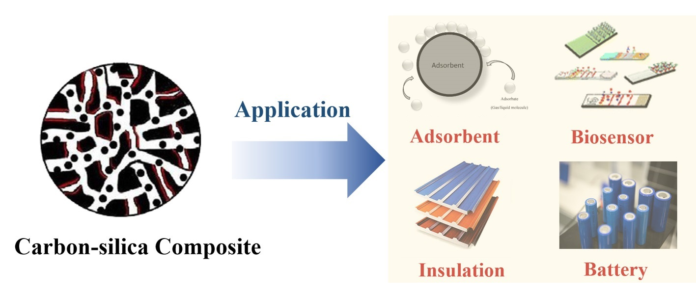
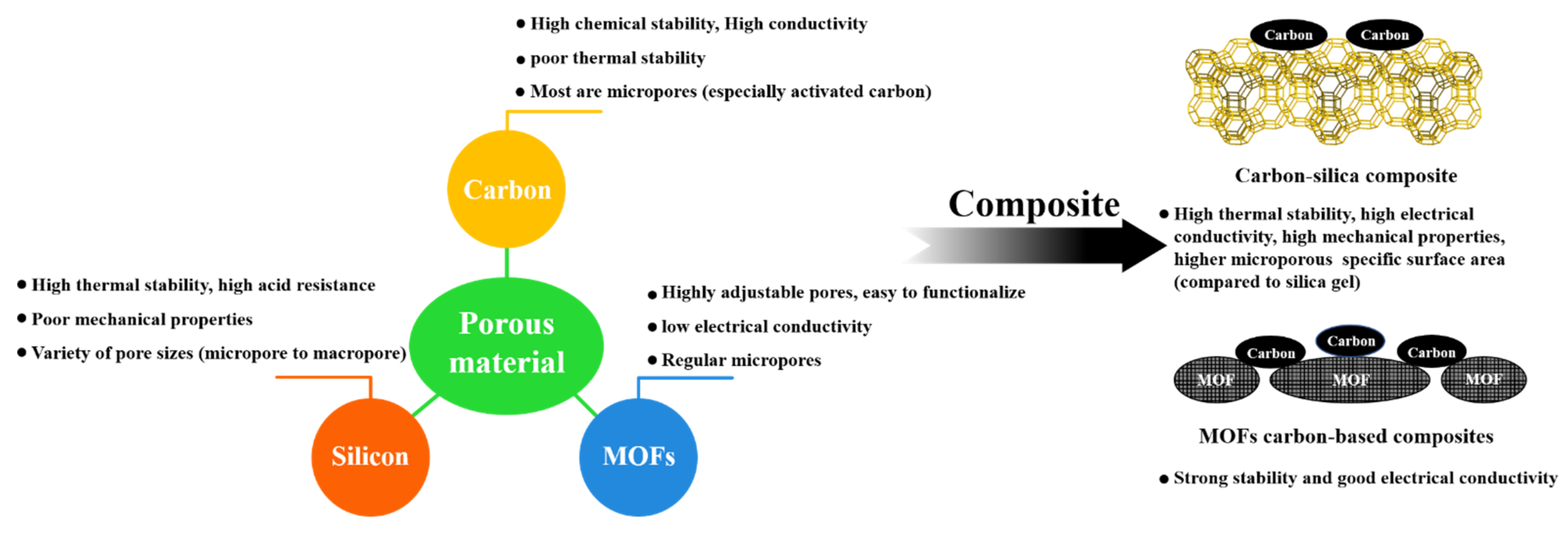
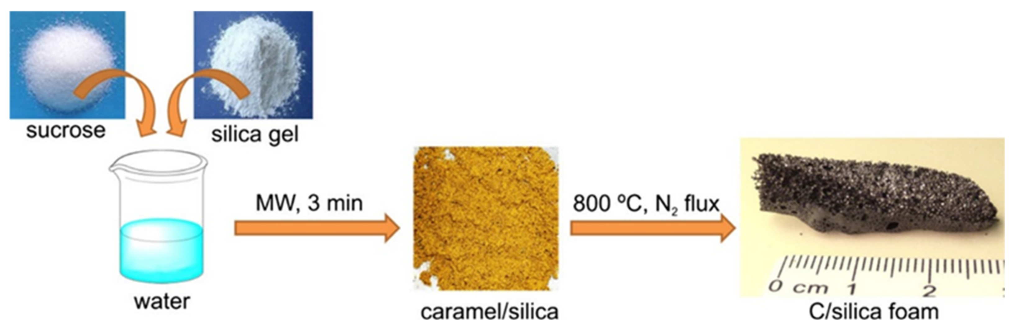
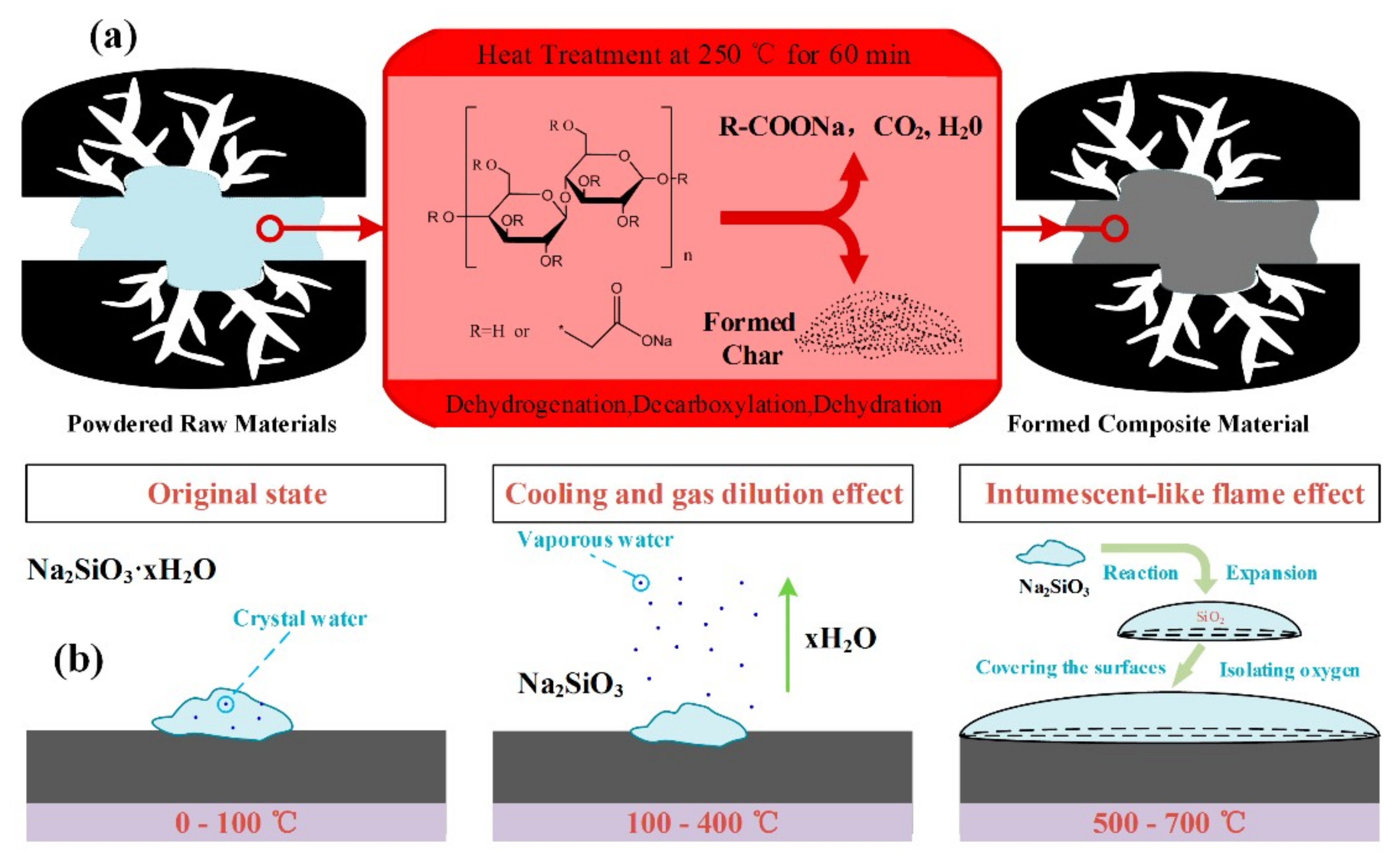
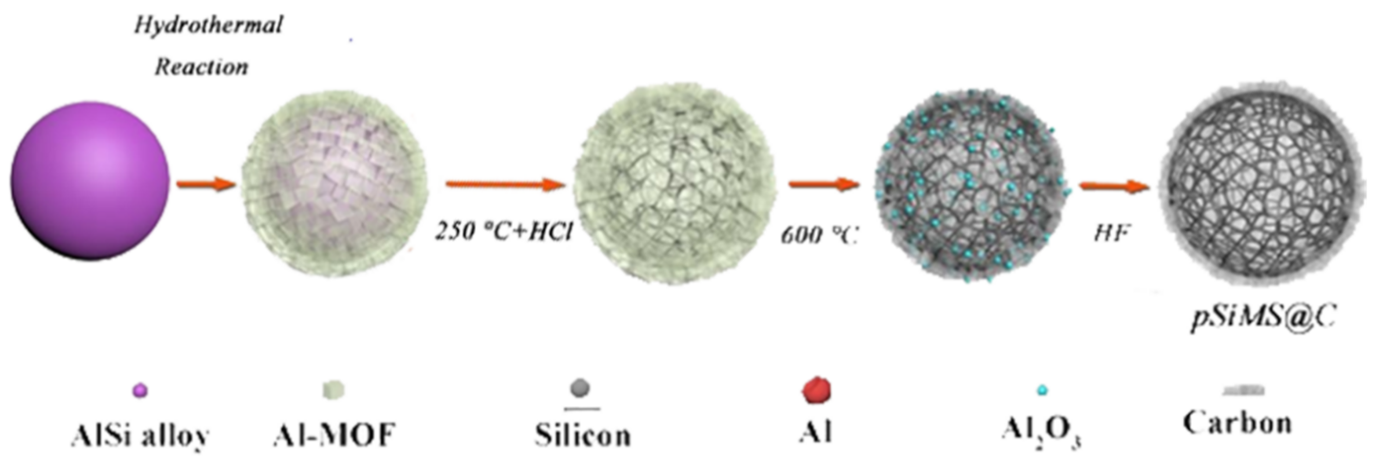
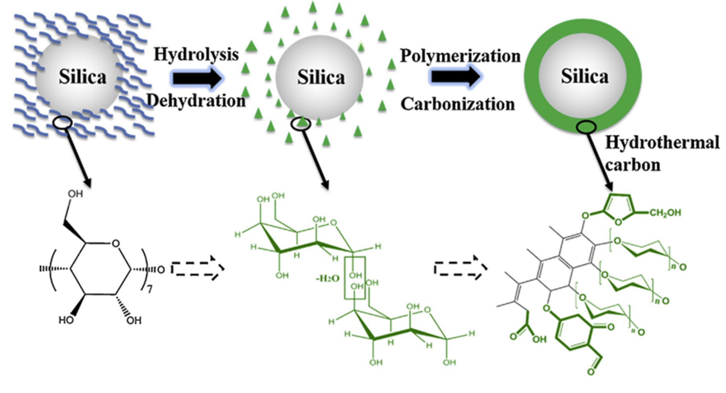
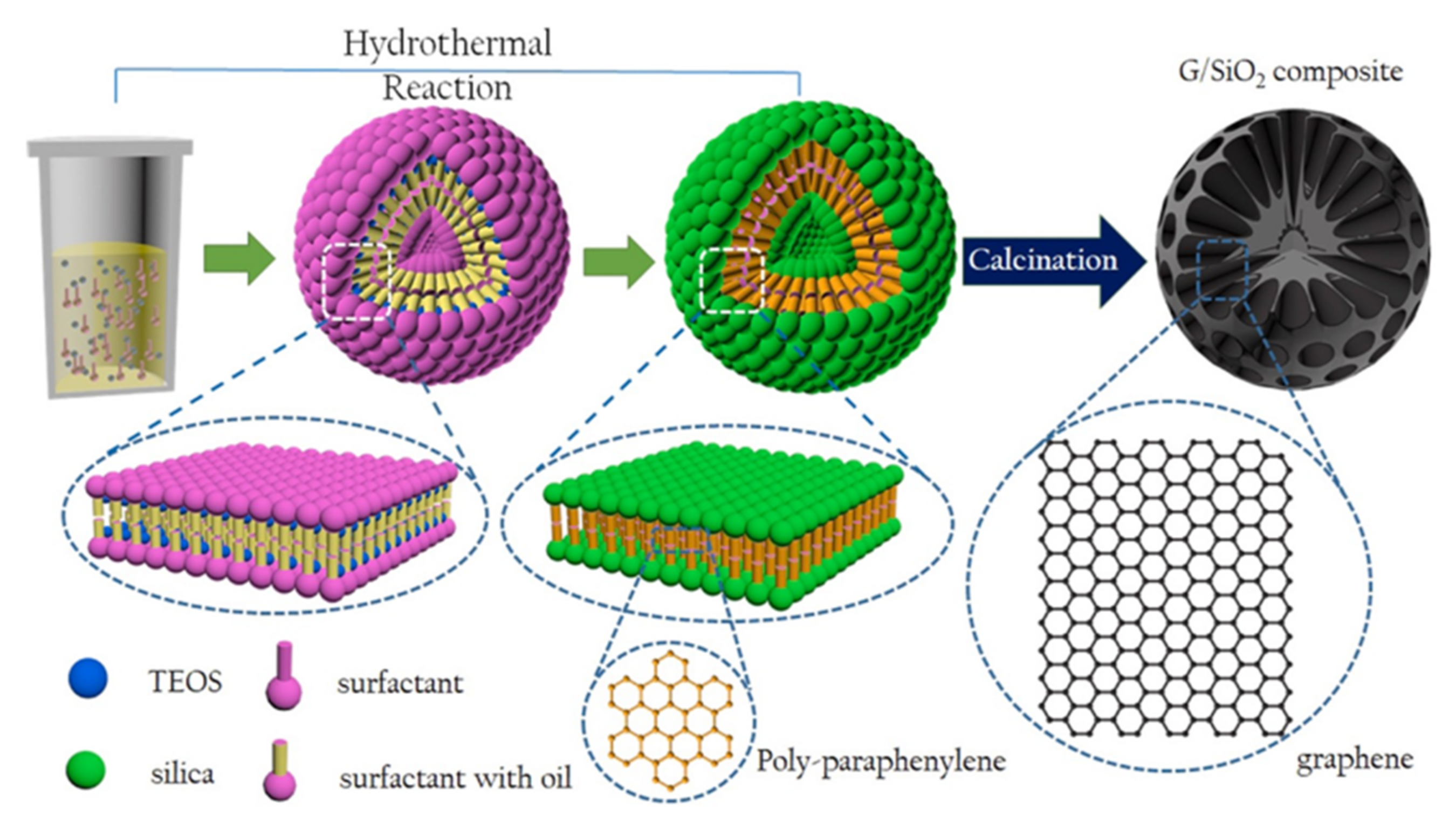
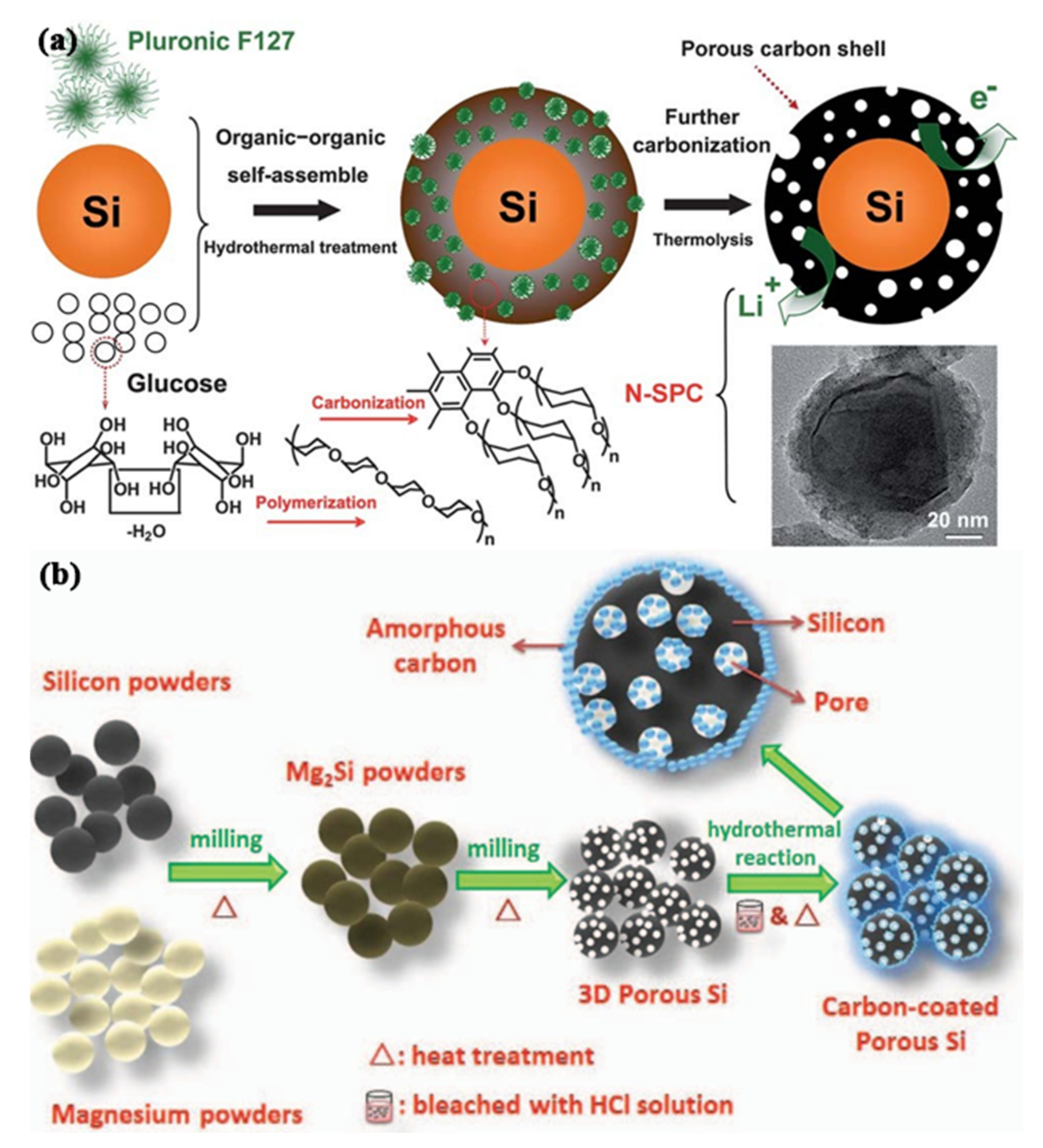
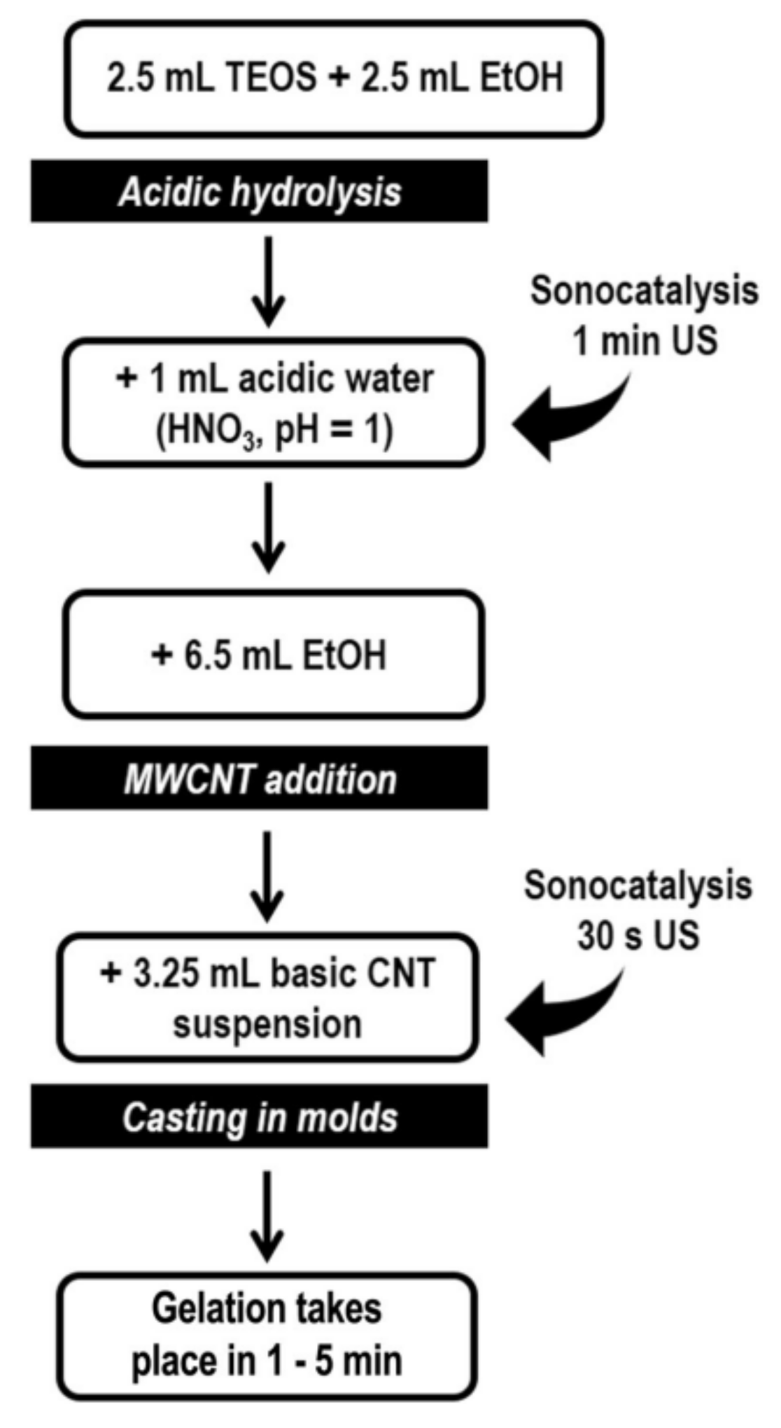
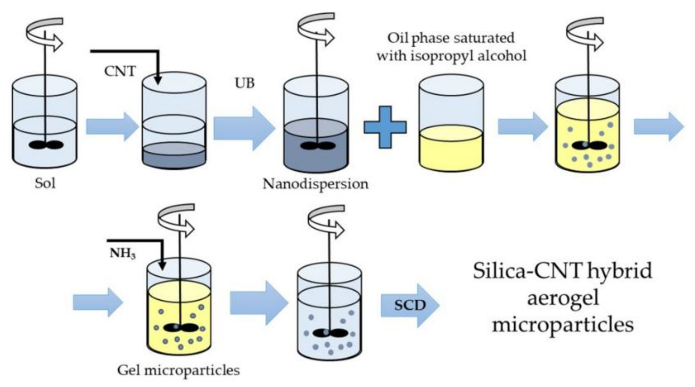
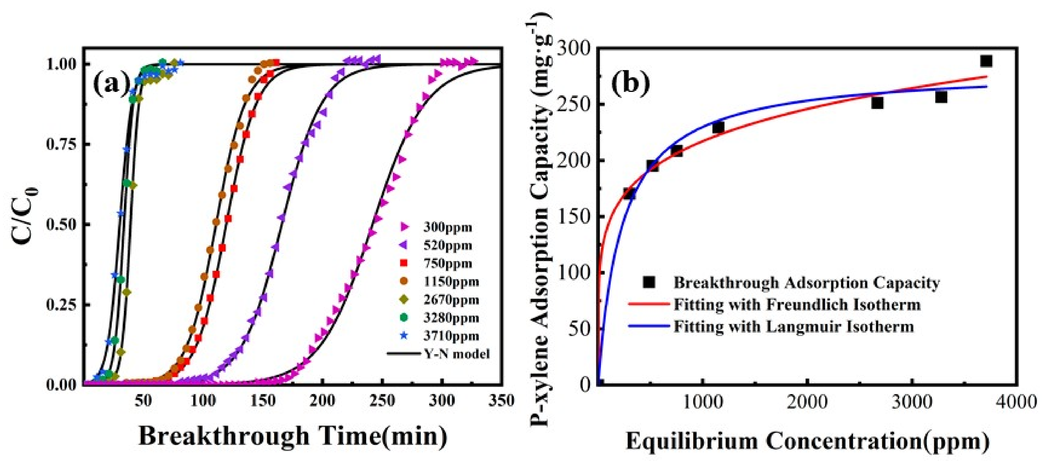
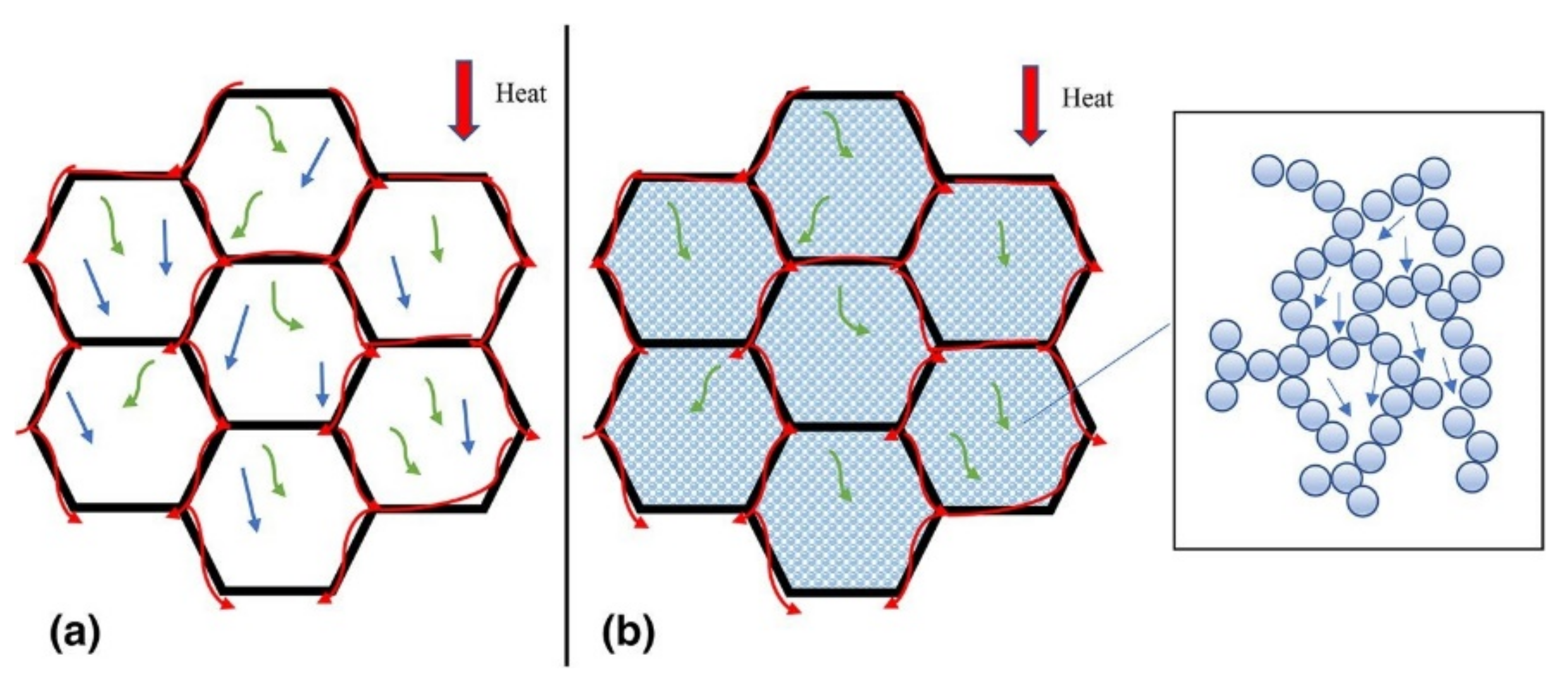
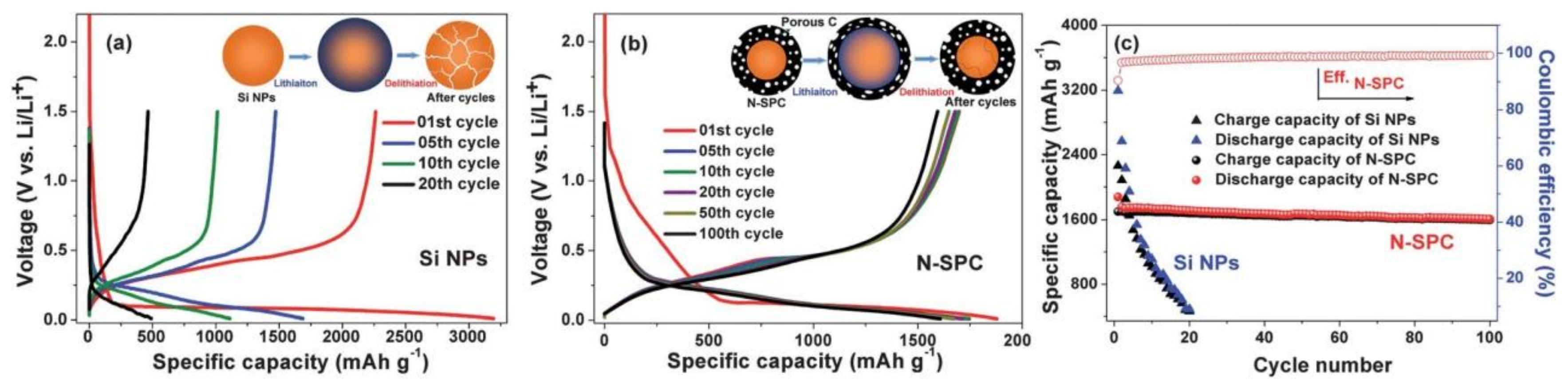
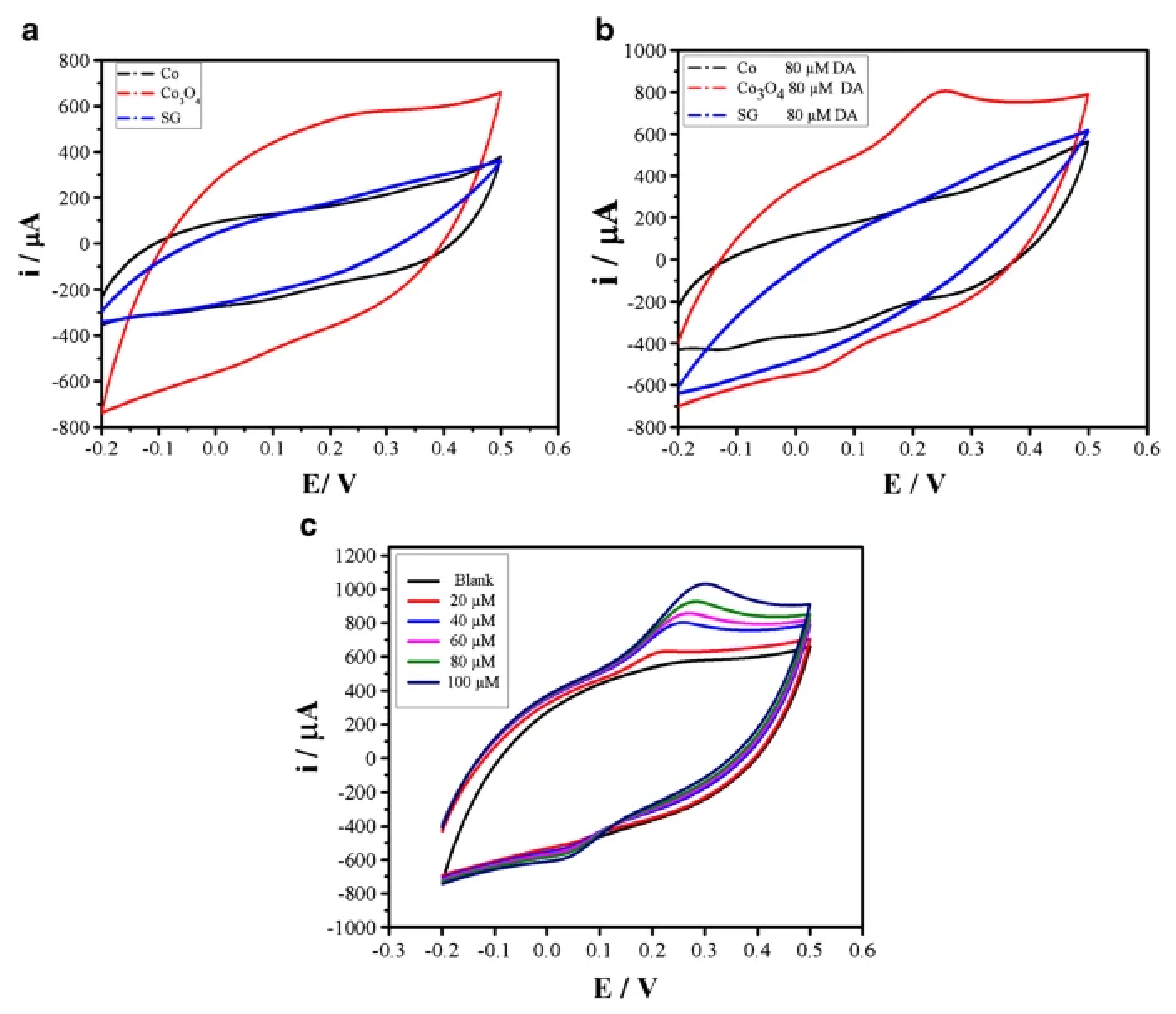
Table 1.
Advantages and disadvantages of carbon materials.
| Material | Advantages | Disadvantages | Refs. |
|---|---|---|---|
| Activated carbon | Wide range of precursors, high specific surface, low acid-base reactivity | Difficult to regenerate | [7,8,9] |
| Carbon nanotubes | High mechanical strength, excellent electrical and thermal performance | Difficult to disperse in aqueous and organic solvents | [10,11,12] |
| Graphene | Outstanding optical and mechanical properties | Difficult to disperse in aqueous and organic solvents, complicated synthesis | [13,14,15,16,17] |
Table 2.
Advantages and disadvantages of silica materials.
| Material | Advantages | Disadvantages | Refs. |
|---|---|---|---|
| Silica gel | Excellent mechanical properties, good adsorption capacity | Easily hydrolyzed in alkaline environments, poor adsorption selectivity | [32,33] |
| Mesoporous silica | Well-organized and controllable pores, easy functionalization, high thermal stability | Difficult to synthesize on a large scale | [34,35] |
| Molecular sieve | High specific surface, strong acidity | High energy consumption during desorption, high cost | [36,37] |
Table 3.
Representative reports on the preparation of carbon-silica composites by hybrid pyrolysis carbonization.
Table 3.
Representative reports on the preparation of carbon-silica composites by hybrid pyrolysis carbonization.
| Carbon Source | Silica Source | Pyrolysis Temperature (°C) | Pyrolysis Time (min) | Atmosphere | Benefits/Remarks | Ref. |
|---|---|---|---|---|---|---|
| Co(terephthalate) (2,2′-bipyridine) | Silica | 850 | 600 | Nitrogen | BJH surface area was 55.4 m2/g | [59] |
| Phenolic resin | Tetraethyl orthosilicate | 800 | 240 | Nitrogen | Uniformly ordered mesopores | [60] |
| Bio-oil | Amorphous silica gel | 800 | 10 | Nitrogen | BET surface area was 1056 m2/g, pore diameter was 4.8 nm | [61] |
Table 4.
Representative reports on the preparation of carbon-silica composites by hydrothermal carbonization.
Table 4.
Representative reports on the preparation of carbon-silica composites by hydrothermal carbonization.
| Carbon Source | Silica Source | Hydrothermal Temperature (°C) | Hydrothermal Time (min) | Benefits/Remarks | Ref. |
|---|---|---|---|---|---|
| Glucose, graphene oxide | Silicon-containing polyester | 160 | 360 | BET surface area was 12.7 m2/g, thermogravimetric temperature was 550 °C | [74] |
| Glucose | Silicon nanoparticles | 180 | 150 | Thermogravimetric temperature was 525 °C | [75] |
| Sucrose | Mesoporous spherical silica gel | 150 | 1200 | BET surface area was 416.0 m2/g, pore size was 6.64 nm, thermogravimetric temperature was 550 °C | [76] |
Table 5.
Representative reports on the preparation of carbon-silica composites by the sol-gel method.
Table 5.
Representative reports on the preparation of carbon-silica composites by the sol-gel method.
| Carbon Source | Silica Source | Catalyst for the Hydrolysis Reaction | Catalyst for the Polycondensation Reaction | Benefits/Remarks | Ref. |
|---|---|---|---|---|---|
| Multi-walled carbon nanotubes | Tetraethyl orthosilicate | Formic acid | Ethylenediamine | Thermogravimetric temperature was 500 °C | [88] |
| Activated carbon powder | Tetraethyl orthosilicate | Hydrochloric acid | Ammonia water | BET surface area was 725.0 m2/g, average pore size was 3.5 nm | [89] |
| Multi-walled carbon nanotubes | Tetraethyl orthosilicate | Nitric acid | Ammonium hydroxide | BET surface area was 650.0 m2/g, pore size was 17 nm | [90] |
Table 6.
Application of carbon-silica composites in the field of adsorption.
| Carbon Source | Silica Source | Adsorbate | Adsorption Capacity | Benefits/Remarks | Ref. |
|---|---|---|---|---|---|
| Multi-walled carbon nanotubes | Tetraethyl silicate | Toluene | 50.3 mg/g | BET surface area was 964.1 m2/g, micropore surface area was 465.3 m2/g, average pore diameter was 0.492 nm | [105] |
| Rice husk | NaX zeolite | CO2 | 79.6 mg/g | BET surface area was 980.8 m2/g, ultra-micropore volume was 0.181 cm3/g, 99% regeneration efficiency after 10 cycles | [106] |
| Paper mill sludge | Paper mill sludge | Iodine | 248.07 mg/g | BET surface area was 518.6 m2/g, micropore pore volume was 0.109 cm3/g, mean pore diameter was 5.7 nm | [107] |
Table 7.
Application of carbon-silica composite materials in the field of lithium-ion batteries.
| Carbon Source | Silica Source | Reversible Capacity after Cycling | Benefits/Remarks | Ref. |
|---|---|---|---|---|
| Citric acid and melamine | Nano-sized silicon powder | 1000 mAh/g after 300 cycles at 2 A/g | BET surface area was 107.0 m2/g, pore size was 4 nm | [113] |
| Multiwall carbon nanotube | Tetraethyl orthosilicate | 1150 mAh/g over 500 cycles | Average coulombic efficiency was up to 99.9% | [114] |
| Corn starch | Si nanoparticles | 1440 mAh/g over 500 cycles | Fast charge and discharge capability of 12 min | [115] |
Publisher’s Note: MDPI stays neutral with regard to jurisdictional claims in published maps and institutional affiliations. |
© 2022 by the authors. Licensee MDPI, Basel, Switzerland. This article is an open access article distributed under the terms and conditions of the Creative Commons Attribution (CC BY) license (https://creativecommons.org/licenses/by/4.0/).
Share and Cite
MDPI and ACS Style
Wu, T.; Ke, Q.; Lu, M.; Pan, P.; Zhou, Y.; Gu, Z.; Cui, G.; Lu, H. Recent Advances in Carbon-Silica Composites: Preparation, Properties, and Applications. Catalysts 2022, 12, 573. https://0-doi-org.brum.beds.ac.uk/10.3390/catal12050573
AMA Style
Wu T, Ke Q, Lu M, Pan P, Zhou Y, Gu Z, Cui G, Lu H. Recent Advances in Carbon-Silica Composites: Preparation, Properties, and Applications. Catalysts. 2022; 12(5):573. https://0-doi-org.brum.beds.ac.uk/10.3390/catal12050573
Chicago/Turabian StyleWu, Tianhao, Quanli Ke, Mei Lu, Pengyun Pan, Ying Zhou, Zhenyu Gu, Guokai Cui, and Hanfeng Lu. 2022. "Recent Advances in Carbon-Silica Composites: Preparation, Properties, and Applications" Catalysts 12, no. 5: 573. https://0-doi-org.brum.beds.ac.uk/10.3390/catal12050573
Note that from the first issue of 2016, this journal uses article numbers instead of page numbers. See further details here.