Review

Design Efficiency, Characteristics, and Utilization of Reinforced Foamed Concrete: A Review

1
Department of Civil Engineering, College of Engineering, Prince Sattam Bin Abdulaziz University, Alkharj 11942, Saudi Arabia
2
Department of Civil Engineering, Faculty of Engineering and IT, Amran University, Quhal 9677, Amran, Yemen
3
Department of Civil and Construction Engineering, Faculty of Engineering and Science, Curtin University, CDT250, Miri 98009, Sarawak, Malaysia
4
Higher School of Industrial, Civil and Road Construction, Peter the Great St. Petersburg Polytechnic University, St. Petersburg 195251, Russia
5
School of Engineering, Far Eastern Federal University, Vladivostok 690950, Russia
6
Construction Research Centre (CRC), Universiti Teknologi Malaysia, Johor Bahru 81310, Malaysia
7
Department of Civil Engineering, Faculty of Engineering, Universiti Malaysia Sarawak, Kota Samarahan 94300, Sarawak, Malaysia
8
School of Civil Engineering, SASTRA Deemed to be University, Thanjavur 613404, Tamil Nadu, India
*
Authors to whom correspondence should be addressed.
Submission received: 27 August 2020 / Revised: 23 September 2020 / Accepted: 30 September 2020 / Published: 17 October 2020
(This article belongs to the Special Issue Hierarchical Composite Materials)

Abstract

:
Foam concrete (FC) serves as an efficient construction material that combines well thermal insulation and structural properties. The studies of material characteristics, including the mechanical, physical, rheological, and functional properties of lightweight concrete, have been conducted rigorously. However, a lack of knowledge on the design efficiency of reinforced FC (RFC) was found in current research trends, compared to reinforced lightweight aggregate concrete. Therefore, this paper presents a review of the performance and adaption in structures for RFC. According to the code specifications, the feasibility investigation was preliminarily determined in structural use through the summary for the mechanical properties of FC of FC’s mechanical properties. For reinforced concrete design, a direct method of reduction factors is introduced to design lightweight aggregate concrete, which is also suggested to be adapted into a lightweight FC design. It was found that flexural shear behavior is a more complex theoretical analysis than flexure. However, a reduction factor of 0.75 was recommended for shear, torsion, and compression; meanwhile, 0.6 for flexural members. Serviceability limit states design should be applied, as the crack was found predominant in RFC design. The deflection controls were recommended as 0.7 by previous research. Research on RFC’s compression members, such as a column or load load-bearing wall, were rarely found. Thus, further study for validating a safe design of RFC applications in construction industries today is highly imperative.

1. Introduction

Foam concrete (FC) is a concrete composite with enclosed-air voids to reduce its self-weight. The light-weight characteristics are caused by introducing bubbles of air using suitable preformed foam into cement paste. The foam is formed using water solution, expanded foaming agent with pressurized air. The density of FC is varied from 300 to 1800 kg/m3 [1]. The presence of air bubbles in FC produces unique features compared with ordinary concrete, e.g., acoustic absorption, low self-weight, resistance to fire, thermal insulation, high porosity, high flowability, and required compressive strength [2,3]. FC is used effectively in various countries, such as Turkey, Thailand, Philippines, Germany, and UK [4]. FC is a lightweight construction material that highly depends on its density and constituents of mixture [1,3], and it can be used in various construction applications (Figure 1). The non-structural use of FC has been found actively in construction [5].
The cellular concrete is categorized into two types based on the pore-formation method: FC and air-entrained concrete [6]. In the method of air-entraining, chemicals, such as gas-forming, are mixed uniformly into the cement paste. As a result, the porous structure is formed by generating gas due to chemical reaction action while mixing [7]. The aerating agents, namely hydrogen peroxide, calcium carbide, and aluminum powder, are widely used. Two approaches are in everyday use to form the pores in FC; (i) the pre-foaming process, which includes the appropriate amount of preformed foam, is mixed with a water solution. (ii) Process of mixed foaming consisting of the cement and water is mixing to obtain the uniform paste; subsequently, the prepared foam is poured into the cement paste [8]. According to the curing method and its density [9], aerated concrete is categorized as autoclave (cured under temperature and pressure in a sealed device) and non-autoclaved concrete. For insulating and filling purposes, the density ranged from 300 to 600 kg/m3 is used extensively. The density varied between 600 and 1200 kg/m3, its application can be extended to non-load-bearing structures (soundproofing screeds, thermal insulation, partition wall, outer leaf building panel, and precast block). For the load-bearing structures, a high-density FC in the range of 1200–1900 kg/m3 is widely used [10,11,12,13,14].
Apart from providing good thermal [15,16], acoustic, insulation properties [15], and less depleting resource consumption with the replacement of industrial and agricultural waste as building materials [17,18,19], are the current research ventures towards low carbon footprint. Thereby, FC is also beneficial to the pre-fabrication industry by minimizing transportation frequency and machinery. FC is conventionally cast-in-situ, and its construction also brings the advantage of reducing temporary supports or props with smaller formwork pressures [7]. A higher strength-to-weight ratio can also be attained with the lightweight features, resulting in a smaller foundation, few columns, or longer beam span [3]. FC alternatively becomes one of the lightweight construction materials, as lightweight aggregate concrete competitively gives a narrow range of density reduction. In contrast, aerated concrete needs a high temperature at the curing stage to chemically induce the voids [12,20] (Figure 1).
The Romans first noted the significant improvement of workability in lime mortar mixtures. This improvement is observed by agitating animals’ blood to introduce bubbles in the lime mortar [1]. During 1923, the FC was placed in service for the first time as an insulative material [21]. In the 1950s and 1960s, FC’s production and its composition and physical properties were studied extensively first-ever. It is initially applied for ground stabilization and filling of void and afterward driven to more frequent usage as a material for building. For building performance, the consumed quantities of fossil fuels can be reduced for energy-efficient building by minimizing the amount of carbon dioxide emitted [22]. Reportedly, FC exhibited sufficient strength to meet the usage limits of material for construction and an industrial building [23]. No compaction and vibration are needed to fill the voids and cavities over a long-range. It offers excellent thermal insulation, good resistance to fire, freeze/thawing properties, and settlement-free and quick construction [24]. FC has found many applications in recent years; ground stabilization, maintenance of road sub-bases for bridge abutments, monolithic low-rise building, single dwelling building, thermal insulation, wall panels, and building blocks production, masonry grouting, cavity filling, well backfilling, double-pitched roofs, mono-pitched roofs, thermal protection of flat, acoustical barrier floors [25,26,27]. Although FC holds excellent properties as a suitable material for construction, its emergence was about 5.6, 33.3, 5.6, and 5.6% for countries like Africa, Europe, Australia, and North America, respectively.
Henceforth, it is to be noted that FC’s role in the building industry is not widely accepted due to a lack of knowledge, material sureness, and obtainability of required technology [28]. However, there is an occasional use of reinforced foam concrete (RFC) in the structural concrete system. This is due to a lack of knowledge on the fabrication of concrete structural applications. To this end, this paper reviews the design efficiency, characteristics, and utilization of RFC. It may have a different performance than ordinary concrete, with a relatively low tensile strength of FC. Material properties of FC were critically reviewed and the feasibility of structural use was also discussed according to the specifications of current codes of practice. For reinforced concrete design, the theoretical background for reinforced concrete was also studied and the adaption of codes of practice with reduction factors and the future direction of lightweight FC applications were also highlighted.

2. Factors Affecting the Characteristics of FC

Several factors affecting properties of FC, namely fresh and harden densities, aggregate grading, pozzolanic effect, foams used in concrete, etc. The following contents describe these factors.

2.1. Aggregate Grading

Table 1 shows the properties of FC for different aggregate grading. As claimed by [29], the finer of the aggregate size may increase FC’s strength. However, it is not practical to sieve the aggregate in massive production. As the particle size grading decreased, from passing through 2.36 mm sieve to 0.60 mm, and 0.10 mm sieve, the strength has an increasing trend [30]. In a massive casting, as mentioned in the slab casting research [31], it was found that the non-sieved sand may have lower strength as compared to those sieved samples. Therefore, for factory quality control, precast FC should be produced with graded sand; meanwhile, cast-in-situ concrete strength should be allowed for some reductions due to sieving is not practical at the site.

2.2. Rate of Pozzolanic Binders

From previous research [28,41,42,43], the cement replacements can be conducted with palm oil fuel ash (POFA), granulated blast-furnace slag (GGBS), pulverized fly ash and eggshells. The high content of pozzolanic binders shown in Table 2, may lead to C–S–H gel bonding the same as cement and therefore exhibit the good pozzolanic effect. It offers the excellent property of fire-resistant in FC [44]. To reduce the FC heat of hydration, fly ash, GGBS, and silica fume was utilized as a substitution for cement in the range of 10 to 75% [45]. It consumed additional time to reach the strength to the maximum extent. Its micro-filling effect had a significant contribution to the FC mix design consistency and long-term strength [46].
Stability is the term to describe the foams that exhibited in fresh and harden condition. Drying shrinkage occurs in most of FC where bubbles may burst during curing process. This can lead to increment of density. The difference may control within ±0.05 to prevent excessive shrinkage held in concrete matrix. Most of the summarized results in Table 2 achieved the 5% difference, and their strength were relatively valid for analysis. Furthermore, the strength is governed by its density. To conduct comparison, performance index is used, where strength in unit density. From previous studies, as shown in Table 2, pulverized fly ash and egg shell exhibited the highest and lowest of performance index respectively as compared to others pozzolanic materials.
Pozzolanic reactions, as shown in Equations (1) and (2), can be used for representing the activity where having SiO2 and Al2O3 for producing hydrated gels of C–S–H and C–A–H (Table 3) [47]. From previous research, it is recommended to limit their replacement cement with eggshells for 7.5% [42] and 20 to 30% for pulverized fly ash, PFA [41] and palm oil fuel ash, POFA [43] of cement replacements to maintain its strength from gradually strength decrement. Table 3 shows the constituents of pozzolanic materials.
Ca2+ + 2(OH) + SiO2 → C–S–H
Ca2+ + 2(OH) + Al2O3 → C–A–H

2.3. Foaming Agents

It was proved that the foaming agents do not affect the mechanical properties much where they do not affect the mechanical properties much where they alter the thermal properties and sorptivity of FC [51]. Chemical foam agents (Table 4) govern the density of concrete via the amount of air-voids formed in the mix of cement pastes. Foam air-voids are known as encircled bubbles created as a result of the adding of chemical foam agents. The foam agent content has a significant influence on concrete characteristics as its states; fresh and the hardened [52,53]. The quality of foam agent has great significance since it signified FC’s constancy and also influenced the strength and toughness of the produced FC [54]. The bubbles’ volume varies from 6% to 35% of the total final mixture in most FC applications [55]. Foam agents are inorganic and organic compounds in pellet or powder foam. The examples of organic agents are hydrazocarbonamide, azodicarbonamide benzenesulfonyl hydrazide, toluenesulfonyl hydrazide, azobisisobutyronitrile dinitroso pentamethylene tetramine, barium azodicarboxylate, and benzenesulfonyl hydrazide, while inorganic agents are sodium bicarbonate, ammonium carbonate, ammonium bicarbonate, and calcium azide [56].
Polyurethane foams are used as insulation spray for air-sealing buildings. Foam stabilizer is added to enhance its slurry viscosity, which consists of 20% of triethanolamine, 40% of polyacrylamide, and 40% of hydroxypropyl methyl cellulose [57].
However, Table 4 shows various commercial foam agents from E-markets. The chemical foam agents are ordinarily protein-based, saponin, resin soap, synthetic, hydrolyzed protein, detergents, and glue resins [58]. In the mixing stage of fresh concrete, the chemical a foaming agent usually added into with the base-mix constituents to produce air voids via chemical reactions of foam agent, as a void structure in the mass of concrete [45]. The utmost popular chemical foam agents are synthetic and protein-based. The protein-based foam agents formed in a higher grounded and enclosed-cell of air-voids structure. Permitting to incorporate the more prominent volume of bubble and gives a higher steady bubble network whereas the synthetic ones abdicate more prominent extension and hence lower density [58,59]. It is found that the extreme used of chemical foam volume causes a reduction in flow, strength and density of concrete [53]. Though that the flow of FC is considerably influenced by the time of mixing, showing that the lengthy mixing can result in the damage of the enclosed-cell of air-voids by plummeting the air content [60] (Figure 2).
Reportedly, FC’s strength is commonly affected by the volume of foam content instead of its dependence over the proportion of water and cement [62]. In particular, FC’s compressive strength is greatly influenced by the type, volume, and quality of the foaming agent. For instance, by synthetic-foam agent lower than protein-based foam agent [54,59]. It is found that the addition of air-voids in FC has less influence on elastic modulus than on hardened strength [58]. Overall, the chemical foam agent is recommended to be included directly after its manufacturing in a gluey form to assure the foam’s constancy. Constancy is commonly further attained by including foam steadying fluorinated surfactant into the FC [53,54,58]. Table 5 shows FC’s properties with a different dilution of foaming agent and Figure 2 shows the schematic diagram of the compressed-air foam generator [61].

2.4. Density

FC’s stability should be determined by the ratio between fresh and harden (testing age) densities to obtain a similar quantity of the applied voids by foams. The foams in fresh state may burst and the density at the testing age may increase subsequently. This phenomenon may alter the targeted density and increase the dead loads for the structural member’s design. The strength is dependent by harden densities and not related to fresh density. Fresh densities are measured to ensure the targeted density is achieved.
From Table 6, it can be found that finer aggregate size may stabilize the density of FC for quarry dust as sand replacements, while, charcoal as a sand replacement, exhibited high discrepancies on its fresh and harden densities. On the other hand, the additives like strength enhancement chemical may burst the foams as observed in [30]. Therefore, the chemical reactions between foams and additives must be identified before applying them to the FC mix design.

3. Characteristics of FC

FC is obtained from mixing base mix (normally mortar) with preformed foam (diluted foam agent with high pressure). Another type of cellular concrete is aerated concrete, which uses aluminum powder as a foaming medium at high temperatures. Aerated concrete will not be discussed, as the aluminum powder is a flammable chemical under almost all ambient temperatures and is unstable at elevated temperatures and pressures. FC’s material properties may have a significant influence on the structural performance of these lightweight structures. The mechanical properties have been summarized, which give a significant and positive response to their structural behavior. The functional properties will be discussed, and these might not influence an FC building’s overall structural performance but notably benefit in reducing carbon footprint in building operation. FC consists of cement as binders, sand as aggregates, water, and foams. As a consideration of economic and performance enhancements, many researchers were introducing additives or replacements to the FC, such as fly ash [43,46,58,77], silica fume [58,77], superplasticizer [77], fibers, and others. There is no specific method to determine the mixing proportions. However, Kearley [46] proposed the calculation of mixing the proportions by the target density method, and other researchers have practiced this.

3.1. Fresh Characteristics

Fresh characteristics may affect hardened mechanical characteristics. As an instant, self-compacting characteristic must be obtained in a fresh state to maintain its workability, where foams bursting may occur during concrete compaction and needs to avoid this event in concrete casting. Figure 3 shows the test procedures for flow table and inverted slump according to ASTM C1437 [78] and ASTM 1611 [79,80]. There are stability calculations and workability test in this stage. The consistency and rheology should be attained as the mixed slurry can flow and hold the bubbles without segregation. The accepted workability should fulfil spread-ability between 40 to 60% of the 20s for a self-compacted mix [1,69] using an inverted slump test setup. Several methods to obtain a mix’s stability based on the variance between the attained plastic density and anticipated plastic density, which is not meant to exceed 2 to 7% [1,81,82]. Moreover, the workability of base mix for FC can be accepted when achieving a spread of 85 to 125 mm for the mortar mix and 115 to 140 mm for the mix with fly ash [83,84].
Other than workability slump test, the base mix also can be determined from flow table test. From Figure 4, for base mix flow table test, it was recommended to have water-cement ratio of 0.3 to 0.36 in order to obtain the flowability with optimum performance index, where flow diameter of 25 mm may cause segregation when mixing with stable foams [80]. The particle size of binder and aggregate also affect the concrete flowability but higher water needed as the surface area increase for inter particle lubrication. Due to different methods have been assessed for FC workability, comparison was barely made. However, it is suggested to have flowable concrete to avoid mechanical compaction that potentially bursts the pre-formed foams in concrete matrix.

3.1.1. Consistency

The FC property assessment at a fresh state regarding stability and consistency is measured through the flow cone and marsh cone test. FC’s consistency is considered acceptable when the value of flow time is less than the 20 s, and flow values range from 40 to 60% [69]. A study finding revealed that the base mix consistency was dropped considerably with the foam addition. This phenomenon is attributed to decreased dead weight, greater cohesion, and a higher dosage of superplasticizer [9]. Despite the FC consistency had a trend towards increasing at a higher ratio of water to cement, the surplus quantity of water led to segregation. Anand [85] studied the characteristics at the fresh state of FC comprising GGBS as a small substitution of cement and fly ash as substitution of fine aggregate. No considerable change in the workability of FC was observed with ultrafine GGBS addition. Furthermore, the decreased consistency was observed with the fly ash addition resulting from higher particle fineness and higher water demand. More general note, the factor that affects the mix consistency is aggregate density. The consistency is reduced, resulting from low-density aggregate, and it can be enhanced by the fly ash addition [1].

3.1.2. Stability

It is pointed out that adding foam in the base mix had a significant impact on mix stability. The FC is considered as good and stable when its spread flow is 45% [86]. The ratio of water to solid is essential to generate a higher stable mixture with fly ash. The ratio of water/cement is significantly reduced lower than 0.3, with the inclusion of water-reducing admixture, resulting in a 43% improvement of stability. A small amount of foaming agent positively influences the stability of FC [87]. The cohesive strength between the bubbles and base mix particles led to an increase in the mix stiffness; the collapse of air foam occurs when mixing, which affects mix stability. This phenomenon was avoided with an increased ratio of water to solid [69]. Several investigators suggested various techniques for finding the mix stability, such as (i) the FC density at the fresh stage and target density compared to each other, (ii) the ratio of actual and calculated water to cement was compared and maintained near 2%. Jones et al. [86] examined the properties of FC stability, and the research outcome revealed that the lower densities (<500 kg/m3) were observed, resulting in a higher risk of instability. The Portland cement mixes with stable lower density were prepared by adding compatible calcium sulfoaluminate (CSA) cement as a partial substitution. Cong and Bing [88] stated that strength and thermal insulation properties could be enhanced by incorporating silica fumes that provide pores more closely aligned and closed. Findings indicated that the FC incorporated with quicklime led to a substantial increase in density and strength, but foam’s stability is degraded. Extensive experimental research was conducted by utilizing the materials locally available [89]. Foaming agent was prepared with saponin in plants, and binding material is produced with lime and gypsum [9].

3.1.3. Workability

The FC workability can be assessed through the visual examination of viscosity. The slump test is commonly used and unsuitable for FC with lower density [1]. It was highly recommended to find the workability of lightweight concrete by the spreadability method [90]. An open-ended cylinder with a 150 mm height and a 75 mm diameter was utilized to measure spreadability. The cylinder is raised, and the mean of two diameters of the spread volume was calculated bidirectionally; the measured diameter should be close to 5 mm. FC’s spreadability falls in the range of 85 to 125 mm in cement sand mixes, and 115 to 140 mm in fly ash mixes. When the volume of foam is higher, the mixes turn into stiffer and needs a more significant amount of water to maintain workability. It was also mentioned that quarry dust mixes displayed higher workability at a lower ratio of water to solid than bottom ash [91].

3.2. Mechanical Characteristics

An assumption has been made that the FC had passed the requirements of fresh characteristics before investigating its mechanical properties in the hardened stage. From equilibrium equations of the basic principles, the stress–strain of steel and concrete at both elastic and plastic regions and the yield strengths of steel and concrete, are essential parameters in reinforced concrete design. As steel, is a quality-controlled product from factories, it will be less focused. Research findings for concrete compressive strength (yield strength), modulus of elasticity, tensile strength, and FC’s flexural strength are summarized. Moreover, Figure 5 shows hardened FC with air bubbles distributed in the concrete matrix.

3.2.1. Compressive Strength

The density of FC is one of the underlying determinants to decide its compressive strength and depends on dry density, porosity, and age [1]. The strength of FC is derived from the concrete matrix and its microstructure. The compressive strength decreases exponentially when the concrete’s density decreases, relative to normal concrete [1]. The observation was made that the FC blocks density is much less than conventional concrete, and burnt clay bricks resulted in lightweight structure [93,94]. The seven days compressive strength was 1, and 10 MPa with the corresponding dry densities were 400 and 1200 kg/m3 [3]. The ratio of water to cement, size distribution, spacing factor, the shape of air void, filler type, curing, and foaming agent type utilized are other factors influencing the compressive strength. Additionally, exceptional compressive strength was attained, resulting from the mix contains fine sand with the pores distributed uniformly than the course sand of uneven pores [95]. The strength is also more reliant on the cementing matrix for compressive strengths up to approximately 35 MPa. Research has proved that FC can achieve a high strength of 39.5 MPa for a density range of 1000 to 1500 kg/m3 with concrete age of 365 days [96]. The mixture contained rapid hardening Portland cement and graded ash (ash/cement = 1, water/cement = 0.6, and water/binder = 0.3) with 1500 kg/m3 of targeted density, resulting of 43.3% porosity in 365 days, dry and saturated densities of 1287.3 and 1530.5 kg/m3, respectively.
It was pointed out that the FC comprised various aggregate types such as expanded shale, waste paper sludge ash (WPSA), glassy, quarry dust and clay, and lightweight porous exhibited exceptional compressive strength [97,98]. An earlier study indicated that the specimen contains with and without pulverized bone. No significant difference was spotted in tensile and compressive strength and workability, while the design density is 1600 kg/m3 [99]. The compressive strength of FC is alleviated by the inclusion of lightweight porous aggregate [100]. Other findings revealed that FC had an increasing trend of strength by altering the ratio of water to cement and alleviating large-sized bubbles [101]. A higher-strength of FC is attained when the ratio of water to binder is differed in the range between 0.17 and 0.19 [1].
FC’s compressive strength is enhanced by adding fibers resulting in inhibiting the micro-crack through adequate fiber bridging action. The significant enhancement in strength was noted in FC due to the various types of fiber addition; carbon, polyamide, glass, polyvinyl alcohol, polypropylene, and polyolefin [74,102]. The addition of steel fibers increases FC’s weight, and it also displays a tendency to settle; thus, it is not recommended for this type of concrete [103]. As reported by Steshenko et al. [7], the size of voids in the FC mixture is alleviated by introducing the microfibers and plasticizer. Additionally, modifying additives inclusion resulted in a large amount of closed pores formation in FC. Reportedly, the FC strength had a decreasing trend with increasing content of both foam and fly ash [97]. From the test and research on lightweight concrete, it is observed that the FC contains fly ash exhibited 36% enhancement in compressive strength in comparison to the bricks made with clay [9]. In general, it is found that the volume and type of foam agent and cement type are highly influenced by FC’s strength.
Table 7 shows the empirical formulations for obtaining FC’s compressive strength that might be used to the concrete members’ structural performance design. The majority of the equations are associated with the influence of the casted concrete’s gel-space ratio. The effect of the gel-space ratio has been examined with uniaxial and biaxial compressive failures [104] for concrete pastes and mortars. The micromechanics theory has been applied, and proven that the clinker-induced strengthening effect increases as the initial water-to-cement ratio and hydration degree decrease. Prediction of FC strength at the microstructural state is well-investigated with the development of series equations from Table 7, and they have been applied to the compressive strength prediction of FC. For more precise prediction, microstructure or nanostructure level should be studied as there are pores scattered in the mortar matrix. Unlike previous research [104], the pores are developed during the hydration process while pores in FC are introduced to mortar before the hydration process. Therefore, detailed investigation should be conducted to include FC characteristics.

3.2.2. Modulus of Elasticity

The modulus of elasticity of FC is 25% smaller than normal concrete, and it varies from 1 to 12 kN/m2 with the corresponding dry density ranged between 500 and 1600 kg/m3, respectively [107]. It is showed that the value of elastic modulus in FC is depended upon the aggregate fineness. FC exhibited a lower elastic modulus value when fly ash is used as fine aggregate than the sand. This phenomenon is ascribed due to a large fine aggregate quantity in the sand mix [81]. The FC comprising a huge volume of coarse aggregate was exhibited lower elastic modulus value. The FC’s elastic modulus value is significantly increased by incorporating the 0.5% dosage of polypropylene fibers [2,101,107]. It has been reported that the modulus of elastic for FC is four times lower than normal concrete [108]. Higher content of fine aggregate improved the FC modulus of elastic [107,109,110]. Table 8 shows the examples of empirical models for the elastic modulus for FC. Low elastic modulus provides more flexible structures towards deformation, which will induce large deflection at the ultimate limit state and corresponding high cracks at the serviceability limit state, preferable in seismic areas [101]. Serviceability limit state checking on deflection is essentially needed. This large deformation may exceed allowable deflection for safety perception, which will make the concrete fail at the early stage of loading with this deflection limitation. On the other hand, it was found that FC’s stiffness has been reduced after 90 °C for an investigation of FC in elevated temperatures [111].

3.2.3. Splitting Tensile, and Flexural Strengths and Fracture

The flexural strength of the lightweight aggregate and standard concrete is superior to FC. It became known that the ratio of flexural and compressive strength in FC falls between 0.2 and 0.4 is more significant in comparison with standard concrete, which had a ratio ranged between 0.08 and 0.11 [63]. It is also reported that the ratio between splitting tensile and compressive strengths ranged from 0.2 to 0.4, which was greater than ordinary concrete has a ratio of 0.08 to 0.11 [11]. As pores formed in the concrete matrix, it may create non-load cracks, which gradually reduces FC’s splitting tensile strength. The American Concrete Institute [113] suggested adding fibers to benefit the splitting tensile strength at an early age. Initial cracks of concrete may become a permeable element that accelerates the corrosion rate of the reinforcement bars. By adding fibers, they may increase FC’s tensile strength by reducing cracks initially at the serviceability limit state. The flexural strength was determined for FC with fibers, namely polyolefin [74], polypropylene [58,114] and waste tire steel fibers [55], which added into the base mixture before foams are added. These fibers only marginally increased the flexural strength of FC. Moreover, pulverized bone has been replaced for cement in FC mixes, and its flexural performance has been studied [108]. The cracking formation and propagation did not affect, while there was an accumulative effect in the pulverized bone. However, increasing the replacement was significant in reducing the bending resistance of the tested beams [108].
Although many researchers were trying to relate the splitting strength to compression strength. The splitting strength of a given lightweight concrete may not upsurge in a trend similar to the increment of compression strength [115], where the tensile strengths are being over-estimated as the compression strength increases above 35 MPa. Conferring to ASTM C330 [116], the lowest of 2.0 MPa for tensile splitting strength is required to ensure the material performance adequacy. Previous research findings [114] showed FC’s ability to achieve 2 MPa of splitting tensile strength on 90 days of concrete age with polypropylene fibers.
Fracture energy is the energy dissipated that is supplied to a growing crack tip and balanced by the energy dissipated from new surfaces’ formation. FC beams’ fracture energy was identified with three-point bending tests on jagged beam samples [117,118]. The fracture strength increased in relation to the increments of compressive strength and density. This fracture strength also affects the bond strength between the reinforcement bar and concrete.
The ratio between the flexural and compressive strength varied from 0.15 to 0.35 is stated by Narayanan and Ramamurthy [119]. This ratio was close to zero in FC’s case, with the corresponding density being under 300 kg/m3. The addition of appropriate fibers in FC with a higher modulus of elasticity, adequate length, and size can reduce cracking at the earliest age. The fiber addition in FC tended to change failure mode from brittle to ductile, which led to the excellent enhancement in flexural strength [58,120]. Investigators reported that the exceptional flexural strength could be achieved in natural foaming agents, which are most readily available compared to synthetic foaming agents [39]. For an equivalent density of FC mixtures without lightweight aggregate, fly ash, silica fume, and water-reducing admixture, it led to enhancement in ductility as compared with FC incorporated by additives on the mechanism of failure. It is worth pointing out that the additive based FC exhibited higher width of cracks in lateral failure earlier the damage, and the increased decisive stress was noted with increased density [120]. Due to less reinforcement and low shear strength in FC resulted in untimely deformation. The utilization of carbon and expanded polypropylene fibers made a positive contribution to improving foam’s behavior under shear [121]. Another contributory factor affecting FC’s flexural strength is the amount of water, while the water amount is exceeding causes a deficiency in flexural strength (uniform binder content) [91]. Besides, the splitting strength is greatly affected by the inclusion of fibers in FC. It was reported that a 2% dosage of short polymer fiber, and the grid reinforcement (glass-type bi-directional) have significantly improved flexural strength [2,101]. It was also stated that the fiber amount is excessive of 5%, the strength and interaction between two reinforcement were reduced drastically [122]. The more excellent enhancement in FC’s mean failure load can be achieved when carbon and basalt grids are effectively used as reinforcement [123].

3.2.4. Time Dependency

The time dependency properties of FC include the drying shrinkage and creep strain. Drying shrinkage initiates in the first 20 days of concreting time, which significantly affects the concrete strength. The drying shrinkage for FC was found to be around 4–10 times greater than ordinary concrete. It has been suggested that reducing the adding of water to the cement ratio [1] can solve the drying shrinkage problem. The lightweight sand aggregate and fiber are also added to control the potential cracking risk [124]. Nevertheless, fly ash can diminish the drying shrinkage of polyurethane FC [125]. In terms of creep, sand was found more effective than lightweight aggregate in minimizing it for FC [40]. All prediction models, GL2000 [126], ACI 209 [127], SAK [128], and CEB MC90 [129], failed to estimate the drying shrinkage and specific creep of FC without aggregate [124].

3.2.5. Thermal Performance

FC is well-known for its use in acoustic and thermal insulation. FC has a 10-times greater level to absorbs sound in comparison with normal concrete [130]. Furthermore, FC’s relatively low thermal conductivity has become a feature for thermal-insulated walls, which may reduce the electricity consumption of ventilation, heating, and air conditioning systems. These functional properties do not contribute to FC’s structural behavior but an added token in low electricity consumption for building performance.
The thermal properties of FC have been simulated for a range of 300 to 1700 kg/m3 [131]. The two dimensional (2D) numerical model can be used for the porosity of less than 35%. The finite volume method was adopted for heat transfer equations [132]. Moreover, an analytical solution was developed in porosity and pore size for FC with density varied between 600 and 1800 kg/m3. The results have been validated by experimental investigation.
Geopolymer FC has a relatively low thermal conductivity, ranging from 0.15 to 0.48 W/mK for densities between 720 to 1600 kg/m3 [133]. Geopolymer FC with oil palm shell has found 48% lower the thermal conductivity than conventional brick while obtaining 54% higher strength than normal weight concrete [134]. Research [51] found that type of foaming agent may affect the thermal properties and sorptivity of FC. It is less sensitive to alter in air content by protein to synthetic foams for concrete thermal conductivity. Previous research found that the thermal properties depend on the quantity of air trapped in concrete and the size of the foams. During building operations, the FC application may reduce the energy used.

3.2.6. Acoustic Characteristic

The law of mass controls the transmission loss (TL) of airborne noise over FC. TL indicates frequency and density, and it depends on internal resistance and the wall rigidity [135]. The normal concrete has comparatively low acoustical absorbance than FC [133]. Acoustical absorbance investigation on geopolymer based FC (GFC) revealed that the absorptivity for lower frequency sound waves varied between 40 and 150 Hz was much higher and more critical to the thickness of material [133]. No significant changes in acoustical absorbance at low-frequency waves. On the other hand, fly ash addition resulted in higher acoustical absorbance at higher frequency sound waves in the range of 800 to 1600 Hz. The dosage of foam is increased from 5 to 10% caused a decrease in material effectiveness for a low-frequency sound wave. It also improves the materials’ effectiveness for average frequency sound waves between 600 and 1000 Hz [9]. The GFC with 20 to 25 mm thickness showed an acoustical absorbance rate of 40 to 150 Hz. It also indicated that the foamed cellular concrete with the density ranged between 400 and 700 kg/m3, with the corresponding coefficient of absorbance ranged between 0.20 and 0.30 [9]. The sound propagation is obstructed by the closed disconnected pore, which leads to reduced absorption, although it has relatively high porosity [1,3].

4. Reinforcement System

Since the foamed concrete is taking the compression stresses, reinforcements are introduced in the structural members with poor tension behavior. Reinforcements can be applied within concrete matrix, usually called fiber-reinforced concrete (will not discuss further in this manuscript), whereas, they can also apply to a structural member as a tension system in concrete, recognized as reinforced concrete, those referring to bar reinforced concrete. This composite system has been applied to building systems in their extensive history as it works excellently with the building loads within building servicing periods.

4.1. Bar Reinforcement

The tension bar is usually used in the concrete structures, typically steel bar, in taking the tension or flexural or shear stresses of a building. The tension bar has shown a good characteristic with compressible concrete, to form a composite structure to sustain all applied loads. Like normal concrete, FC also requires these bars (or tension system) to form a reliable structural member. Steel reinforcement bars are fabricated according to code specifications. The referred codes include ASTM (A706 [136] and A615 [137]), Eurocode (EN10080 [138]), British Standard (BS4449 [139] and BS6744 [140]), Australian codes (AS4671 [141]). All of these bars must meet the fabrication requirements before applying them into FC design. Fiber-reinforced polymer (FRP bar) also has been innovatively used in RFC design. However, there is no sufficient data in FRP-reinforced FC design and it is suggested to use empirical experimental data to perform analysis for such combination.

4.2. Frame Reinforcement

Other than tension bars, the steel frame also has been introduced in the RFC design, notably slab member [142] where light steel frame was inserted into the FC slab for flexural tests. The steel frame was served as resistance to tension and shear stresses of the designed FC slab. No referred code has been introduced, but the structural behavior has been analyzed using the stress block method. Figure 6 illustrates the steel frame reinforcement in FC slab.

5. Reinforced Foamed Concrete (RFC)

Before applying into the reinforced FC system, some requirements that need to be achieved for the FC properties. The structural use of concrete should satisfy the minimum concrete grade of C20, according to the Buildings Department of Hong Kong [143], which is a minimum value of 20 MPa at a 28-day concrete age. Minimum grades from BS 8110 [144] for reinforced concrete are C15 for lightweight aggregate concrete and C25 for normal weight concrete. As Eurocode 2 [145] does not specify the minimum compressive strength, each density class’s minimum requirement should be fulfilled for good design and building condition. Moreover, ACI 318-14 Section 19 [146] specifies that the structural use of normal or lightweight concrete would satisfy a minimum strength of 17 MPa for a 28-day concrete age. For different moment frames and structural walls, the recommended minimum and maximum compressive strengths are 21 and 35 MPa, respectively. Therefore, the FC’s ability, mentioned above, has a compressive strength requirement that makes it successful for the first screening process. ASTM C330 [116] provides the lowest tensile strength of 2 MPa and FC is able to achieve this tensile strength with polypropylene fibers.
For durability, it is not essential for the concrete to be incredibly durable, since covers can be applied to resist the potential environmental hazards and chemical attacks. As the pores are not continuous in FC, it gives an advantage to the durability as the hazards may not penetrate into reinforcement bars to reduce its serviceability duration. However, Eurocode 2 and ACI 318 categorize the concrete into several categories for potential threats, such as sulfate attack, chloride exposure, etc. It was proven by [147] with SEM images of the formation of 50–100 μm pores and the maximum dosage of liberated foams was 0.6% by weight of the binder. When exceeding 0.6%, the pores’ size was increased thanks to the formation of interconnected pores.
Shrinkage and creep are other variables in structural concrete design. As there is a lack of information for shrinkage and creep, theoretical models, such as Pickett’s and Hansen’s equations, have failed to calculate FC’s reliable predictions [124]. Lightweight aggregate, sand, and fibers make up the mixture of materials that potentially improve these effects. Therefore, a new prediction model should be developed for structural concrete design. At this stage, shrinkage and creep behavior has been identified, where they have more significant effects than normal weight concrete. A prediction model is yet to be developed.
Therefore, after all these related properties have been investigated and prediction models have been developed, FC can be applied to a reinforced concrete structure design. Although there are no mandatory requirements, like creep and shrinkage, it is advisable to include reinforced foamed concrete design. It has more significant effects than normal weight concrete, and has a closed correlation with concrete elastic modulus, tensile strength, and flexural capacity.
There are four identified basic actions for reinforced concrete structures: bending, axial load, shear, and torsion. These actions can be designed solely or in any combination to fulfill Navier’s three principles: stress equilibrium, strain compatibility, and material constitutive law. Metal reinforcement has been introduced to the concrete to take the applied splitting strength where concrete is weak at the tension zone. The stresses redistribution of reinforced concrete elements due to the problem of strain compatibility between reinforcement steel and concrete may induce excessive deflections and lower the member’s structural performance [148]. Therefore, bond strength is one of the reinforced design concrete parameters due to the strain compatibility problem.

5.1. Bond Characteristics

Several factors influence the bond characteristics between concrete and steel bars, namely aggregate size, water–binder ratio, type of reinforcement bar, bond length, bar diameter, and confinement. Pull-out tests are usually used to determine the bond strength and bond stress-slip relationship. Previous related research data have been summarized in Table 8. Research of [148] discovered that bond strength for lightweight concrete was twice the code equation prediction than experimentally. Generally, FC has a lower bond strength compared to normal weight concrete. Researchers from Stellenbosch University [102,149,150,151] found that material improvement can be done by the addition of aggregate to improve cracking tortuosity. The additive of polypropylene fibers improves the bond between FC and reinforcement bar, and increment of fracture energy, material brittleness, and reinforcement bond (Table 9) [102,151]. Durability has been reported in [102] and more complete results will be reported in the future. Figure 7 shows the failure modes of FC with steel strips that obtained from previous investigations [152,153,154].

5.2. Previous Research on RFC

Several research has been conducted for reinforced foamed concrete members and summarized in the following contents.

5.2.1. Steel and FRP RFC

Jones and McCarthy [109] were preliminarily studying the possibility of applying FC to flexural beams with gradual decreases in density. It has been concluded that the characteristics of FC, including stiffness performance, comparatively low tensile strength, and excellent drying shrinkage strain, ref [109] may result in different structural behaviors than normal weight concrete. The previous investigation on the FC beam reinforced by wire mesh as reinforcements achieved greater flexural and compressive strengths than those FC with no reinforcement or reinforced by plastic mesh [162]. For FC beams with oil palm shells, the shear behavior has been investigated [163]. With about 25% of the modulus of elastic of normal weight concrete, FC beams exhibited 50% higher deflections, and twice the number of cracks was found [163].
Moreover, Kum also studied FC beams, and design equations have been proposed [115]. The cracking mode and shear strength were investigated in this research. Normal weight concrete can resist shearing until the flexural mode after the onset of diagonal cracking, while lightweight aggregate concrete was incapable of improving enough resistance and materially ruined in a brittle shear manner. It was also found that FC beams had diagonal cracks at lower loads. This is due to their low tensile strength and ability to resist significant amounts of shearing after the onset of diagonal cracking before the angular and irregular cracking planes at the macro level compared with the smooth crack surface at the micro level [115].
Furthermore, precast FC walls have been investigated through experimental and numerical studies [164]. The capacity of lateral force was majorly affected by the degree of dowel reinforcement crossing horizontal connections. These walls responded structurally ductile and predictable with preventing brittle failure with the connection placement. Nevertheless, the flexural behavior of slab with RFC was investigated [142]. A proposal calculation of a new type floor slab system has been suggested by [165], where normal concrete is bonded with FC with steel reinforcement. The flexural performance of FC slabs with a cold-shaped steel frame also was investigated.
Moreover, lightweight FC strengthened with glass fibre reinforced polymer (GFRP) bars was investigated and associated with normal concrete beams [166]. It was discovered that lightweight FC has a 3.6% increment of load capacity without reinforcement and an 11.54% increase in GFRP than steel reinforcement. The experimental results correlated well with the ACI model for deflection and crack width predictions. Many researchers proved that lightweight concrete members have a similar performance fundamentally to normal weight concrete [167,168]. Therefore, according to recommendations in codes of practice, reduction factors should be introduced to normal weight concrete design equations while being adapted to lightweight concrete members’ design.

5.2.2. Numerical Study of RFC

Three-points flexural test configuration for the notched beam was modeled to study FC facture behavior using the extended finite element method [169,170]. The increment of density was found a benefit to its stiffness, maximum tensile stress and fracture energy. The finite-discrete element technique was used to estimate the fracture energy for FC [118,171]. The heat transfer model was simulated for FC and the temperature fields were recorded for further analysis [172]. Finite element analysis also was used to model heat transfer through pixelated microstructure [173]. Pore shapes of non-circular and circular (square, hexagon, and pentagon) and the ellipse’s aspect ratio were studied.

6. Design Specifications for RFC

BS 8110, Eurocode 2, and ACI 318 are the reference codes in this section. Strength classes below LC20/22 should not be applied for reinforced concrete, as illustrated in BS 8110. The design shear resistance, torsional resistance, and deflection of a beam should be included with stated coefficients in BS 8110. For Eurocode 2, design specifications have been recommended for lightweight aggregate concrete structures. Coefficients are introduced for the calculations of modulus of elasticity, tensile strength, creep determination, and drying shrinkage. The details of the lightweight concrete design are as stated in ACI 318-14, by presenting reduction factors when adapting traditional weight concrete design equations.

6.1. Summary of FC for Structural Use

Before entering the RFC design, the structural use of FC should be achieved. Table 10 suggests some mix design that can achieve a load bearing characteristic concrete. The requirements are, minimum of 17 MPa of compressive strength, while 2 MPa of tensile strength according to ACI and ASTM specifications. Other future FC mixes that can achieve the stated requirements are also recommended to be applied in RFC design. Pozzolans, such as silica fume and fly ash, can be added into concrete mix in order to achieve higher strength, and polypropylene fires also can be applied to increase the tensile and flexural strengths of FC.
The strength of FC is highly depending on its density where there is an exponential correlation between both parameters. As long as FC is able to achieve ACI and ASTM structural requirements, it is acceptable to be applied in RFC. Moreover, British Standard suggests to use concrete class of C15 for lightweight concrete where Hong Kong code recommends C20 for the structural use. It is advised to follow the stated specifications if there is no reference in one’s own country.
In order to achieve structural usage, the density is recommended to be at least 1500 kg/m3, while for non-structural application, it can be controlled in a lower range of FC density. Silica fume and fly ash should be added to FC to increase its compressive strength and polypropylene is suggested to incorporate in concrete to enhance its tensile and flexural strengths. For non-structural application, for acoustic and fire resistances, the foams should be as many as possible, where the air-bubbles in the concrete act as a barrier for sound and thermal conductivity.
There are several factors governing in FC strength development, namely pozzolans and aggregate grading, as they are altering the water–binder ratio. Pozzolans may significantly increase the concrete strength and also requires more water for workability. In this circumstance, water reducing agent is the solution to enhance its strength. Finer aggregate also will increase FC strength. However, it may impractical in situ casting where factory precast solution may suit to this condition. Synthetic fibers, such as polypropylene, also enhance its flexural and tensile strengths. Therefore, FC can be used for structural or non-structural elements.

6.2. Ultimate Limit State

Structural members with lightweight concrete showed similar performances than normal weight concrete performances, but to different degrees of performances [161]. Hence, it requires design modifications where reduction factors are introduced to ordinary weight concrete design equations in lightweight concrete design. A flexure beam’s failure is determined by the reinforcement conditions, which are balanced, over-reinforced, and under-reinforced. Furthermore, a concrete strain of 0.003 is suggested for the flexural member at extreme compression fiber for normal concrete [176]. According to BS 8110, the flexural prediction is valid for FC without and with pulverized bone [108] based on rectangular stress idealization for normal concrete. Another research [177] also proved that BS 8110 is safe for application in the RFC beam using stress block analysis. The FC’s noticeable feature is the lower tensile strength compared with equivalent strength of those of normal weight concrete. Shear friction, the early focused interest in lightweight concrete beams, is assumed to have a predominant contribution to the member shear capacity, as it was observed that tensile cracks spread through the aggregates [178] as these aggregates have lower strength. FC without coarse aggregates was also found to agree well with BS 8110 in developing shear capacities [179]. However, the shear tests data remain statically scattered, which slows down the development of a reliable design for foamed or lightweight concrete. From previous research [115], it was found that diagonal cracks were formed at much lower loadings in comparison with the ordinary weight concrete, due to its smaller tensile strength. The irregular and angular cracking at a macro level is significant in resisting shearing after diagonal cracking.

6.3. Serviceability Limit State

It is essential to perform deflection checks due to the deflection of reinforced FC being more than normal weight concrete, quantitatively. Although deflection checking, and crack controlling are not available for FC, adopting design specifications of normal weight concrete into the design has been suggested. The calculation of the span–depth ratio in Eurocode 2 is to control deflection to a maximum of span/250 to avoid excessive deflection. Cracks were also found at least twice at the ultimate limit state. The cracks during the serviceability limit state should be considered in the design, as cracks are found predominantly in FC flexural beams. Therefore, crack control should be performed. The crack width should be limited to the prediction formulations under a quasi-permanent combination of loads, according to Eurocode 2 Section 7.

6.4. Design Treatment

The code modifications for reinforced lightweight concrete are limited to those lightweight aggregate concretes, where lightweight FC design is rarely to be found in the code of practice. To date, the code treatments for flexural and shear reinforced lightweight concrete design are described in the following sub-sections.
Comparative studies have been carried out between normal and lightweight aggregate concretes through experimental beam flexural tests [180]. It was concluded that lightweight concrete achieved 92% of moment capacity for normal weight concrete while exhibiting a 40% larger deflection, and the density was not identified. For FC beams, experimental results showed a 22 to 24% lower ultimate load than normal weight concrete, and 13 to 20% more deflection. Deflection checks for lightweight concrete from BS 8110-2 should be limited by the span/effective depth ratio and multiplied by a reduction factor of 0.85 if the imposed load exceeds 4 kN/m2. Eurocode does not specify for the flexural beam design. Table 11 shows the comparison between experimental results with BS 8110-2 prediction.
For shear members, ACI 318 addressed two methods in the design treatment for lightweight aggregate concrete. Here, the square root relationship of compressive and tensile strengths is replaced by cylinder splitting values, with reduction factors of 0.75 and 0.85 for all-lightweight concrete and sand-lightweight concrete, respectively. ACI 318 also limits these methods for the concrete with a strength of not more than 41 MPa. For high-strength lightweight concrete between 41 to 69 MPa, the reduction factor of 0.85 for sand-lightweight concrete was found imprecise in predicting its shear capacity [181]. A reduction factor of 0.8 was introduced to all types of lightweight concrete in BS 8110. The maximum limits of shear stress (0.63fcu or 4 MPa) and compressive strength (40 MPa) are applied to the design (Table 11). The computed shear strength is in an adequate safety margin for the concrete strength that exceeds 40 MPa [182]. Eurocode 2 also provides a coefficient in determining tensile strength. Eurocode 2 and BS 8110 are not specified in the design of FC. Only composite columns have been found for compression members in previous research where FC was an infill material for hollow cold-formed steel sections under fire tests [183,184]. A record of reinforced FC column was rarely found in the previous investigation. However, there is a recommended factor from ACI 318.

6.5. Design Summary

Structural members for reinforced design are divided into flexural, shear, torsion, and compression members. The current study was finding no relevant research has been conducted for reinforced compression and torsion members. These behaviors have been observed from previous research on other FC members, namely sandwich panels, while it is not included in this paper’s scope. For beam flexural design, stress block analysis is suggested as it gives a reliable prediction for RFC beams, according to BS 8110 [108,177]. For beam shear behavior, the summary and design are described in Table 12, according to ACI 318, BS 8110, and Eurocode 2.
From previous investigations and codes review, it is suggested to reduce factors of 0.75 for shear, torsion, and compression, 0.70 for deflection control, and 0.60 for flexural members (Table 13). For flexural treatment, it was found that reinforced FC has 24% lower than normal concrete for beam and 0.60 for slab; therefore, a factor of 0.60 is proposed. For deflection control, only BS 8110-2 suggests using a safety factor of 0.85 for lightweight aggregate concrete, but previous research showed RFC beams deflected more than predicted, and it is suggested to replace by 0.70. It is essential to perform the deflection and crack width, as they are significant for the structural behavior of FC, according to Eurocode 2. It is suggested to design with experimental results at the current stage, which increases the design reliability.
As the creep and shrinkage may arise as one of the major issues in design for long-term effect, it is suggested to restrict compression members’ usage, such as columns and walls. Non-load bearing walls, namely brick wall, can be replaced by FC for better thermal comfort experiences, as the loads can be transferred through structural frames. However, BS 8110 clause 5.7 and 5.8 describe the column and wall design for lightweight aggregate reinforced concrete design where the slender column and wall are emphasized in this context. For compression and torsion, the reduction factors are proposed for 0.75. Research is needed for design verification for the use of the long-term effect.

7. RFC Utilizations

Limited built models with RFC can be referred to in real cases. Therefore, only some FC applications and future improvement studies are included in this section. Throughout this summary, it may accelerate the use of RFC in the current construction industry.

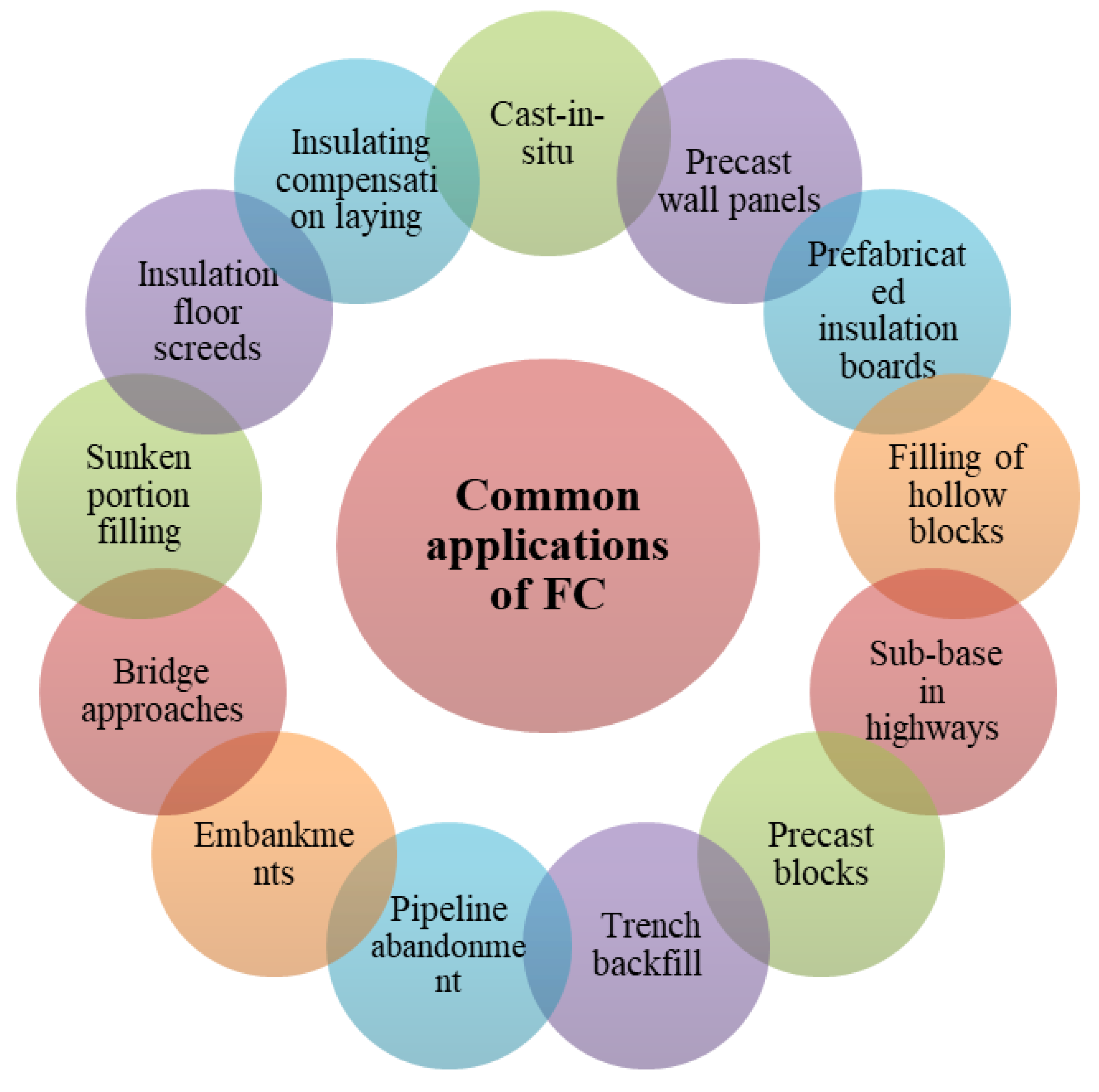
7.1. FC Utilizations

Due to the practical and manufacturing unusualness of many experts and the difficulty of attaining structural strength in the last 60 years, FC has been widely ignored for usage in concrete structural applications (Table 13) [185]. In most cases, FC was employed to fill voids and used as thermal insulation and behavior as a sound damper [12,185]. Developments in mechanical and chemical bubbling methods, admixtures of concrete, and other additives considerably amended FC’s constancy and hardened characteristics [186,187]. Simultaneously, the appropriate use of FC for structural concrete uses is well-known, and many investigative works have concentrated on increasing mechanical characteristics [10,12,13,14,45,53,185,186,187,188]. However, FC’s application has been noticeable as widespread applications internationally, particularly in the areas of distress from housing scarcities or endangered to adverse climate, storms, and tremors [189]. FC could be made with a range of dry densities limited between 300 and 1850 kg/m³, with 28-day strengths of about 1 and 58 N/mm², respectively [1]. FC has a superior function at resisting fire and its acoustical and thermal insulation characteristic marks it perfect for an extensive range of applications, from void filling to insulating roofs and floors. It is also mainly valuable for ditch restoration [12]. In addition, many other typical uses of FC are applied under concrete pavement, to avoid ice lurch in road and rail networks, to protect narrow foundation structures and placements, to avert ice lurch underneath pile caps and ice jacking of thin piles, to apply (as a mortar) to seal unrestricted tubes and as backfill under suppressed oil ground components, to reduce the heat under warm oil containers and the reservoir seats, to block cavities under floors, and to decrease the thermal gradient and the thermal stress in warm concrete pits (and, consequently, protect shallow) [185]. In Arab countries, the beneficial characteristics of FC, such as its lightweight nature and thermal insulation., It can be used as appropriate material to decrease the negative influence of earthquakes, and resolve the adverse consequence of the changes in temperature [1]. Further, FC applications are economical concerning repair, retrofitting, strengthening, and rehabilitating concrete structures [157].

7.2. Future Improvement

Kum [115] found that shrinkage cracking, which developed in the FC, may become an issue in the future of material research. Creep strain is another parameter that is rarely found in current research trends. A gradual increment of strain for concrete in a function of time is referred to as a creep deformation. Long-term behavior needs to be investigated as it is affecting the overall structural performance of FC members. Creep and shrinkage prediction models should be developed for different structural concrete member design. As the concrete matrix of lightweight aggregate concrete varies with FC, the interaction of steel reinforcements and a concrete matrix may also exhibit different structural performance. The pores minimize this interaction, which may result in slipping between these two materials.
For shear behavior of a reinforced beam, the design remains in doubt for structural members. For the deflection check and crack control, there remains uncertainty for further investigations. As found in previous research, the cracks were found more than normal weight concrete at ultimate strength, and led to excessive deformation of reinforced FC structures. Confinement with steel strap or other materials may mechanically increase the member capacity while reducing cracks at the serviceability state.
The large volume of voids may promote electrochemical movement and prevent the passive layer [190]. Therefore, corrosion may take place and reduce the strength of RFC. The research direction of this passive layer is essential in assisting designers for reliable FC building construction.
A life cycle assessment has been done for lightweight aggregate concrete blocks in China’s production [191]. From the life cycle stages of raw material achievement, production, use/recycle/repairs, and reutilize/waste management [191,192], lightweight concrete seems to require less energy, which leads to more sustainable practice. Other research also highlighted the environmental impacts of FC production [193]. Reducing the carbon footprint was discovered and found more sustainable than autoclaved aerated concrete for wall construction [193]. Therefore, it is important to identify lightweight FC’s sustainability through a life cycle assessment, as it is claimed as a green constructional material.

8. Conclusions

Although the FC’s properties have been rigorously investigated, the application for reinforced foamed concrete is yet to be exposed. During the comprehensive review, FC properties have been summarized to determine its feasibility on the application in various types of structural use. Other properties were evaluated and equated with the normal weight concrete; however, its prediction models have yet to be developed. The properties of FC can be summarized accordingly, where the compressive strength values were greater than 40 MPa at 28 days, but was marginally achievable for structural use with >17 MPa.
-
Elastic modulus: four-times lower than normal concrete, which justified that there are more cracks during serviceability state;
-
Splitting tensile strength: non-loading cracks from pore formation may induce lower tensile strength, minimum permissible strength of 2 MPa is suggested by ASTM C330;
-
Time dependency properties: all prediction models, GL2000, ACI 209, SAK and CEB MC90, failed to estimate the drying shrinkage and specific creep of FC without aggregate;
-
Bond strength: generally lower than normal concrete, but able to be applied in RFC design.
Due to limitations in design specifications, this review paper also summarizes the nuances of designing structural members with RFC. It can be concluded that, in this stage, for RFC design, only ACI 318 offers suggestions for reduction factors in ultimate limit design for beam shear capacity. For deflection and crack control, Eurocode 2 should be adopted for FC design. Both designs, through ultimate and serviceability limit states, should be performed, as cracks may be found often in FC. Proposed reduction factors should be adapted to the RFC design for safety consideration. Compression members are suggested to be investigated, especially creep and shrinkage, before confident design can be obtained. Currently, reduction factors of 0.75 are proposed for shear, torsion, and compression, while 0.60 and 0.70 for flexural and deflection control respectively.
Some issues need to be concentrated in future research direction for securing more reliable design. In revealing RFC’s behavior, it is suggested to perform bond properties of reinforcement bar and FC with various densities, which are rarely found in the current research trend. Comprehensive environmental research on RFC should also be performed as it is potentially reducing the carbon footprint in the construction industry. However, the environmental impacts should be identified and possibly quantified.

Author Contributions

Conceptualization, M.A., Y.Y.L., S.P.-N., Y.Y.L., and R.F.; methodology, Y.H.L., R.F., Y.H.L., G.M., and M.A.; validation, Y.H.L., S.P.-N., Y.Y.L., and R.F.; resources, M.A., R.F., N.V., S.P.-N., Y.Y.L., and Y.H.L.; data curation, M.A., Y.H.L., S.P.-N., and F.F.; writing—original draft preparation, M.A., R.F., S.P.-N., Y.Y.L., and Y.H.L.; writing—review and editing, N.V. and G.M.; supervision, M.A., R.F., Y.H.L., and S.P.-N.; project administration, M.A., R.F., and N.V.; funding acquisition, N.V. All authors have read and agreed to the published version of the manuscript.

Funding

This research was supported by Peter the Great St. Petersburg Polytechnic University, Russian Academic Excellence Project ‘5-100′.

Acknowledgments

The authors gratefully acknowledge the financial support by Peter the Great Polytechnic University, Saint Petersburg, Russia, the supervision and guidance by the Deanship of Scientific Research at Prince Sattam bin Abdulaziz University, Alkharj, Saudi Arabia, and the cooperation of the Department of Civil Engineering, Faculty of Engineering and IT, Amran University, Yemen, for this research.

Conflicts of Interest

The authors declare no conflict of interest.

References

  1. Amran, Y.H.M.; Farzadnia, N.; Ali, A.A.A. Properties and applications of foamed concrete: A review. Constr. Build. Mater. 2015, 101, 990–1005. [Google Scholar] [CrossRef]
  2. Amran, Y.H.M. Influence of structural parameters on the properties of fibred-foamed concrete. Innov. Infrastruct. Solut. 2020, 5, 1–18. [Google Scholar] [CrossRef]
  3. Mugahed Amran, Y.H. Determination of Structural Behavior of Precast Foamed Concrete Sandwich Panel. Ph.D. Thesis, Universiti Putra Malaysia (UPM), Serdang, Malaysia, 2016. [Google Scholar]
  4. Mohamad, N.; Hassan, N. The structural performance of precast lightweight foam concrete sandwich panel with single and double shear truss connectors subjected to axial load. Adv. Mater. Res. 2013, 634, 2746–2751. [Google Scholar] [CrossRef] [Green Version]
  5. Mohamad, N.; Omar, W.; Abdullah, R. Structural Behaviour of Precast Lightweight Foamed Concrete Sandwich Panel as a Load Bearing Wall. OIDA Int. J. Sustain. Dev. 2012, 5, 49–58. [Google Scholar]
  6. Hamad, A.J. Materials, Production, Properties and Application of Aerated Lightweight Concrete: Review. Int. J. Mater. Sci. Eng. 2014, 2, 152–157. [Google Scholar] [CrossRef]
  7. Lesovik, V.; Voronov, V.; Glagolev, E.; Fediuk, R.; Alaskhanov, A.; Amran, Y.H.M.; Murali, G.; Baranov, A. Improving the behaviors of foam concrete through the use of composite binder. J. Build. Eng. 2020, 31, 101414. [Google Scholar] [CrossRef]
  8. Wu, J.; Zhang, Z.; Zhang, Y.; Li, D. Preparation and characterization of ultra-lightweight foamed geopolymer (UFG) based on fly ash-metakaolin blends. Constr. Build. Mater. 2018, 168, 771–779. [Google Scholar] [CrossRef]
  9. Raj, A.; Sathyan, D.; Mini, K.M. Physical and functional characteristics of foam concrete: A review. Constr. Build. Mater. 2019, 221, 787–799. [Google Scholar] [CrossRef]
  10. Mugahed Amran, Y.H.; Muhammad Rashid, R.S.; Hejazi, F.; Safiee, N.A.; Abang Ali, A.A. Structural behavior of laterally loaded precast foamed concrete sandwich panel. Int. J. Civ. Environ. Struct. Constr. Archit. Eng. 2016, 10, 255–263. [Google Scholar]
  11. Amran, Y.H.M.; Rashid, R.S.M.; Hejazi, F.; Safiee, N.A.; Ali, A.A.A. Structural Behavior of Precast Foamed Concrete Sandwich Panel Subjected to Vertical In-Plane Shear Loading. J. Civ. Environ. Struct. Constr. Arch. Eng. 2016, 10, 699–708. [Google Scholar]
  12. Mugahed Amran, Y.H.; Abang Ali, A.A.; Rashid, R.S.M.; Hejazi, F.; Safiee, N.A. Structural behavior of axially loaded precast foamed concrete sandwich panels. Constr. Build. Mater. 2016, 107, 307–320. [Google Scholar] [CrossRef]
  13. Amran, Y.H.M.; Rashid, R.S.M.; Hejazi, F.; Safiee, N.A.; Ali, A.A.A. Response of precast foamed concrete sandwich panels to flexural loading. J. Build. Eng. 2016, 7, 143–158. [Google Scholar] [CrossRef]
  14. Mugahed Amran, Y.H.; Alyousef, R.; Alabduljabbar, H.; Alrshoudi, F.; Rashid, R.S.M. Influence of slenderness ratio on the structural performance of lightweight foam concrete composite panel. Case Stud. Constr. Mater. 2019, 10, e00226. [Google Scholar] [CrossRef]
  15. Kim, H.K.; Jeon, J.H.; Lee, H.K. Workability, and mechanical, acoustic and thermal properties of lightweight aggregate concrete with a high volume of entrained air. Constr. Build. Mater. 2012, 29, 193–200. [Google Scholar] [CrossRef]
  16. Ganesan, S.; Othuman Mydin, M.A.; Mohd Yunos, M.Y.; Mohd Nawi, M.N. Thermal Properties of Foamed Concrete with Various Densities and Additives at Ambient Temperature. Appl. Mech. Mater. 2015, 747, 230–233. [Google Scholar] [CrossRef]
  17. Neramitkornburi, A.; Horpibulsuk, S.; Shen, S.L.; Chinkulkijniwat, A.; Arulrajah, A.; Disfani, M.M. Durability against wetting-drying cycles of sustainable lightweight cellular cemented construction material comprising clay and fly ash wastes. Constr. Build. Mater. 2015, 77, 41–49. [Google Scholar] [CrossRef]
  18. Raut, S.P.; Ralegaonkar, R.V.; Mandavgane, S.A. Development of sustainable construction material using industrial and agricultural solid waste: A review of waste-create bricks. Constr. Build. Mater. 2011, 25, 4037–4042. [Google Scholar] [CrossRef]
  19. Madurwar, M.V.; Ralegaonkar, R.V.; Mandavgane, S.A. Application of agro-waste for sustainable construction materials: A review. Constr. Build. Mater. 2013, 38, 872–878. [Google Scholar] [CrossRef]
  20. Amran, Y.H.M.; Gutierrez, M.; Alyousef, R.; El-zeadani, M.; Alabduljabbar, H.; Aune, V. Performance investigation of high-proportion Saudi-fly-ash-based concrete. Results Eng. 2020, 6, 100118. [Google Scholar] [CrossRef]
  21. César Maruyama, R.; Camarini, G. Properties of Cellular Concrete for Filters. Int. J. Eng. Technol. 2015, 7, 223–228. [Google Scholar] [CrossRef] [Green Version]
  22. Papadopoulos, A.M.; Giama, E. Environmental performance evaluation of thermal insulation materials and its impact on the building. Build. Environ. 2007, 42, 2178–2187. [Google Scholar] [CrossRef]
  23. Thakrele, M.H. Experimental study on foam concrete. Int. J. Civ. Struct. Environ. Infrastruct. Eng. Res. Dev. 2014, 4, 145–158. [Google Scholar]
  24. Mays-mcsi, C.V. Lightweight Flowable Fill (Cellular Concrete); MAYS Construction Specialties Inc.: Grand Junction, CO, USA, 2020; Volume 1. [Google Scholar]
  25. Abd Saloum, Q.; Zaid Abdullah, M.; Adnan Hashim, A. The Preparation of Foam Cement and Determining Some of Its Properties. Eng. Technol. J. 2015, 33, 61–69. [Google Scholar] [CrossRef]
  26. Hajek, M.; Decky, M.; Drusa, M.; Orininová, L.; Scherfel, W. Elasticity Modulus and Flexural Strength Assessment of Foam Concrete Layer of Poroflow. In IOP Conference Series: Earth and Environmental Science; IOP Publishing: Bristol, UK, 2016. [Google Scholar]
  27. Oginni, F. Continental Application of Foamed Concrete Technology: Lessons for Infrastructural Development in Africa. Br. J. Appl. Sci. Technol. 2015, 5, 417–424. [Google Scholar] [CrossRef]
  28. Zhao, X.; Lim, S.K.; Tan, C.S.; Li, B.; Ling, T.C.; Huang, R.; Wang, Q. Properties of foamed mortar prepared with granulated blast-furnace slag. Materials 2015, 8, 462–473. [Google Scholar] [CrossRef] [Green Version]
  29. Lim, S.K.; Tan, C.S.; Chen, K.P.; Lee, M.L.; Lee, W.P. Effect of different sand grading on strength properties of cement grout. Constr. Build. Mater. 2013, 38, 348–355. [Google Scholar] [CrossRef]
  30. Lee, Y.H.; Lim, M.H.; Lee, Y.L.; Lee, Y.Y.; Tan, C.S.; Mohammad, S.; Ma, C.K. Compressive strength of lightweight foamed concrete with charcoal as a sand replacement. Indian J. Eng. Mater. Sci. 2018, 25, 98–108. [Google Scholar] [CrossRef]
  31. Lee, Y.L. Structural Behaviour of Slab Panel System with Embedded Cold-Formed Steel Skeletal Frame. Ph.D. Thesis, Universiti Teknologi Malaysia, Johor, Malaysia, 2016. [Google Scholar]
  32. Lim, S.K.; Tan, C.S.; Li, B.; Ling, T.C.; Hossain, M.U.; Poon, C.S. Utilizing high volumes quarry wastes in the production of lightweight foamed concrete. Constr. Build. Mater. 2017, 151, 441–448. [Google Scholar] [CrossRef]
  33. Saman, M. Performance of Foamed Concrete with Waste Paper Sludge Ash (Wpsa) and Fine Recycled Concrete Aggregate (Frca) Contents. Int. Sustain. Civ. Eng. J. 2012, 1, 19–27. [Google Scholar] [CrossRef]
  34. Ikponmwosa, E.; Fapohunda, C.; Kolajo, O.; Eyo, O. Structural behaviour of bamboo-reinforced foamed concrete slab containing polyvinyl wastes (PW) as partial replacement of fine aggregate. J. King Saud Univ. Eng. Sci. 2017, 29, 348–355. [Google Scholar] [CrossRef] [Green Version]
  35. Hadipramana, J.; Samad, A.A.A.; Zaidi, A.M.A.; Mohammad, N.; Riza, F.V. Effect of uncontrolled burning rice husk ash in foamed concrete. In Advanced Materials Research; Trans Tech Publications Ltd.: Stafa-Zurich, Switzerland, 2013. [Google Scholar]
  36. Singh, M.; Siddique, R. Strength properties and micro-structural properties of concrete containing coal bottom ash as partial replacement of fine aggregate. Constr. Build. Mater. 2014, 50, 246–256. [Google Scholar] [CrossRef]
  37. Akhund, M.A.; Khoso, A.R.; Pathan, A.A.; Memon, U.; Siddiqui, F.H. Influence of biomass aggregate on strength of foam concrete. Int. J. Civ. Eng. Technol. 2017, 8, 1645–1653. [Google Scholar]
  38. Lim, S.K.; Tan, C.S.; Zhao, X.; Ling, T.C. Strength and toughness of lightweight foamed concrete with different sand grading. KSCE J. Civ. Eng. 2014, 19, 2191–2197. [Google Scholar] [CrossRef] [Green Version]
  39. Balasundaram, M. Experimental Study on Light Weight Foam Concrete Bricks. Int. Res. J. Eng. Technol. 2017, 4, 677–686. [Google Scholar]
  40. Hajimohammadi, A.; Ngo, T.; Kashani, A. Sustainable one-part geopolymer foams with glass fines versus sand as aggregates. Constr. Build. Mater. 2018, 171, 223–231. [Google Scholar] [CrossRef]
  41. Boon, K.H.; Loon, L.Y.; Chuan, D.Y.E. Compressive Strength and Shrinkage of Foamed. Concet 2006, 12, 1–8. [Google Scholar]
  42. Tiong, H.Y.; Lim, S.K.; Lee, Y.L.; Lim, J.H. Engineering Properties of 1200 kg/m Lightweight Foamed Concrete with Egg Shell Powder as Partial Replacement Material of Cement. In E3S Web of Conferences; EDP Sciences: Paris, France, 2018. [Google Scholar]
  43. Lim, S.K.; Tan, C.S.; Lim, O.Y.; Lee, Y.L. Fresh and hardened properties of lightweight foamed concrete with palm oil fuel ash as filler. Constr. Build. Mater. 2013, 46, 39–47. [Google Scholar] [CrossRef]
  44. Hajimohammadi, A.; Ngo, T.; Mendis, P.; Nguyen, T.; Kashani, A.; van Deventer, J.S.J. Pore characteristics in one-part mix geopolymers foamed by H2O2: The impact of mix design. Mater. Des. 2017, 130, 381–391. [Google Scholar] [CrossRef]
  45. Ramamurthy, K.; Kunhanandan Nambiar, E.K.; Indu Siva Ranjani, G. A classification of studies on properties of foam concrete. Cem. Concr. Compos. 2009, 31, 388–396. [Google Scholar] [CrossRef]
  46. Kearsley, E.P.; Wainwright, P.J. The effect of high fly ash content on the compressive strength of foamed concrete. Cem. Concr. Res. 2001, 31, 105–112. [Google Scholar] [CrossRef]
  47. Sargent, P. The development of alkali-activated mixtures for soil stabilisation. In Handbook of Alkali-Activated Cements, Mortars and Concretes; Woodhead Publishing: Cambridge, UK, 2015; ISBN 9781782422884. [Google Scholar]
  48. Black, L. Low clinker cement as a sustainable construction material. In Sustainability of Construction Materials; Woodhead Publishing: Cambridge, UK, 2016. [Google Scholar]
  49. Hussin, M.W.; Abdullah, K. Properties Of Palm Oil Fuel Ash Cement Based Aerated Concrete Panel Subjected To Different Curing Regimes. Malaysian J. Civ. Eng. 2009, 21, 17–31. [Google Scholar]
  50. Zhang, Y.J.; Kang, L.; Liu, L.C. Alkali-activated cements for photocatalytic degradation of organic dyes. In Handbook of Alkali-Activated Cements, Mortars and Concretes; Woodhead Publishing: Cambridge, UK, 2015; ISBN 9781782422884. [Google Scholar]
  51. Panesar, D.K. Cellular concrete properties and the effect of synthetic and protein foaming agents. Constr. Build. Mater. 2013, 44, 575–584. [Google Scholar] [CrossRef]
  52. Jones, M.R.; McCarthy, A. Behaviour and assessment of foamed concrete for construction applications. In Use of Foamed Concrete in Construction, Proceedings of the International Conference, Scotland, UK, 5 July 2005; Thomas Telford Publishing: London, UK, 2005. [Google Scholar]
  53. Aldridge, D. Introduction to foamed concrete: What, why, how? In Use of Foamed Concrete in Construction, Proceedings of the International Conference, Scotland, UK, 5 July 2005; Thomas Telford Publishing: London, UK, 2005. [Google Scholar]
  54. Nambiar, E.K.K.; Ramamurthy, K. Influence of filler type on the properties of foam concrete. Cem. Concr. Compos. 2006. [Google Scholar] [CrossRef]
  55. Atoyebi, O.D.; Odeyemi, S.O.; Bello, S.A.; Ogbeifun, C.O. Splitting Tensile Strength Assessment of Lightweight Foamed Concrete Reinforced with Waste Tyre Steel Fibres. Int. J. Civ. Eng. Technol. 2018, 9, 1129–1137. [Google Scholar]
  56. Niaounakis, M. Biopolymers: Processing and Products; William Andrew: Norwich, NY, USA, 2014; ISBN 9780323279383. [Google Scholar]
  57. Tan, X.; Chen, W.; Hao, Y.; Wang, X. Experimental study of ultralight (<300 kg/m3) foamed concrete. Adv. Mater. Sci. Eng. 2014. [Google Scholar] [CrossRef] [Green Version]
  58. Bing, C.; Zhen, W.; Ning, L. Experimental Research on Properties of High-Strength Foamed Concrete. J. Mater. Civ. Eng. 2012, 24, 113–118. [Google Scholar] [CrossRef]
  59. Tikalsky, P.J.; Pospisil, J.; MacDonald, W. A method for assessment of the freeze-thaw resistance of preformed foam cellular concrete. Cem. Concr. Res. 2004, 34, 889–893. [Google Scholar] [CrossRef]
  60. Richard, A. Experimental Production of Sustainable Lightweight Foamed Concrete. Br. J. Appl. Sci. Technol. 2013, 3, 994–1005. [Google Scholar] [CrossRef]
  61. Wu, X.; Li, C.; Zhao, C.; Sheng, Y.; Lu, S. The Synthesis of an Aqueous Film Forming Foam Concentration and the Drainage Characteristic of the Foam. In International Conference on Circuits and Systems; Atlantis Press: Paris, France, 2015. [Google Scholar]
  62. Welker, C.D.; Welker, M.A.; Welker, M.F.; Justman, M.A.; Hendricksen, R.S. Foamed Concrete Compositional Process. U.S. Patent 6,153,005, 28 November 2000. [Google Scholar]
  63. Byun, K.J.; Song, H.W.; Park, S.S. Development of structural lightweight foamed concrete using polymer foam agent. In ICPIC ’98. International Congress on Polymers in Concrete; Casma: Ica, Peru, 1998. [Google Scholar]
  64. Wee, T.H.; Babu, D.S.; Tamilselvan, T.; Lim, H.S. Air-void system of foamed concrete and its effect on mechanical properties. ACI Mater. J. 2006, 103. [Google Scholar] [CrossRef]
  65. Van Deijk, S. Foam concrete. Concrete 1991, 25, 49–54. [Google Scholar]
  66. Kolias, S.; Georgiou, C. The effect of paste volume and of water content on the strength and water absorption of concrete. Cem. Concr. Compos. 2005, 27, 211–216. [Google Scholar] [CrossRef]
  67. Kearsley, E.P.; Wainwright, P.J. Porosity and permeability of foamed concrete. Cem. Concr. Res. 2001, 31, 805–812. [Google Scholar] [CrossRef]
  68. Roslan, A.F.; Awang, H.; Mydin, M.A.O. Effects of various additives on drying shrinkage, compressive and flexural strength of lightweight foamed concrete (LFC). In Advanced Materials Research; Trans Tech Publications Ltd.: Stafa-Zurich, Switzerland, 2013. [Google Scholar]
  69. Kunhanandan Nambiar, E.K.; Ramamurthy, K. Fresh state characteristics of foam concrete. J. Mater. Civ. Eng. 2008, 20, 111–117. [Google Scholar] [CrossRef]
  70. McCormick, F.C. A Rational Procedure for Proportioning Pre-Formed foam Cellular Concrete Mixes. Ph.D. Thesis, University of Michigan, Ann Arbor, MI, USA, 1964. [Google Scholar]
  71. Odler, I.; Rößler, M. Investigations on the relationship between porosity, structure and strength of hydrated Portland cement pastes. II. Effect of pore structure and of degree of hydration. Cem. Concr. Res. 1985, 15, 401–410. [Google Scholar] [CrossRef]
  72. Rößler, M.; Odler, I. Investigations on the relationship between porosity, structure and strength of hydrated portland cement pastes I. Effect of porosity. Cem. Concr. Res. 1985, 15, 320–330. [Google Scholar] [CrossRef]
  73. Li, W.; Guo, Z. Experimental investigation of strength and deformation of concrete at elevated temperature. J. Build. Struct. 1993, 1, 8–16. [Google Scholar]
  74. Wan Ibrahim, M.H.; Jamaludin, N.; Irwan, J.M.; Ramadhansyah, P.J.; Suraya Hani, A. Compressive and flexural strength of foamed concrete containing polyolefin fibers. In Advanced Materials Research; Trans Tech Publications Ltd.: Stafa-Zurich, Switzerland, 2014. [Google Scholar]
  75. Tiong, H.Y.; Lim, S.K.; Lim, J.H. Strengths and sorptivity of lightweight foamed concrete with crushed steel slag. J. Built Environ. Technol. Eng. 2017, 3, 37–48. [Google Scholar]
  76. Tiong, H.Y.; Lim, S.K.; Lim, J.H. Strength Properties of Foamed Concrete Containing Crushed Steel Slag as Partial Replacement of Sand with Specific Gradation. In MATEC Web of Conferences; EDP Sciences: Paris, France, 2017. [Google Scholar]
  77. Hilal, A.A.; Thom, N.H.; Dawson, A.R. On void structure and strength of foamed concrete made without/with additives. Constr. Build. Mater. 2015, 85, 157–164. [Google Scholar] [CrossRef]
  78. ASTM C1437-13. Standard Test Method for Flow of Hydraulic Cement Mortar; ASTM International: West Conshohocken, PA, USA, 2013. [Google Scholar]
  79. ASTM C1611/C1611M-14. Standard Test Method for Slump Flow of Self-Consolidating Concrete; ASTM International: West Conshohocken, PA, USA, 2014. [Google Scholar]
  80. Tan, C.S.; Lee, Y.L.; Mohammad, S.; Lim, S.K.; Lee, Y.H.; Lim, J.H. Flexural behaviour of reinforced slab panel system with embedded cold-formed steel frames as reinforcement. J. Teknol. 2015, 74. [Google Scholar] [CrossRef] [Green Version]
  81. Meilin, P. Development of Structural Grade Foamed Concrete; University of Dundee: Dundee, UK, 1999. [Google Scholar]
  82. Narayanan, N. Influence of Composition on the Structure and Properties of Aerated Concrete. Master’s. Thesis, IIT Madras, Tamil Nadu, India, 1999. [Google Scholar]
  83. Dhir, R.; Jones, M.; Nicol, L. Development of Structural Grade Foamed Concrete; DETR Research Project; University of Dundee: Dundee, UK, 1999. [Google Scholar]
  84. Brewer, W.E. Controlled low strength materials (CLSM). In Radical Concrete Technology; Dhir, R.K., Hewlett, P.C., Eds.; E and FN Spon: New York, NY, USA, 1996; pp. 655–667. [Google Scholar]
  85. Gowri, R.; Anand, K.B. Experimental Study on Fresh State Characteristics of Foam Concrete with Ultrafine GGBS. Int. J. Innov. Res. Sci. Eng. Technol. (IJIRSET) 2016, 5, 160–167. [Google Scholar]
  86. Jones, M.R.; Zheng, L.; Ozlutas, K. Stability and instability of foamed concrete. Mag. Concr. Res. 2016, 68, 542–549. [Google Scholar] [CrossRef] [Green Version]
  87. Kuzielová, E.; Pach, L.; Palou, M. Effect of activated foaming agent on the foam concrete properties. Constr. Build. Mater. 2016, 125, 998–1004. [Google Scholar] [CrossRef]
  88. Cong, M.; Bing, C. Properties of a foamed concrete with soil as filler. Constr. Build. Mater. 2015, 76, 61–69. [Google Scholar] [CrossRef]
  89. Matalkah, F.; Bharadwaj, H.; Balachandra, A.; Soroushian, P. Aerated Concrete Produced Using Locally Available Raw Materials. Civ. Eng. J. 2017, 3, 214–220. [Google Scholar] [CrossRef]
  90. Dhir, R.; Hewlett, P. Concrete in the Service of Mankind: Radical Concrete Technology; CRC Press: Boca Raton, FL, USA, 2014. [Google Scholar]
  91. Krishnan, G.; Anand, K.B. Industrial waste utilization for foam concrete. In IOP Conference Series: Materials Science and Engineering; IOP Publishing: Bristol, UK, 2018. [Google Scholar]
  92. Perlite Insulating Concrete. ACI J. Proc. 1954. [CrossRef]
  93. Mikulica, K.; Labaj, M.; Hela, R. Rehabilitation of Floor Structures Using Foam Concrete. Proc. Eng. 2017, 195, 108–113. [Google Scholar] [CrossRef]
  94. Vardhan, R.; Chandel, S.; Sakale, R. Study of Cellular Light Weight Concrete. IJSRD Int. J. Sci. Res. Dev. 2016, 4, 1–6. [Google Scholar]
  95. McCormick, F.C. Rational proportioning of preformed foam cellular concrete. J. Proc. 1967, 64, 104–110. [Google Scholar]
  96. Kearsley, E.P.; Wainwright, P.J. The effect of porosity on the strength of foamed concrete. Cem. Concr. Res. 2002, 32, 233–239. [Google Scholar] [CrossRef]
  97. Namsone, E.; Šahmenko, G.; Korjakins, A.; Namsone, E. Influence of Porous Aggregate on the Properties of Foamed Concrete. Constr. Sci. 2017, 19. [Google Scholar] [CrossRef]
  98. Ibrahim, N.M.; Salehuddin, S.; Amat, R.C.; Rahim, N.L.; Izhar, T.N.T. Performance of Lightweight Foamed Concrete with Waste Clay Brick as Coarse Aggregate. Apcbee Procedia 2013, 5, 497–501. [Google Scholar] [CrossRef] [Green Version]
  99. Falade, F.; Ikponmwosa, E.; Fapohunda, C. A Study on the Compressive and Tensile Strength of Foamed Concrete Containing Pulverized Bone as a Partial Replacement of Cement. J. Engg. Appl. Sci 2013, 13, 82–93. [Google Scholar]
  100. Mastali, M.; Kinnunen, P.; Isomoisio, H.; Karhu, M.; Illikainen, M. Mechanical and acoustic properties of fiber-reinforced alkali-activated slag foam concretes containing lightweight structural aggregates. Constr. Build. Mater. 2018, 187, 371–381. [Google Scholar] [CrossRef]
  101. Mugahed Amran, Y.H.; Alyousef, R.; Alabduljabbar, H.; Khudhair, M.H.R.; Hejazi, F.; Alaskar, A.; Alrshoudi, F.; Siddika, A. Performance properties of structural fibred-foamed concrete. Results Eng. 2020, 5, 100092. [Google Scholar] [CrossRef]
  102. Van Zijl, G.P.A.G.; Van Rooyen, A.S.; Mubatapasango, M.S.; Dunn, T.P.A.; Grafe, J. Durability and bond of reinforced lightweight foamed concrete. In High Tech Concrete: Where Technology and Engineering Meet—Proceedings of the 2017 Fib Symposium; Springer: Cham, Switzerland, 2017. [Google Scholar]
  103. Alengaram, U.J.; Al Muhit, B.A.; Jumaat, M.Z. Bin Utilization of oil palm kernel shell as lightweight aggregate in concrete—A review. Constr. Build. Mater. 2013, 38, 161–172. [Google Scholar] [CrossRef]
  104. Pichler, B.; Hellmich, C.; Eberhardsteiner, J.; Wasserbauer, J.; Termkhajornkit, P.; Barbarulo, R.; Chanvillard, G. Effect of gel-space ratio and microstructure on strength of hydrating cementitious materials: An engineering micromechanics approach. Cem. Concr. Res. 2013, 45, 55–68. [Google Scholar] [CrossRef]
  105. Durack, J.M.; Weiqing, L. The properties of foamed air cured fly ash based concrete for masonry production. In Proceedings of the Fifth Australasian Masonry Conference, Gladstone, Australia, 1–3 July 1998. [Google Scholar]
  106. Neville, A. Properties of Concrete, 5th ed.; Pearson Education Limited: London, UK, 2012; ISBN 9780273755807. [Google Scholar]
  107. Brady, K.C.; Watts, G.R.A.; Jones, M.R. Specification for Foamed Concrete; TRL Limited: Crowthorne, UK, 2001. [Google Scholar]
  108. Falade, F.; Ikponmwosa, E.; Fapohunda, C. Flexural performance of foam concrete containing pulverized bone as partial replacement of cement. Maejo Int. J. Sci. Technol. 2014. [Google Scholar] [CrossRef]
  109. Jones, M.R.; McCarthy, A. Preliminary views on the potential of foamed concrete as a structural material. Mag. Concr. Res. 2005, 57, 21–31. [Google Scholar] [CrossRef]
  110. Jones, M.R.; McCarthy, A. Utilising unprocessed low-lime coal fly ash in foamed concrete. Fuel 2005, 4, 1398–1409. [Google Scholar] [CrossRef]
  111. Mydin, M.A.O.; Wang, Y.C. Mechanical properties of foamed concrete exposed to high temperatures. Constr. Build. Mater. 2012, 26, 638–654. [Google Scholar] [CrossRef]
  112. Saint-Jalmes, A.; Peugeot, M.L.; Ferraz, H.; Langevin, D. Differences between protein and surfactant foams: Microscopic properties, stability and coarsening. Colloids Surf. A Physicochem. Eng. Asp. 2005, 263, 219–225. [Google Scholar] [CrossRef]
  113. Guide For Cellular Concretes above 50 pcf and for Aggregate Concretes above 50 pcf with Compressive Strengths Less Than 2500 psi; American Concrete Institute: Detroit, MI, USA, 1993.
  114. Raupit, F.; Saggaff, A.; Tan, C.S.; Lee, Y.L.; Tahir, M.M. Splitting tensile strength of lightweight foamed concrete with polypropylene fiber. Int. J. Adv. Sci. Eng. Inf. Technol. 2017, 7, 424. [Google Scholar] [CrossRef]
  115. Kum, Y.J. Cracking Mode and Shear Strength of Lightweight Concrete Beams. Ph.D. Thesis, National University Singapore, Singapore, 2011. [Google Scholar]
  116. ASTM C330/C330M. Standard Specification for Lightweight Aggregates for Structural Concrete; ASTM International: West Conshohocken, PA, USA, 2017. [Google Scholar]
  117. Rahman, N.A.; Jaini, Z.M.; Zahir, N.N.M. Fracture energy of foamed concrete by means of the three-point bending tests on notched beam specimens. ARPN J. Eng. Appl. Sci. 2015, 10, 6562–6570. [Google Scholar]
  118. Jaini, Z.M.; Abd Rahman, N.; Rum, R.H.M.; Haurula, M.M. Fracture Energy of Foamed Concrete: Numerical Modelling Using the Combined Finite-Discrete Element Method. In MATEC Web of Conferences; EDP Sciences: Paris, France, 2017. [Google Scholar]
  119. Narayanan, N.; Ramamurthy, K. Structure and properties of aerated concrete: A review. Cem. Concr. Compos. 2000, 22, 321–329. [Google Scholar] [CrossRef]
  120. Hilal, A.A.; Thorn, N.H.; Dawson, A.R. Failure mechanism of foamed concrete made with/without additives and lightweight aggregate. J. Adv. Concr. Technol. 2016, 14, 511–520. [Google Scholar] [CrossRef] [Green Version]
  121. Hadipramana, J.; Samad, A.A.A.; Zaidi, A.M.A.; Mohammad, N.; Ali, N. Contribution of polypropylene fibre in improving strength of foamed concrete. In Advanced Materials Research; Trans Tech Publications Ltd.: Stafa-Zurich, Switzerland, 2013. [Google Scholar]
  122. Hulimka, J.; Krzywoń, R.; Jȩdrzejewska, A. Laboratory Tests of Foam Concrete Slabs Reinforced with Composite Grid. Procedia Eng. 2017, 193, 337–344. [Google Scholar] [CrossRef]
  123. Falliano, D.; De Domenico, D.; Ricciardi, G.; Gugliandolo, E. Improving the flexural capacity of extrudable foamed concrete with glass-fiber bi-directional grid reinforcement: An experimental study. Compos. Struct. 2019, 209, 45–59. [Google Scholar] [CrossRef]
  124. Babu, D.S. Mechanical and Deformational Properties, and Shrinkage Cracking Behaviour of Lightweight Concretes. Ph.D. Thesis, National University Singapore, Singapore, 2008. [Google Scholar]
  125. Harith, I.K. Study on polyurethane foamed concrete for use in structural applications. Case Stud. Constr. Mater. 2018, 8, 79–86. [Google Scholar] [CrossRef]
  126. Gardner, N.J.; Lockman, M.J. Design provisions for drying shrinkage and creep of normal-strength concrete. Mater. J. 2001, 98, 159–167. [Google Scholar] [CrossRef]
  127. ACI Committee 209. 209R-92: Prediction of Creep, Shrinkage, and Temperature Effects in Concrete Structures; American Concrete Institute: Farmington Hills, MI, USA, 2008. [Google Scholar]
  128. Sakata, K. Prediction of concrete creep and shrinkage. In Proceedings of the 5th International RILEM Symposium, Barcelona, Spain, 6–9 September 1993; pp. 649–654. [Google Scholar]
  129. CEB-FIP Model Code 1990; Thomas Telford Ltd.: London, UK, 1993.
  130. Jones, M.; McCarthy, M. Moving Fly Ash Utilisation in Concrete Forward: A UK Perspective; University Press of Kentucky: Lexington, UK, 2003. [Google Scholar]
  131. Wei, S.; Yiqiang, C.; Yunsheng, Z.; Jones, M.R. Characterization and simulation of microstructure and thermal properties of foamed concrete. Constr. Build. Mater. 2013, 47, 1278–1291. [Google Scholar] [CrossRef]
  132. She, W.; Zhang, Y.; Jones, M.R. Three-dimensional numerical modeling and simulation of the thermal properties of foamed concrete. Constr. Build. Mater. 2014, 50, 421–431. [Google Scholar] [CrossRef]
  133. Zhang, Z.; Provis, J.L.; Reid, A.; Wang, H. Mechanical, thermal insulation, thermal resistance and acoustic absorption properties of geopolymer foam concrete. Cem. Concr. Compos. 2015, 62, 97–105. [Google Scholar] [CrossRef]
  134. Liu, M.Y.J.; Alengaram, U.J.; Jumaat, M.Z.; Mo, K.H. Evaluation of thermal conductivity, mechanical and transport properties of lightweight aggregate foamed geopolymer concrete. Energy Build. 2014, 72, 238–245. [Google Scholar] [CrossRef]
  135. Tada, S. Material design of aerated concrete-An optimum performance design. Mater. Struct. 1986, 19, 21–26. [Google Scholar] [CrossRef]
  136. ASTM A706/A706M-15 Standard Specification for Low-Alloy Steel Deformed and Plain Bars for Concrete; ASTM International: West Conshohocken, PA, USA, 2015.
  137. ASTM A615/A615M−15a Standard Specification for Deformed and Plain Carbon-Steel Bars for Concrete Reinforcement; ASTM International: West Conshohocken, PA, USA, 2015.
  138. BS, E.N. Steel for the Reinforcement of Concrete: Weldable Reinforcing Steel: General; Central Secretariat: Brussels, Belgium, 2005. [Google Scholar]
  139. BSI. Steel for the Reinforcement of Concrete: Weldable Reinforcing Steel: Bar, Coil and Decoiled Product Specification; British Standards Institution: London, UK, 2005. [Google Scholar]
  140. BSSA. Stainless Steel Bars-Reinforcement of Concrete-Requirements and Test Methods; BSI Standards Limited: Sheffield, UK, 2016. [Google Scholar]
  141. Australian/New Zealand Standard, AS/NZS 4671:2001; Steel Reinforcing Materials; Standards Australia International Ltd.: Sydney, Australia; Standards New Zealand: Wellington, New Zealand, 2001.
  142. Lee, Y.L.; Lim, J.H.; Lim, S.K.; Tan, C.S. Flexural Behaviour of Reinforced Lightweight Foamed Mortar Beams and Slabs. KSCE J. Civ. Eng. 2018, 22, 2880–2889. [Google Scholar] [CrossRef]
  143. The Building Departement (BD). Code of Practice for Structural Use of Concrete (TC); Building Department: Mongkok, Hong Kong, 2013; ISBN 0626132401. [Google Scholar]
  144. BSI. British Standards Institution Structural Use of Concrete BS8110-1:1997; BSI: London, UK, 1997. [Google Scholar]
  145. Eurocode 2: European Committee for Standardization. Design of Concrete Structures—Part 1-2: General Rules; Structural Fire Design: Brussels, Belgium, 2004. [Google Scholar]
  146. ACI Committee 318 ACI 318-14: Building Code Requirements for Structural Concrete (ACI 318-14); American Concrete Institute: Farmington Hills, MI, USA, 2014.
  147. Lee, H.S.; Ismail, M.A.; Woo, Y.J.; Min, T.B.; Choi, H.K. Fundamental study on the development of structural lightweight concrete by using normal coarse aggregate and foaming agent. Materials 2014, 7, 4536–4554. [Google Scholar] [CrossRef] [Green Version]
  148. Mo, K.H.; Alengaram, U.J.; Jumaat, M.Z. Bond properties of lightweight concrete—A review. Constr. Build. Mater. 2016, 112, 478–496. [Google Scholar] [CrossRef]
  149. De Villiers, J. Bond Behaviour of Deformed Steel Reinforcement in Lightweight Foamed Concrete. Ph.D. Thesis, Stellenbosch University, Stellenbosch, South Africa, 2015. [Google Scholar]
  150. De Villiers, J.P.; van Zijl, G.P.A.G.; van Rooyen, A.S. Bond of deformed steel reinforcement in lightweight foamed concrete. Struct. Concr. 2017, 18, 496–506. [Google Scholar] [CrossRef]
  151. De Villiers, J.; Van Zijl, G.; van Rooyen, A. Fracture of lightweight foamed concrete in evaluation of bond behaviour of steel reinforcement embedded in LWFC. In Proceedings of the 9th International Conference on Fracture Mechanics of Concrete and Concrete Structures, Berkeley, CA, USA, 29 May–1 June 2016. [Google Scholar]
  152. Pauzi, N.N.M.; Lee, Y.L.; Tan, C.S. Mechanical properties of 3:1 cement sand ratio lightweight foamed concrete interact with cold-formed steel. In Researches on Lightweight Foamed Concrete; Tan, C.S., Lim, S.K., Eds.; UTM Press: Johor, Malaysia, 2017; pp. 17–30. [Google Scholar]
  153. Hasanuddin, I.S.; Lee, Y.H.; Lim, S.K. Mechanical properties of 4:1 cement sand ratio lightweight foamed concrete interact with cold-formed steel. In Researches on Lightweight Foamed Concrete; Tan, C.S., Lim, S.K., Eds.; UTM Press: Johor, Malaysia, 2017; pp. 31–42. [Google Scholar]
  154. Shahidan, N.I.; Mohammad, S.; Lee, Y.H. Mechanical properties of 5:1 cement sand ratio lightweight foamed concrete interact with cold-formed steel. In Researches on Lightweight Foamed Concrete; Tan, C.S., Lim, S.K., Eds.; UTM Press: Johor, Malaysia, 2017; pp. 43–52. [Google Scholar]
  155. Regan, P.E. Shear in reinforced aerated concrete. Int. J. Cem. Compos. Light. Concr. 1979, 1, 47–61. [Google Scholar] [CrossRef]
  156. Ayudhya, B.I.N.; Ungkoon, Y. Bond strength of fiber reinforced polymer (FRP) bars in autoclaved aerated concrete (AAC). In Advances in FRP Composites in Civil Engineering; Springer: Berlin/Heidelberg, Germany, 2011. [Google Scholar]
  157. Weigler, H.; Karl, S. Structural lightweight aggregate concrete with reduced density- lightweight aggregate foamed concrete. Int. J. Cem. Compos. Light. Concr. 1980, 2, 101–104. [Google Scholar] [CrossRef]
  158. Ramezani, M.; Vilches, J.; Neitzert, T. Evaluation of the pull-out strength of galvanised steel strips in a cement-based material. J. Zhejiang Univ. Sci. A 2013, 14, 843–855. [Google Scholar] [CrossRef] [Green Version]
  159. Ramezani, M.; Vilches, J.; Neitzert, T. Pull-out behavior of galvanized steel strip in foam concrete. Int. J. Adv. Struct. Eng. 2013, 5, 24. [Google Scholar] [CrossRef] [Green Version]
  160. Ramezani, M.; Vilches, J.; Neitzert, T. Experimental and numerical analysis pull-out strength of steel strip in foam concrete. Eur. J. Environ. Civ. Eng. 2013, 17, 982–1001. [Google Scholar] [CrossRef]
  161. Farghal Maree, A.; Hilal Riad, K. Analytical and experimental investigation for bond behaviour of newly developed polystyrene foam particles’ lightweight concrete. Eng. Struct. 2014, 58, 1–11. [Google Scholar] [CrossRef]
  162. Rosli, M.F.; Rashidi, A.; Ahmed, E. The Effect of Reinforcement, Expanded Polystyrene (EPS) and The Effect of Reinforcement, Expanded Polystyrene (EPS) andThe Effect of Reinforcement, Expanded Polystyrene (EPS) and Fly Ash On The Strength of Foam Concrete. J. Civ. Eng. Sci. Technol. 2016, 2, 1–7. [Google Scholar] [CrossRef] [Green Version]
  163. Jumaat, M.Z.; Johnson Alengaram, U.; Mahmud, H. Shear strength of oil palm shell foamed concrete beams. Mater. Des. 2009, 30, 2227–2236. [Google Scholar] [CrossRef]
  164. Dunn, T.P.A. Precast Lightweight Foamed Concrete Walling, a Structural System for Low-Rise Residential Buildings. Ph.D. Thesis, Stellenbosch University, Stellenbosch, South Africa, 2017. [Google Scholar]
  165. Lytvyniak, O.; Tashak, M. The suggestions as to the calculation bearing capacity of sandwich reinforced concrete—Foamed concrete floor slabs. Acta Polytech. 2019, 59, 59–66. [Google Scholar] [CrossRef]
  166. Abd, S.M.; Ghalib, D. Flexural Behaviour of Lightweight Foamed Concrete Beams Reinforced with GFRP Bars. Civ. Eng. J. 2018, 4, 278. [Google Scholar] [CrossRef] [Green Version]
  167. Taylor, R.; Brewer, R.S. The effect of the type of aggregate on the diagonal cracking of reinforced concrete beams. Mag. Concr. Res. 1963, 15, 87–92. [Google Scholar] [CrossRef]
  168. Gerritse, A. Design considerations for reinforced lightweight concrete. Int. J. Cem. Compos. Light. Concr. 1981, 3, 57–69. [Google Scholar] [CrossRef]
  169. Kozlowski, M.; Kadela, M.; Gwozdz-Lason, M. Numerical Fracture Analysis of Foamed Concrete Beam Using XFEM Method. Appl. Mech. Mater. 2016, 837, 183–186. [Google Scholar] [CrossRef]
  170. Kozłowski, M.; Kadela, M. Combined Experimental and Numerical Study on Fracture Behaviour of Low-Density Foamed Concrete. In IOP Conference Series: Materials Science and Engineering; IOP Publishing: Bristol, UK, 2018. [Google Scholar]
  171. Jaini, Z.M.; Feng, Y.T.; Owen, D.R.J.; Mokhatar, S.N. Fracture failure of reinforced concrete slabs subjected to blast loading using the combined finite-discrete element method. Lat. Am. J. Solids Struct. 2016, 13, 1086–1106. [Google Scholar] [CrossRef] [Green Version]
  172. Lia, Q.; Wanga, H.; Zhanga, Z.; Reidb, A. Numerical simulation of porosity on thermal properties and fire resistance of foamed concrete. J. Sustain. Cem. Mater. 2013, 2, 13–19. [Google Scholar] [CrossRef] [Green Version]
  173. She, W.; Zhao, G.; Cai, D.; Jiang, J.; Cao, X. Numerical study on the effect of pore shapes on the thermal behaviors of cellular concrete. Constr. Build. Mater. 2018, 163, 113–121. [Google Scholar] [CrossRef]
  174. Sipple, M.A. High Strength Self-Compacting Foam Concrete; Initial Thesis Report; UNSW ADFA: Canberra, Australia, 2009. [Google Scholar]
  175. Allouzi, R.; Al Qatawna, A.; Al-Kasasbeh, T. Lightweight foamed concrete mixture for structural use. ACI Mater. J. 2020, 117, 99–109. [Google Scholar] [CrossRef]
  176. Park, R.; Paulay, T. Reinforced Concrete Structures; John Wiley & Sons, Inc.: Christchurch, New Zealand, 1975. [Google Scholar]
  177. Tan, J.H.; Lim, S.K.; Lim, J. Flexural behaviour of reinforced lightweight foamed concrete beams. Community Res. 2017, 27, 21–31. [Google Scholar]
  178. Thorenfeldt, E.; Stemland, H. Shear Capacity of Lightweight Concrete Beams without Shear Reinforcement. In Proceedings of the The Second International Symposium on Structural Lightweight Aggregate Concrete, Kristiansand, Norwzy, 18–22 June 2000; pp. 244–255. [Google Scholar]
  179. Regan, P.E.; Arasteh, A.R. Lightweight aggregate foamed concrete. Struct. Eng. London 1990, 68, 167–173. [Google Scholar]
  180. Zareh, M. Comparative Study of Lightweight and Normal Weight Concrete in Flexure. Master’s Thesis, Portland State University, Oregon, OR, USA, 1971. [Google Scholar]
  181. Ramirez, J.A.; Olek, J.; Malone, B.J. Shear Strength of Lightweight Reinforced Concrete Beams. In High-Performance Structural Lightweight Concrete; Ries, J.P., Holm, T., Eds.; American Concrete Institute: Farmington Hills, MI, USA, 2004; pp. 69–90. [Google Scholar]
  182. Ahmad, S.H.; Xie, Y.; Yu, T. Shear strength of reinforced lightweight concrete beams of normal and high strength concrete. Mag. Concr. Res. 1994, 46, 57–66. [Google Scholar] [CrossRef]
  183. Kado, B.; Mohammad, S.; Lee, Y.H.; Shek, P.N.; Kadir, M.A.A. Experimental investigation on temperature distribution of foamed concrete filled steel tube column under standard fire. In IOP Conference Series: Earth and Environmental Science; IOP Publishing: Bristol, UK, 2018; Volume 140. [Google Scholar]
  184. Kado, B.; Mohammad, S.; Lee, Y.; Shek, P.; Kadir, M. Temperature Analysis of Steel Hollow Column Exposed to Standard Fire. J. Struct. Technol. 2018, 3, 1–8. [Google Scholar]
  185. Markin, V.; Nerella, V.N.; Schröfl, C.; Guseynova, G.; Mechtcherine, V. Material design and performance evaluation of foam concrete for digital fabrication. Materials 2019, 12, 2433. [Google Scholar] [CrossRef] [PubMed] [Green Version]
  186. Mohd Sari, K.A.; Mohammed Sani, A.R. Applications of Foamed Lightweight Concrete. In MATEC Web of Conferences; EDP Sciences: Paris, France, 2017. [Google Scholar]
  187. Liew, A.C.M. New innovative lightweight foam concrete technology. In Use of Foamed Concrete in Construction, Proceedings of the International Conference, Scotland, UK, 5 July 2005; Thomas Telford Publishing: London, UK, 2005. [Google Scholar]
  188. Mugahed Amran, Y.H.; Rashid, R.S.M.; Hejazi, F.; Abang Ali, A.A.; Safiee, N.A.; Bida, S.M. Structural Performance of Precast Foamed Concrete Sandwich Panel Subjected to Axial Load. KSCE J. Civ. Eng. 2018, 22, 1179–1192. [Google Scholar] [CrossRef]
  189. Mindess, S. Developments in the Formulation and Reinforcement of Concrete; Woodhead Publishing: Cambridge, UK, 2019; ISBN 9780081026168. [Google Scholar]
  190. Bagheri, A.; Rastegar, M.M. Investigation of passive layer formation on steel rebars in foamed concrete. Mater. Corros. 2019, 70, 1252–1261. [Google Scholar] [CrossRef]
  191. Zhao, L.; Liu, Y.; Wang, Z.; Cui, J.; Jiang, Q.; Ma, L.; Fang, M. Life cycle assessment of lightweight aggregate concrete block. In Key Engineering Materials; Trans Tech Publications Ltd.: Stafa-Zurich, Switzerland, 2014. [Google Scholar]
  192. Lemay, L. Life Cycle Assessment of Concrete Buildings, Concrete Sustainability Report, CSR04; National Ready Mixed Concrete Association: Silver Spring, MD, USA, 2011. [Google Scholar]
  193. Namsone, E.; Korjakins, A.; Sahmenko, G.; Sinka, M. The environmental impacts of foamed concrete production and exploitation. In IOP Conference Series: Materials Science and Engineering; Iop Publishing: Bristol, UK, 2017. [Google Scholar]
Figure 1. Common applications of foam concretes (FCs).
Crystals 10 00948 g001
Figure 2. Schematic diagram of the compressed-air foam generator [61]. Reprinted with permission from [61].
Crystals 10 00948 g002
Figure 3. Procedures of (a) flow table test for base mix and (b) inverted slump test [80]. Reprinted with permission from [80].
Crystals 10 00948 g003
Figure 4. Results from previous investigation on inverted slump and flow table tests [80]. Reprinted with permission from [80].
Crystals 10 00948 g004
Figure 5. Textures of various lightweight concrete [92]. (a) OPC and ground shale, foamed with an autoclaved and aluminum powder, (b) OPC and ground shale, foamed with an autoclaved and beating, (c) a shale/lime mixes, foamed with an autoclaved and aluminum powder, (d) OPC and dust, from mix-foamed, moist cured, and an expanded shale kiln, (e) OPC only, foamed with moist cured and aluminum powder, and (f) a mix of OPC and dust from an autoclaved and expanded shale kiln. Reprinted with permission from [92].
Crystals 10 00948 g005
Figure 6. Foamed concrete slab with cold-formed steel as reinforcement [80]. Reprinted with permission from [80].
Crystals 10 00948 g006
Figure 7. Failure modes of pull-out test of FC with cold-formed steel strips [152,153,154]. Reprinted with permission from [152,153,154].
Crystals 10 00948 g007
Table 1. Effect of the grading of aggregates.
Type of Material UsedMain FindingsRefs.
Quarry wasteThe excellent bond is achieved through the finer quarry dust, which alleviated the necessity of foam’s volume for the given density of concrete. Henceforth, improved compressive strength and thermal conductivity were detected.[32]
Fine-recycled concrete aggregateThe strength is greater, up to a 10% replacement by mass of sand. Moreover, reported that the recycled sand exhibited higher porosity and water absorption than calcareous sand used.[33]
Polyvinyl wasteThe combined ferrite, alumina, and silica content of polyvinyl waste above 51.45% had the potential to produce C–S–H gel. Improved bending performance and compressive strength.[34]
Rice husk ash (RHA)Compressive strength increased with increased RHA due to its pozzolanic nature.[35]
M SandCompressive strength increased up to 60% replacement of sand with M Sand and after which it decreased.[36]
Biomass aggregatesThey observed that the biomass aggregate FC achieved the highest compressive strength at 91 days of air curing compared to normal sand in the indoor environment.[37]
Different gradations of sandFlexural strength, compressive strength, and ductility were increased with the fineness of sand.[38]
Three diverse grout binders such as quarry dust, river sand, and sea sandSpecimen with quarry dust as filler attained more density and strength than other samples, and sea sand as filler achieved relatively adjacent values of strength and density as river sand as the grout materials.[39]
Glass finesShrinkage in the concrete paste abridged. A noticeable improvement in strength at lower density was reported.[40]
Table 2. Properties of foam concrete (FC) with pozzolanic binders.
Refs.Variable of Investigation (s)Density, kg/m3Strength, MPaPerformance Index, MPa
FreshMaturedStability
Type of pozzolanic binders
[43]POFA as a sand replacement, 28-day strengthNo POFA1248–13391200–1300-5.01–5.424.11–4.36
10% POFA1326–13651287–1338-4.39–6.723.28–5.22
20% POFA1326–13651288–1300-5.05–6.313.92–4.85
[28]Granulated blast-furnace slag as cement replacement, 28-day strength100% cement-1167–1282-4.0–6.43.42–4.99
50% cement, 50% slag-1192–1298-4.2–6.63.52–5.08
[41]Pulverized fly ash (PFA) as cement replacement0 to 60% PFA-1300–1650-3.0–15.92.30–10.60
[42]Egg shell as cement replacement0, 2.5, 5, 7.5 & 10% of ES1208–12221161–12430.99–1.051.36–4.31 1.15–3.56
POFA = palm oil fuel ash. Stability = proportion of measured fresh density to measured matured density. Performance index = strength in unit density.
Table 3. Constituents of pozzolanic materials.
MineralCementPozzolanic Materials
POFAGGBFSPFA [48]ES
[49][50][28]BituminousSubbituminousLignite
CaO55–66%4%35.2%42.9%1–12%5–30%15–40%97%
SiO220–24%54%27.5%32.5%20–60%40–60%15–45%-
Al2O30–8%6%10.6%13.8%5–35%20–30%20–25%-
MgO5%3%7.1%5.8%0.43–1.17%1.21–1.76%3.1%-
POFA = palm oil fuel ash; GGBFS = ground granulated blast-furnace slag; PFA = pulverized fly ash; ES = eggshells.
Table 4. Various commercial foam agents from E-markets.
Name of Foam AgentPropertyAdvantagesDensity ofRefs.
NaturalSyntheticFoamConcrete
Genfil
Herbal resin based
-Upgraded high-yield herbal resin based foam agent
Stable foam
80 to 95 g/L115–1600 kg/m3http://www.foam-concrete.com
LithoFoam
protein based
-Improved silicone oil resistance, frost resistance
-Highly active proteins
20–180 kg/m³1600–1675 kg/m³http://www.luca-industries.com
CMX™
Synthetic based
-Performs well with a wide variety of ad-mixtures
withstand higher lifts
1.02 kg/L500–1600 kg/m³https://www.richway.com
Sakshi CLC
Synthetic Based
-Air entrainers
Set accelerator
Water Reducer
0.2–0.7 L/m³300–1300 kg/m³https://www.sakshichemsciences.in/
EABASSOC
Synthetic based
-It highly concentrated, highly efficient liquid0.3–0.6 L/m³250–1800 kg/m³https://www.eabassoc.co.uk
Varimax
Synthetic based
-To offer a variable high dilution ratio1:40150–1450 kg/m³https://www.vermillionassociates.com
LITEBUILT
Synthetic based
-Quick turn-around in the production process. No hateful or toxic fume release2–3 wt % of the mixture.300–1600 kg/m3http://www.litebuilt.com/
Table 5. Properties of FC with a different dilution of foaming agent.
Refs.Density kg/m3Volume of Foam AgentType Materials AddedCompressive Strength at 28 Days *
(MPa)
By kg/m3By Dilution with Water
[63]60075–80 g/L1:33Lightweight aggregate, PP fibers, sand, and cement25–58
541–1003-0.5–3%Sludge aggregate25
[64]1000 Cement–sand1.82–16.73
[65]115075–80 g/L-Sand, fly ash, and cement10–26
[53]982–1185400.5–3%Sand, fly ash, and cement1.0–6.0
[66]650–1200401:5Sand, fly ash, cement20–43
[53]280–1200401:5Sand, fly ash, and OPC0.6–1091days
[67]800–1350401:5Silica fume (10–15%)P4.73
13800.25% Fine sand, fly ash, lime, and PP fiber15–3077days
0.2–1180days
1.6–4.6180days
[66]800–1500701:40PP fibers, sand and cement10–50
[52]701:40Course sand and OPC1.0–7.0
[46]650–1200401:5Partially (OPC-fly ash)2.0–18
[54,58]1000–150070-Fly ash, ultra-fine silica filler, and silica fume85.4365days
[68]701:5Fly ash (fine and coarse)4.0–7.37days
1.0–2.07days
0.5–107days
[53,54]PP fiber and Silica fume39.6–91.3
[69]1000–140050-Fly ash, cement and sand4.0–19
[70]1400701:25.5–9.3
1200–160070-Fine sand and OPC2.0–11
171050-Fly ash, fine sand, and5.4–13.2
400–180050-Fly ash, sand, and cement,44180days
[46,58]1400–1800501:35Lightweight aggregate, sand, and cement9.9–39.5
[45]5913.8–48
[53]50-Fly ash only25
[71,72]801:3575% fly ash, sand, and cement40
[73]1500–180060-Sand, aggregate and cement1.8–17.9
[74]183730–501:528
* All reviewed compressive strength were tested at 28 days otherwise, it is mentioned beside the values. PP = polypropylene; OPC = ordinary Portland cement.
Table 6. Properties of FC with different sand grading.
Refs.Investigation Variable(s)Density, kg/m3Performance Index, MPaStrength
FreshHardenedMPa
Aggregate Grading
[30]Different charcoal proportion and particle size, passing through size 2.36, 0.6 and 0.1 mm (cement:sand = 1:1, 1:3)1:1-P2.36 *7859290.60.56
2:1-P2.36 *77510804.294.63
2:1-P0.60 *95013828.2311.37
1:1-P0.60 *96514016.358.90
1:3-P0.60 *90012642.903.66
2:1-P0.10 ***825–11201168–15093.28–10.463.83–15.35
1:3-P0.10 **9451061–10803.63–4.633.91–5.00
[29]Grading of sand with diverse water-cement ratio, 7-day strengthP1.18 **-1881–19288.80–12.7624.2–42.0
P0.60 **-1905–19318.80–11.8617.0–22.6
P0.90 **-1904–19318.80–11.2717.0–21.7
[38]Sand grading with different water-cement ratio, 14-day strengthP2.36 ***1261–13521259–13502.98–4.062.30–3.01
P1.18 ***1261–13521259–13492.97–3.982.31–2.95
P0.90 ***1287–13991290–13453.19–4.392.47–3.36
P0.60 ***1326–13521308–13524.27–4.523.19–3.43
[32]Quarry dust as sand replacement with different W/C ratio (100% refined river sand,
75% refined quarry dust and 25% refined river sand,
100% refined quarry dust)
0QD-0.52132412715.214.10
0QD-0.54133612695.294.17
0QD-0.56134313305.804.36
0QD-0.58136113455.534.11
75QD-0.52134513395.794.32
75QD-0.54130812806.384.98
75QD-0.56131213016.464.97
75QD-0.58130512955.684.39
100QD-0.52134613346.765.07
100QD-0.54130512796.855.36
100QD-0.56133613016.344.87
100QD-0.58134413236.154.65
[75,76]Steel slag as sand replacement (0 to 100%)0SS-167724.814.8
25SS-165218.311.1
50SS-163815.69.5
75SS-161711.57.1
100SS-16399.86.0
All strengths were at 28-day concrete age, otherwise stated. * At 3-day concrete age. ** At 7-day concrete age. *** At 14-day concrete age. P = Particle size which passing through different sieves size. QD = Quarry dust. SS = Steel slag.
Table 7. Empirical models for the compressive strength of FC [11].
Refs.EquationSymbols
[105] f c = K [ 1 ( 1 + w c ) + ( a c ) ] n K = empirical constant, w c = water/cement ratio
n = gel–space ratio strength, a c = ash/cement ratio
[71,72] f c =   K s ln [ P cr P ] Pcr = the critical porosity corresponding to zero-length
Ks = a constant of Schiller’s equation
[106] f c = Kg n K = the gel intrinsic strength
n = a constant of the Balshin expression
g = the Power’s gel–space ratio
[82] f c = P o [ 1 P ] n Po = the strength at zero porosity
[63] f c = 1.27 f c 7 + 2.57 fc7 = 7-day compressive strength
Table 8. An empirical model for the elastic modulus of FC [1].
Refs.EquationSpecifications
[95,109] E = 33 W 1.5 f c 0.5 Pauw’s equation
W = the concrete density
fc = the compressive cylinder strength
[95] E = 0.99 f c 0.67 Fly ash as fine aggregate
[112] E = 5.31 × W 853 Density in the range between 200 and 800 kg/m3
[63] E = 6326 γ con 1.5 f c 0.5 γcon = concrete unit weight
Used polymer foam agent with Poisson’s average ratio of 0.2
Table 9. Previous research data on bond strength of lightweight cellular concrete.
Refs.Concrete MixConcrete Density, kg/m3Reinforcement Bar, mmBond BehaviorCompressive Strength, MPa
Length, mmStrength, MPa
[155]Aerated concrete60084501.17–1.34-
[156]Aerated concrete-13.7 Aramid, 12.7 carbon, 12.1 fiberglass, 12.0 rounded bar, 12.2 deformed bar125
100
5.4–10.2
5.1–8.8
-
[157]Lightweight aggregate FC (expanded clay, shale)300–1200-->0.5fcu-
[158,159,160]FC800–1200Steel strip G250
50 × 0.75 × 150
500.37–0.860.91–8.80
[152,153,154]FC1500Cold-formed steel strip
600 × 50 × 2
2001.64–2.056.63–9.72
[161]Polystyrene foam lightweight concrete1886, 229412, 16, 2248, 6413.26–27.2024, 27
[149,150]FC1200–160010, 12, 2030–1001.19–11.6410.41–32.26
Table 10. Some design mixes in achieving structural use of FC.
Ref.BinderAggregateDensity, kg/m3Compressive Strength, MPaSplit Tensile Strength, MPa
[6,41,46,67,96]Reactive high-performance concrete (RHPC)Unspecific1958.379-
1817.359-
1450.332-
RHPC, ungraded fly ash175143.3-
1715.537.5-
[174]OPC + GGBFS + polycarboxylate copolymer (water reducing agent)Without sand160040.1-
160042.3-
160045.8-
160047-
160044.7-
160048.3-
160051.8-
130048.8-
130020.8-
130023-
130028.7-
130028.1-
130025.7-
-472.7
-48.52.8
-37.22.2
[58]OPC, silica fume, fly ashPolypropylene1000–150020–50>2.0
[3,10,11,12]OPCRiver sand1800–190024.83–25.73~2.1
[101,175]Cement + water-reducing admixtureSand, polypropylene fiber1974.922.53.06
2028.026.44.33
Table 11. Comparison between previous research and BS 8110-2.
Ref.Experimental Ultimate Moment, Mu (kNm)Theoretical Ultimate Moment from BS, MBS (kNm)Ratio, Mu/MBSLoad at 1st Crack, kNCharacteristic Strength, fck (MPa)Performance Index, MPa
[31]
Slab
30.3419.41.569.836.421.41
21.9719.41.130.940.924.06
26.2836.910.7110.339.423.18
26.4337.280.714.443.725.71
33.2854.310.61438.622.71
35.0254.670.649.442.525.00
[108]
Beam
4.44.131.077515.439.28
4.13.881.067014.498.73
4.13.751.097014.018.52
3.813.551.076513.268.17
3.663.481.0562.512.988.10
[177]
Beam
13.058.4881.54-27.0715.29
12.68.4481.49-26.2614.84
Table 12. Design consideration for lightweight aggregate concrete.
Behavior/CodesBS 8110Eurocode 2ACI 318
Pre-requirementConcrete strength classes ≥LC20/22Concrete density <2000 kg/m3.
Not applicable to aerated concrete or open structures
Compressive strength: 17 MPa (general) and 20.7 MPa (special moment frame)
ShearLC20/22: Table 5.3 from 8110-2 [144]
<LC25/28: 0.8 of the values of Table 3.8 from 8110-1 [144]
Limitation: no case should the shear stress exceed the lesser of 0.63 √fcu or 4 N/mm2
Crushing resistance: reduction factor of Equation 11.6.6N [145]Modification factor according to Table 19.2.4.2 [146]
FlexuralNot specifiedNot specifiedModification factor according to Table 19.2.4.2 [146]
TorsionClause 2.4 8110-2 and 0.8 of values of Table 2.3. [144]Shear calculation is according to clause 11.6.2(1) [145]Modification factor according to Table 19.2.4.2 [146]
CompressionClause 5.7 and 5.8 [144]: column and wall-stocky and slender members design.
Equation 34 BS 8110-1 [144], divisor 2000 is replaced by 1200
Not specifiedModification factor according to Table 19.2.4.2 [146]
DeflectionDesign according Section 3 BS 8110-2 [144]
Check with span/effective depth ratio clause 3.4.6.3 BS 8110-1 [144]
Span/effective depth should be multiplied by ƞE0.15-
Table 13. Reduction factor for shear capacity of lightweight concrete.
CodesShearFlexuralTorsionCompressionDeflection Control
Lightweight aggregate
ACI 3180.750.750.750.75-
BS 81100.80-0.8-0.85
Eurocode 2Equation 11.6.2 and Equation 11.6.5 [145]-Equation 11.6.6N [145]--
FC
ACI 3180.75–0.850.75–0.850.75–0.850.75–0.85-
Previous research0.9–5.1 a0.60–1.56 b--0.71–0.83 c
Suggestion for FC0.750.600.750.750.70
a range obtained from [138]; b range obtained from [26,58,133]; c range obtained from [136]. Note: ACI also recommends using the equation of 19.2.4.3 for reduction factor calculation if the splitting tensile strength and compressive strength are obtained experimentally.
Publisher’s Note: MDPI stays neutral with regard to jurisdictional claims in published maps and institutional affiliations.

