Parity-Time Symmetry and Exceptional Points for Flexural-Gravity Waves in Buoyant Thin-Plates


1
Computer, Electrical, and Mathematical Science and Engineering (CEMSE) Division, King Abdullah University of Science and Technology (KAUST), Thuwal 23955-6900, Saudi Arabia
2
UMI 2004 Abraham de Moivre-CNRS, Imperial College London, London SW7 2AZ, UK
3
Department of Electrical and Computer Engineering, University of Illinois at Chicago, Chicago, IL 60607, USA
*
Author to whom correspondence should be addressed.
Crystals 2020, 10(11), 1039; https://0-doi-org.brum.beds.ac.uk/10.3390/cryst10111039
Submission received: 25 September 2020
/
Revised: 29 October 2020
/
Accepted: 12 November 2020
/
Published: 16 November 2020
(This article belongs to the Special Issue Emerging Trends in Phononic Crystals)
Abstract
:We derive and apply a transfer matrix method (M-matrix) coupling liquid surface waves and flexural-gravity waves in buoyant thin elastic plates. We analyze the scattering matrix (S-matrix) formalism for such waves propagating within a Fabry-Perot like system, which are solutions of a sixth order partial differential equation (PDE) supplied with adequate boundary conditions. We develop a parity-time ()-symmetry theory and its applications to thin elastic floating plates. The sixth order PDE governing the propagation of these waves leads to six by six M and S matrices, and results in specific physical properties of the -symmetric elastic plate systems. We show the effect of geometry and gain/loss on the asymmetric propagation of flexural-gravity waves, as well as a Fano-like line-shape of the reflection signature. Importantly, we show the possibility of obtaining coherent perfect absorber-laser (CPAL) using simple thin structures.
1. Introduction
Wave propagation in complex media is a vibrant research topic that spans a multidisciplinary spectrum, ranging from electromagnetism, acoustics, elastodynamics, hydro-dynamics, and matter waves [1,2]. One such example of interest in this realm is metamaterials and metasurfaces that consist of resonant elements (three-dimensional (3D) and 2D, respectively). These meta-atoms are periodically arranged, with subwavelength dimension [3], to result in intriguing applications, ranging from invisibility cloaks [4] (through conformal mapping [5] or transformation optics [6,7,8,9,10]), super-lensing (through negative refraction) [11,12], or scattering cancellation technique (SCT) [13,14,15], to name a few. In the past, there were several major technological breakthroughs resulting from the enhanced control of wave propagation in composite media. As a striking example, the field of solid-state electronics has grown thanks to semiconductor materials [16]. These crystalline media (e.g., Si or GaAs) allow for the control and/or storage of electrons. The subsequent computer applications made possible thanks to these technological advances have changed our daily life. The extension of semiconductors to the realms of waves (electromagnetic, acousto-elastic, etc.) [17,18] is expected to revolutionize the control of wave propagation.
In the past few years, these novel paradigms were extended to other wave systems [19,20]. In particular, cloaking and metamaterials were demonstrated for various elastic structures [21]. Yet, one major obstacle arises from the complex governing equations of elastic waves in 3D elastic solids [22], which are tensorial for most of the time, and thus require a heavy numerical and analytical treatment, which does not present simple analogies with electromagnetism, unlike, for example the case of acoustics, which benefited extensively from its evident similarity with optics. Hence, the control of these waves through elastic metasurfaces, may pave the way to important applications in civil engineering, such as seismic cloaking [23], by reducing or guiding the destructive waves around sensitive structures, or the reduction of vibration in sensitive components of cars or airplanes [24]. In the same context, thin-elastic plates (TEP) are an important class of elastic structures (in addition to beams and membranes) and describe several realistic situations [22,25], where the lateral dimensions of the object (L) are much larger than its thickness () (i.e., ), as well as the flexural-gravity wavelength of interest () (i.e., ) [26]. When these two conditions are satisfied, the vertical displacement of the plate is dominated (to a large extent) by the bending mode , i.e., the shear component can be neglected [22,26]. The flexural (bending) mode obeys the well-known Kirchhoff-Love (KL) fourth order partial differential equation (PDE), sometimes denoted the biharmonic equation (due to the presence of a term in the form of , with the Laplacian operator). Interestingly, it can be shown that this is a scalar PDE, unlike most elastic wave systems [22]. In this work, we propose to go further, by considering such objects when floating atop an incompressible fluid (such as seawater). The coupling between the flexural mode of a TEP and hydrodynamic surface waves results in a modified higher order PDE (See Section 2.1) that governs vertical displacement in a buoyant plate. The scalar feature allows for an easier treatment of flexural waves, and several studies considered some exotic effects in floating plates, such as SCT [27], cloaking [28,29], negative refraction [30], localized surface plate modes [31], gratings [32], elastic plate crystals [33], to name a few.
Motivated by earlier studies that showed the possibility of enforcing gain and/or loss in elastic solids (plates or beams) [34,35,36], here we derive a novel transfer matrix method (M, i.e., TMM) and scattering matrix method (S, i.e., SMM), for the first time to couple the second order PDE of liquid surface water (LSW) waves to the sixth order PDE of flexural-gravity (FG) waves, in order to obtain the scattering response from multi-layered floating structures. To the best of our knowledge, this formalism has not been proposed before. This methodology permits us to rigorously analyze scattering of FG waves in buoyant TEPs with alternating gain and loss layers. We note the possibility of having asymmetric reflectionless behavior, when gain and loss are balanced. We further show that this effect takes place around the exceptional point (EP) of such devices [37,38,39,40,41,42,43]. We also investigate the effect of loss/gain amplitude of the Young’s modulus, on the EP location and its nature, as well as on the unidirectional reflectionless feature. Quite interestingly, we show that the reflection spectra from this system presents a Fano line-shape (unlike the transmission that is reciprocal). Additionally, we observe that by increasing the gain/loss amplitude, we could observe the coherent perfect absorber-laser (CPAL) feature, reminiscent of poles in the S-matrix. The CPAL observed here has a typical (different) dependence versus frequency and gain imposed onto the device.
The remaining of the paper is organized as follows. In Section 2.1, we provide the background and mathematical formulation of the sixth order PDE governing equation for FG waves, in the context of a multi-layered structure. In Section 2.2, we first derive the transfer matrix formalism of this coupled-wave system and then the scattering matrix formalism. In Section 3, we show the possibility of obtaining parity-time ()-symmetry [37,38,39,40,41,42,43] in buoyant TEPs using balanced gain and loss, with a simple structure, consisting of only three layers. We also analyze in this section the effect of geometrical parameters and loss/gain amplitude (asymmetry or non-Hermiticity), on the location of the EP and the values of the detuning between the eigenvalues of the S-matrix. In particular, this leads us to the observation of the effect of CPAL in floating TEPs at around the threshold in Section 4. Finally, we give a summary of the obtained results and findings of this contribution in Section 5.
2. Materials and Methods
2.1. Derivation of Flexural-Gravity Governing Equation
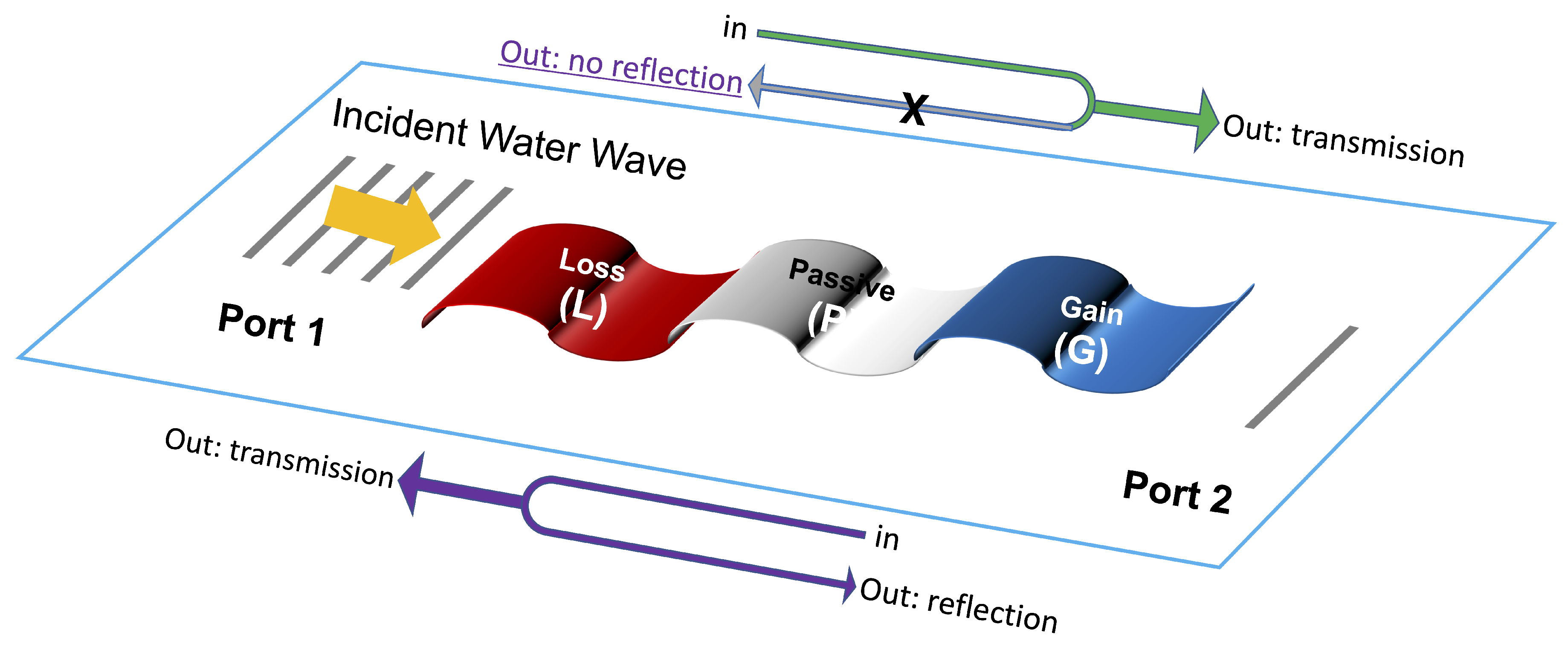
The structures considered in this work are thin elastic plates floating atop water, as schematized in Figure 1. The thickness of the plate is assumed to be very small in comparison to its lateral dimension L and the FG wavelength, i.e., and . Also, we assume that the depth of water h is small in comparison to wavelength, i.e., the shallow water approximation, i.e., . Furthermore, it is assumed that the flow of water is irrotational, thus the velocity field can be expressed as , with the scalar velocity potential. The water elevation in the plate’s region is denoted W. From the shallow water equation, we have
In the plate’s region, we can express the relationship between the liquid elevation and pressure exerted by the thin-plate using the linearized Bernoulli equation, i.e.,
where g is the surface gravity of Earth and the mass density of water. Last, the pressure exerted by the plate can also be expressed by the dynamic condition, as
where the Laplacian is understood as operating in the 2D space, i.e., in the x-y-plane of the plate and the mean free surface of water. Moreover, M is the surface density of the plate (i.e., mass per unit of surface) and D its flexural rigidity, i.e., , with E the Young’s modulus of the plate and its Poisson’s ratio. By combining Equations (1)–(3), we can derive the equation obeyed by the velocity potential in its domain of validity, in case of isotropic and homogeneous physical parameters, i.e., D, h, M, and ,
The second term of this equation can be safely ignored, as with our set of approximations, this term is much smaller than the remaining terms of the LHS of Equation (4). Thus, the equation satisfied in the plate’s region is
In the frequency domain, when we assume that (assuming a time-dependence ), we can obtain
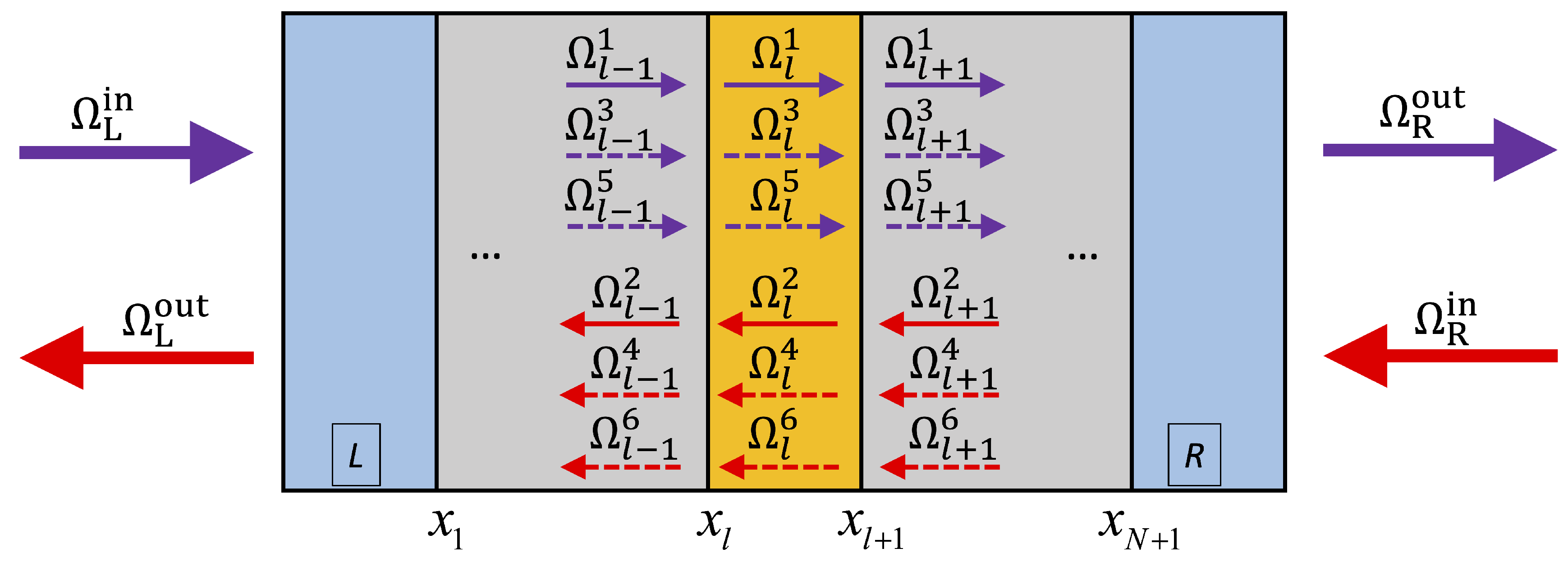
Equation (6) leads to the dispersion relation (by replacing the Laplacian by , with the FG wavenumber) . In order to solve Equation (6) we need to supply the boundary conditions, which in the case of a plate-plate boundary, consist of ensuring the continuity of the six parameters , , , , , and , corresponding to the six unknowns (See Figure 2) [44,45], with n the normal to the boundary and s the tangential coordinate, i.e.,
and
where the operator . For a plate-water boundary, we have instead four boundary conditions that are a continuity of and and [44]. In the case of a layered-structure as the one shown in Figure 2 these conditions simplify greatly as shown in the following.
2.2. Transfer and Scattering Matrix Formalism for Flexural-Gravity Waves
Equation (6) governs the scattering and propagation of FG waves in the buoyant plate region. However, another wave system should be considered here, which is linearized LSW waves, in the incidence and transmission regions (regions denoted L and R, respectively in Figure 2). In these regions the waves are governed by the usual Helmholtz equation, i.e., , with . To the best of our knowledge, the TMM and SMM for this coupled system have never been studied before. Here, we are going to give detailed derivation and analysis of these matrices.
2.2.1. Transfer Matrix Formalism
The transfer matrix corresponding to the layer l (See Figure 2) relates the vector to , as , through the continuity conditions at the interface . This consists of finding the propagator of these FG waves. Therefore, we define the set of matrices at the coordinates and
and
with the normalized propagation constants solution of Equation (6). Here, is the FG wavenumber in layer l and the coefficient . This shows that the governing PDE of flexural-gravity waves possesses one propagating component and two evanescent components in each direction, as schematized in Figure 2.
Thus we have the following relations
Hence, it is straightforward to derive
where the associated transfer matrix of layer l is . If we have N layers, we must first take the product of all these matrices, i.e., .
The next step is to relate the unknowns (i.e., coefficients and ) through the transfer matrix. In fact, we have and . Therefore
Thus, in the same way, we can get the overall transfer matrix of the multilayered structure, i.e.,
This matrix is and is obviously different from transfer matrices in electromagnetics and acoustics, which are . The main difference is the existence of two kinds of evanescent waves, localized only at the interfaces between layers, in addition to the usual propagating one.
2.2.2. Scattering Matrix Formalism
Up to here, the derivation is classical and is similar to other wave systems, e.g., flexural waves in TEPs [46]. Usually, at this point, to obtain the S-matrix, we have to re-write Equation (11), in order to obtain the incoming coefficient and the outgoing ones, at different sides of the equation, and the proportionality matrix of the scattering one. Yet, here, this is not possible, as the coefficients in Equation (11) are those of FG waves, but the S-matrix should be expressed in terms of LSW coefficients, as schematized in Figure 2 (). However, the trick consists of relating the outer coefficients to the inner ones ; thus we can reduce the number of unknowns from 12 to 6. In addition to these, we must add the reflection and transmission coefficient from the water-wave region. For instance, without loss of generality, we can consider that the waves are normally incident from the left side, with a normal amplitude, that is , , , and , with r and t the reflection and transmission coefficients, respectively. Since we have eight boundary conditions at the interfaces (left-side) and (right-side) (four for each interface, given in Section 2.1), our problem is perfectly defined. By applying these conditions, we end up with the specific linear system, function of the coefficients t, r, and , that is
with the terms elements of the transfer matrix, given in Equation (12). The sums in the first four lines, just express the relation between the coefficients of the outer layer as function of those of the inner layer, through Equation (11). Hence, it is straightforward, to use Equation (13) to calculate the complex coefficients t and r using the Cramer’s rules. For instance, for t we need to replace the first column by the vector in the RHS, whereas for r we replace the second column by the same vector, and divide the determinant of the obtained matrix by the determinant of the matrix in the LHS of Equation (13).
The complex transmission and reflection coefficients are computed unequivocally from Equation (13). These coefficients are then used to define the scattering matrix (in terms of only propagating waves), i.e.,
where we denote by and the reflection coefficient from the right and the left side, respectively (i.e., right or left incidence, respectively). The S-matrix given here satisfies the relation , where is the complex conjugate operator. Hence, it can be concluded that . The eigenvalues of this coupled scattering system () are obtained as functions of ( and ), i.e., , with .
3. Results
In Equation (6), we choose to add loss/gain to the flexural rigidity D, as for the density, it is more difficult and less common, as well as the height of the plate h and the acceleration due to gravity g that appear as coefficients in Equation (6), these should be real-valued. The parity () and time () operators are as usual in the frameworks of acoustics/optics. By balancing the gain and the loss in D, i.e., by enforcing , one can obtain the parity-time symmetric subsequent effects. As D is proportional to the Young’s modulus E, this means we need both gain and loss in E. Hence, the structure which we consider, as schematized in Figure 1, consists of three uniform elastic floating layers with perfect contact conditions at their interfaces, denoted as G, P, and L, which stand for gain, passive, and loss, respectively. The passive layer here acts as a coupling layer between the gain and loss layers. The possible realization of gain and loss in such elastic structures has been already proposed in Refs. [34,47]. A shunted piezoelectric TEP [35,36] may lead to an effective Young’s modulus that possesses a positive (gain) or negative (loss) imaginary part, depending on the use of an inductor and a positive (negative) resistor. We assume that the gain and/or loss can be tuned in a reasonable range, and consider a structure, consisting of gain/passive/loss layers, illustrated in the inset of Figure 3b. As we seek some applications in maritime engineering, the width of these layers (in the x-direction) is assumed to be identical and is set as 30 m. The thickness of the plate (in the z-direction) is a constant for all layers and is assumed to be 1 m. The other parameters of the plate are taken as follows: density, (to make it floating atop water), Poisson’s ratio, 0.334, and real part of the Young’s modulus, 1.1 GPa, which corresponds to materials used in floating mega-structures.
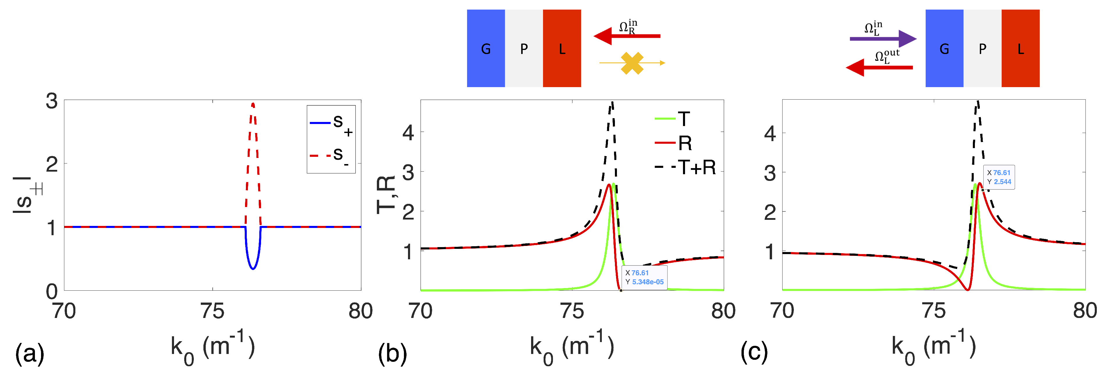
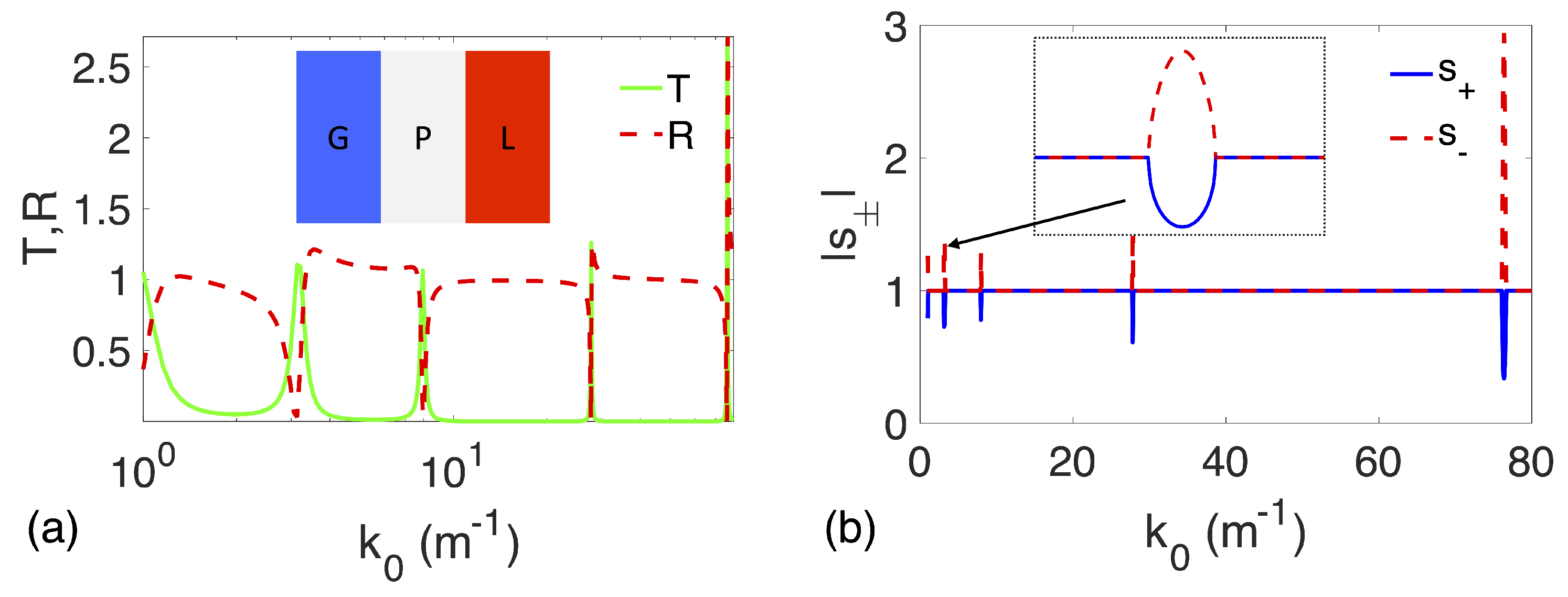
Using the SMM given by Equation (13), we compute the reflection and transmission spectra of this structure when a unit-amplitude plane LSW wave is impinging from the left and/or the right, as shown in Figure 1. The results are depicted in Figure 3 in the wavenumber range 70–80 . Since -symmetric wave systems are reciprocal, it is verified that the transmittance is the same for wave incident from both directions, as can be seen in Figure 3b,c. However, for this specific -symmetric scenario, the reflectance is drastically different for the right () and left () incidences as shown in Figure 3b,c. For instance, at wavenumber which is an extreme amplification (resonant effect) of the incident wave, whereas (). At the wavenumber , we observe however the opposite behavior, i.e., resonant reflection for the right incidence and zero-reflection for the left incidence, as well as the Fano line-shape for the reflection spectrum [48], but in a mirror symmetric fashion, by comparing Figure 3b,c. The broadband operation is depicted for the wavenumber range 0.1–80 (which corresponds to a broadband LSW wavelengths in the surrounding medium, assuming the more general dispersion relation for LSW. For instance, similar results can also be obtained for smaller wavenumbers and wider plates.) in Figure 4. For instance, Figure 4a shows the transmission/reflection spectra with the characteristic Fano line-shape for several regions (zones), while Figure 4b gives the eigenvalues (in absolute values) [46,49], showing several EPs, with various strengths. We use the following definition for the EP: the location whence the transmittance is unitary () and one of the reflectance coefficients is zero () [50,51]. Each of these EPs results from broken -symmetry [See inset of Figure 4b].
4. Discussion: CPAL Effect
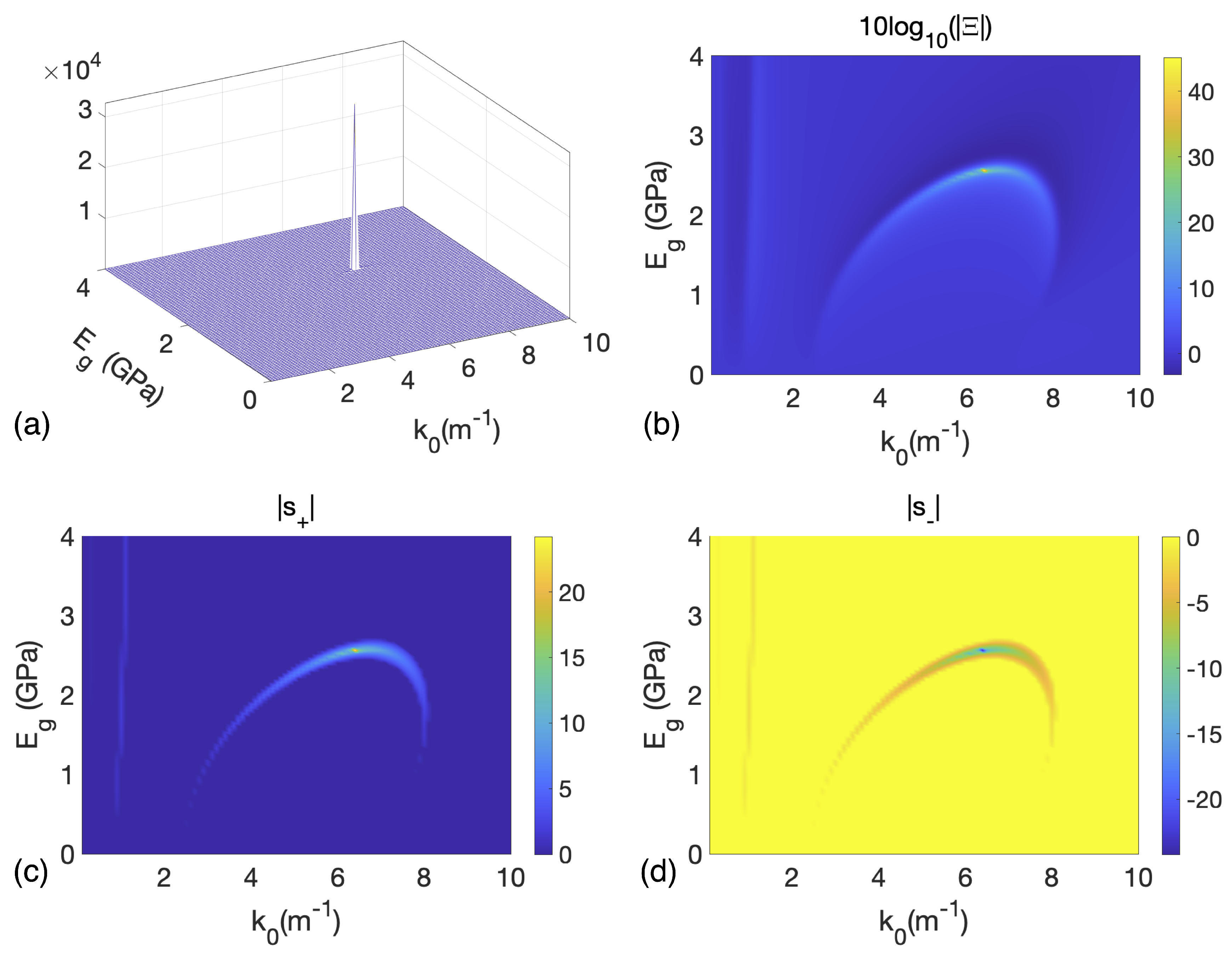
In the previous sections, we have shown that -symmetry breaking resulting in EPs can be generalized to the peculiar situation of coupled LSW and FG waves. This observation is somehow intriguing as the system we considered couples two physically different waves, and the higher order PDE governing its propagation results in the existence of propagating and two evanescent wave solutions. In this vein, an interesting phenomenon that was previously observed for optics, electronics [49,52,53,54,55], and recently in flexural waves [46], is the CPAL effect reminiscent of singular scattering. We analyze in this section possible realizations in the realm of FG waves. For instance, we keep the same structure as previously discussed, i.e., same materials and geometrical parameters (i.e., as in Figure 1), and increase the gain/loss amplitude. The results are summarized in Figure 5. For instance, Figure 5a,b plot the output coefficient,
versus and (). From Figure 5a, we can clearly distinguish a narrow spatial region where diverges. Figure 5b is the 2D plot of Figure 5a, and the bright yellow dot stands for extreme amplification [shown in logarithmic scale, in the order of ), in terms of scattered (reflected and transmitted) energy normalized by the incident energy]. In the considered scenario, this CPAL can be obtained for and GPa.
Figure 5c,d give the variation of the eigenvalues versus the same parameters. From these figures, we see that undergo at the same location CPAL effect. For instance diverges while vanishes and thus correspond to lasing, perfect absorption, respectively. Realizing such CPAL devices for LSW waves may lead to some interesting applications, especially in ocean wave harvesting, where we could imagine building a structure based on our device that (nearly) fully absorbs water waves and then convert it to electricity. The lasing can lead to similar applications, where the transmitted wave is much higher than the incident one; another device can be used to harvest this signal.
5. Conclusions
The scattering of flexural-gravity waves propagating in layered buoyant thin-plates was analytically studied by means of the transfer matrix and scattering matrix formalism, and was subsequently analyzed. We make use of recent proposals [47] suggesting that the use of externally shunted circuits, with positive and negative resistances, permits to obtain gain and/or loss in beams and TEPs, alike. With this intriguing property, we analytically investigate, for the first time, the existence and tunability of EPs for such elastic structures (thin-plates), and show that the well-known behavior of unidirectional reflectionless photonic and phononic devices can be similarly observed for flexural-gravity waves in TEPs. The spontaneous breaking of -symmetry was observed in the frequency domain and shown to lead to CPAL effect for LSW. This design complements what has been done for beams or for negative refraction in plates. It also shows that despite the existence of evanescent waves (localized at the interfaces), both robust -symmetry and EP take place. This can pave the way to several interesting applications, as flexural-gravity waves in TEPs are gaining increasing interest, e.g., in density sensing, early detection of tsunamis, filtering [56], trapping [57] of ocean waves, and vibration control of mechanical systems.
Author Contributions
Conceptualization, M.F. and Y.W.; methodology, M.F.; formal analysis, M.F., S.G., P.-Y.C. and Y.W.; investigation, M.F., S.G., P.-Y.C. and Y.W.; resources, Y.W.; writing—original draft preparation, M.F.; writing—review and editing, M.F., S.G., P.-Y.C. and Y.W.; supervision, Y.W.; funding acquisition, Y.W. All authors have read and agreed to the published version of the manuscript.
Funding
This research was funded by King Abdullah University of Science and Technology (KAUST) Office of Sponsored Research (OSR) under Grant No. OSR-2016-CRG5-2950 and KAUST Baseline Research Fund BAS/1/1626-01-01.
Conflicts of Interest
The authors declare no conflict of interest. The funders had no role in the design of the study; in the collection, analyses, or interpretation of data; in the writing of the manuscript, or in the decision to publish the results.
References
- Kadic, M.; Bückmann, T.; Schittny, R.; Wegener, M. Metamaterials beyond electromagnetism. Rep. Prog. Phys. 2013, 76, 126501. [Google Scholar] [CrossRef]
- Papanicolaou, G. Wave Propagation in Complex Media; Springer Science & Business Media: Berlin, Germany, 2012; Volume 96. [Google Scholar]
- Pendry, J.B.; Holden, A.; Stewart, W.; Youngs, I. Extremely low frequency plasmons in metallic mesostructures. Phys. Rev. Lett. 1996, 76, 4773. [Google Scholar] [CrossRef] [Green Version]
- Kadic, M.; Bückmann, T.; Schittny, R.; Wegener, M. Experiments on cloaking in optics, thermodynamics and mechanics. Philos. Trans. R. Soc. Math. Phys. Eng. Sci. 2015, 373, 20140357. [Google Scholar] [CrossRef] [Green Version]
- Leonhardt, U. Optical conformal mapping. Science 2006, 312, 1777–1780. [Google Scholar] [CrossRef]
- Pendry, J.B.; Schurig, D.; Smith, D.R. Controlling electromagnetic fields. Science 2006, 312, 1780–1782. [Google Scholar] [CrossRef] [Green Version]
- Zolla, F.; Guenneau, S.; Nicolet, A.; Pendry, J. Electromagnetic analysis of cylindrical invisibility cloaks and the mirage effect. Opt. Lett. 2007, 32, 1069–1071. [Google Scholar] [CrossRef]
- Cai, W.; Chettiar, U.K.; Kildishev, A.V.; Shalaev, V.M. Optical cloaking with metamaterials. Nat. Photonics 2007, 1, 224. [Google Scholar] [CrossRef] [Green Version]
- Ergin, T.; Stenger, N.; Brenner, P.; Pendry, J.B.; Wegener, M. Three-dimensional invisibility cloak at optical wavelengths. Science 2010, 328, 337–339. [Google Scholar] [CrossRef] [Green Version]
- Farhat, M.; Chen, P.Y.; Guenneau, S.; Enoch, S. Transformation Wave Physics: Electromagnetics, Elastodynamics, and Thermodynamics; CRC Press: Boca Raton, FL, USA, 2016. [Google Scholar]
- Pendry, J.B. Negative refraction makes a perfect lens. Phys. Rev. Lett. 2000, 85, 3966. [Google Scholar] [CrossRef]
- Smith, D.R.; Pendry, J.B.; Wiltshire, M.C. Metamaterials and negative refractive index. Science 2004, 305, 788–792. [Google Scholar] [CrossRef] [Green Version]
- Alù, A.; Engheta, N. Achieving transparency with plasmonic and metamaterial coatings. Phys. Rev. E 2005, 72, 016623. [Google Scholar] [CrossRef] [Green Version]
- Chen, P.Y.; Soric, J.; Alu, A. Invisibility and cloaking based on scattering cancellation. Adv. Mater. 2012, 24, OP281–OP304. [Google Scholar] [CrossRef]
- Farhat, M.; Chen, P.Y.; Guenneau, S.; Enoch, S.; Alu, A. Frequency-selective surface acoustic invisibility for three-dimensional immersed objects. Phys. Rev. B 2012, 86, 174303. [Google Scholar] [CrossRef] [Green Version]
- Kasap, S.O. Principles of Electronic Materials and Devices; McGraw-Hill: New York, NY, USA, 2006; Volume 2. [Google Scholar]
- Yablonovitch, E. Photonic crystals: Semiconductors of light. Sci. Am. 2001, 285, 46–55. [Google Scholar] [CrossRef]
- Khelif, A.; Aoubiza, B.; Mohammadi, S.; Adibi, A.; Laude, V. Complete band gaps in two-dimensional phononic crystal slabs. Phys. Rev. E 2006, 74, 046610. [Google Scholar] [CrossRef] [Green Version]
- Movchan, A.; Movchan, N.; McPhedran, R. Bloch–Floquet bending waves in perforated thin plates. Proc. R. Soc. Math. Phys. Eng. Sci. 2007, 463, 2505–2518. [Google Scholar] [CrossRef]
- Wu, Y.; Lai, Y.; Zhang, Z.Q. Elastic metamaterials with simultaneously negative effective shear modulus and mass density. Phys. Rev. Lett. 2011, 107, 105506. [Google Scholar] [CrossRef]
- Kadic, M.; Bückmann, T.; Stenger, N.; Thiel, M.; Wegener, M. On the practicability of pentamode mechanical metamaterials. Appl. Phys. Lett. 2012, 100, 191901. [Google Scholar] [CrossRef] [Green Version]
- Timoshenko, S.P.; Woinowsky-Krieger, S. Theory of Plates and Shells; McGraw-Hill: New York, NY, USA, 1959. [Google Scholar]
- Brûlé, S.; Enoch, S.; Guenneau, S. Emergence of seismic metamaterials: Current state and future perspectives. Phys. Lett. A 2020, 384, 126034. [Google Scholar] [CrossRef]
- Ungar, E.E.; Sturz, D.H.; Amick, C.H. Vibration control design of high technology facilities. Sound Vib. 1990, 24, 20–27. [Google Scholar]
- Norris, A.; Vemula, C. Scattering of flexural waves on thin plates. J. Sound Vib. 1995, 181, 115–125. [Google Scholar] [CrossRef]
- Graff, K.F. Wave Motion in Elastic Solids; Courier Corporation: North Chelmsford, MA, USA, 2012. [Google Scholar]
- Farhat, M.; Chen, P.Y.; Bağcı, H.; Enoch, S.; Guenneau, S.; Alu, A. Platonic scattering cancellation for bending waves in a thin plate. Sci. Rep. 2014, 4, 4644. [Google Scholar] [CrossRef] [PubMed] [Green Version]
- Farhat, M.; Guenneau, S.; Enoch, S. Ultrabroadband elastic cloaking in thin plates. Phys. Rev. Lett. 2009, 103, 024301. [Google Scholar] [CrossRef]
- Zhu, J.; Liu, Y.; Liang, Z.; Chen, T.; Li, J. Elastic waves in curved space: Mimicking a wormhole. Phys. Rev. Lett. 2018, 121, 234301. [Google Scholar] [CrossRef]
- Dubois, M.; Farhat, M.; Bossy, E.; Enoch, S.; Guenneau, S.; Sebbah, P. Flat lens for pulse focusing of elastic waves in thin plates. Appl. Phys. Lett. 2013, 103, 071915. [Google Scholar] [CrossRef] [Green Version]
- Farhat, M.; Chen, P.Y.; Guenneau, S.; Salama, K.N.; Bağcı, H. Localized surface plate modes via flexural Mie resonances. Phys. Rev. B 2017, 95, 174201. [Google Scholar] [CrossRef] [Green Version]
- Haslinger, S.; Movchan, N.; Movchan, A.; Jones, I.; Craster, R. Controlling flexural waves in semi-infinite platonic crystals with resonator-type scatterers. Q. J. Mech. Appl. Math. 2017, 70, 216–247. [Google Scholar] [CrossRef]
- McPhedran, R.; Movchan, A.; Movchan, N.; Brun, M.; Smith, M. ‘Parabolic’ trapped modes and steered Dirac cones in platonic crystals. Proc. R. Soc. Math. Phys. Eng. Sci. 2015, 471, 20140746. [Google Scholar] [CrossRef] [Green Version]
- Hou, Z.; Assouar, B. Tunable elastic parity-time symmetric structure based on the shunted piezoelectric materials. J. Appl. Phys. 2018, 123, 085101. [Google Scholar] [CrossRef] [Green Version]
- Vasseur, J.; Hladky-Hennion, A.C.; Djafari-Rouhani, B.; Duval, F.; Dubus, B.; Pennec, Y.; Deymier, P.A. Waveguiding in two-dimensional piezoelectric phononic crystal plates. J. Appl. Phys. 2007, 101, 114904. [Google Scholar] [CrossRef]
- Hladky-Hennion, A.C.; Decarpigny, J.N. Finite element modeling of active periodic structures: Application to 1–3 piezocomposites. J. Acoust. Soc. Am. 1993, 94, 621–635. [Google Scholar] [CrossRef]
- Rüter, C.E.; Makris, K.G.; El-Ganainy, R.; Christodoulides, D.N.; Segev, M.; Kip, D. Observation of parity–time symmetry in optics. Nat. Phys. 2010, 6, 192. [Google Scholar] [CrossRef] [Green Version]
- Christensen, J.; Willatzen, M.; Velasco, V.; Lu, M.H. Parity-time synthetic phononic media. Phys. Rev. Lett. 2016, 116, 207601. [Google Scholar] [CrossRef] [PubMed] [Green Version]
- Shi, C.; Dubois, M.; Chen, Y.; Cheng, L.; Ramezani, H.; Wang, Y.; Zhang, X. Accessing the exceptional points of parity-time symmetric acoustics. Nat. Commun. 2016, 7, 1–5. [Google Scholar] [CrossRef] [PubMed] [Green Version]
- Feng, L.; El-Ganainy, R.; Ge, L. Non-Hermitian photonics based on parity–time symmetry. Nat. Photonics 2017, 11, 752. [Google Scholar] [CrossRef]
- Li, H.X.; Rosendo-López, M.; Zhu, Y.F.; Fan, X.D.; Torrent, D.; Liang, B.; Cheng, J.C.; Christensen, J. Ultrathin acoustic parity-time symmetric metasurface cloak. Research 2019, 2019, 8345683. [Google Scholar] [CrossRef] [Green Version]
- Wu, Q.; Chen, Y.; Huang, G. Asymmetric scattering of flexural waves in a parity-time symmetric metamaterial beam. J. Acoust. Soc. Am. 2019, 146, 850–862. [Google Scholar] [CrossRef] [Green Version]
- Fleury, R.; Sounas, D.; Alu, A. An invisible acoustic sensor based on parity-time symmetry. Nat. Commun. 2015, 6, 5905. [Google Scholar] [CrossRef]
- Zilman, G.; Miloh, T. Hydroelastic buoyant circular plate in shallow water: A closed form solution. Appl. Ocean. Res. 2000, 22, 191–198. [Google Scholar] [CrossRef]
- Farhat, M.; Chen, P.Y.; Bagci, H.; Salama, K.N.; Alù, A.; Guenneau, S. Scattering theory and cancellation of gravity-flexural waves of floating plates. Phys. Rev. B 2020, 101, 014307. [Google Scholar] [CrossRef] [Green Version]
- Farhat, M.; Chen, P.; Guenneau, S.; Wu, Y. CPA-Lasing in Thin-Elastic Plates via Exceptional Points. arXiv 2020, arXiv:2007.01674. [Google Scholar]
- Hou, Z.; Ni, H.; Assouar, B. P T-Symmetry for Elastic Negative Refraction. Phys. Rev. Appl. 2018, 10, 044071. [Google Scholar] [CrossRef]
- Amin, M.; Elayouch, A.; Farhat, M.; Addouche, M.; Khelif, A.; Bağcı, H. Acoustically induced transparency using Fano resonant periodic arrays. J. Appl. Phys. 2015, 118, 164901. [Google Scholar] [CrossRef] [Green Version]
- Farhat, M.; Yang, M.; Ye, Z.; Chen, P.Y. PT-Symmetric Absorber-Laser Enables Electromagnetic Sensors with Unprecedented Sensitivity. ACS Photonics 2020, 7, 2080–2088. [Google Scholar] [CrossRef]
- Lin, Z.; Ramezani, H.; Eichelkraut, T.; Kottos, T.; Cao, H.; Christodoulides, D.N. Unidirectional invisibility induced by P T-symmetric periodic structures. Phys. Rev. Lett. 2011, 106, 213901. [Google Scholar] [CrossRef] [PubMed] [Green Version]
- Ge, L.; Chong, Y.; Stone, A.D. Conservation relations and anisotropic transmission resonances in one-dimensional PT-symmetric photonic heterostructures. Phys. Rev. A 2012, 85, 023802. [Google Scholar] [CrossRef] [Green Version]
- Chong, Y.; Ge, L.; Stone, A.D. P t-symmetry breaking and laser-absorber modes in optical scattering systems. Phys. Rev. Lett. 2011, 106, 093902. [Google Scholar] [CrossRef] [Green Version]
- Feng, L.; Wong, Z.J.; Ma, R.M.; Wang, Y.; Zhang, X. Single-mode laser by parity-time symmetry breaking. Science 2014, 346, 972–975. [Google Scholar] [CrossRef]
- Zhang, J.; Peng, B.; Özdemir, Ş.K.; Pichler, K.; Krimer, D.O.; Zhao, G.; Nori, F.; Liu, Y.X.; Rotter, S.; Yang, L. A phonon laser operating at an exceptional point. Nat. Photonics 2018, 12, 479. [Google Scholar] [CrossRef]
- Sakhdari, M.; Estakhri, N.M.; Bagci, H.; Chen, P.Y. Low-Threshold Lasing and Coherent Perfect Absorption in Generalized P T-Symmetric Optical Structures. Phys. Rev. Appl. 2018, 10, 024030. [Google Scholar] [CrossRef] [Green Version]
- Dupont, G.; Remy, F.; Kimmoun, O.; Molin, B.; Guenneau, S.; Enoch, S. Type of dike using C-shaped vertical cylinders. Phys. Rev. B 2017, 96, 180302. [Google Scholar] [CrossRef] [Green Version]
- Bennetts, L.G.; Peter, M.A.; Craster, R.V. Graded resonator arrays for spatial frequency separation and amplification of water waves. J. Fluid Mech. 2018, 854, R4. [Google Scholar] [CrossRef] [Green Version]
Figure 1.
Structure of the gain/loss floating device. The top (bottom) arrays describe the right (left) incidence and show the nonreciprocal behavior due to -symmetry phenomena.
Figure 1.
Structure of the gain/loss floating device. The top (bottom) arrays describe the right (left) incidence and show the nonreciprocal behavior due to -symmetry phenomena.

Figure 2.
Scheme of the transfer matrix method formalism, showing the different regions of the problem, i.e., LSW regions in blue color, and floating thin-plate. Also we can see the different plane-wave expansions in the different regions, as well as the ingoing and outgoing components in each layer.

Figure 3.
(a) Frequency variation of the eigenvalues () of the system depicted in the inset, showing a breakdown of -symmetry around , for GPa. The density of the plate is everywhere to make it floating atop water and the width and thickness of all three layers is 30 m and 1 m, respectively. (b,c) give the transmittance (T) and reflectance (R) [and total scattering (T+R)] signals in the same spectral domain for right and left incidence, respectively. Asymmetric and Fano-like line-shape reflectance could be observed for the right incidence. The left incidence results in high amplification at the same frequency.

Figure 4.
Same structure as in Figure 3, but for a broader spectrum spanning frequencies 0 to 80 . Multiple resonances could be observed, with the strongest one occurring at the highest frequency, in (a). (b) shows and multiple locations for the EPs. The inset is a magnified view around one low frequency EP.

Figure 5.
Output coefficient versus and in GPa in (a) 3D and (b) 2D (logarithmic scale) showing a localized divergence, around and GPa (yellow color). Amplitude of the eigenvalues of the -system (c) and (d) versus the same parameters, showing a distorted semi-ring-like behavior.
Figure 5.
Output coefficient versus and in GPa in (a) 3D and (b) 2D (logarithmic scale) showing a localized divergence, around and GPa (yellow color). Amplitude of the eigenvalues of the -system (c) and (d) versus the same parameters, showing a distorted semi-ring-like behavior.

Publisher’s Note: MDPI stays neutral with regard to jurisdictional claims in published maps and institutional affiliations. |
© 2020 by the authors. Licensee MDPI, Basel, Switzerland. This article is an open access article distributed under the terms and conditions of the Creative Commons Attribution (CC BY) license (http://creativecommons.org/licenses/by/4.0/).
Share and Cite
MDPI and ACS Style
Farhat, M.; Guenneau, S.; Chen, P.-Y.; Wu, Y. Parity-Time Symmetry and Exceptional Points for Flexural-Gravity Waves in Buoyant Thin-Plates. Crystals 2020, 10, 1039. https://0-doi-org.brum.beds.ac.uk/10.3390/cryst10111039
AMA Style
Farhat M, Guenneau S, Chen P-Y, Wu Y. Parity-Time Symmetry and Exceptional Points for Flexural-Gravity Waves in Buoyant Thin-Plates. Crystals. 2020; 10(11):1039. https://0-doi-org.brum.beds.ac.uk/10.3390/cryst10111039
Chicago/Turabian StyleFarhat, Mohamed, Sebastien Guenneau, Pai-Yen Chen, and Ying Wu. 2020. "Parity-Time Symmetry and Exceptional Points for Flexural-Gravity Waves in Buoyant Thin-Plates" Crystals 10, no. 11: 1039. https://0-doi-org.brum.beds.ac.uk/10.3390/cryst10111039
Note that from the first issue of 2016, this journal uses article numbers instead of page numbers. See further details here.