Microstructure and Mechanical Properties of Ti-6Al-4V Fabricated by Electron Beam Melting

1
College of Mechanical and Electrical Engineering, Harbin Engineering University, Harbin 150001, China
2
College of Materials Science and Chemical Engineering, Harbin Engineering University, Harbin 150001, China
3
Aerospace Hiwing (Harbin) Titanium Industry Co., Ltd., Harbin 150001, China
*
Author to whom correspondence should be addressed.
Crystals 2020, 10(11), 972; https://0-doi-org.brum.beds.ac.uk/10.3390/cryst10110972
Submission received: 27 September 2020
/
Revised: 19 October 2020
/
Accepted: 21 October 2020
/
Published: 27 October 2020
Abstract
:Electron beam melting technique is a kind of near-net shaping, environmentally friendly metal additive manufacturing technique, which can form high-performance metal parts with complex shapes. It has been widely applied in the aerospace industry, biomedical application, automobile manufacturing, and other fields. Ti-6Al-4V is the most widely researched and applied alloy in the additive manufacturing field, but its microstructure is diverse, and its mechanical properties vary greatly. In this study, the effect of process parameters on the microstructure and the resulting mechanical properties of Ti-6Al-4V alloy was researched. The results show that the yield strength of Ti-6Al-4V alloy with a bimodal microstructure is higher than those with a basketweave microstructure. Energy dispersion spectrum (EDS) line scan and area scan results show that there is no element enrichment for the specimens with the highest yield strength. A speed factor of less than 40 is a must for obtaining relatively dense Ti-6Al-4V parts built with electron beam melting. We have done basic research for the subsequent manufacturing of complex shape parts, which is helpful to promote the application of electron beam melting technology in the aerospace field.
1. Introduction
The electron beam has the advantage of high energy density, fast scanning speed, and no mechanical inertia. Electron beam melting technology (EBM) developed by Arcam is a metal additive manufacturing technology based on the scatter-accumulation principle, employing an electron beam as the energy source. This technology can produce components with high precision and complex shape as well as excellent properties, which has broad application prospects in the aerospace industry, biomedical application, and automobile manufacturing [1,2,3,4].
The Ti-6Al-4V alloy is the most widely researched and applied material due to its high specific strength, fatigue strength, and corrosion resistance. A significant amount of research has been carried out on the microstructure and mechanical properties of Ti-6Al-4V alloy formed by electron beam melting technology. In general, the microstructure of EBM Ti-6Al-4V alloys is diversified and the mechanical properties vary greatly. Fine needle-like α phase separated by the β phase was found to exist in EBM Ti-6Al-4V parts [5,6,7,8], while fine lamellar α/β dual-phase microstructure was a typical microstructure of EBM parts [4,9,10]. Sinan et al. [8] found martensite in the top area of the samples with heights of 2 and 5 mm, but the martensite in the top area of the samples with a height of 18 mm was not obvious. Tan et al. [11] found that α′ martensitic existed in the Ti-6Al-4V specimen. Lu et al. [12] reported a variety of patch-shaped massive grains in the EBM Ti-6Al-4V sample and the massive grains consisted of ultrafine lamellar α and β phases. Razavi et al. [2] reported that equiaxed α grains were observed in the evaluated Ti-6Al-4V samples. Columnar prior β-grains were found to grow through multiple layers and their major axis oriented along the build direction for EBM parts [2,13,14].
As for yield strength, Zhai et al. [15] had reported that the yield strength of EBM Ti-6Al-4V in the Q10 horizontal condition was 973 MPa, while in Q10 vertical condition the yield strength was 1051 MPa. Murr et al. [16] claimed that the yield strength of EBM Ti-6Al-4V was as high as 1150 MPa. Sepe et al. [1] reported that the yield strength of Ti-6Al-4V was 863 MPa. Wysocki et al. [17] found that the yield strength of Ti-6Al-4V was 845 MPa. Chastand et al. [18] claimed that the yield strength of Ti-6Al-4V was 970 MPa. As for tensile strength, huge differences were also found in the data reported by different researchers. Murr et al. [16] reported that the tensile strength of EBM Ti-6Al-4V was 1200 MPa in their valuable work. Pirozzi et al. [19] discovered that the tensile strength of EBM Ti-6Al-4V machined specimens was 1020 MPa, which is consistent with that reported in literature [15,18,20]. Wysocki et al. [17] reported that the tensile strength of EBM Ti-6Al-4V in the longitudinal orientation was nearly 972 MPa.
Many factors affect the microstructure and mechanical properties of materials. Wang et al. [21] had studied the effects of building height on microstructure and mechanical properties of Ti-6Al-4V. Hrabe et al. [20], Tan et al. [11], and Sepe et al. [1] had researched the effects of parts thickness on microstructure and mechanical properties of Ti-6Al-4V. Pirozzi et al. [19] had researched the mechanical behavior of two sets of EBM Ti-6Al-4V specimens, namely built and machined ones, and they concluded that the specimens machined from EBMed cylindrical bars have shown higher mechanical properties than the built ones. Dharmendra et al. [10] investigated the microstructure and small-scale properties of horizontally and vertically printed EBM Ti-6Al-4V alloy rods and they found that the effect of build orientation on the local mechanical properties through a nanoindentation approach shows high hardness on the vertical sample. Bruno et al. [14] focused on build orientation concerning the X, Y, and Z axes and its effect on microstructure and mechanical performance of EBM Ti-6Al-4V parts. Hrabe et al. [20] demonstrated that vertically oriented EBM Ti-6Al-4V parts showed a 30% lower elongation compared to horizontally oriented parts. Different heat treatments were performed on Ti-6Al-4V by Galarraga et al. [22] and Raghavan et al. [5] to study the effects of heat treatments on the unique microstructure formed during the EBM fabrication process. When different heat treatment cycles are applied to EBM Ti-6Al-4V materials, the final microstructure can be tailored, and the mechanical properties can also be improved. However, there is still little research related to the post-processing heat treatment of EBM built Ti-6Al-4V other than HIP treatments. Hrabe et al. [23], Facchini et al. [24], Edwards et al. [25], and Rafi et al. [26] had researched the effects of hot isostatic pressing (HIP) on the microstructure and mechanical properties of Ti-6Al-4V. By adapting the HIP process, the fatigue strength of EBM Ti-6Al-4 V can be dramatically improved for the reason that the number of crack initiation sites within the material was significantly reduced. Further, the upgrading and optimization of the mechanical properties of as-built EBM products can also be realized due to the reduced amount of pores and un-melted substances [27].
Process parameters have a significant impact on the microstructure and mechanical properties of materials. Hrabe et al. [20] had researched the effect of energy input on microstructure and mechanical properties of Ti-6Al-4V. Juechter et al. [28] had studied the influence of process parameters on the resulting heat-affected zone and alloy composition of Ti-6Al-4V. Everhart et al. [29] demonstrated the relationship between scan length and the resulting density, microstructure, and mechanical properties of EBM-produced Ti-6Al-4V. However, there is still little research regarding the effect of process parameters on the microstructure and mechanical properties of EBM Ti-6Al-4V. In this paper, the effect of speed factor, focus offset and line offset on the microstructure and mechanical properties of EBM Ti-6Al-4V was investigated.
2. Materials and Methods
2.1. Materials and Processing Conditions
The powder for this article was gas atomized Ti-6Al-4V spherical powder provided by Aerospace Hiwing (Harbin, China) Titanium Industry Co., Ltd., which was illustrated in Figure 1 with a nominal diameter between 45 and 106 μm, an apparent density of 2.56 g/cm3, and a Hall flow rate of 23.9 s/50 g. For Arcam EBM Ti-6Al-4V powders, the Hall flow rate is 23 s/50 g, and the apparent density is 2.70 g/cm3 [30]. The powder had a content of 50% recycled and 50% new powder. It can be seen from Figure 1 that the as-received Ti-6Al-4V powders practically appear smooth, spherical, fully dense, and sometimes with a few small non-spherical powders attached to some bigger powders. Table 1 showed the chemical composition in wt.% of Ti-6Al-4V powders.
Reused powders are non-sintered powders recycled in previous builds, which are kept in the machine under vacuum atmosphere, thus these powders can be reused for the next build. The reuse of recycled powders will increase the oxygen content, affecting the corresponding microstructure and mechanical properties. Nandwana et al. [31] demonstrated that after five builds (150 h) without adding new powders, the oxygen content increased from 0.141 to 0.168 wt.%, however, still staying within specifications. Guschlbauer et.al. [3] had reported that the pure copper specimens produced using the powder with high oxygen level show cracks, whereas samples from the powder with low oxygen content are crack-free. Leung et al. [32] confirmed that excessive oxygen in the powder feedstock may cause defect formation in laser additive manufacturing. Therefore, the oxygen content of powders should be strictly controlled in the process of electron beam melting.
The building parameters (spot size, scan length, etc.) were defined by an internal algorithm of the Arcam Q20 machine (Arcam AB, Gothenburg, Sweden, software version 5.2, layer thickness 90 μm, accelerating voltage 60 kV). A stainless-steel substrate of 300 mm × 200 mm × 10 mm was used to build all the specimens. The build was started when a preheat temperature of 650 °C. All the specimens were built in one batch and no post-treatment was applied to the specimens.
2.2. Sample Location and Preparation
It is common sense that Ti-6Al-4V is a standard material supported by electron beam melting technology. When purchasing equipment and powders from Aram, process parameter databases for standard materials were also provided. For the Arcam Q20 machine (Arcam AB, Gothenburg, Sweden) when adapting standard Ti-6Al-4V material purchased from Arcam AB (Gothenburg, Sweden), a set of optimal process parameters (Speed factor of 35, focus offset of 48 mA, Line offset of 0.25 mm) was provided. However, the powders for this study were not from Arcam AB (Gothenburg, Sweden), when the optimal process parameters recommended for standard Ti-6Al-4V were adapted to build specimens, the yield strength of all specimens was extremely low. It is worthwhile to investigate the reason for this phenomenon. Further, the methods which could improve the yield strength of Ti-6Al-4V parts were highly significant. To facilitate the comparison of the results, combined with the advice of an experienced engineer from Aram, a variable-controlling approach was adopted in this study to investigate the influence of speed factor, line offset, as well as focus offset on the resulting microstructure and mechanical properties of Ti-6Al-4V materials. The factors and levels were shown in Table 2, and the process parameters used for fabricating the samples were shown in Table 3.
For sample No.1 to No.5, the line offset was kept as 0.25 mm, the speed factor was kept as 35, while the focus offset was increased from 39 to 51 mA. For sample No.6 to No.10, offset was kept as 0.25 mm, focus offset was kept as 48 mA, while the speed factor was increased from 29 to 41. For sample No.11 to No.15, the focus offset was kept as 48 mA, the speed factor was kept as 35, while the line offset was increased from 0.16 to 0.28 mm.
The position and orientation of the specimens on the build platform of the Arcam Q20 machine (Arcam AB, Gothenburg, Sweden) are shown in Figure 2. Cylindrical specimens have their longitudinal axis parallel to the build direction/Z-axis. Vertical tensile specimens were machined from the vertical cylinders (D15 × 100 mm). For each set of process parameters, three circular specimens and one rectangular specimen were built.
2.3. Characterization Methodology
2.3.1. Microstructure and Porosity Characterization
All specimens were cut with an abrasive wheel, mechanically ground (final grinding step: 5000 grit), polished with colloidal suspension (Struers 50 nm), and etched with Kroll’s reagent (a solution containing 3 mL HF, 5 mL HNO3 and 92 mL distilled water). Microstructures were characterized and analyzed using standard metallographic methods with DMI 5000M (Shenyang Changxiao Instrument Co., Ltd., Shenyang, Liaoning, China) metallographic microscope and FE-SEM SU5000 (Hitachi High Technologies corporation, Shanghai, China) high-resolution automatic field emission scanning electron microscope. The microstructural characterization was carried out using a small cubic sample (10 mm × 10 mm × 10 mm) manufactured directly on the build platform.
The measurement of porosity had been performed using the Archimedes method [33,34]. An as-built sample with a dimension of 10 mm × 10 mm × 10 mm was used, and distilled water was chosen as the fluid. All samples were cleaned in an ultrasound bath to evacuate the powder stuck on the surface before starting measurements. Each sample was measured three times by the same experimenter, and the average value was taken as the density of the sample. The measured density was then compared to the nominal density of Ti-6Al-4V (4.5 g/cm3) to estimate the relative density of the samples. For comparison, the micrographic observations method was also adopted. For each sample, one of the side surfaces was ground and polished, but not etched. Then the DMI 5000M (Shenyang Changxiao Instrument Co., Ltd., Shenyang, Liaoning, China) metallographic microscope was used to observe the polished surface of each sample with a magnification of ×50. At this magnification, a micrograph was taken with a length of 2.45 mm and a width of 1.82 mm. A total number of 22 micrographs were taken for each sample at the same magnification, to cover the entire surface. These images were obtained in similar light conditions and were binarized with the same threshold. Image processing software (Image-J, V1.8.0.112, National Institutes of Health) was used to analyze the porosity rate of the sample (ratio between the number of porosity pixels and the number total of pixels of one micrograph).
2.3.2. Microhardness
Microhardness measurements were carried out using a TMVS-1S (Future technology, Beijing, China) digital microhardness tester., with a load of 9.8 N applied for 15 s. Vertical microhardness measurements were conducted on the small cubic’s complete cross-section (10 × 10 mm2). Five measurements were taken every 1.5 mm in the vertical direction.
2.3.3. Tensile Testing
Tensile specimens were all machined in-house using a mill and lath, with a final dimension of 6 mm diameter and 30 mm gauge length. The EBM cylindrical Ti-6Al-4V specimens were subject to tensile testing, with a strain rate of 1 × 10⁻³ s−1 at ambient temperature by the use of the Instron 8862 high-precision fatigue testing machine (Instron, Boston, MA, USA). Three specimens were tested for each set of process parameters.
3. Results and Discussion
3.1. Defects of Electron Beam Melting of Ti-6Al-4V Alloy
The effect of focus offset, speed factor, and line offset on the surface morphology of EBM Ti-6Al-4V is shown in Figure 3. For samples with a focus offset from 39 to 45 mA, no pores were found at the top surface, so only the sample with a focus offset of 42 mA was shown. When taking a focus offset of 48 or 51 mA, visible pores were found at the top surface.
As for speed factor, samples with a speed factor from 29 to 35 shows no pores at the top surface, so only the sample with a speed factor of 29 was shown. When taking a speed factor higher than 38, a huge number of pores were found at the top surface. As for line offset, a sample with a line offset of 0.16 mm was shown for the reason that there is a metallic microbead on the top surface, which we show in Figure 4. Also, a small pore was found at the edge of the top surface of the sample with a line offset of 0.25 mm. No holes were found at the top surface of the other three samples, so only a sample with a line offset of 0.28 mm is shown.
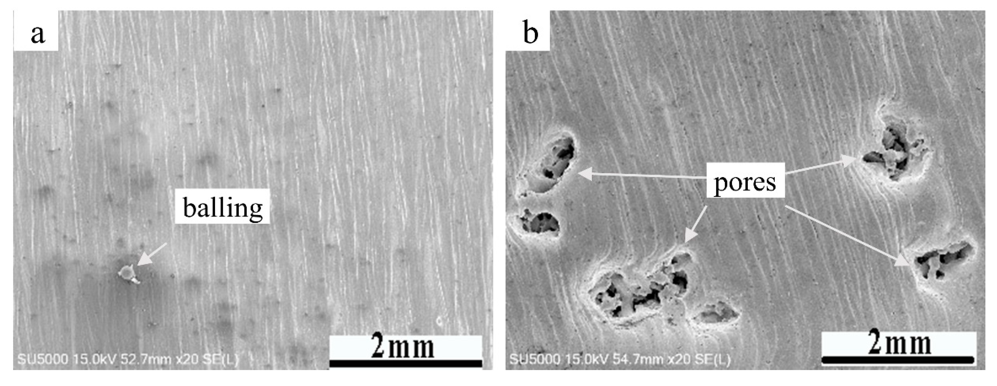
Figure 4 shows two types of defects, namely balling and pores, in EBM Ti-6Al-4V samples. In the process of building the Ti-6Al-4V specimens, a high energy electron beam was applied to the metal powder and the powders were melted to form a molten pool. When the electron beam was applied to the powder for a long time, the molten pool was continuously subjected to the impact and agitation of the electron beam, thus the molten pool produced sputtering. To reduce the free energy of the sputtering melt, spherical droplets were formed and sputtered on the solidified surface. After the droplets were solidified, metal pellets are formed, as shown in Figure 4a. Thoroughly preheating the metal powders can improve the bonding strength of the metal powder particles, to better resist the impact of an electron beam, and reduce or even eliminate the spheroidization phenomenon.
Notice that there are some pores or holes on the top surface of the Ti-6Al-4V specimens built with a speed factor of 38 or 41, and a focus offset of 48 or 51 mA. These holes seriously reduce the forming quality and have detrimental effects on the mechanical properties of the materials, so the formation of such holes should be avoided. The reason why these holes are formed is that an excessively high focus offset or speed factor was adopted to build the specimen. A higher speed factor results in higher scan speed and a bigger focus offset lead to lower energy input. Under this circumstance, the time of electron beam or energy acting on metal powders is too short to fully melt the metal powders. Therefore, these metal powders are not completely melted or even not melted, resulting in the formation of pores or holes. Hrabe et al. [20] had discovered that the range of speed factor from 30 to 40 represents the limits within which complete melting and fully dense as-built Ti-6Al-4V parts can be expected. In this article, when a speed factor of 38 is adopted, some pores are formed. This phenomenon demonstrates that to obtain fully dense Ti-6Al-4V parts, the value of the speed factor should not exceed 38. When a speed factor lower than 30 was adopted, no pores were found. Considering that a speed factor of 29 is close to 30, whether there will be holes with a smaller speed factor needs further study.
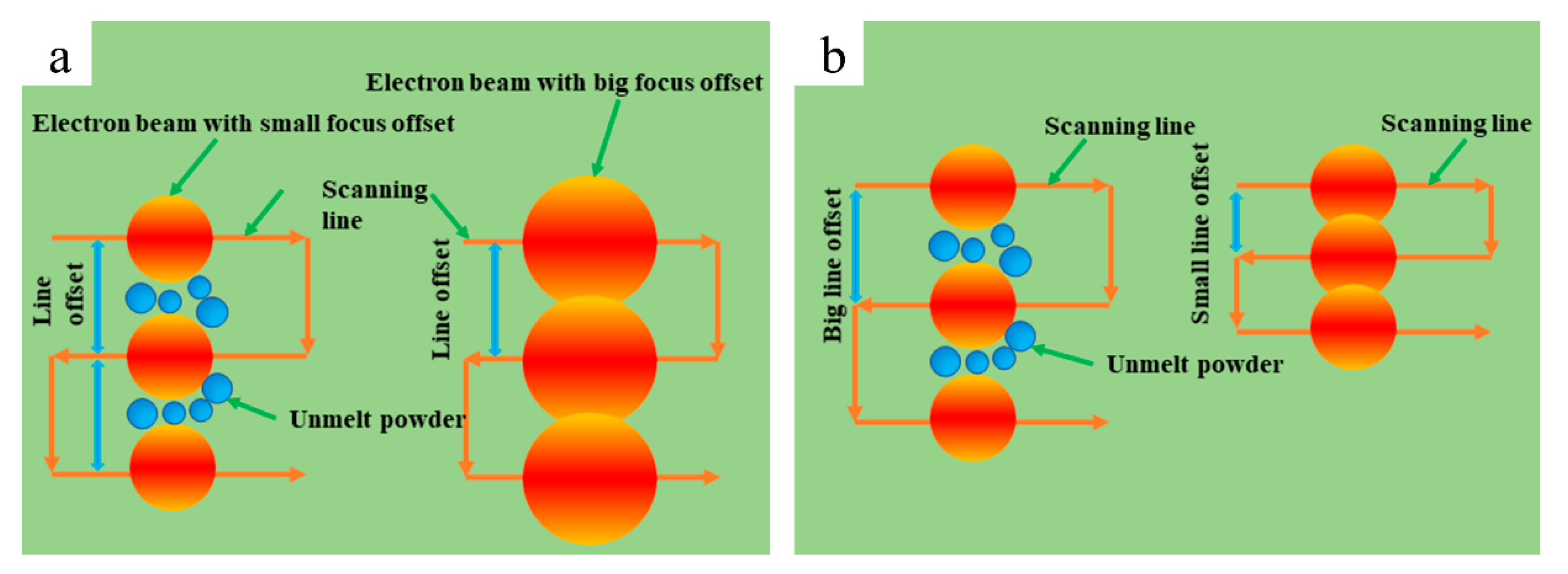
Figure 5 is a schematic diagram of the relationship between line offset and focus offset. When a large line offset but a small focus offset is adopted, the powders in some areas between two adjacent scanning lines cannot be melted by the electron beam. These powder particles are only connected by sintering necks and accumulated layer by layer, finally develop into hole defects.
Figure 6 shows the internal structure of the hole defect. During the forming process, the powders are melted when the high-energy electron beam acted on the powder. When the electron beam leaves the powder, the molten pool is rapidly cooled down and then solidified. In this process, the thermal stress generated cannot be released in time, exceeding the bearing limit of the material, resulting in the formation of thermal cracks, as shown in Figure 6a. Guschlbauer et al. [12] reported crack defects in forming copper alloys, and Chauvet et al. [13] also reported crack defects in forming nickel-based superalloys. When the electron beam acted on the powder, the powders with smaller sizes are melted first because of the rather smaller energy required. The melted small powder particles acted as a binder to bond the larger powder particles together through the sintering neck, to resist the impact of the electron beam.
Inappropriate process parameters will cause the powder to melt incompletely or even not to melt, resulting in defects such as holes and cracks, thus reducing the tensile mechanical properties of materials at ambient temperature. Therefore, appropriate process parameters should be selected during the forming process to form dense bulk parts, to obtain excellent mechanical performance.
3.2. Microstructure and Relative Density of Ti-6Al-4V Alloy Produced by Electron Beam Melting
The measured relative density of Ti-6Al-4V alloys is shown in Table 3. It can be seen from Table 3 that the maximum density is inferior to 99%, which is lower than the data reported by Galarraga et al. [35] There are two possible reasons for the lower relative density of these samples: (1) there are a small number of holes on the surface of the samples, which reduces the densification of the material; (2) in this study, the Archimedes method was used to measure the density of the samples. The results of the Archimedes method depend on the nature and temperature of the fluid, but also on the sample volume and its surface roughness [34]. However, the side surfaces of the samples built by electron beam melting were rough due to some partially melted powder particles adhered to the side surfaces, which makes the volume of the samples larger than they should be, so its density may be lower. To verify this hypothesis, the metallographic observations method was used to measure the relative density or porosity of these samples. The details of the metallographic observations are described in Section 2. Figure 7 shows the effect of different process parameters on the surface morphology of EBM Ti-6Al-4V samples after being polished. It can be seen from Figure 7 that when increasing focus offset from 39 to 51 mA, the build defects on the polished surface decrease first and then increase. The same trend was found when increasing the speed factor from 29 to 41. However, the build defects were reduced to some extent with an increasing line offset from 0.16 to 0.28 mm. Figure 8 shows the results of the measured relative density of EBM Ti-6Al-4V specimens by two methods, namely, the Archimedes method and the metallographic observations method. Surprisingly, there is a huge difference in the data obtained by different methods. For the former, the maximum relative density is less than 99%, however, a much higher relative density was gained by the latter. By using the metallographic observations method, a maximum relative density of 99.87% was gained. From Figure 8b,c, it is evident that although the measured relative density values are quite different for these two methods, the influence trend of focus offset and speed factor on relative density is almost the same, namely, when increasing focus offset or speed factor from a lower value to a higher one, the relative density increase first and then decrease.
A lower focus offset or speed factor will lead to much higher energy input, making the energy input too high. Under such conditions, the metal elements may vaporize to some degree and the recoil pressure produced by vaporization leads to the formation of pores within the molten pool, which develops into defects after solidification. When a much higher focus offset or speed factor was adopted, the energy input may too low to fully melt metal powders, thus resulting in the formation of pores. From Figure 8d, it is evident that relative density shows a different trend for these two methods. For the Archimedes method, the relative density increases first and then decreases when increasing line offset from the minimum value to the maximum one. While the relative density increases with the increase of line offset for the metallographic observation method. The mechanical performance of block parts is positively correlated with its relative density to some extent, so the influence of different process parameters on yield strength is shown in Figure 8a. When increasing speed factor or line offset from the minimum one to the maximum, the changing trend of yield strength is consistent with that of relative density for the metallographic observations method. For both methods, the changing trend of yield strength is not consistent with that of relative density when the focus offset is increasing. The reasons for the inconsistency need to be further studied. On the whole, the changing trend of relative density obtained by the metallographic observation method can better reflect the changing trend of strength. The advantages of the Archimedes method are that the whole volume is taken into consideration instead of 2D sections of the parts and that almost no destruction is made to the samples; however, this method lacks accuracy. For the metallographic observations method, it can accurately distinguish the size, number, shape as well as location of defects, which is of significant importance to investigate the effect of various defects on the mechanical properties of materials. Further, the accuracy of the metallographic observation method is higher than the Archimedes method. As a result, the metallographic observations method may be a better choice to characterize defects formed within specimens.
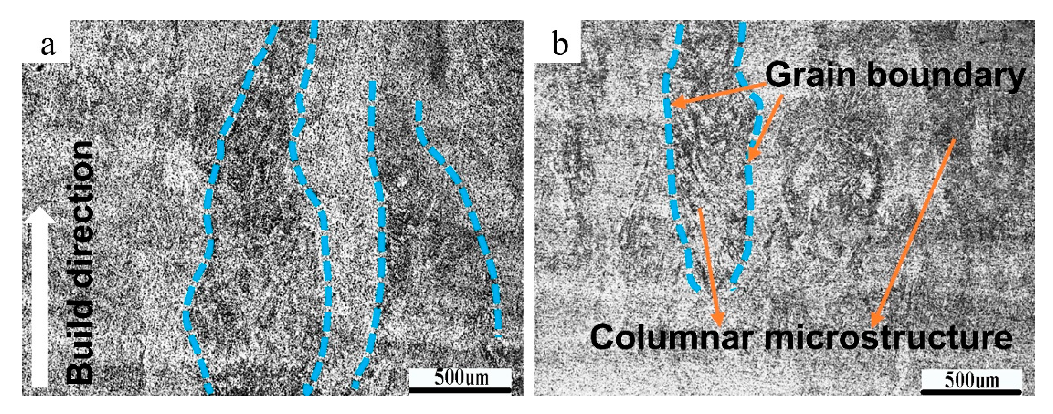
When analyzing the tensile mechanical properties of all the samples, it is found that the yield strength of the samples manufactured with a line offset of 0.16 mm is the smallest, while the yield strength of the samples formed with a line offset of 0.28 mm is the largest. Since the building direction of all the samples are along the Z-axis direction, and the tensile direction is parallel to the building direction during tensile tests, so the microstructure parallel to the building direction is studied.
Figure 9 shows the columnar crystal morphology of the samples with the lowest and highest yield strength. It can be seen that the columnar crystals grow along the building direction (the direction indicated by the white arrow), which is a typical feature of electron beam melting of metal materials. Bruno et al. [14,15,16] reported the existence of columnar crystals. Their shape is irregular, and the grain boundaries are relatively fuzzy, which are marked with cyan dot-dash lines in Figure 9a,b.
The size of the columnar crystals of the samples built with a line offset of 0.16 mm is large, but that built with a line offset of 0.28 mm is small. However, the number of columnar crystals of the latter is larger than the former. The growth direction of columnar crystals is opposite to the direction of heat flow. During the electron beam melting of Ti-6Al-4V alloy, heat conduction is mainly transferred along the building direction from the top of the samples to the bottom. The temperature gradient is the largest in the building direction. As a result, the crystal grows along the building direction. A relatively lower energy input makes the columnar crystals smaller in size.
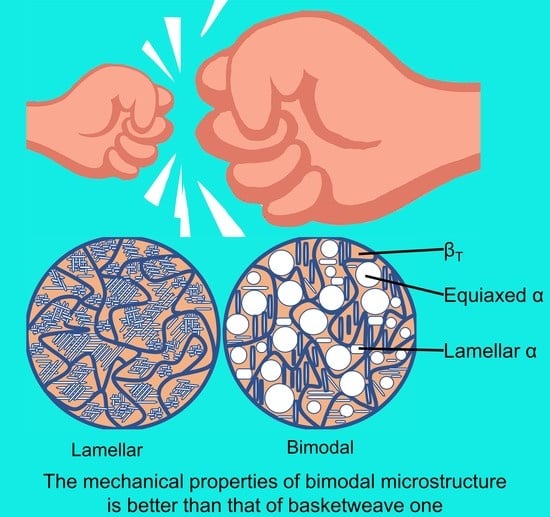
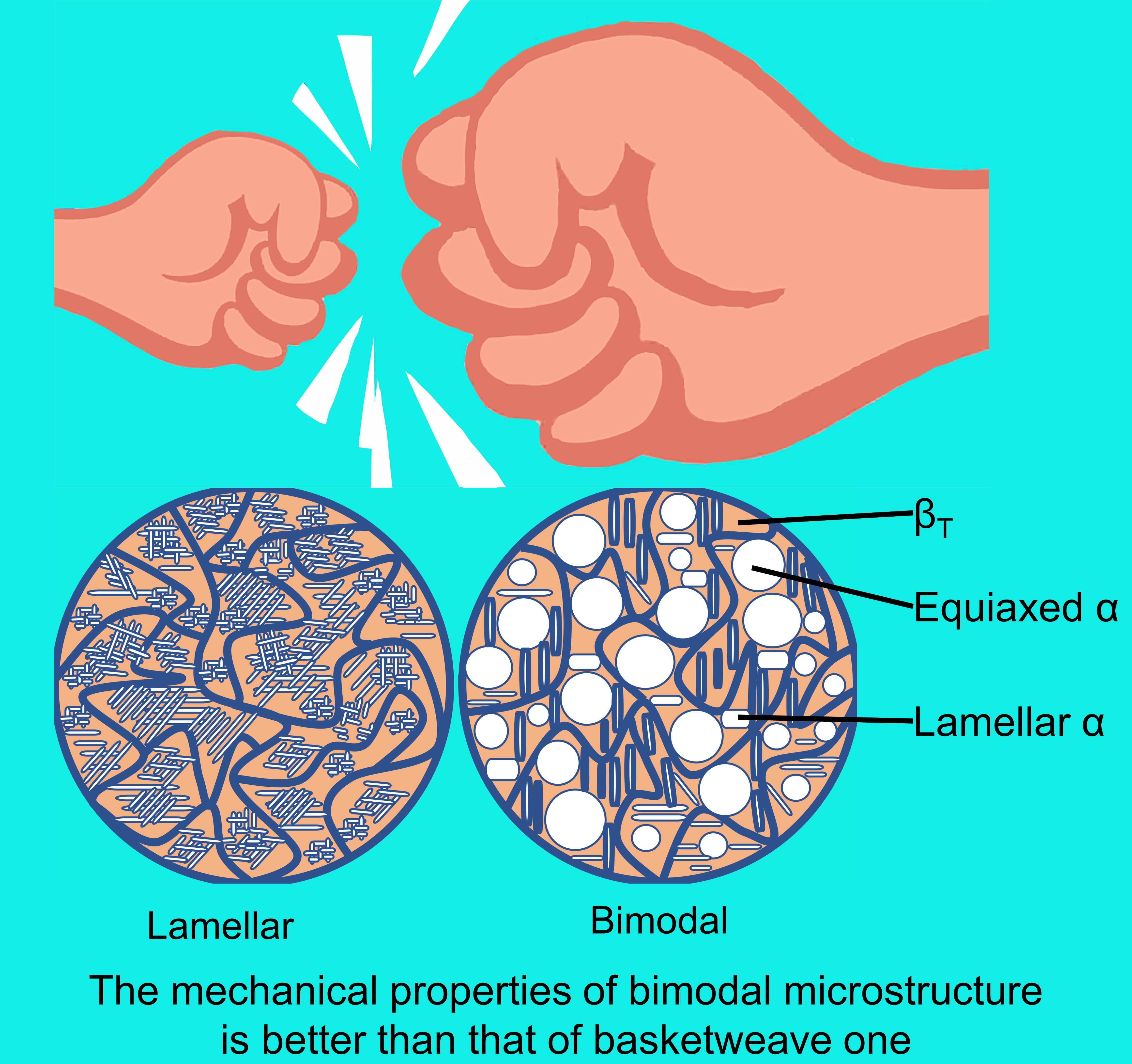
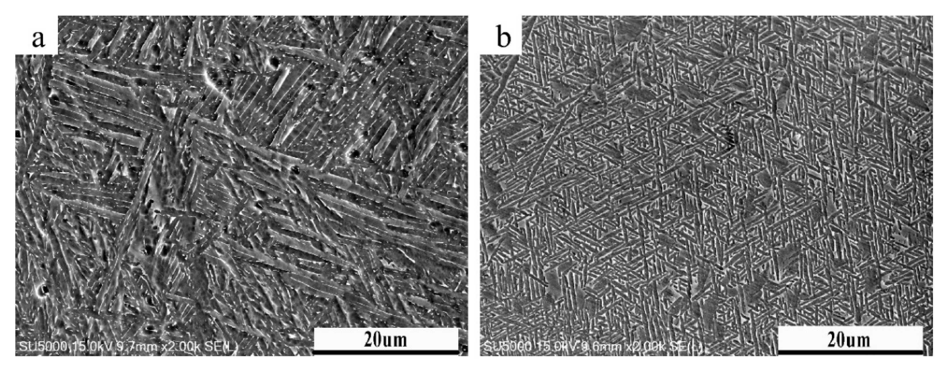
Figure 10 shows the microstructure morphology of Ti-6Al-4V alloys built with a line offset of 0.16 and 0.28 mm. It can be seen from Figure 10a that the microstructure of the former is a typical basketweave structure with elongated and needle-like α phase, and a small amount of β phase is also visible. While the microstructure of the latter is duplex. The white bright block area in Figure 10b is equiaxed primary α phase, and the elongated needle-like α phase is secondary α phase.
The microstructure of the material is closely related to its mechanical properties. Titanium alloys with duplex microstructure composed of equiaxed primary α phase and β transformed microstructure have better mechanical properties than those with basketweave microstructure [17]. The yield strength at the ambient temperature of the samples with a line offset of 0.28 mm is much higher than those of 0.16 mm, which is mutually corroborated by the microstructure observation results.
A scanning electron microscope (SEM) was used to make a further observation of the microstructure morphology of Ti-6Al-4V alloys. Figure 11 shows the morphology of Ti-6Al-4V samples with a line offset of 0.16 mm and 0.28 mm. Image-J image processing software was used to measure the average α lath thickness of the samples. The average α lath thickness of the samples with a line offset of 0.16 mm was 1.24 μm while that with a line offset of 0.28 mm was 0.53 μm. Galarraga et al. [18] had shown that materials with a smaller α lath thickness have higher strength.
In the electron beam melting process, Ti-6Al-4V powders continuously undergo a cycle of preheating–melting–cooling. When the current powder layer is melted by an electron beam, the previously solidified powder layer is remelted to a certain extent to ensure fine bonding between layers. Preheating keeps the temperature of the powder bed at about 650 °C. Under this condition, the higher the energy input is, the more energy is needed to be dissipated for the melt to cool and solidify. In the layer-by-layer deposition process, excess energy cannot be dissipated in time, which is more suitable for crystal growth, while crystal nucleation is inhibited to some extent. Therefore, the microstructure of the samples with higher energy input is coarser.
To study whether there is element segregation in grain boundaries, a line was drawn across the grain boundary, and the energy spectrum analysis was performed on the specimens with a line offset of 0.28 mm. Figure 12 shows the energy dispersion spectrum (EDS) line scan results of samples with a line offset of 0.28 mm. It can be seen that various elements are uniformly distributed throughout the scan line, and the main elements are still Ti, Al, V, C, N, and O, and that there is no element segregation in grain boundaries.
To investigate the distribution of elements on the entire surface, an EDS area scan was performed on the sample with a line offset of 0.28 mm, and the result is shown in Figure 13. It can be seen from Figure 13 that the major chemical elements on the entire scanning area are still Ti, Al, V, C, N, O, as well as a trace amount of Fe, which is consistent with the powder chemical composition test results. The elements are evenly distributed on the entire scanning area, no elements segregation or aggregation is found, which indicates that there is no composition segregation in the electron beam melting of Ti-6Al-4V titanium alloy.
3.3. Mechanical Properties at Ambient Temperature of Ti-6Al-4V Produced by Electron Beam Melting
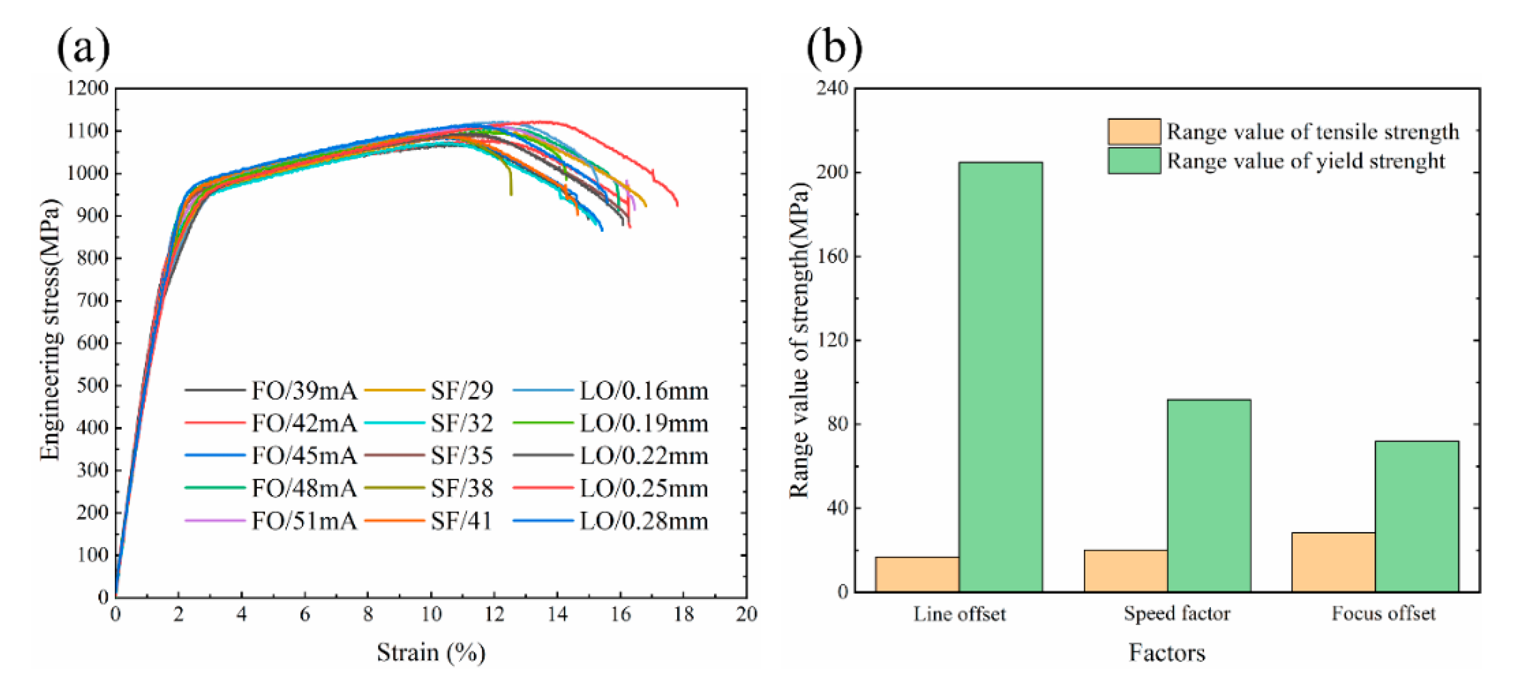
Figure 14a shows the engineering stress–strain curves of all Ti-6Al-4V samples. These curves can be divided into three areas: elastic deformation zone, uniform plastic deformation zone, and necking zone. After reaching the yield strength, these samples all have a uniform plastic deformation zone, indicating that plastic deformation requires a continuous increase of external force to continue, and that this material can prevent further plastic deformation, which reflects the strain strengthening effect of the Ti-6Al-4V alloy. The tensile specimens all have obvious necking phenomenon before fracture, and the elongation of all the specimens are higher than 10%, indicating that the Ti-6Al-4V alloys produced by electron beam melting are plastic materials.
The tensile results of all specimens are statistically analyzed to determine the factor that has the greatest impact on the ambient temperature strength of Ti-6Al-4V alloy among the three factors. It can be seen from Figure 14b that the variation of line offset, speed factor as well as focus offset have little effect on tensile strength, and the change in tensile strength is less than 30 MPa. Among the three factors, line offset has the greatest influence on the yield strength. When the line offset is increased from 0.16 to 0.28 mm, the yield strength of the sample is increased by 200 MPa.
From Table 3, it is evident that the tensile strength of EBM Ti-6Al-4V samples varies from 966 to 1000 MPa, which is consistent with the data reported by other researchers [15,17,18,20]. However, the yield strength of some samples is less than 800 MPa, lower than the data reported by other researchers [15,16,17,18], which is far from satisfactory. There are two possible reasons for the lower yield strength of Ti-6Al-4V in this paper. On the one hand, no extensometer was used during tensile tests, which may result in the measured yield strength being lower than the actual one. On the other hand, the existence of porosity would also reduce the yield strength of the materials. Porosity has a non-ignorable impact on the mechanical properties of EBM parts, especially when subjected to cyclic loads, where porosity may develop into crack nucleation, leading to premature failure of EBM parts. Porosity may result from build defects or/and powder particles containing entrapped gas. The loading direction is also important to the mechanical properties of materials in the way that when loading is applied along the build direction, build defects would have the most unfavorable effect on mechanical properties. Under this circumstance, the build direction is normal to the typically planar unmelted areas. These areas may develop into failure initiation sites, thus reduce the mechanical performance of EBM materials.
Figure 15 shows the macroscopic and microscopic fracture surface morphology of the Ti-6Al-4V samples with a line offset of 0.16 and 0.28 mm. The macroscopic fracture surfaces of these two kinds of samples both have two areas, namely a smooth area and a fiber area. The proportion of the smooth area of the former is higher than that of the latter. There are also many small holes in the fracture surfaces.
High magnification fracture morphology of the sample with a line offset of 0.16 mm shows small facets formed by cleavage fracture and a large number of dimples formed by dimple fracture. So, the fracture mode is a mixed-mode of quasi-cleavage fracture and dimple fracture. However, there are a large number of dimples in the fracture of the sample with a line offset of 0.28 mm but no small facets and steps of cleavage are visible, thus the fracture mode is transcrystalline dimple fracture. Microcracks and micropores are visible for the samples built with two different line offsets. Under the action of stress, the deformation of the interface between the α phase and β phase is inconsistent, micropores nucleate, and then grows and aggregate until the material breaks. Micropore aggregation fracture is the fracture mechanism of Ti-6Al-4V materials.
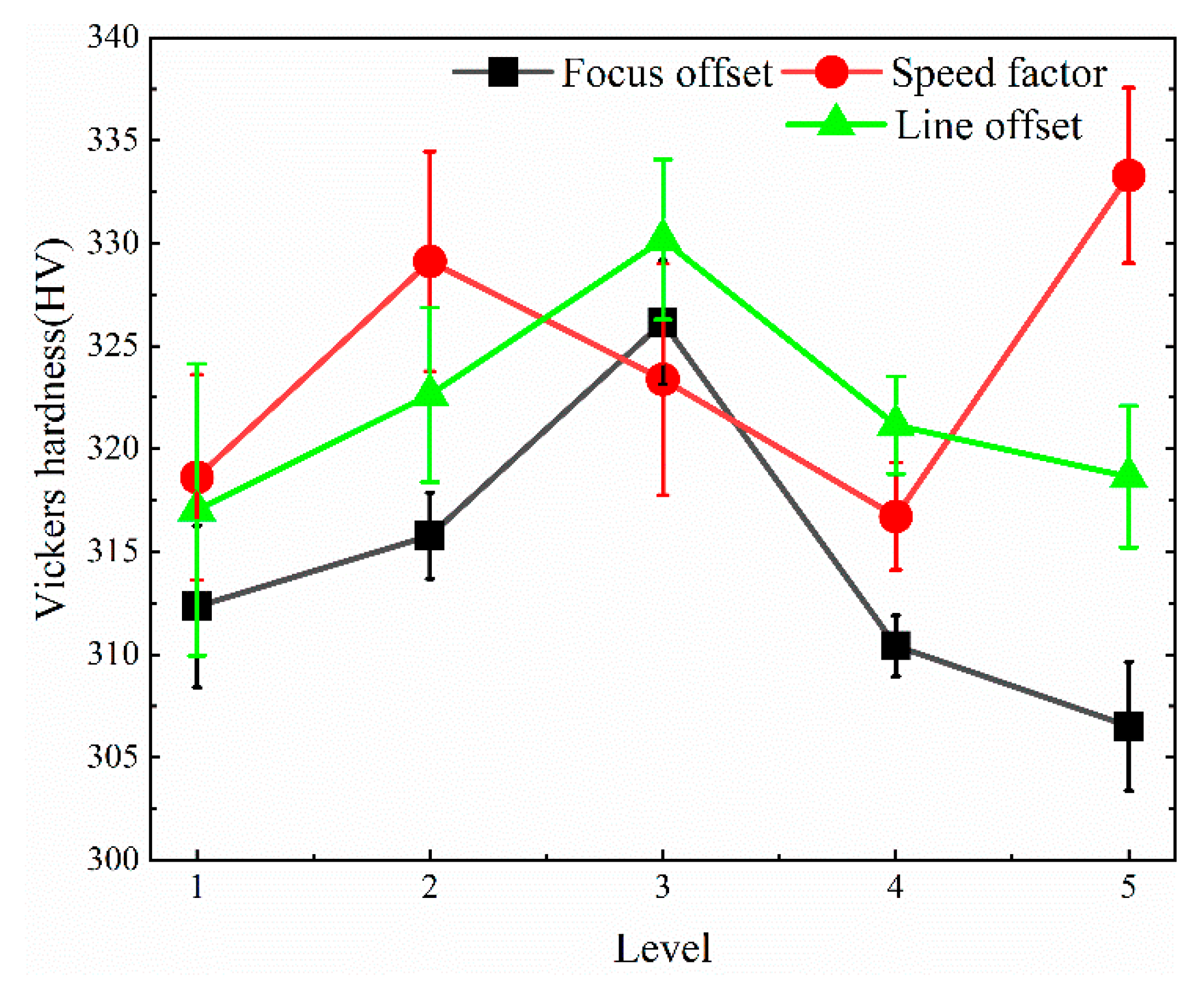
Figure 16 shows the effect of three factors on the Vickers hardness of the Ti-6Al-4V titanium alloys produced by electron beam melting. It can be seen from Figure 16 that when increasing line offset or focus offset from level 1 to level 5, Vickers hardness shows a trend of first increasing and then decreasing. The maximum value of Vickers hardness is achieved at level 3 for line offset and focus offset. Further, when the line offset takes different levels, the corresponding Vickers hardness are all higher than that of the focus offset.
As for the speed factor, the Vickers hardness shows a tendency to fluctuate as it increases from level 1 to level 5. Intuitively, the maximum value of Vickers hardness is obtained at level 5 for speed factor, however, this may be an outlier. Generally speaking, the Vickers hardness varies in the range of 300 HV–340 HV, and the variation range is of Vickers hardness is relatively small.
4. Conclusions
In this paper, three factors that affect the microstructure and mechanical properties of Ti-6Al-4V alloy produced by electron beam melting are studied, the following conclusions are preliminarily drawn:
(1) Lamellar basket-weave microstructure and bimodal microstructure can be formed within EBM Ti-6Al-4V samples depending on the process. Results of EDS line scan and area scan show that all elements are evenly distributed in the measured areas, indicating no element enrichment;
(2) In the range of process parameters studied, the change of line offset has the greatest impact on the yield strength of EBM TC4 samples. The yield strength takes its maximum and minimum value with a line offset of 0.28 and 0.16 mm, respectively. The tensile and yield strength of Ti-6Al-4V alloys with bimodal microstructure are better than those with basket-weave microstructure;
(3) To obtain relatively dense EBM Ti-6Al-4V parts, the value of the speed factor is within the range of 30–38. If the speed factor exceeds 38, pores are easy to come into being, which will reduce the yield strength of EBM Ti-6Al-4V parts. On the other hand, a speed factor lower than 30 will reduce the density of Ti-6A-4V parts, even though no pores are visible at the top surfaces;
(4) Although the process parameters vary in a wide range, there are a lot of obvious dimples on the fracture surface of tensile specimens, indicating that the fracture mode of the material is dimple fracture.
Author Contributions
Conceptualization, J.R.; methodology, X.S.; software, C.T.; validation, J.R.; formal analysis, J.R.; investigation, F.J.; resources, F.J.; data curation, J.R.; writing—original draft preparation, J.R.; writing—review and editing, H.Z.; visualization, J.R.; supervision, H.Z.; project administration, Z.C.; funding acquisition, H.Z., F.J., and Z.C. All authors have read and agreed to the published version of the manuscript.
Funding
This research was funded by the National Key R&D Program of China, grant number 2017YFB1103701; Equipment Development Department for Commission of Science and Technology, grant number 41423030504.
Acknowledgments
I would like to thank Shi-liang Wei from Harbin university of science and technology for providing many useful opinions and suggestions for the paper.
Conflicts of Interest
The authors declare no conflict of interest.
References
- Sepe, R.; Franchitti, S.; Borrelli, R.; Di Caprio, F.; Armentani, E.; Caputo, F. Correlation between real geometry and tensile mechanical behaviour for Ti6Al4V electron beam melted thin specimens. Theor. Appl. Fract. Mech. 2020, 107, 102519. [Google Scholar] [CrossRef]
- Razavi, S.; Van Hooreweder, B.; Berto, F. Effect of build thickness and geometry on quasi-static and fatigue behavior of Ti-6Al-4V produced by Electron Beam Melting. Addit. Manuf. 2020, 36, 101426. [Google Scholar] [CrossRef]
- Guschlbauer, R.; Burkhardt, A.; Fu, Z.; Körner, C. Effect of the oxygen content of the powder on the selective electron beam melting of pure copper. Mater. Sci. Eng. A 2020, 779, 139106. [Google Scholar] [CrossRef]
- Murr, L.; Quinones, S.; Gaytan, S.; Lopez, M.; Rodela, A.; Martinez, E.; Hernandez, D.; Medina, F.; Wicker, R. Microstructure and mechanical behavior of Ti–6Al–4V produced by rapid-layer manufacturing, for biomedical applications. J. Mech. Behav. Biomed. Mater. 2009, 2, 20–32. [Google Scholar] [CrossRef]
- Raghavan, S.; Nai, M.L.S.; Wang, P.; Sin, W.J.; Li, T.; Wei, J. Heat treatment of electron beam melted (EBM) Ti-6Al-4V: Microstructure to mechanical property correlations. Rapid Prototyp. J. 2018, 24, 774–783. [Google Scholar] [CrossRef]
- Neikter, M.; Åkerfeldt, P.; Pederson, R.; Antti, M.-L.; Sandell, V. Microstructural characterization and comparison of Ti-6Al-4V manufactured with different additive manufacturing processes. Mater. Charact. 2018, 143, 68–75. [Google Scholar] [CrossRef]
- Safdar, A.; Wei, L.Y.; Snis, A.; Lai, Z. Evaluation of microstructral development in electron beam melted Ti-6Al-4V. Mater. Charateriation 2012, 65, 8–15. [Google Scholar] [CrossRef]
- Al-Bermani, S.S.; Blackmore, M.L.; Zhang, W.; Todd, I. The Origin of Microstructural Diversity, Texture, and Mechanical Properties in Electron Beam Melted Ti-6Al-4V. Met. Mater. Trans. A 2010, 41, 3422–3434. [Google Scholar] [CrossRef]
- Dharmendra, C.; Alaghmandfard, R.; Hadadzadeh, A.; Amirkhiz, B.S.; Mohammadi, M. Influence of build orientation on small-scale properties of electron beam melted Ti-6Al-4V. Mater. Lett. 2020, 266, 126970. [Google Scholar] [CrossRef]
- Wang, P.; Goh, M.H.; Li, Q.; Nai, M.L.S.; Wei, J. Effect of defects and specimen size with rectangular cross-section on the tensile properties of additively manufactured components. Virtual Phys. Prototyp. 2020, 15, 251–264. [Google Scholar] [CrossRef]
- Tan, X.; Kok, Y.; Toh, W.Q.; Tan, Y.J.; Descoins, M.; Mangelinck, D.; Tor, S.B.; Leong, K.F.; Chua, C.K. Revealing martensitic transformation and alpha/beta interface evolution in electron beam melting three-dimensional-printed Ti-6Al-4V. Sci. Rep. 2016, 6, 1–10. [Google Scholar]
- Lu, S.; Qian, M.; Tang, H.; Yan, M.; Wang, J.; StJohn, D. Massive transformation in Ti–6Al–4V additively manufactured by selective electron beam melting. Acta Mater. 2016, 104, 303–311. [Google Scholar] [CrossRef]
- Ghods, S.; Schultz, E.; Wisdom, C.; Schur, R.; Pahuja, R.; Montelione, A.; Arola, D.; Ramulu, M. Electron beam additive manufacturing of Ti6Al4V: Evolution of powder morphology and part microstructure with powder reuse. Materialia 2020, 9, 100631. [Google Scholar] [CrossRef]
- Bruno, J.; Rochman, A.; Cassar, G. Effect of Build Orientation of Electron Beam Melting on Microstructure and Mechanical Properties of Ti-6Al-4V. J. Mater. Eng. Perform. 2017, 26, 692–703. [Google Scholar] [CrossRef]
- Zhai, Y.; Galarraga, H.; Lados, D.A. Microstructure, static properties, and fatigue crack growth mechanisms in Ti-6Al-4V fabricated by additive manufacturing: LENS and EBM. Eng. Fail. Anal. 2016, 69, 3–14. [Google Scholar] [CrossRef]
- Murr, L.; Esquivel, E.; Quinones, S.; Gaytan, S.; Lopez, M.; Martinez, E.; Medina, F.; Hernandez, D.; Martinez, J.; Stafford, S.; et al. Microstructures and mechanical properties of electron beam-rapid manufactured Ti–6Al–4V biomedical prototypes compared to wrought Ti–6Al–4V. Mater. Charact. 2009, 60, 96–105. [Google Scholar] [CrossRef]
- Wysocki, B.; Maj, P.; Sitek, R.; Buhagiar, J.; Kurzydłowski, K.J.; Święszkowski, W. Laser and Electron Beam Additive Manufacturing Methods of Fabricating Titanium Bone Implants. Appl. Sci. 2017, 7, 657. [Google Scholar] [CrossRef]
- Chastand, V.; Quaegebeur, P.; Maia, W.; Charkaluk, E. Comparative study of fatigue properties of Ti-6Al-4V specimens built by electron beam melting (EBM) and selective laser melting (SLM). Mater. Charact. 2018, 143, 76–81. [Google Scholar] [CrossRef]
- Pirozzi, C.; Franchitti, S.; Borrelli, R.; Caiazzo, F.; Alfieri, V.; Argenio, P. Study on the Factors Affecting the Mechanical Behavior of Electron Beam Melted Ti6Al4V. J. Mater. Eng. Perform. 2017, 26, 4491–4499. [Google Scholar] [CrossRef]
- Hrabe, N.W.; Quinn, T.P. Effects of processing on microstructure and mechanical properties of a titanium alloy (Ti–6Al–4V) fabricated using electron beam melting (EBM), Part 2: Energy input, orientation, and location. Mater. Sci. Eng. A 2013, 573, 271–277. [Google Scholar] [CrossRef]
- Wang, P.; Nai, M.L.S.; Sin, W.J.; Wei, J. Effect of Building Height on Microstructure and Mechanical Properties of Big-Sized Ti-6Al-4V Plate Fabricated by Electron Beam Melting. In Proceedings of the 4th International Conference on Material Science and Engineering Technology (ICMSET 2015), Singapore, 4 November 2015; Volume 30. [Google Scholar]
- Galarraga, H.; Warren, R.J.; Lados, D.A.; Dehoff, R.R.; Kirka, M.M.; Nandwana, P. Effects of heat treatments on microstructure and properties of Ti-6Al-4V ELI alloy fabricated by electron beam melting (EBM). Mater. Sci. Eng. A 2017, 685, 417–428. [Google Scholar] [CrossRef] [Green Version]
- Hrabe, N.; Gnäupel-Herold, T.; Quinn, T. Fatigue properties of a titanium alloy (Ti–6Al–4V) fabricated via electron beam melting (EBM): Effects of internal defects and residual stress. Int. J. Fatigue 2017, 94, 202–210. [Google Scholar] [CrossRef] [Green Version]
- Facchini, L.; Magalini, E.; Robotti, P.; Molinari, A. Microstructure and mechanical properties of Ti-6Al-4V produced by electron beam melting of pre-alloyed powders. Rapid Prototyp. J. 2009, 15, 171–178. [Google Scholar] [CrossRef]
- Edwards, P.; O’Conner, A.; Ramulu, M. Electron Beam Additive Manufacturing of Titanium Components: Properties and Performance. J. Manuf. Sci. Eng. 2013, 135, 061016. [Google Scholar] [CrossRef]
- Rafi, H.K.; Karthik, N.V.; Gong, H.; Starr, T.L.; Stucker, B.E. Microstructures and Mechanical Properties of Ti6Al4V Parts Fabricated by Selective Laser Melting and Electron Beam Melting. J. Mater. Eng. Perform. 2013, 22, 3872–3883. [Google Scholar] [CrossRef]
- Leon, A.; Levy, G.K.; Ron, T.; Shirizly, A.; Aghion, E. The effect of hot isostatic pressure on the corrosion performance of Ti-6Al-4 V produced by an electron-beam melting additive manufacturing process. Addit. Manuf. 2020, 33, 101039. [Google Scholar] [CrossRef]
- Juechter, V.; Scharowsky, T.; Singer, R.; Körner, C. Processing window and evaporation phenomena for Ti–6Al–4V produced by selective electron beam melting. Acta Mater. 2014, 76, 252–258. [Google Scholar] [CrossRef] [Green Version]
- Everhart, W.; Dinardo, J.; Barr, C. The Effect of Scan Length on the Structure and Mechanical Properties of Electron Beam-Melted Ti-6Al-4V. Met. Mater. Trans. A 2016, 48, 697–705. [Google Scholar] [CrossRef]
- Gong, H.; Rafi, K.; Gu, H.; Starr, T.L.; Stucker, B. Analysis of defect generation in Ti–6Al–4V parts made using powder bed fusion additive manufacturing processes. Addit. Manuf. 2014, 1, 87–98. [Google Scholar] [CrossRef]
- Nandwana, P.; Peter, W.H.; Dehoff, R.R.; Lowe, L.E.; Kirka, M.M.; Medina, F.; Babu, S.S. Recyclability Study on Inconel 718 and Ti-6Al-4V Powders for Use in Electron Beam Melting. Met. Mater. Trans. A 2016, 47, 754–762. [Google Scholar] [CrossRef]
- Leung, C.L.A.; Marussi, S.; Towrie, M.; Atwood, R.C.; Withers, P.J.; Lee, P.D. The effect of powder oxidation on defect formation in laser additive manufacturing. Acta Mater. 2019, 166, 294–305. [Google Scholar] [CrossRef] [Green Version]
- Spierings, A.; Schneider, M.; Eggenberger, R. Comparison of density measurement techniques for additive manufactured metallic parts. Rapid Prototyp. J. 2011, 17, 380–386. [Google Scholar] [CrossRef]
- De Terris, T.; Andreau, O.; Peyre, P.; Adamski, F.; Koutiri, I.; Gorny, C.; Dupuy, C. Optimization and comparison of porosity rate measurement methods of Selective Laser Melted metallic parts. Addit. Manuf. 2019, 28, 802–813. [Google Scholar] [CrossRef]
- Galarraga, H.; Lados, D.A.; Dehoff, R.R.; Kirka, M.M.; Nandwana, P. Effects of the microstructure and porosity on properties of Ti-6Al-4V ELI alloy fabricated by electron beam melting (EBM). Addit. Manuf. 2016, 10, 47–57. [Google Scholar] [CrossRef] [Green Version]
Figure 1.
SEM morphology of Ti-6Al-4V powder.

Figure 2.
An illustration showing the preparation of Ti-6Al-4V specimens: (a) the Aram Q20 machine; (b) inter structure of build chamber; (c) the layout of specimens in the build chamber; (d) geometry shape and size of tensile specimens; (e) As-built specimens and the machined ones after a fracture.

Figure 3.
Effect of various process parameters on the surface morphology of electron beam melting technology (EBM) Ti-6Al-4V specimens.
Figure 3.
Effect of various process parameters on the surface morphology of electron beam melting technology (EBM) Ti-6Al-4V specimens.

Figure 4.
Defects of Ti-6Al-4V produced by electron beam melting: (a) spheroidization; (b) pores.

Figure 5.
Schematic diagram of the relationship between line offset and electron beam spot: (a) line offset is the same but spot diameter is different; (b) spot diameter is the same but line offset is different.
Figure 5.
Schematic diagram of the relationship between line offset and electron beam spot: (a) line offset is the same but spot diameter is different; (b) spot diameter is the same but line offset is different.

Figure 6.
The internal structure of pore defects: (a) hot cracks; (b) unmelted powder, partially molten powder, and sintered neck.
Figure 6.
The internal structure of pore defects: (a) hot cracks; (b) unmelted powder, partially molten powder, and sintered neck.

Figure 7.
Effect of various process parameters on the porosity of EBM Ti-6Al-4V specimens.

Figure 8.
(a) Effect of various process parameters on the yield strength of EBM Ti-6Al-4V specimens; (b–d) effect of focus offset (b), speed factor(c), line offset (d) on relative density of EBM Ti-6Al-4V specimens.
Figure 8.
(a) Effect of various process parameters on the yield strength of EBM Ti-6Al-4V specimens; (b–d) effect of focus offset (b), speed factor(c), line offset (d) on relative density of EBM Ti-6Al-4V specimens.

Figure 9.
Effect of line offset on the columnar crystals morphology of Ti-6Al-4V alloy: (a) 0.16 mm; (b) 0.28 mm.
Figure 9.
Effect of line offset on the columnar crystals morphology of Ti-6Al-4V alloy: (a) 0.16 mm; (b) 0.28 mm.

Figure 10.
Effect of line offset on the microstructure morphology of Ti-6Al-4V alloy: (a) 0.16 mm; (b) 0.28 mm.
Figure 10.
Effect of line offset on the microstructure morphology of Ti-6Al-4V alloy: (a) 0.16 mm; (b) 0.28 mm.

Figure 11.
Scanning electron microscope (SEM) photographs of Ti-6Al-4V alloy under different line offset: (a) line offset is 0.16 mm; (b) line offset is 0.28 mm.
Figure 11.
Scanning electron microscope (SEM) photographs of Ti-6Al-4V alloy under different line offset: (a) line offset is 0.16 mm; (b) line offset is 0.28 mm.

Figure 12.
Energy dispersion spectrum (EDS) line scan analysis of the sample with a line offset of 0.28 mm.
Figure 12.
Energy dispersion spectrum (EDS) line scan analysis of the sample with a line offset of 0.28 mm.

Figure 13.
EDS area scan results of the Ti-6Al-4V sample with a line offset of 0.28 mm.

Figure 14.
Tensile mechanical properties of Ti-6Al-4V at ambient temperature: (a) influence of process parameters on strength; (b) tensile true stress–strain curve.
Figure 14.
Tensile mechanical properties of Ti-6Al-4V at ambient temperature: (a) influence of process parameters on strength; (b) tensile true stress–strain curve.

Figure 15.
The macroscopic morphology of the fracture surface of the Ti-6Al-4V samples formed at different line offset: (a–c) samples with a line offset of 0.16 mm; (d–f) samples with a line offset of 0.28 mm.
Figure 15.
The macroscopic morphology of the fracture surface of the Ti-6Al-4V samples formed at different line offset: (a–c) samples with a line offset of 0.16 mm; (d–f) samples with a line offset of 0.28 mm.

Figure 16.
Effect of various factors on the Vickers hardness of Ti-6Al-4V samples.


Table 1.
Ti-6Al-4V alloy powder chemical composition standard requirements and measured values.
| Element | Ti | Al | V | Fe | C | N | O | H | Other Each |
|---|---|---|---|---|---|---|---|---|---|
| Standard values (wt.%) | Bal | 5.5–6.75 | 3.5–4.5 | ≤0.3 | ≤0.080 | ≤0.05 | ≤0.20 | 0.015 | ≤0.10 |
| Measured values (wt.%) | Bal | 6.20 | 4.23 | 0.069 | 0.022 | 0.01 | 0.088 | 0.0044 | ≤0.10 |
Table 2.
Factors and different levels used for experimental design.
| Factors | Level 1 | Level 2 | Level 3 | Level 4 | Level 5 |
|---|---|---|---|---|---|
| Focus offset (mA) | 39 | 42 | 45 | 48 | 51 |
| Speed factor | 29 | 32 | 35 | 38 | 41 |
| Line offset (mm) | 0.16 | 0.19 | 0.22 | 0.25 | 0.28 |
Table 3.
Process parameters and properties of Ti-6Al-4V alloy produced by electron beam melting technology.
Table 3.
Process parameters and properties of Ti-6Al-4V alloy produced by electron beam melting technology.
| Sample | Focus Offset (mA) | Line Offset (mm) | Speed Factor | Relative Density (%) | UTS (MPa) | YS (MPa) | A (%) | Vickers Hardness (HV) |
|---|---|---|---|---|---|---|---|---|
| 1 | 39 | 0.25 | 35 | 98.49 | 966.3 | 753.8 | 15.5 | 312.3 |
| 2 | 42 | 0.25 | 35 | 98.55 | 970.0 | 774.2 | 15.7 | 315.8 |
| 3 | 45 | 0.25 | 35 | 98.63 | 982.6 | 782.6 | 15.6 | 326.2 |
| 4 | 48 | 0.25 | 35 | 98.19 | 990.1 | 816.0 | 16.6 | 310.4 |
| 5 | 51 | 0.25 | 35 | 97.24 | 994.7 | 825.8 | 16.2 | 306.5 |
| 6 | 48 | 0.25 | 29 | 98.06 | 981.6 | 747.7 | 15.9 | 318.6 |
| 7 | 48 | 0.25 | 32 | 98.45 | 971.3 | 739.2 | 15.9 | 329.1 |
| 8 | 48 | 0.25 | 35 | 98.69 | 980.8 | 831.1 | 16.1 | 323.4 |
| 9 | 48 | 0.25 | 38 | 97.97 | 991.4 | 762.4 | 12.0 | 316.7 |
| 10 | 48 | 0.25 | 41 | 97.28 | 987.1 | 763.9 | 12.7 | 333.3 |
| 11 | 48 | 0.16 | 35 | 97.97 | 999.7 | 666.4 | 11.5 | 317.0 |
| 12 | 48 | 0.19 | 35 | 98.40 | 984.8 | 708.4 | 13.8 | 322.6 |
| 13 | 48 | 0.22 | 35 | 98.44 | 983.4 | 687.8 | 15.7 | 330.2 |
| 14 | 48 | 0.25 | 35 | 98.33 | 989.3 | 693.8 | 16.9 | 321.2 |
| 15 | 48 | 0.28 | 35 | 98.28 | 1000.3 | 871.2 | 14.7 | 318.6 |
UTS stands for ultimate tensile strength, YS stands for yield strength at 0.2%.
Publisher’s Note: MDPI stays neutral with regard to jurisdictional claims in published maps and institutional affiliations. |
© 2020 by the authors. Licensee MDPI, Basel, Switzerland. This article is an open access article distributed under the terms and conditions of the Creative Commons Attribution (CC BY) license (http://creativecommons.org/licenses/by/4.0/).
Share and Cite
MDPI and ACS Style
Ran, J.; Jiang, F.; Sun, X.; Chen, Z.; Tian, C.; Zhao, H. Microstructure and Mechanical Properties of Ti-6Al-4V Fabricated by Electron Beam Melting. Crystals 2020, 10, 972. https://0-doi-org.brum.beds.ac.uk/10.3390/cryst10110972
AMA Style
Ran J, Jiang F, Sun X, Chen Z, Tian C, Zhao H. Microstructure and Mechanical Properties of Ti-6Al-4V Fabricated by Electron Beam Melting. Crystals. 2020; 10(11):972. https://0-doi-org.brum.beds.ac.uk/10.3390/cryst10110972
Chicago/Turabian StyleRan, Jiangtao, Fengchun Jiang, Xiaojing Sun, Zhuo Chen, Cao Tian, and Hong Zhao. 2020. "Microstructure and Mechanical Properties of Ti-6Al-4V Fabricated by Electron Beam Melting" Crystals 10, no. 11: 972. https://0-doi-org.brum.beds.ac.uk/10.3390/cryst10110972
Note that from the first issue of 2016, this journal uses article numbers instead of page numbers. See further details here.