3.1. AFM Measurements
AFM produced topographic images which providing information about the structural formation of the spherulites.
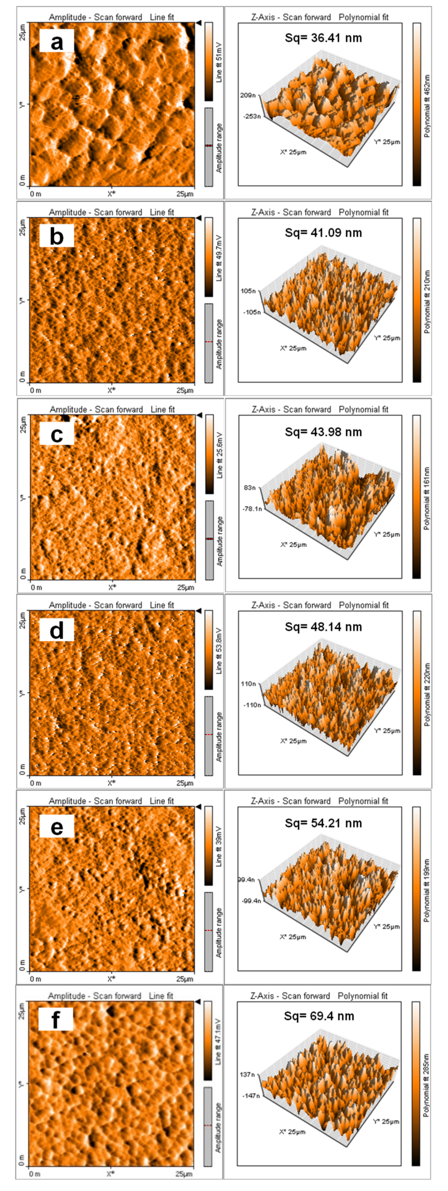
Figure 1a shows topographic image of neat P(VDF-HFP) before electron-beam irradiation. Large spherulites were presented with relatively big gaps between them. These relatively big spherulites were associated to the non-polar α-phase conformation mode that strongly affected by the film preparation technique. Ribeiro et al. have reported the effect of the different preparation methods, including solvent casting method, to the crystalline phase nucleation [
29]. In this case, the solution was casted on the glass plate by using blade and was put in the oven to evaporate the solvents. High evaporation temperature, more than 70 °C, could increase the material’s evaporation rate. So that the stability of the material is quite high, leading to α-phase crystallization [
30].
After introducing GNPs conducting nanofillers, the large gaps observed in neat P(VDF-HFP) tended to be filled with GNPs in the HFP/GN composites. Hence, a network of smaller parallel spherulites could be formed. This spherulites reduction was strongly caused by the interface reduction that occurs between each spherulites [
31]. The spherulitic microstructures of HFP/GN composites were similar to that of neat P(VDF-HFP) (
Figure 1b–f), but with smaller spherulites. This observation was consistent with a previous work reporting that adding compatible fillers in the gaps between particles of composite materials is effective to increase its cross-linking density, which is the density of a small area where parts of polymer chains are connected [
32].
GNPs demonstrated good adhesion with the polymer matrix since there were no significant gaps at the interface of GNPs and polymer. Adding a small amount of GNPs produced good dispersion and efficient electrostatic interaction preventing significant agglomeration [
33]. The strong electrostatic interaction between GNPs and polymer chains was associated with the strong dipole moment of the nanofillers and the size reduction of the spherulites [
33]. This morphological change also influenced other properties, such as the dielectric constant, which will be discussed below.
Adding GNP conducting nanofillers not only affected the spherulite size but also the surface topography of the composites, specifically the surface roughness (Sq). In neat P(VDF-HFP), the Sq value was lower because its surface comprised of a dense skin [
3]. The Sqs of all HFP/GN composites before electron-beam irradiation were higher than that of neat P(VDF-HFP). This property was associated to the full exfoliation of the GNPs, which help their dispersion in the P(VDF-HFP) copolymer matrix. Good dispersion of nanofillers in the matrix tended to generate a good interfacial strength between the nanofillers and the matrix. It was also confirmed by an prior work, which addressing a morphological change from a micro- to nano-structure and an improvement of its surface roughness [
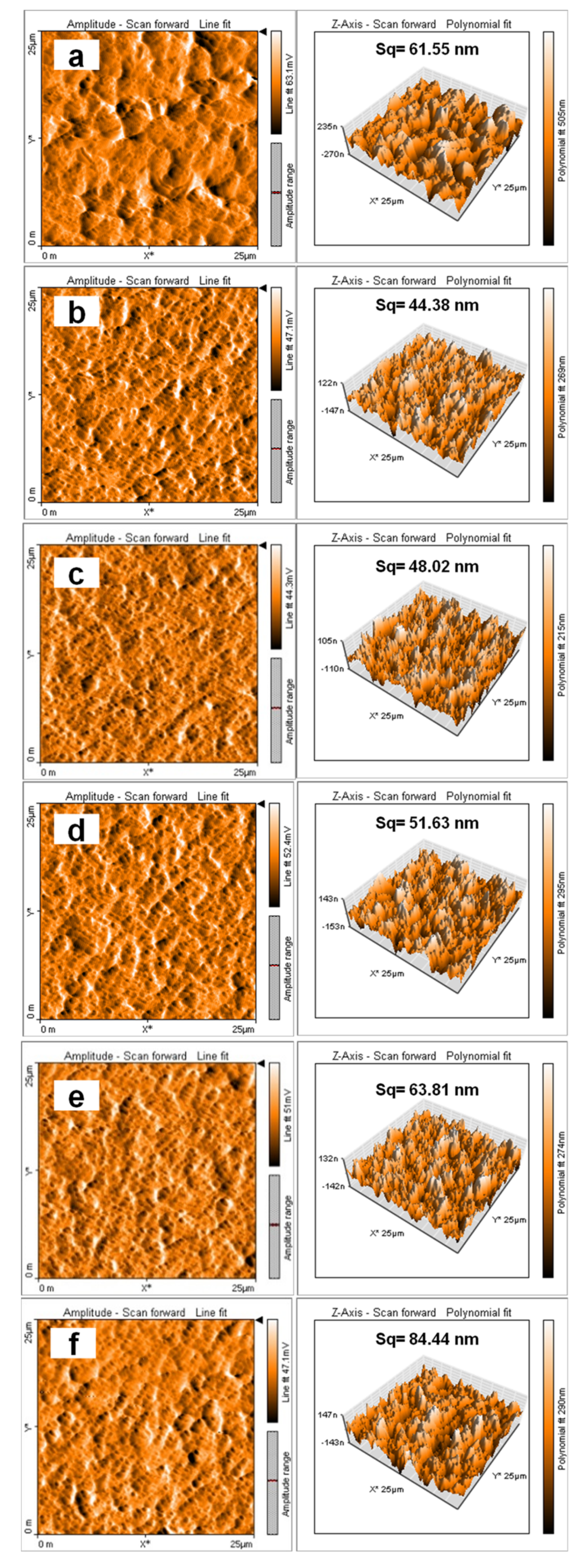
3]. After irradiation, there were no significant changes in surface topography or spherulites that observed. It shows the same trend with the AFM result before electron-beam irradiation; the spherulites of neat P(VDF-HFP) after electron-beam irradiation were also bigger than that of all HFP/GN composites (
Figure 2a–f).
Nevertheless, according to the Sq parameter, the roughness of neat P(VDF-HFP) copolymer and HFP/GN composites was increased after electron-beam irradiation. This rougher surface topography was derived from radial lamellar structures of the arrangement of the spherulites [
33] and may also be related to the electron beam’s ability to cut and break the polymer chains [
24]. This finding confirms the early work reported by Gregor et al. (2014). The creation of micro-domains after electron-beam irradiation improved the surface roughness of materials [
26].
3.2. SEM Results
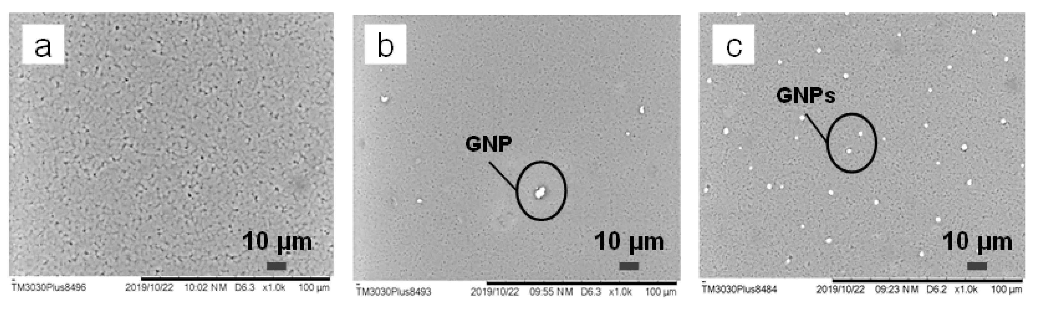
P(VDF-HFP) copolymers were dispersed in the DMF solvent (
Figure 3a). It shows that neat P(VDF-HFP) thin films with 20 wt% concentration in the solution possess a relative compact structure morphology with addition of small pores that spread out along the film. The black zones in
Figure 3a referred to the pores. The pores were ascribed from the gap that left by the DMF solvent during evaporation time. The morphology of P(VDF-HFP) was reported in a prior work that studied about the influence of concentration loading of the polymer and the evaporation temperature on P(VDF-HFP) matrix [
34]. Along with this work, the stated prior work also reported that higher concentration of P(VDF-HFP) leads to decrease the pore size of the matrix. On the other hands, a high evaporation temperature (in this case is 80 °C) can also decrease the pore size by improving the evaporation rate in DMF solvents and the polymer chain was able to occupy and fill out the space left by the DMF solvent during evaporation. As the result, this also affected the diffusion of polymers and the mobility of polymer chains [
35]. It is resulting in more compact film that separated by those small pores, along with the AFM results in
Figure 1 above, that describing the spherulitics.
Moreover, the morphology of the composites was also observed. GNPs particles were spread out within the P(VDF-HFP) matrix (
Figure 3b,c). The presence of GNPs in the P(VDF-HFP) dielectric matrix causing some properties of the matrix to change. In respect of the electrical properties, such as the dielectric constant, AC conductivity and dielectric loss, the mechanism can be analogized to the mechanism of a capacitor, where the GNPs closed to each other acts as the electrode, and the P(VDF-HFP) matrix between them as the dielectric material. Further, the composite films acted as a large group of micro-capacitors.
In
Figure 3b, there were only a few white spots indicating GNPs since the nanofiller content was only 1 wt%. However, there were more white spots in
Figure 3c since the nanofiller content was increased to 5 wt%, which imaging many micro-capacitors that formed. The comparison of
Figure 3b,c reveals that the gaps between each GNPs were much smaller at higher loading of the fillers. Thus, adding a higher percentage of GNPs conducting filler to the P(VDF-HFP) matrix could improve overall electrical properties that will be explained in the more detail below.
In addition to the spreading pattern of the filler, another factor that can be observed in
Figure 3 is the homogeneity of the matrix itself. In neat P(VDF-HFP) thin film, it can be seen clearly that the matrix (
Figure 3a) containing the pores/holes that represented by the black zones. In the opposite, the gaps or pores in the composites (
Figure 3b,c) were much smaller compared to those of the neat P(VDF-HFP). Thus, the SEM images also show the similar results and confirming the AFM results. Due to a good dispersal of the GNP nanofillers in the P(VDF-HFP) matrix, the nano-sized GNPs (0.34–100 nm) [
22] could easily fill the gaps or holes in the P(VDF-HFP) matrix and thus successfully alter its microstructure, resulting in more homogeneous and flexible films [
22]. It firmed GNPs ability as one of the most attractive materials to use in nanocomposites since they show a good dispersion performance, especially when used with a solvent. In addition to its homogeneous dispersion, GNP fillers are also well known for their affinity for radicals and excellent exfoliation in the polymer matrix.
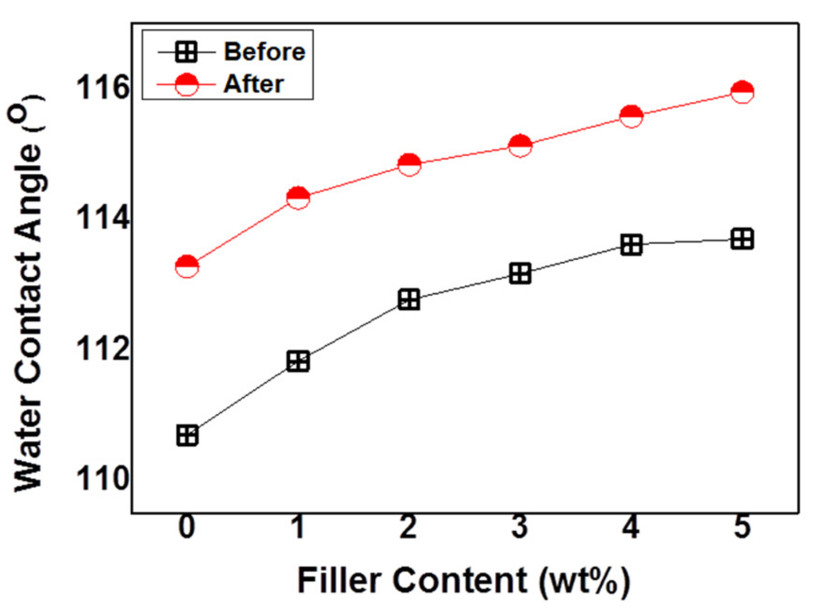
3.3. Water Contact Angle
PVDF and its copolymers are categorized as environmentally and chemically stable, hydrophobic fluorinated polymers. In simple term, hydrophobicity is a combination of two things. The first is chemical low surface energy that was defined as the measured unrealized bond energy. This is usually addressed to the molecular level of the materials. Second, the physical nano- or micro-scaled surface structure that usually quantified by surface roughness/topography measurement [
3]. The hydrophobicity of a material is usually determined by the water contact angle. There are two main ways of increasing hydrophobicity either by reducing the surface energy of a material with high surface roughness, or improving the surface roughness of a material with low surface energy.
Before irradiation, the water contact angle of neat P(VDF-HFP) that observed in this work was around 110°, much higher than that of a previously reported PVDF polymer (around 90°) [
36]. Emulsion polymerization of the HFP monomer on the PVDF polymer [
37] not only improved mechanical strength and solubility but also increased its hydrophobicity. Further, adding a small amount of GNPs to the copolymer matrix increased its water contact angle as well (
Figure 4). In simple terms, hydrophobicity is the opposite of surface energy, which depends on the type of chemical bonds created on a surface. When the more energy is required to break strong chemical bonds, such as metallic bonds, so their surface energy are also high. Then, the hydrophobicity is low. In contrast, the energy required to break weak chemical bonds, such as those in hydrocarbons, is low, so the surface energy is also low and the hydrophobicity is high.
P(VDF-HFP) is categorized as a hydrophobic material since it has weak hydrocarbon bonds. GNPs with their high density of carbon were effective at modifying the structure and producing surface roughness, as shown by the AFM results. Therefore, improving the surface roughness of hydrophobic materials with low surface energy will significantly affect the water contact angle and improve its hydrophobicity [
3]. If the surface of hydrophobic materials is roughened, the total surface area will increase so that when water drips onto such a surface, more air can be trapped on it, resulting in a higher contact angle [
3].
The water contact angle of all samples was increased after electron-beam irradiation (
Figure 4). This result confirmed those of other works that reporting the improvement of water contact angles after electron-beam irradiation [
26,
38]. Electron-beam irradiation could modify hydrophobicity by cutting chemical bonds either by chemical contamination or electron charge induction [
38]. During electron-beam irradiation, charge induction begins with the pairing of electrons with holes inside the dielectric materials. The localized states of the amorphous areas trap the weak and heavy mobile holes and the electrons can then fill the dielectric bulk much more deeply. The electrons trapped on the bulk level will generate a negative charge, while a positive charge will be generated by localized holes around the surface.
Gregor et al. (2014) suggested that hydrophobicity improvement may be associated with the creation of micro-domains [
26], in which case much higher hydrophobicity would be detected. This micro- to nano-structure change could boost hydrophobicity without any change in morphology. The creation of microdomain leads to improve surface roughness after electron-beam irradiation. Thus, higher water contact angle could be obtained through that mechanism.
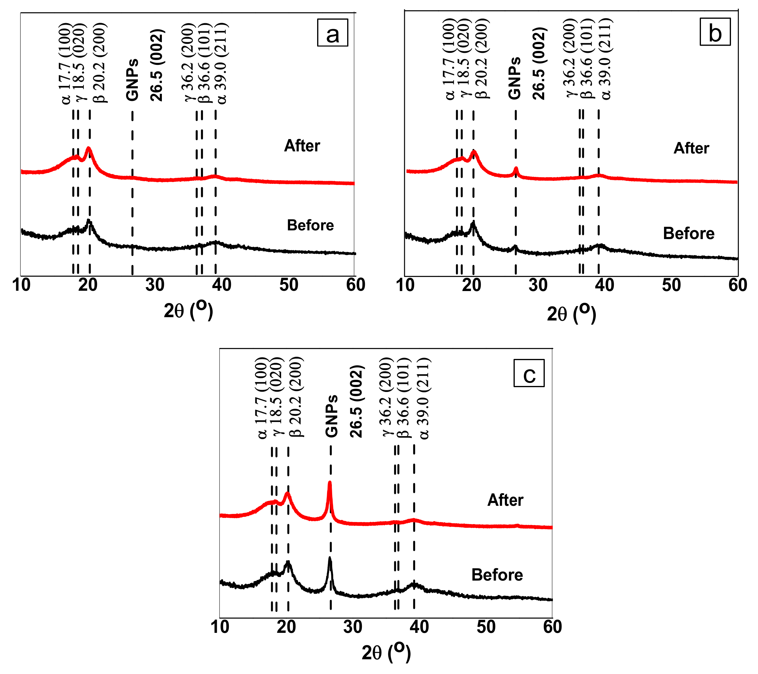
3.4. XRD Results
As a semi-crystalline material, PVDF and its composites, including P(VDF-HFP), consist of both crystalline and amorphous areas. After casting, they are well known to present a dominant α-phase whereas the crystalline phase with the most useful piezoelectrical and dielectric properties is the planar zig-zag/TTTT β-phase conformation mode [
39]. In common with this present work, many previous studies have focused on how to change the α-phase to the polar β-phase. In some cases, the two phases will only be detected in specific characteristic peaks. At those peaks, it is impossible to find other crystalline phases.
In the diffraction patterns of neat P(VDF-HFP) and HFP/GN composites before and after electron-beam irradiation, the intensity of the diffraction peak at 17.7° that associated to (100) crystallographic plane specifically corresponds to the non-polar α- and δ-phase (
Figure 5). At that peak, there is no possibility of overlapping with the γ- or β-phase. However, the intensity of these diffraction peaks in the patterns of HFP/GN composites was significantly reduced from 4755 in the neat P(VDF-HFP) to 4530. This means that adding GNP conducting nanofillers lowered the intensity of the non-polar α-phase. Physically, this α-phase intensity reduction is an indicator that introducing GNPs conducting nanofillers to the P(VDF-HFP) matrix could manipulate the crystalline phase of the polymer matrix. It was suggesting that GNPs is effective to interact with the amorphous region of the P(VDF-HFP) chains and its inter-phases [
23]. As the consequence, the P(VDF-HFP) segments diffusion could be prohibited towards the crystallization fronts.
Other non-polar α-phase diffraction peaks are found at 18.5° and 39.0°, corresponding to the (020) and (211) crystallographic planes, respectively. Along with the previous mentioned, the intensity of these characteristic α-phase peaks was also lower after adding GNPs conducting nanofillers. Moreover, the characteristic peak of the γ-phase was also detected at 18.5° and 36.2° and referred respectively to the (020) and (200) crystal planes [
40].
Interestingly, while the α-phase characteristic diffraction peaks were reduced, the polar β-phase diffraction peak intensity shows the opposite trend. The peak intensity of the β-phase at 36.6°, corresponding to the (101) crystal plane was increased from 1151 to 1225. Another observed diffraction peak that was also attributed to the polar β-phase appears at 20.2° associated to the (200) crystal plane [
23,
33]. Physically, these diffraction peak improvements of the polar β-phase ascribed to the formation of more regular and order molecules in the P(VDF-HFP) matrix that promoted by GNPs loading addition. Hence, this most electroactive polar phase formation could be generated. In addition to the change on diffraction peak intensity of polymer crystalline phases, introducing GNPs also significantly boosted up the diffraction peak at 26.5°, which was identified as the GNPs characteristic of the (002) crystal plane [
23].
Over those aforementioned above, the most significant effect was shown by electron-beam irradiation. At 39.0°, the intensity of the non-polar α-phase diffraction peak referred to (211) crystal plane was significantly reduced and even get nearly disappeared for both neat P(VDF-HFP) and HFP/GN composites. It indicates that electron beam could facilitate the more polar β-phase and stabilize it at the same time.
To confirm the XRD results, FTIR analysis was conducted. This method was very useful in determining the β-phase fraction in the material and a combination of XRD and FTIR measurements helped to determine the microstructural changes which occurred inside the material during electron-beam irradiation.
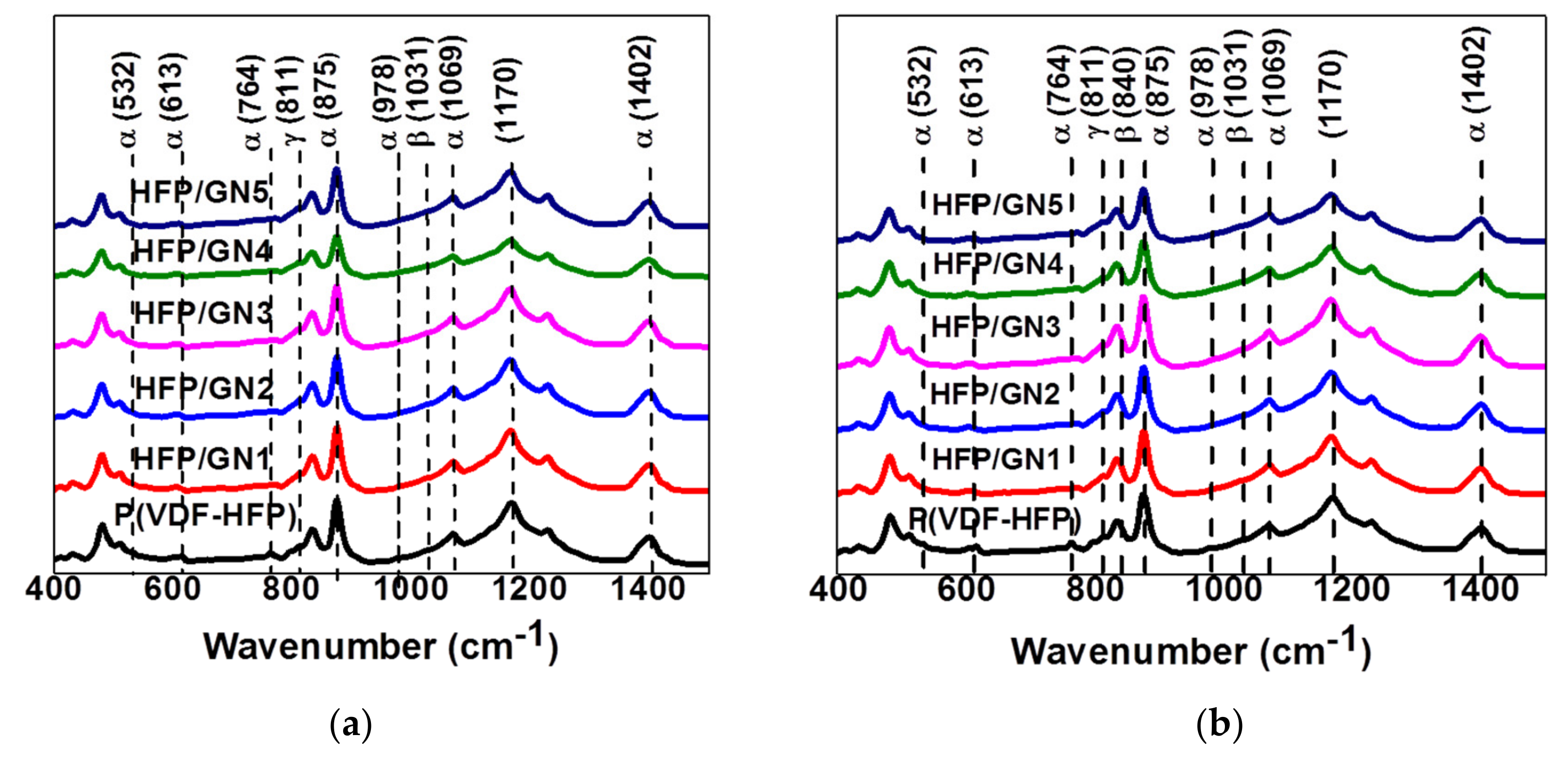
3.5. FTIR Results
Figure 6a shows the FTIR spectra of neat P(VDF-HFP) and HFP/GN composites before irradiation. The characteristic absorption peaks of the α-phase at 532, 613, 764 and 978 cm
−1 were attributed to the vibration mode of CH
2 and CF
2 groups in neat P(VDF-HFP) [
23,
33]. Peaks were also detected at 875, 1069 and 1402 cm
−1 that referred to the CF
2 stretching mode in pure P(VDF-HFP) [
39]. The peak at 875 cm
−1 is attributed to the C-C group of the α-phase in the P(VDF-HFP). Hence, at that wavenumber, it is impossible to find any other crystalline phase. However, the absorption peak at 1170 cm
−1 can be assigned to γ- and α-phases.
Absorption at peaks attributed to the α-phase was slightly decreased for HFP/GN composites. For example, the intensity of α-phase absorption peaks at wavenumber of 875, 1069 and 1402 cm
−1 in the P(VDF-HFP) were decreased from 0.71, 0.34 and 0.30 to 0.63, 0.32 and 0.27, respectively, in HFP/GN5. Further, as predicted, the reduction of α-phase absorption peaks at several wavenumbers tends to affect the intensity of the absorption peaks at 811 and 1031 cm
−1, that corresponded to γ- and β-phases, respectively. The absorption peak at 1031 itself refers to the CF
2 bending vibration modes of the β-phase [
40]. The intensity at those wavenumbers was increased slightly from 0.19 and 0.16 to 0.21 and 0.17, respectively. Those intensity changing indicates that the GNPs ability on prohibiting the non-polar α-phases as well as tailoring and transforming the most order β-phase conformation mode. Hence, these FTIR results strongly confirm and support the XRD results that firstly described.
Electron-beam irradiation also caused structural changes in the crystallinity of P(VDF-HFP) and HFP/GN composites. In the spectra of P(VDF-HFP), the α-phase absorption peaks at 875, 1069 and 1402 cm
−1 before irradiation (
Figure 6a) are reduced from 0.71, 0.34 and 0.30 to 0.54, 0.25 and 0.23, respectively, after electron-beam irradiation (
Figure 6b). Similar reductions in α-phase absorption peaks also occurred in the HFP/GN composites. The FTIR absorption data were used to calculate the crystalline fraction of the polar β-phase (
F(β)) in P(VDF-HFP) and HFP/GN composites by assuming it is in an agreement with the Lambert–Beer law expressed in the following equation:
where
Aα and
Aβ are the absorbance at wavenumber of 764 cm
−1 and 840 cm
−1, while the absorption coefficients at those wave numbers are
Kα equal to 6.1 × 10
4 cm
2 mol
−1 and
Kβ equal to 7.7 × 10
4 cm
2 mol
−1, respectively [
27].
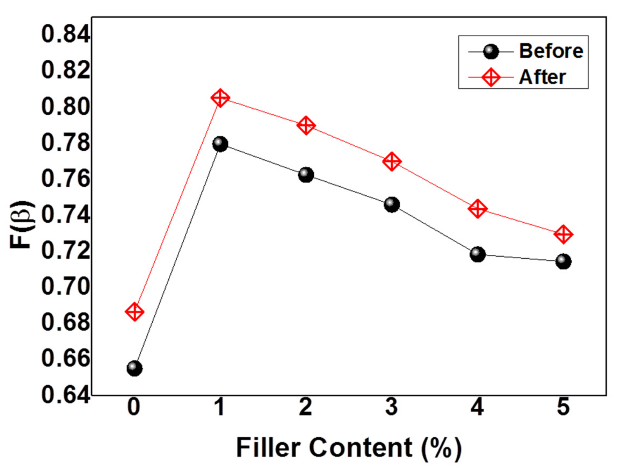
The calculated β-phase fractions (
F(β)) of all loadings before and after irradiation were shown by
Figure 7. The graph illustrates the increased β-phase content of the P(VDF-HFP) matrix after the addition of GNPs. Electron-beam irradiation was also effective in optimizing the polar β-phase. In summary, therefore, both GNPs and electron-beam irradiation promoted β-phase formation.
The increased overall β-phase content of HFP/GN was due to interfacial electrical interactions between positively charged carbon atoms in GNPs and partially negative fluorine atoms in the P(VDF-HFP), which causing a bigger dipole moment. The positively charged carbon in the GNPs tends to rotate the C–F bonds near the C–C chain backbone of the P(VDF-HFP). Hence, the β-phase could form. This result was consistent the findings of He et al. (2016) who used positive organosilicate to modify the β-phase content in PVDF [
41].
Irradiating the samples with the electron beam also affected their microstructure because the negative charge of the electron was able to interact with the positive charge of the hydrogen atoms of the P(VDF-HFP) chains. As reported in another work, interactions that occurred between the negative charge of a nanofiller and the positive charge of hydrogen, or between positively charged nanofillers and negatively charged fluorine CF
2 groups in PVDF chains generated a polar crystalline phase [
42]. In deeply, the negative charge from the electron beam will produce the local electric field in the interface of the P(VDF-HFP). This negative charge will pull the bonds that contain the opposite charges with the specific direction of the dipoles around them. Since CH
2 bonds have more positively charge than CF
2, the electron beam will rotate the CH
2 bonds resulting on more order arrangement of the dipoles. This interface interaction leads to create the β-phase nucleation.
In addition to providing data relating to changes in the crystalline phase from α- to β-phase, XRD measurements also provided useful information about crystal size. According to other studies, electron-beam irradiation could cut crystal domains into smaller sizes [
24,
28]. Through electron-beam irradiation, the width of the diffraction peaks of the neat P(VDF-HFP) and the HFP/GN composites at half-maximum gradually increased. These data could be used to control the thickness or size of crystal sheets (
D) by using the Scherrer formula [
43]:
where
K (
K = 0.89) is the Scherrer constant,
λ (
λ = 0.154 nm) is the X-ray wavelength and
B and
θ are the width of the half-maximum and the location of the diffraction peak.
Table 2 shows the crystallinity (
Xc) as well as the width of the diffraction peak of neat P(VDF-HFP) and HFP/GN composites at half-maximum (
B) and the crystal size (
D) for all conditions, before and after electron-beam irradiation. The width at half-minimum of neat P(VDF-HFP) had increased from 0.58 rad to 1.02 rad after irradiation while the crystal size had reduced from 0.60 nm to 0.48 nm. The HFP/GN composites also exhibited the same trend. For example, the width at half-minimum of HFP/GN5 had increased from 0.55 rad to 1.10 rad after electron-beam irradiation, whereas, the crystal size of the HFP/GN5 composites had decreased from 1.38 nm to 0.54 nm.
Crystal size is strongly associated with dielectric loss, which itself relates to the relaxation of the crystal domain with high polarity. In normal ferroelectrics, the β-phase is irreversible since it has a large domain/crystal size. Many researchers have investigated ways to crack or break the crystals to reduce their size and by doing so, change the loop from normal to relaxor ferroelectric, entailing a smaller dielectric loss. Larger crystals lead to a strengthening of the interaction coupling between each domain. Since the electron beam cuts the crystal into smaller domains, the interaction couplings between each domain tended to decrease [
44]. This has the advantage of enabling the dipole moment/ crystal grains to be more reversible. Hence, when the external electric field is removed, the relaxation speed of the dipole moment or crystal grains will increase and this is useful for releasing the charge stored on the material’s surface. It is for that reason that dielectric loss after electron-beam irradiation decreased along with a decrease in the crystal domain size [
43].
3.6. DSC Results
DSC measurements provided useful information about melting temperature (Tm) and melting enthalpy (ΔHm) of the films. Moreover, the degree of crystallinity (Xc) could also be calculated.
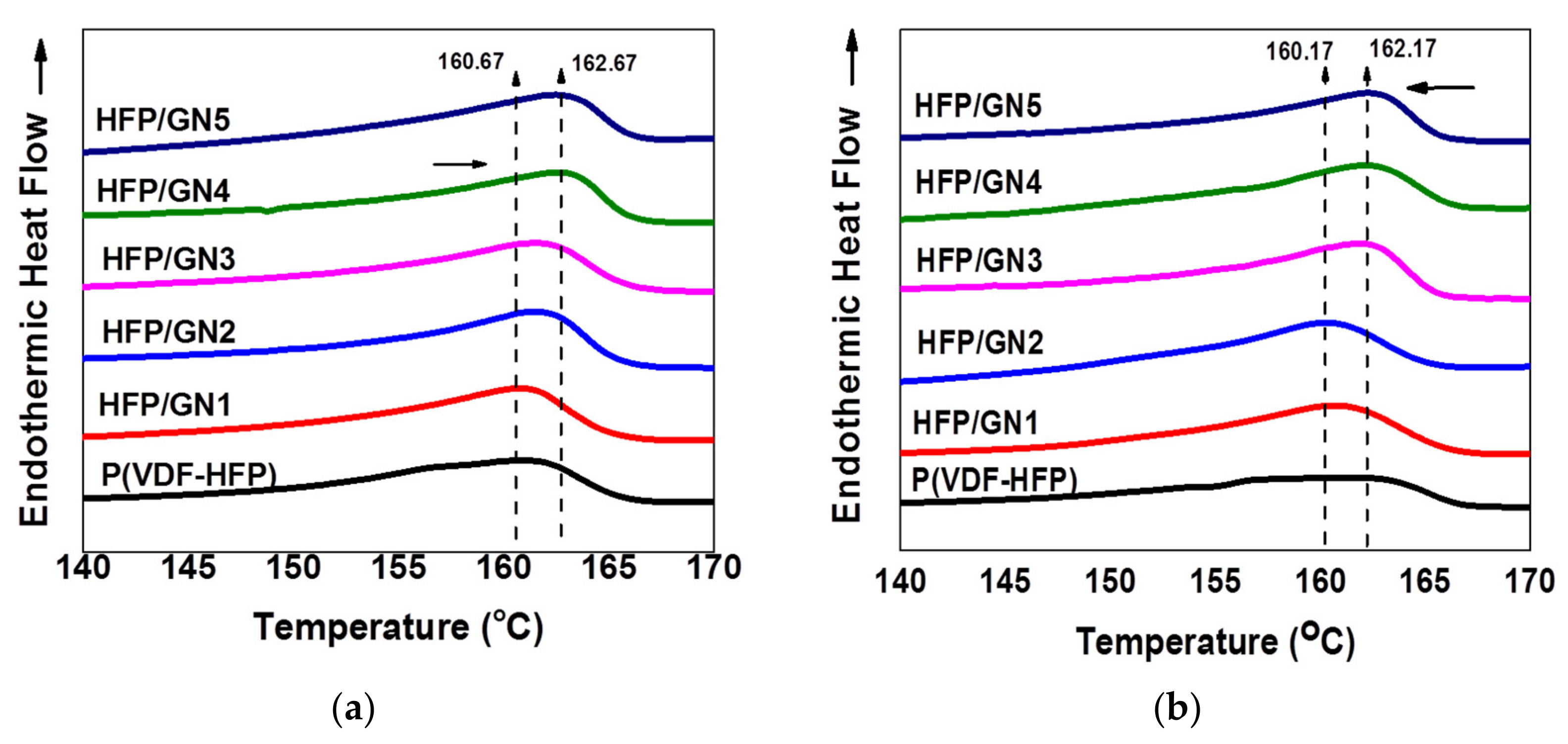
The melting temperatures (
Tm) of the HFP/GN composites were higher than that of neat P(VDF-HFP) both before and after irradiation (
Figure 8a,b). The
Tm is related to the form of the crystalline phase. The increase in melting temperature were associated with the increased β-phase formation in the films [
45] and indicated that GNPs induced the formation of the polar β-phase. Furthermore, before irradiation, the melting enthalpy (
ΔHm) of the HFP/GN composites was generally greater than that of the neat P(VDF-HFP) as was the degree of crystallinity (
Xc) (
Table 2). The
ΔHm itself is related to the nucleation of GNPs with the P(VDF-HFP) matrix [
45].
Naturally, smaller fillers such as GNPs will be dispersed more effectively than larger fillers, and the outstanding characteristics of GNPs as a reinforcing agent for polymer nanocomposites will have an impact on the polymer’s properties.
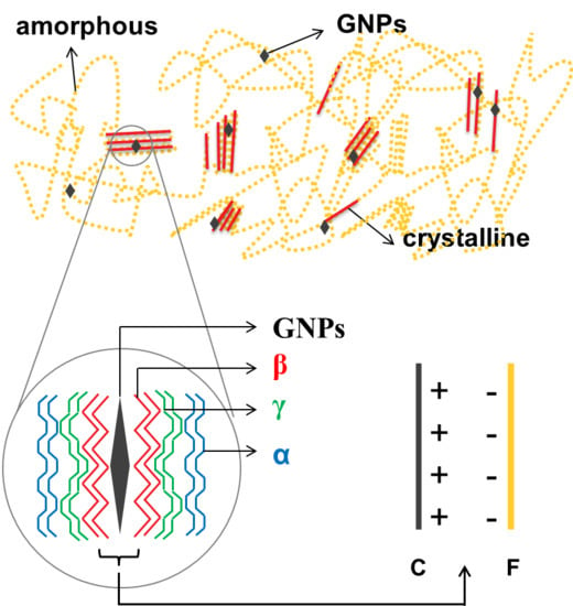
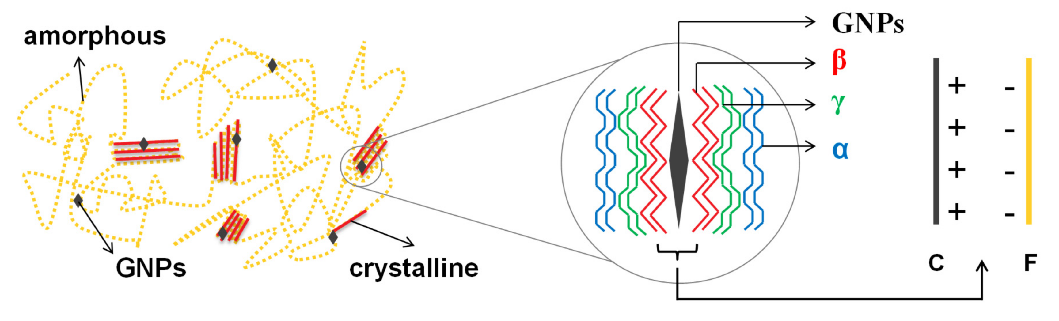
Figure 9 presents a schematic of the proposed mechanism of GNPs dispersal within P(VDF-HFP). P(VDF-HFP) is categorized as a semi-crystalline material and this kind of material contains both crystalline and amorphous areas in its structure. Actually, adding nanofillers is only one of the well-known methods to get the most electroactive crystalline phase. Compared to others such as melting process, applying external electric field or ultra-fast cooling, adding nanofillers, which is currently developed, has additional advantages that has no microstructural limitations or causing undesired deformation of the structure [
30]. When GNP nanofillers were introduced into the P(VDF-HFP) matrix, the GNPs spread throughout the whole of the polymer matrix in both crystalline and amorphous areas.
The mechanism of the specific phase nucleation process cannot be generalized. The prior works have reported that it has also influenced either by the nanofillers size or the nanofillers amount [
30]. Nevertheless, all of them are agreed with the dominant role of the interface interactions between the fillers and the matrix. The appearance of GNPs conducting nanofillers will produce local electric field that occurs around the nanoparticles. This electric field then attracting the randomly arranged dipoles of P(VDF-HFP). The nucleation of β-phase could be gained during this process. The dipoles that rotate depend on the type of the nanofillers itself. Simply, more positively charged particles will attract the negative CF
2 groups of the polymer, while the more negatively charged particles will induce the CH
2 group of the polymer.
In the composite containing the lowest GNP content of 1 wt%, the conducting fillers tended to interact with the crystalline areas as a consequence of the positively charged carbon atoms on GNPs, that attracted by the negative charge of the fluorine atoms in P(VDF-HFP). The crystalline areas of the P(VDF-HFP) matrix consisted of five crystalline phases including the α-phase, γ-phase and β-phase [
20]. This kind of interface interaction led to the transition of α-phases to β-phases, especially in those areas very closed to GNPs. Further, the γ-phase occurred in areas close to the β-phase and not too distant from GNPs. In areas far away from GNPs, the non-polar α-phase still existed, as illustrated in
Figure 9. The polymer chain rotation resulted in planar zig-zag conformation modes. Here, the C–F bond, which has higher electronegativity was reoriented parallel to the opposite side of the C–H bond [
18] and that is why the β-phase fraction increased significantly after the addition of only 1 wt% of GNPs, as shown by the FTIR results in
Figure 7 of β-phases fraction.
When the filler content was higher than 1 wt%, GNPs not only attracted the crystalline areas but also attracted the amorphous areas of the polymer. In the amorphous areas, the interaction that occurred between the P(VDF-HFP) matrix and the GNP nanofillers led to the creation of new crystalline areas, causing an improvement in overall crystallinity and overall crystalline phases. However, since overall crystallinity increased, the interaction between GNPs and amorphous areas created not only β-phases but also other crystalline phases including the non-polar α-phase formation. Therefore, the percentages of β-phase fraction seem to slightly decline as a proportion of the overall crystalline phases after increasing the GNPs filler content as shown by
Figure 7.
Nevertheless, the crystallinity and melting enthalpy of the films decreased after electron-beam irradiation compared to their values before electron-beam irradiation, as shown in
Table 2 and
Figure 8b, respectively. The
Tm of the neat P(VDF-HFP) film decreased from 160.67 to 160.17 after electron irradiation with a similar reduction in the HFP/GN composites. Tan et al. (2013) suggested that the reduction in melting temperature was caused by reduced crystallinity and smaller crystal size, which was confirmed by XRD analysis [
43] domain size [
43].
3.7. Dielectric Properties and AC Conductivity
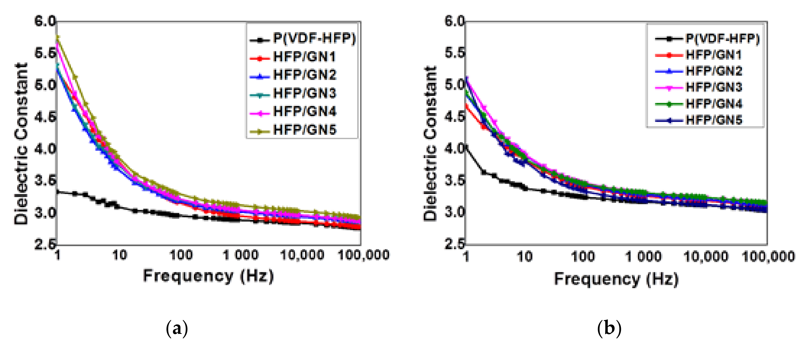
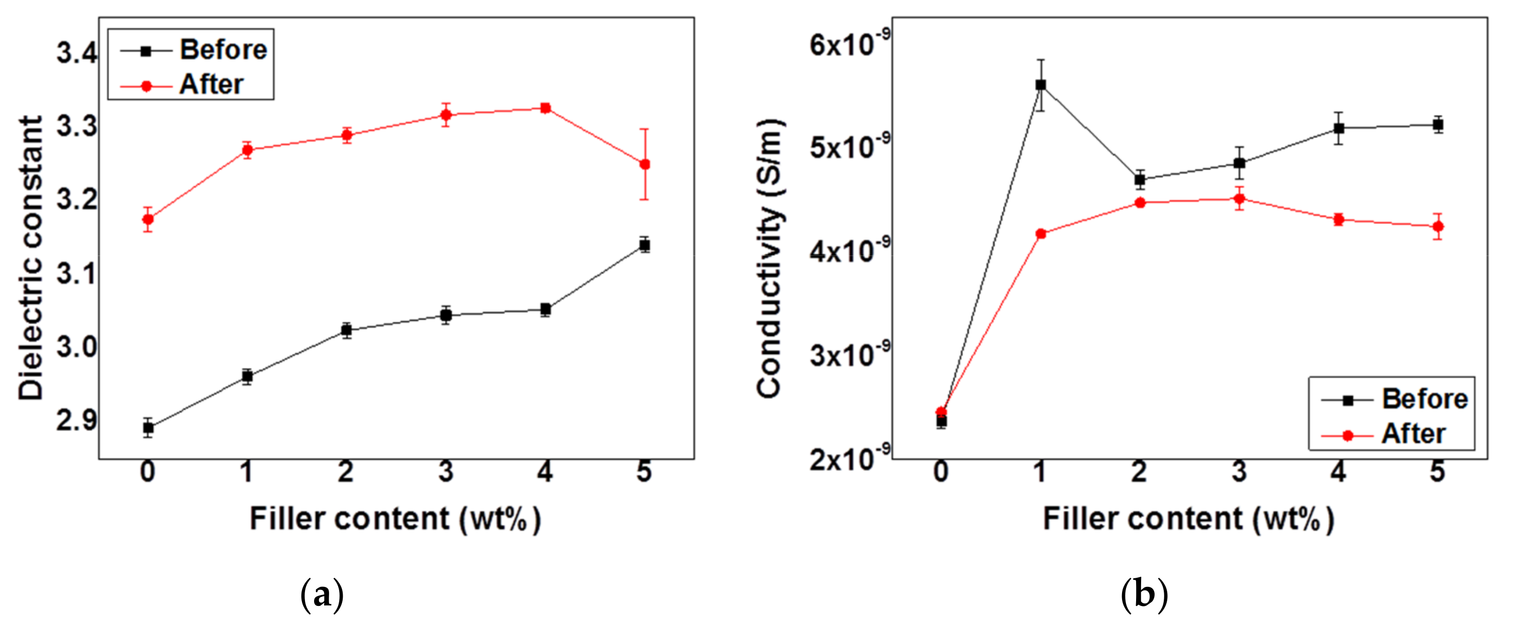
At room temperature, before and after electron-beam irradiation, the dielectric constant (
εr) of neat P(VDF-HFP) and various HFP/GN composites was dependent on the frequency of the electric field from 1 Hz to 100 kHz (
Figure 10a,b). The non-irradiated HFP/GN composites had a higher dielectric constant than non-irradiated neat P(VDF-HFP) over the whole frequency range. It indicates that the dielectric constant is also dependent on the fillers content.
As explained above, GNPs acted as micro-capacitor electrodes closely arranged in serial or parallel to each other but still in isolated systems [
23]. As found in a previous study [
41], the higher polarization of HFP/GN composites could improve the dielectric constant in two ways. The charged surface of the GNPs could provide a charge-movement contribution, and the GNPs could facilitate polar
β-phase formation, which increased dipole density and charge storage capacity. GNPs acted as nucleation agents that promoted crystallization. In addition, interfacial interactions between GNPs and the P(VDF-HFP) matrix stabilized the β-phase TTTT chain sequences of the P(VDF-HFP) and limited movement of the molecular chains during the process of crystal-formation [
41]. The molecular chains located near the β-phase TTTT chain sequences will even change into γ-phase TTTG without the direct influence of the surface of GNPs. Nevertheless, the α-phase TGTG chains were still found in the P(VDF-HFP) molecular chains but only when it is far enough from GNPs.
At low frequency of 1 Hz, the addition of 1%wt GNP increased the dielectric constant from 3.34 for neat P(VDF-HFP) to 5.26. The dielectric constant increased gradually with further GNPs loading to 5.27, 5.32, 5.62 and 5.77 for HFP/GN2, HFP/GN3, HFP/GN4 and HFP/GN5, respectively. In contrast, as the frequency increased, net polarization dropped due to the cessation all polarization mechanisms. The inability of the structural components in all repeat units to couple with the electric field prevented maximum reorientation of the dipoles [
46]. Hence, higher frequencies produced a reduction in the dielectric constant.
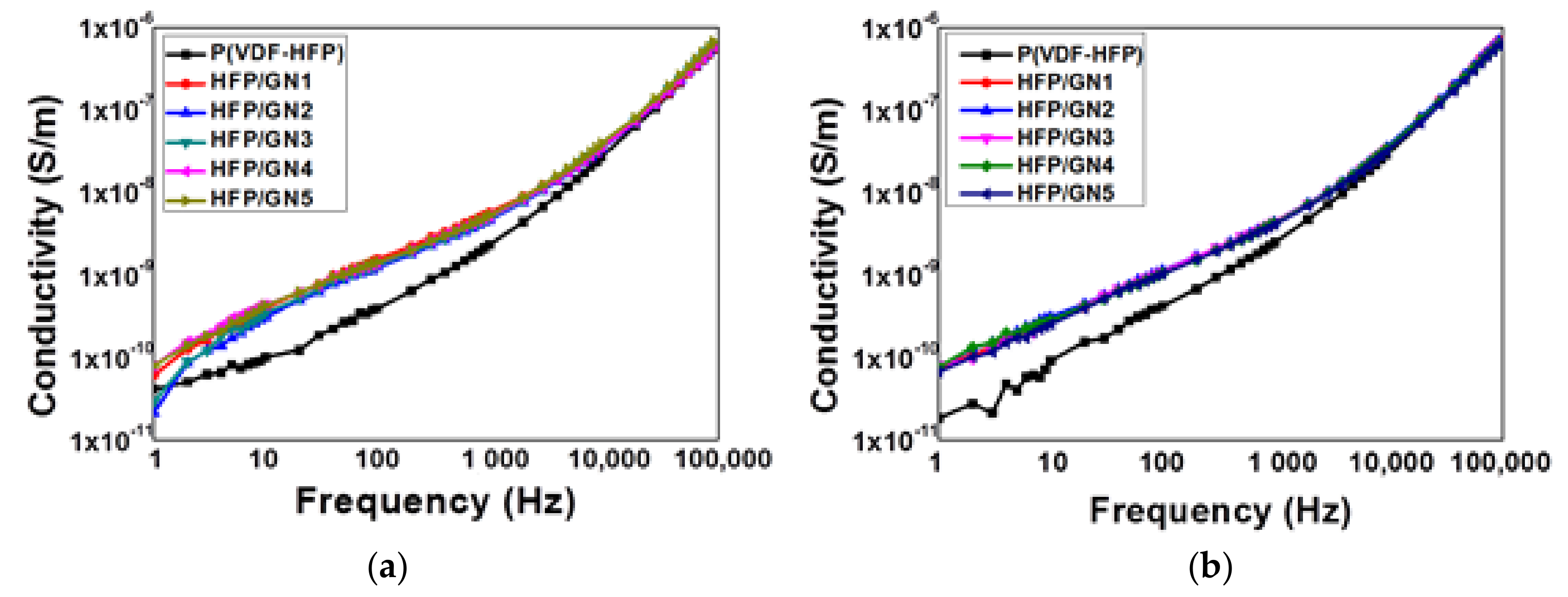
GNPs also improved AC conductivity of P(VDF-HFP) and dielectric loss (
Figure 11 and
Figure 12) which represent typical insulating behavior. The AC conductivity of the neat P(VDF-HFP) shows non-monotonous behavior. It can be seen that the AC conductivity increase almost linearly with the increasing of frequency. It might occur because it approaches or is closely the same with the resonance frequency of the charge carriers in the polymer chain. This frequency dependence of AC conductivity could be related to the activated trapped charges release [
47].
The increased AC conductivity in the HFP/GN composites may have been caused by their dipole density and GNPs themselves that are highly conductive. Although it is not significant, this AC conductivity improvement could be affected by several factors such as filler conductivity and filler concentration. Polymers that electrically resistant normally possess the electrical conductivity ranges of 10
−14 to 10
−17 S/cm. Those numbers are much lower than that of the Carbon-based fillers of 10
2 to 10
5 S/cm. Hence, the composites that incorporated by conducting filler will have higher conductivity as well. Further, the introduction of the filler into the matrix could gradually decrease the resistivity of the polymer. Nevertheless, the low filler concentration that used in this work does not affect to the conductive path formation that indicated by the very few amount of the GNPs particles that located nearly or contact each other as shown by SEM result in
Figure 3. In addition to filler conductivity and its concentration, another factor that influences the HFP/GN AC conductivity improvement is the aspect ratio of the filler. Graphene-based filler itself is well known as the material with high aspect ratio. As the aspect ratio boost up, the conductive path could be reached at lower filler concentration. This work confirmed the prior study that also reporting AC conductivity improvement that caused by GNPs nanofillers [
23].
As the fillers content increase (beyond 5 wt%), the formation of micro-capacitor that parallel each other will increase too. Continuously, the possibility of conductive network formation and leakage current will be higher too. So that, in one point, the percolation threshold could be reached. As the mechanism, the polymer’s insulating layer that is sandwiched by two GNPs conducting particles will decrease and cased the fillers to almost contact each other. At the percolation threshold or beyond, the dielectric constant and AC conductivity could be slightly improved. Along with the result of this work, a prior work has been reported the AC conductivity improvement that caused by GNPs incorporation [
23]. Moreover, it was reported also that the percolation threshold for GNPs conducting nanofillers in PVDF/PMMA matrix was beyond 4 wt%.
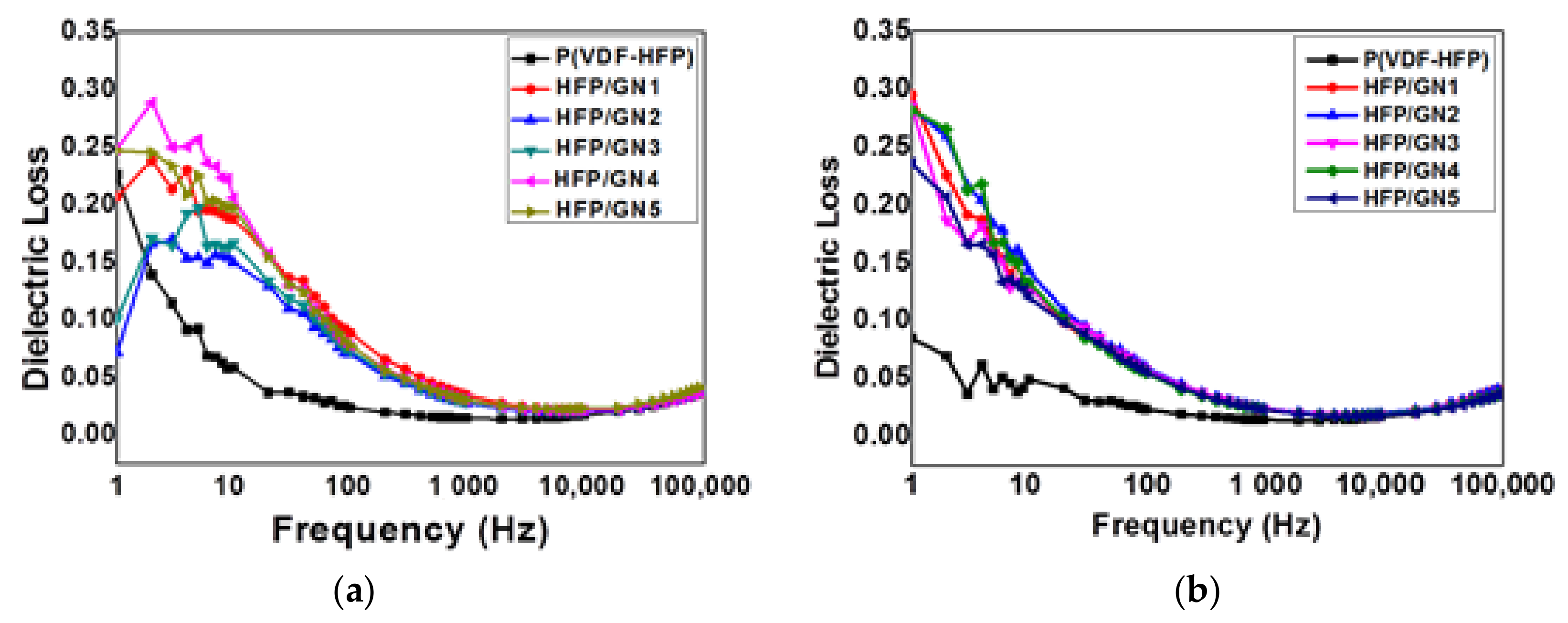
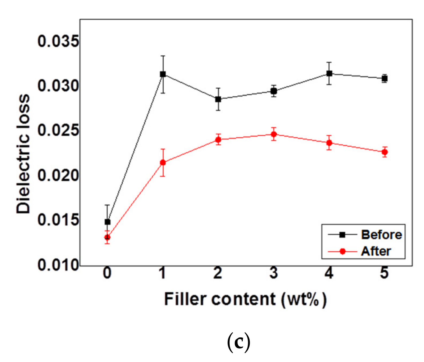
As aforementioned, the dielectric properties for both dielectric constant and dielectric loss were dropped as increasing the frequency. Inability of the dipoles to reorient following the applied electric field at high frequency led the reduction of the dielectric loss as well. As shown by
Figure 12, the dielectric loss for neat P(VDF-HFP) before and after electron-beam irradiation was decreased as increasing of frequency. When the GNPs conducting nanofillers were introduced to the P(VDF-HFP) matrix, the dielectric loss was increased since dielectric loss are also determined by the material’s conducting nature [
23]. Nevertheless, as neat P(VDF-HFP), the dielectric loss of the composites was also decreased as increasing of frequency. As well known, the dielectric properties including dielectric constant and dielectric loss for polar materials can be explained by the contribution of several types of polarizability components such as deformational period including electronic and ionic polarization and relaxation period including orientational and interfacial polarization. In low frequency, the total polarization was determined by the sum of those four polarization types. Since the ionic polarization does not play the significant role in the total net polarization, and the orientational polarization that usually take longer time to occur compared to electronic and ionic polarization, will lead to the reduction of the net polarization. Hence, at high frequency range, the polarization was only corresponded to the interfacial polarization.
The dielectric constant of both neat P(VDF-HFP) and the HFP/GN composites was higher after electron-beam irradiation at 1000 Hz (
Figure 13a), which was probably a result of the microstructural and morphological changes inside the material caused by the electron beam. As previously explained, microstructural changes in the samples due to electron-beam irradiation also influenced their electrical properties. The positively charged hydrogen atoms inside the P(VDF-HFP) chains attracted negatively charged electrons [
42]. Since the most stable non-polar α-phase dominates the original state of P(VDF-HFP) copolymer, the negative charge from the electron beam produced a more ordered crystalline phase and transitioned α-phases to γ-phases and β-phases [
33]. In addition, the electron beam helped the GNPs in the HFP/GN composites to act as nucleation agents in the formation of polar β-phases.
Both AC conductivity and dielectric loss were also increased after adding GNPs nanofillers to P(VDF-HFP) matrix. This condition could lead to the formation of conductive path and leakage current. It was suggested the GNPs framework interconnection in the P(VDF-HFP) matrix that resulting on charge transfer improvement in the composites. The AC conductivity and dielectric loss improvement of HFP/GN1 composites looks sharper than others. It might be caused by the dispersion of the GNPs in the HFP/GN composites. According to SEM results in
Figure 3, the agglomeration of the GNPs filler in HFP/GN1 composites can be observed associated to the bigger size of the GNPs group. It is along with the work that was previously reported that explains that the non-uniform distribution of the filler in the polymer matrix could lead to improve the conductivity, and dielectric loss as well due to the agglomeration [
48]. This phenomenon was commonly observed in many polymer composites behavior. Further, the curve of dielectric loss shows the similar pattern to the AC conductivity since it is also well known that the dielectric loss is originally determined by the natural electrical conductivity of the materials [
49].
Meanwhile, AC conductivity and dielectric loss of all composites were lower after electron-beam irradiation (
Figure 13b,c). A previous study of electron-beam irradiation of Poly(vinylidene fluoride-trifluoroethylene) copolymer with 50 mol% TrFE (P(VDF&HIPHEN;co-TrFE)) reported the effects on chemical pinning of the reduced crystal domains [
24]. However, the specific mechanism inside the material by which this occurs is still unclear, although the researchers considered that electron-beam irradiation caused cross-linking in the material. Chemical cross-linking expands the length of the inter-chain and pins polymer chains. As a consequence, it may decrease the crystal domain size and help the dipole moments to rotate during electrical discharge. Hence, the dielectric loss will decrease and the dielectric constant will increase [
43]. These electrical properties mechanism finally affect to other parameter such as ferroelectric loop as well as energy properties of the materials. Uniquely, the ability of the electron beam on suppressing the AC conductivity and dielectric loss seems stronger than the effect of GNPs conducting nanofiller itself on gaining those parameters. Hence, as shown by
Figure 13b,c, the AC conductivity and dielectric loss of the composites look not significant change after electron-beam irradiation even though the filler contents were increased.
3.8. P-E Loop
PVDF-based polymers, including P(VDF-HFP), are semi-crystalline materials in which amorphous and crystalline areas moderate the polarization response to an external electric field. Since PVDF-based polymers are ferroelectric materials, the polarization response to the electric field exhibits a ferroelectric hysteresis loop. Normal ferroelectric materials contain a large number of spontaneous dipoles that are packed on a relatively wide ferroelectric crystalline domain. This condition can produce a strong polarization response to an applied electric field.
As regards the mechanism when E is applied to thin films, the dipoles in the film will be rearranged to align with the direction of E, which is known as the charging process until the maximum polarization (Pmax) value is reached. However, the dipole directions will revert to a random state when E is removed from the system, and polarization will drop until E is equal to zero. This step is known as the discharging process. Nevertheless, not all the dipoles will rearrange themselves in their original state and larger crystalline domains will retain some charge, which is trapped and cannot be released. As a consequence, some dipoles will still exhibit an ordered orientation and will remain polarized. This state is described as the remnant polarization (Pr), at E = 0. Here, polarization is not zero even though there is no longer an applied electric field, and remnant polarization can be high.
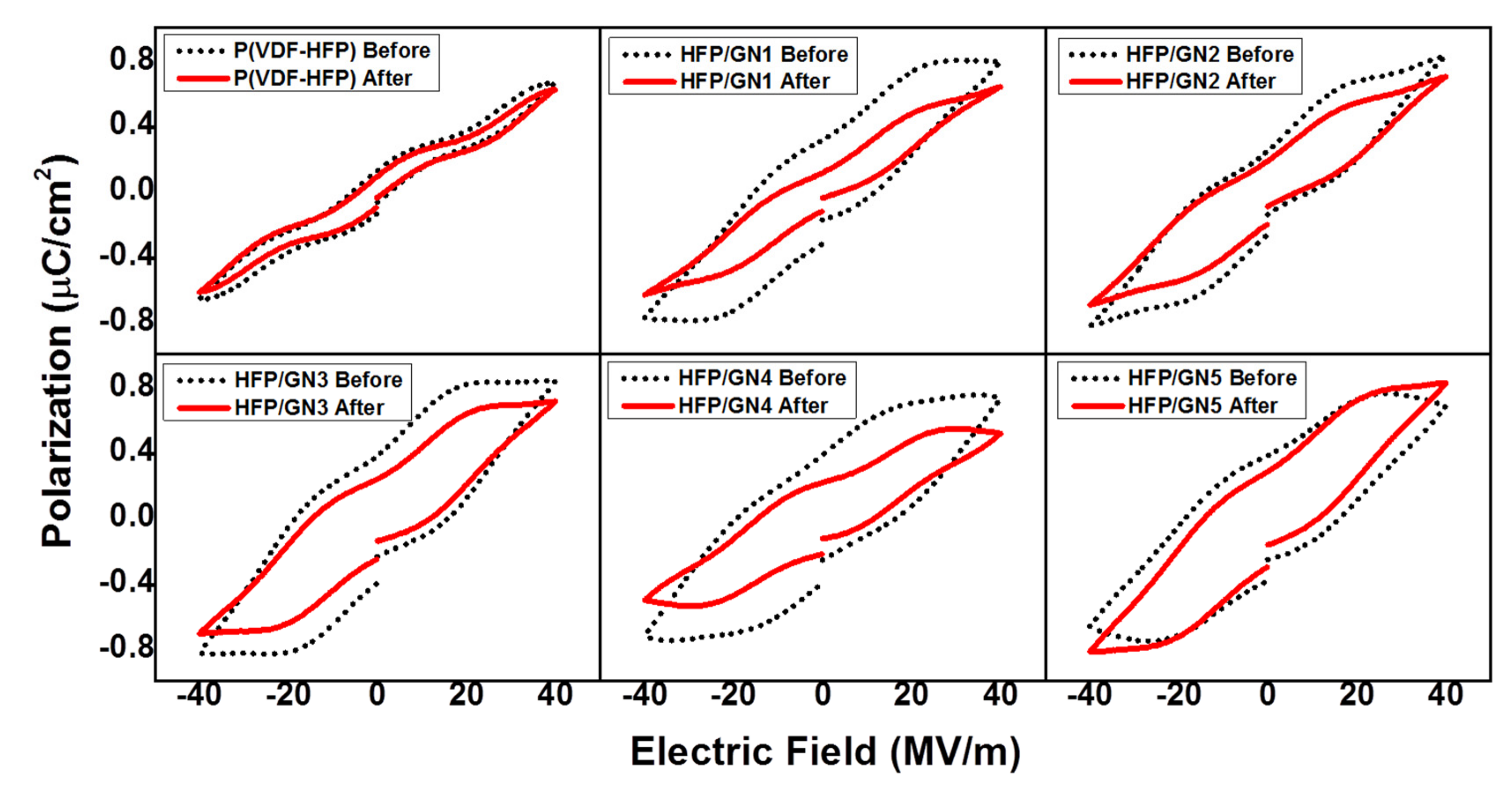
The polarization (
P) response of neat P(VDF-HFP) and HFP/GN composites to an externally applied electric field (
E) was measured at room temperature (30 °C). The P-E hysteresis loop gradually increased in size with increments of GNP and remnant polarization was exhibited (
Figure 14). Loop size is an indication of the size of the ferroelectric domain and is closely linked to dipole reversibility. A larger crystal size means a bigger energy loss. A large domain normally formed a large coupling force with other aligned domains nearby [
50]. Strong interactions between domains will prevent the relaxation of the dipoles during the discharging process, preventing dipole reorientation once the external
E is removed. This was also confirmed by dielectric measurements. Dielectric constant, AC conductivity and dielectric loss all improved after adding GNPs, since the GNPs are a conducting material. As a result, the composites possessed higher remnant polarization resulting in bigger loops compared to the loop of neat P(VDF-HFP).
Electron-beam irradiation had a similar effect to GNPs on the dielectric constant of P(VDF-HFP), promoting β-phase formation. The additional beneficial effects of irradiation included improved dielectric constant and possess better energy storage properties. Previous studies reported that electron-beam irradiation was effective at reducing dielectric loss [
28]. Its ability to pin the all-
trans conformation domain size of neat P(VDF-HFP) and HFP/GN composites improved dipole reversibility [
24]. The large domains of normal ferroelectrics can be pinned and cut into smaller domains. Electron-beam irradiation is also able to shorten P(VDF-HFP) segments and facilitate dipolar switching during discharge. After being pinned by the electron-beam, the small domains/crystal sizes were able to reverse freely because the forces holding domains were lower. As a result, dielectric loss decreased. Moreover, the P-E loops (
Figure 14) confirmed that remnant polarization also decreased in all composites after electron-beam irradiation. The loops were clearly slimmer after electron-beam irradiation.
3.9. Energy Efficiency
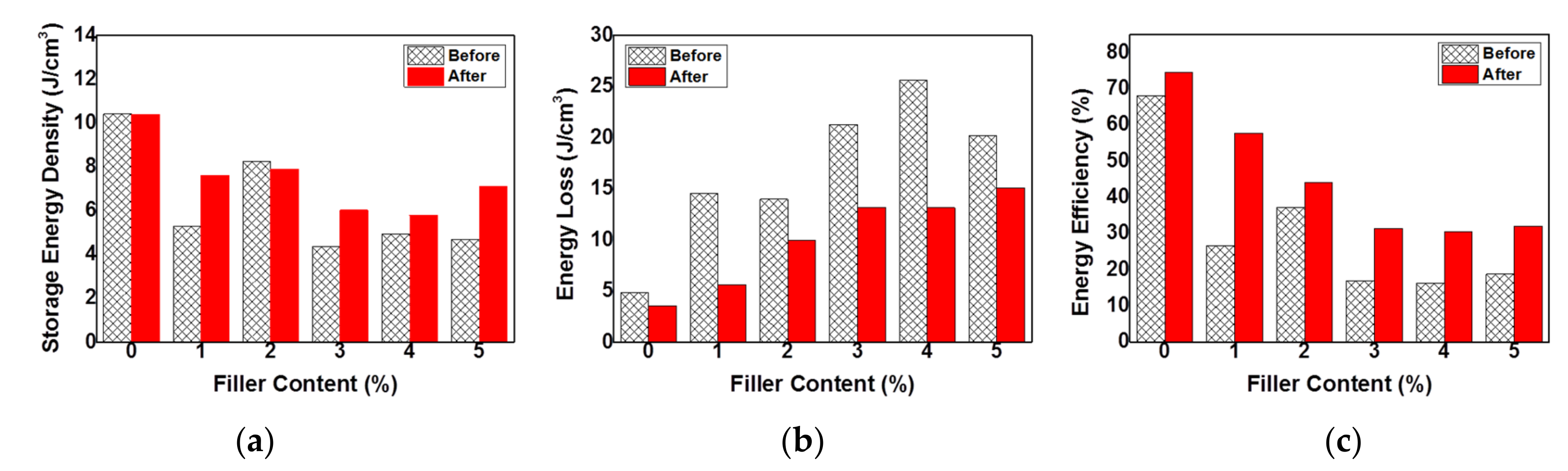
As previously mentioned, even though the GNPs conducting nanofillers improved the dielectric constant by promoting β-phase formation, GNPs also promoted increased dielectric loss. Compared to neat P(VDF-HFP), storage energy density of the composites tended to be lower at all loadings of GNPs from 1 to 5 wt%. The energy density was decreased by the increasing of the filler content. Hence, the energy loss was significantly increased, as shown in (
Figure 15a,b). As explained, GNPs could lead the improvement of AC conductivity and dielectric loss as well. Thus, the increasing of the proportion of GNPs in the composites produced a bigger loop indicating bigger energy loss. The reversibility of the dipoles was decreased resulting to the difficulties of the dipoles on following the electric field when it was removed from the system. Hence, this energy loss improvement affected to reduce the storage energy density.
Interestingly, different with the effect of adding GNPs conducting nanofillers, electron-beam irradiation was able to improve the storage energy density but reduce the energy loss of all samples. It also reduced the remnant polarization of the loop, thus assisting the release of the charge stored on the film’s surface [
43], resulting in lower dielectric and energy loss.
The final parameter considered was energy efficiency, which describes the ratio of storage energy density to energy loss. There are two ways to improve the energy efficiency of materials: increasing the storage energy or decreasing the energy loss. The storage energy density is the energy that can be released per unit volume and is usually calculated during electric field discharge. Energy loss relates to unreleased energy and occurs when energy is transferred from one system, place or condition to another. Mathematically, storage energy density (
Ue) and energy loss (
Ul) can be expressed by the following equations:
and
where
E and
D are respectively the applied electric field and electrical displacement, while
εr,
ε0 and
Eb are the dielectric constant (measured permittivity), vacuum permittivity (8.85 × 10
−12 F/m) and electrical breakdown strength, respectively. ω represents frequency and ε” refers to the dielectric loss [
28,
43]. According to these equations, in the same applied electric field, storage energy density will depend only on the dielectric constant, while energy loss is closely related to dielectric loss.
Electron-beam irradiation considerably improved the energy efficiency of P(VDF-HFP) and HFP/GN composites (
Figure 15c) by increasing the dielectric constant while simultaneously reducing the dielectric loss, thus increasing
Ue and reducing
Ul. For example, the energy efficiency of neat P(VDF-HFP) increased from 68.11 to 74.66% after irradiation, which is much higher than the efficiency reported by Guan et al. (2010) [
13] who only achieved 58% for P(VDF-HFP) without electron-beam irradiation and 30.2% for PVDF [
12]. The energy efficiency of HFP/GN1, HFP/GN2, HFP/GN3, HFP/GN4 and HFP/GN5 also increased after electron-beam irradiation, in some cases almost doubling, from 26.65, 37.10, 16.98, 16.16 and 18.75%, to 57.7, 44.23, 31.34, 30.59 and 32.06%, respectively.


