Advances in the Applications of Graphene-Based Nanocomposites in Clean Energy Materials


1
Guizhou Provincial Key Laboratory for Information Systems of Mountainous Areas and Protection of Ecological Environment, Guizhou Normal University, Guiyang 550001, China
2
Cultivation Base of Guizhou National Key Laboratory of Mountainous Karst Eco-Environment, Guizhou Normal University, Guiyang 550001, China
3
Department of Applied Chemistry, College of Chemistry and Molecular Engineering, Peking University, Beijing 100871, China
*
Author to whom correspondence should be addressed.
Crystals 2021, 11(1), 47; https://0-doi-org.brum.beds.ac.uk/10.3390/cryst11010047
Submission received: 7 December 2020
/
Revised: 1 January 2021
/
Accepted: 4 January 2021
/
Published: 7 January 2021
(This article belongs to the Special Issue Graphene-Based Nanocomposites and Manufacturing)
Abstract
:Extensive use of fossil fuels can lead to energy depletion and serious environmental pollution. Therefore, it is necessary to solve these problems by developing clean energy. Graphene materials own the advantages of high electrocatalytic activity, high conductivity, excellent mechanical strength, strong flexibility, large specific surface area and light weight, thus giving the potential to store electric charge, ions or hydrogen. Graphene-based nanocomposites have become new research hotspots in the field of energy storage and conversion, such as in fuel cells, lithium-ion batteries, solar cells and thermoelectric conversion. Graphene as a catalyst carrier of hydrogen fuel cells has been further modified to obtain higher and more uniform metal dispersion, hence improving the electrocatalyst activity. Moreover, it can complement the network of electroactive materials to buffer the change of electrode volume and prevent the breakage and aggregation of electrode materials, and graphene oxide is also used as a cheap and sustainable proton exchange membrane. In lithium-ion batteries, substituting heteroatoms for carbon atoms in graphene composite electrodes can produce defects on the graphitized surface which have a good reversible specific capacity and increased energy and power densities. In solar cells, the performance of the interface and junction is enhanced by using a few layers of graphene-based composites and more electron-hole pairs are collected; therefore, the conversion efficiency is increased. Graphene has a high Seebeck coefficient, and therefore, it is a potential thermoelectric material. In this paper, we review the latest progress in the synthesis, characterization, evaluation and properties of graphene-based composites and their practical applications in fuel cells, lithium-ion batteries, solar cells and thermoelectric conversion.
1. Introduction
Green energy is also called clean energy, including solar energy, wind energy, water energy, tidal energy, geothermal energy and biomass power, whereas fossil fuels are non-renewable energy sources, including coal, crude oil, natural gas, oil shale, oil sand and combustible ice under the sea [1,2]. The burning of fossil fuels produces a huge amount of toxic gases, polluting the environment and the food chain and causing the greenhouse effect [3]. With the rapid expansion of the world economy and the rising population, human beings are increasingly dependent on fossil fuels [4]. From 1987 to 2012, the average growth rate of energy consumed in the past 25 years has risen by more than 50%, and the demand will double in the next decade; therefore, it is necessary to seek clean energy sources [5,6,7]. Currently, clean energy material faces the challenges of high cost, low conversion efficiency, and poor recycling. In order to tackle the above problems, graphene-based nanocomposites with unique properties are studied extensively for their potential applications in clean energy-related areas, e.g., hydrogen fuel cells, lithium-ion batteries, solar cells, thermoelectric conversion and other environmental and energy fields.
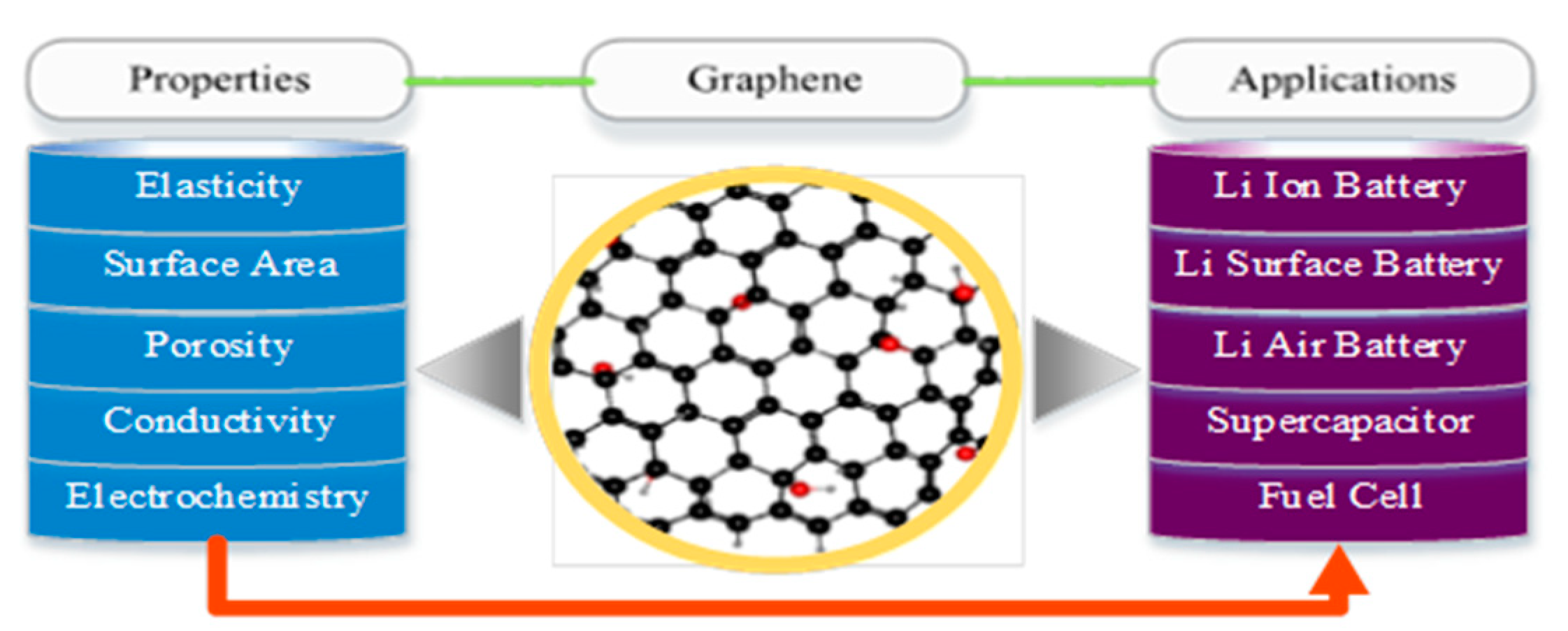
Graphene is a nanomaterial composed of a single-atom thick sp2-bonded carbon structure, which has crystallinity, electrical properties and different levels of physical and chemical properties [8,9,10]. These properties include excellent mechanical strength, high electrical conductivity, strong flexibility, large specific surface area and light weight, thus giving the potential to store electric charge, ions or hydrogen [4,11]. In 2018, Cao et al. [12] twisted the two-layer single-layer graphene material to a special angle and supplemented it with an electric field to control the carrier concentration; this system can produce superconductivity at low temperatures. Nevertheless, the field is still in the ascendant stage and many experimental observations have not accepted theoretical explanation—for instance, although graphene is initially highly conductive, this material can become an insulator when the system is electrically neutral [13].
As an electrochemical system, hydrogen fuel cells (HFCs) are a green energy conversion device with high efficiency and environmental friendliness. The cation transport capability of graphene oxide (GO) and its impermeability to molecular fuels make it an inexpensive and sustainable membrane for hydrogen fuel—proton exchange membrane fuel cells (PEMFCs) [7]. Lithium-ion batteries (LIBs) are modern energy storage devices with high energy density and long-period stability. Doping heteroatoms (nitrogen, boron and phosphorus) into the graphene carbon lattice in Li-ion batteries can effectively customize the properties of pristine graphene such as semiconductor properties, surface reactivity, electronic properties, band structure and magnetic properties [9,10]. These advantages enable LIBs to have good reversible specific capacity, rate capability, high capacity retention capacity and improved charging speed. Solar cells as a renewable energy device friendly to the environment use the performance of the interface and junction, which is enhanced by using a few layers of graphene-based composites and more electron-hole pairs are collected; therefore, the power conversion efficiency is increased. The design of a closed-loop cycle for an electrolyzer and fuel cells to produce hydrogen and electrical energy to generate, store, transport and use hydrogen from solar energy should be the important technology combination [14]. Therefore, the future of a clean energy society should be realized through hydrogen-mediated energy conversion systems. Guan et al. [15] immobilized manganese-containing oxide nanoparticles on graphene nitride as a matrix. The results showed that the water oxidation activity of the heterogeneous catalyst was the highest as its level reached natural photosynthetic water oxidation of multinuclear manganese catalysts. Solar energy is used to generate electricity which then electrolyzes water to produce hydrogen and hydrogenate carbon dioxide into methanol fuel. Thermoelectric conversion can directly convert waste heat into electric energy, which is an effective means of waste heat management. Graphene has become a potential thermoelectric material due to its high Seebeck coefficient [16]. In addition, artificial intelligence (AI) technologies are also applied to environmental protection and clean energy, which take advantage of feed-forward artificial neural networks and adaptive neural fuzzy inference systems (ANFISs) for process modeling [17,18,19].
As is shown above, graphene and its composites own many unique properties, giving it a high potential to be used in clean energy materials in order to curb environmental pollution and facilitate the sustainable development of our humanity; thus, a review is clearly needed to summarize advances in this aspect. In this paper, we discuss the preparation and characterization of these materials, e.g., preparation with chemical vapor deposition, mechanical exfoliation, oxidation reduction and SiC epitaxial growth methods, and characterization with X-ray diffraction (XRD), electron energy-loss spectroscopy (EELS), field emission scanning electron microscopy (FESEM) and high-resolution transmission electron microscopy (HRTEM). We also review the progress in their applications in green energy materials, e.g., replacing precious metal materials as catalysts in hydrogen fuel cells, increasing the cycle stability and competitive rate performance as electrode materials in lithium-ion batteries and enhancing power conversion efficiency in solar cells and thermoelectric conversion. In addition, we use mathematical models to evaluate these applications and point out the current problems and future research directions in this field.
2. Preparation of Graphene-Based Nanocomposites Materials
Nanomaterials are classified into the following four categories: zero-dimensional nanomaterials (0D), including quantum dots and nanoparticles; one-dimensional nanomaterials (1D), comprising nanowires, nanorods, nanobelts and nanotubes; two-dimensional nanomaterials (2D), including nanosheets, nanomembranes and nanoplatelets; three-dimensional nanomaterials (3D) of hierarchical structures composed of the above-mentioned nanomaterials as basic units, such as flower balls assembled from nanosheets and hollow microspheres assembled from nanorods [20].
There are mainly three forms of graphene: graphene powder, graphene film and graphene liquid. The fabrication methods of graphene powder primarily include mechanical stripping, oxidation reduction and SiC epitaxial growth; the manufacturing of graphene films mainly involve chemical vapor deposition (CVD) and electrochemical and rapid heating methods, and graphene liquids contain mostly graphene derivatives [21]. Oxidation reduction was conducted by using the Brody, Hummer and Hoffman method and Staudenmaier methods. The preparation of GO is based on the oxidation of graphite by potassium chlorate in fuming nitric acid, and several procedures have been developed dealing with chlorate and nitric acid (Brodie method) or their mixture with sulfuric acid (Hofmann and Staudenmaier methods) [10,22,23]. Mechanical exfoliation was carried out by using transparent tape, liquid phase, graphite intercalation compound, electrochemical stripping and ball-milling [8,24,25,26]. These methods can prepare single-layer graphite and a small amount of graphene by peeling off natural graphite or synthetic graphite, and graphene can be prepared directly from carbon by CVD or SiC epitaxial growth [10,21,27].
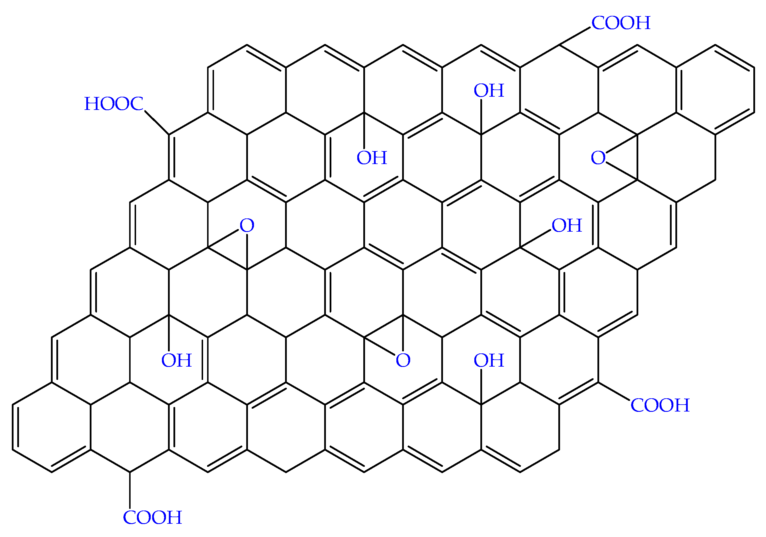
Ruan et al. [28] prepared GO by using Hummer’s method. At first, certain quantities of graphite powder and NaNO3 were placed into H2SO4 in a beaker under continuous stirring. Next, a certain quantity of KMnO4 was slowly added, heated and reacted under stirring. Finally, H2O2 was added to the above reaction mixture and washed with dilute HCl and deionized water [29,30,31]. Chang et al. [32] alreported the preparation of GO using the Staudenmaier method as follows. Graphite was added to a mixture of sulfuric and nitric acid. Potassium chlorate was added slowly to avoid a sudden increase in temperature and stirred at room temperature, filtered and washed repeatedly with HCl and deionized water. Tan et al. [33] demonstrated that graphite oxide could be prepared by the Hoffman method as follows. At first, sulfuric and nitric acid was cooled to 0 °C, and graphite was added with vigorous stirring. Next, within 30 min, KClO3 was added to the mixture, and the lid of the reaction flask was opened to release chlorine dioxide gas. The temperature was raised to room temperature, and after the mixture was continuously stirred for 96 h, 3 L of deionized water was added to the mixture. Then, deionized water and 5% hydrochloric acid were added to the mixed liquid separately, stirred into slurry and solid–liquid separation was realized by a centrifuge. Finally, it was dried in a vacuum oven for 48 h. The chemical structure of GO is shown in Figure 1.
There are many reports on the preparation of graphene-based nanocomposites—for instance, ZnO nanoparticles can be dispersed with distilled water and tert-butanol to form a ZnO paste, and carbon nanomaterials were added to prepare graphene/ZnO nanocomposites films [32]. To prepare the WS3−X/rGO hybrids, GO was dispersed in dimethylformamide for ultrasonic treatment, and then, an aliquot of the dispersed droplet was immobilized on the bare, glassy carbon electrode; the suspension was dried under a lamp [33]. Zhang et al. [34] demonstrated how TiO2-graphene aerogel hybrids were prepared. At first, anhydrous ethanol was added to the GO solution, which was prepared by a modified Hummer’s method and ultrasonically processed. Then, tetrabutyl titanate was added, and the reactant was sonicated. Next, the mixture was transferred to a stainless steel autoclave lined with Teflon, and TiO2-graphene hydrogel was subjected to hydrothermal treatment. Han et al. [35] fabricated SnO2/rGO nanocomposites using SnCl2 and GO precursors though a simple sonochemical method. In the process, Sn2+ was first uniformly dispersed on the surface of GO, and then, SnO2 nanoparticles were oxidized in situ on both sides of graphene sheets with reducing GO under the action of continuous ultrasound.
In the electrochemical method, appropriate electrolyte and electrolysis conditions are the key to preparing graphene [21]. The electrochemical exfoliation of charcoal and graphite with different electrolytes was studied. Copper foil was used as a cathode and graphene as an anode. Both electrodes were immersed in electrolytes. Direct current voltage was applied to the electrochemical process to exfoliate graphite. In the same procedure, after using carbon as an anode to peel off charcoal, graphene sheets were obtained, and it was found that graphite rods were more effective than charcoal at forming suitable graphene sheets in the peeling process.
In the mechanical exfoliation method, the van der Waals force between the graphite molecular layers was overcome by physical force, and the graphite sheets were separated to obtain graphene. Ma et al. [36] reported that graphite powder was added into honey to obtain monolayer and multilayer graphene by mechanical exfoliation and stirring.
The top-down and bottom-up methods are commonly used to prepare graphene quantum dots [37]. In the top-down method, large-sized materials are cut into carbon sources containing a large amount of graphene structure and divided into quantum-sized graphene quantum dots through a series of physical, chemical or electrochemical methods. In the bottom-up method, graphene quantum dots are synthesized by the chemical method from small molecular carbon sources. Graphene quantum dots can be controlled in the process of preparation and post-treatment, so it is necessary to carefully optimize the preparation method. The surface passivation, functionalization, heteroatom doping or recombination of graphene quantum dots meets the needs of different applications. In the SiC epitaxy growth method, SiC single crystal is heated at a high temperature so that the Si atoms on the surface of SiC are evaporated and separated from the surface and the remaining carbon atoms are reconstructed by self-assembly to obtain graphene based on silicon carbide substrate [38].
In the CVD method, graphene is synthesized by decomposing methane and other carbonaceous compounds at a high temperature [39]. The growth mechanism can be divided into the following two categories: (a) The mechanism of carburizing and carbon deposition is that for metal substrates with a high carbon capacity such as nickel. The carbon atoms generated by the cracking of the carbon source penetrate the metal substrate at a high temperature, and then, the nucleation is precipitated from the inside when the temperature is lowered. (b) The surface growth mechanism, where the carbon atoms generated by the pyrolysis of a gas carbon source are adsorbed on the metal surface by copper and other low carbon metal matrix nucleates into graphene with growth at high temperatures. In rapid thermal treatment (RTT), high-quality graphene is synthesized from amorphous silicon carbide (a-SiC) by RTT. The SiO2/Si substrate is first covered with a-SiC film, and Cu and Ni films are deposited sequentially [40]. Then, the sample is thermally annealed by RTT and high-quality graphene is prepared in 3 min.
Ball milling is a common technology in the powder industry, which is a good method to produce shear force [24]. Both wet and dry ball milling methods are widely used to prepare graphene. The spheroidal grinding method is characterized by shear stress and high energy, which can prepare functional graphene.
3. Characterization of Graphene-Based Nanocomposites
In order to obtain the physicochemical properties of graphene-based nanocomposites (structure, shape, particle size, size distribution, valence state and specific surface area), these materials can be characterized by various techniques (Table 1). X-ray photoelectron spectroscopy (XPS) is mainly used to study the elements on the surface of materials and their different valence states. Peng et al. [41] synthesized high-performance graphene-supported electrocatalysts by laser-assisted solution. The valence state characterization of Ru by XPS showed that Ru mainly existed in the Ru4+ state, while Pt mainly existed in the Pt0 form, and a small part was Pt2+. A multi-collector inductively coupled plasma mass spectrometer (MC-ICPMS) is an elemental analysis instrument with a plasma ion source which can be used for the determination of element content and isotope analyses of samples. Vio et al. [42] revealed four lanthanide samples (Nd, Sm, Eu and Gd) that were isotopically characterized by MC-ICPMS. The isotope composition of heavy metals in pollutants can be used to determine the source; then, effective methods can be adopted to remove the pollutants. For example, Fan et al. [43] used rGO-supported nanoscale zero-valent iron composites to remove cadmium in aqueous solutions.
XRD was used for phase analysis of crystalline materials based on diffraction peak intensity, angular positions, relative intensity order and the shape of the diffraction peaks [44]. Iqbal et al. [45] fabricated a high-sensitivity shortwave infrared hybrid photodetector by integrating an organic charge transfer compound on a graphene transistor. XRD characterization confirmed that the prepared tetrathiafulvalene–chloranil film was polycrystalline, in which tetrathiafulvalene and chloranil molecules were stacked alternately along the a-axis.
Thermogravimetric analysis (TGA) is a method to measure the relationship between mass and temperature or time under programmed temperature. The composition, thermal stability and possible intermediate products could be obtained by analyzing the thermogravimetric curve [44]. Feng et al. [46] studied three graphene materials with different structures as the cathode of lithium-sulfur batteries. Pure sulfur has the characteristic of one-step weight loss in the temperature range of 190–300 °C by TGA. In the same temperature range, the three carbon/binary composites reproduced the weight loss curve of pure sulfur, and this the reason for the loss of sulfur. Scanning electron microscopy (SEM) is a surface imaging method in which the sample surface is scanned by an incident electron beam [47]. This interacts on the sample surface to generate signals reflecting the atomic composition and morphology of the sample surface, as well as the surface and cross-section morphology. Li et al. [48] studied the intercalation modulation method of graphene assembly and analyzed the fracture morphology of the material by SEM. It was found that the fracture of the plasticized graphene oxide paper was H-type. This indicated that the interlayer slip was activated by solvent intercalation, which determined the plastic transition of the paper. The structural information of molecular vibrational and rotational energy levels can be obtained by Raman spectroscopy analysis, so as to identify chemical bonds and functional groups of materials [44]. Tavakkoli et al. [49] reported graphene-based nanocomposites that were characterized by Raman spectroscopy, and it was found that the ID/IG = 0.06 of the material without N doping, and the ID/IG = 0.1 of the N-doped sample. The results demonstrated that the graphitization degree of N-doped carbon materials was high. EELS is the inelastic scattering of an incident electron beam in a sample, which is analyzed to obtain the element composition, chemical bond and electronic structure of samples [50]. Wang et al. [51] showed that the chemical bond configuration of BeO in a graphene reaction cell had obvious in-plane and inter-plane anisotropy through EELS characterization.
FESEM can be used to observe the surface morphology of nanomaterials. Zhang et al. [52] utilized FESEM to observe N-doped GO aerogels and graphene foam skeleton composites. It was found that this material maintained a porous and interconnected network structure and GO plates possessed obvious defects, which made N doping possible. Nuclear magnetic resonance (NMR) is a non-destructive testing method which does not interfere with the measurement system. Information such as molecular structure and dynamics can be obtained by detecting nuclear magnetic resonance signals. Among the NMR methods, 1H-NMR and 13C-NMR are the most widely used to determine molecular structures. Calovi et al. [53] described that solid-state NMR could confirm C-related dangling bonds and groups linked to hydrogen such as carboxyl, alcohol, epoxy and hydroxyl. X-ray powder diffraction (PXRD) is usually used to analyze the phase, purity, grain size, crystallinity and lattice parameters of materials. Xiong et al. [54] adopted PXRD to characterize the prepared COFETBC-TAPT-graphene heterostructure ultra-sensitive photodetector and concluded that COFETBC-TAPT was highly crystalline due to strong diffraction peaks at 3.08° and 4.31°.
Cyclic voltammetry (CV) is commonly used to detect electrode reaction parameters and determine its control steps and reaction mechanism. Zhang et al. [55] obtained the potassium storage mechanism of rGO by cyclic voltammetry and other methods, which showed that rGO significantly increased the specific capacity, cycle performance and rate performance of potassium-ion battery. Nitrogen adsorption can be used to analyze the specific surface area, pore size distribution, porosity, surface properties and other parameters of materials [56,57]. Cheng et al. [58] performed nitrogen adsorption/desorption (77.4 K) characterization on three-dimensional graphene and N-doped three-dimensional graphene (3D-PNG) materials. The results showed that the isotherms of 3D-PNG belong to type IV, when the relative pressure P/P0 is 0.4 to 1, which is different from that of 3D-rGO. Generally, small-angle X-ray diffraction (SAXRD) is an important method to determine the ultra-large crystal plane spacing or film thickness as well as the micro periodic structure and periodic pore distribution of thin films. Hou et al. [29] characterized graphene composites by SAXRD and concluded that the Mn-doped Fe/rGO nanocomposites were partially ordered mesoporous materials.
HRTEM is a method to observe the internal structure, atomic arrangement and many fine structures (such as dislocations, twins, etc.) in crystals. Gao et al. [59] observed that graphene nanosheets were surrounded by graphite structures formed by polyacrylonitrile carbonization through HRTEM. Combined with other characterization techniques, it was disclosed that graphene could improve the mechanical properties of carbon fibers. An atomic force microscope (AFM) detects an object through the probe, obtains the three-dimensional surface image of the sample surface and calculates the roughness, thickness and analysis of the three-dimensional morphology image. Yuan et al. [60] characterized graphene films grown on Cu substrates using an AFM. The images showed that there were clear atomic steps on the surface of the material, and wrinkles appeared along or perpendicular to the Cu atomic steps, indicating the existence of graphene films.
Fourier-transform infrared spectroscopy (FTIR) is applied to observe the bonding structure of a sample and interaction in a mixed film; the stretching and bending vibration absorption spectra of chemical bonds in the sample can be obtained [61]. Ali et al. [62] revealed via an FTIR study that the surface defects of N-doped graphene quantum dots were caused by strong surface oxidation or surface functional groups. Scanning electrochemical microscopy (SECM) is an electrochemical method based on a microscope which provides the transverse resolution characterization of an electrode surface, and the tip is located near the sample surface as a local sensor for detecting reaction products generated on the catalyst surface [55]. Besides, the spatial distribution of the surface selective region can be obtained by the submicron resolution of SECM [62]. Tavakkoli et al. [49] used SECM to analyze graphene-based nanocomposites simultaneously doped with single atoms of N, Co and Mo. Because more active centers are formed on the Ni substrate, the oxygen evolution reaction occurs near the catalyst/Ni interface. Transmission electron microscopy (TEM) can be employed to observe various defects inside materials and observe atomic structures directly by using accelerated and aggregated electron beams. For instance, Wang et al. [63] characterized graphene-carbon nanotube composites using TEM and found that the carbon nanotubes are distributed between graphene sheets, which increases the space between graphene and effectively reduces the accumulation of graphene. Spherical aberration-corrected scanning transmission electron microscopy and energy-dispersive X-ray spectroscopy (Cs-corrected STEM) could clearly reveal the size and interface structures among nanodots and oxide layers. Zhang et al. [64] used Cs-corrected STEM to study the synthesis of nitrogen-doped graphene-based Fe single-atom catalysts (Fe/NG) and found that nitrogen-doped graphene has Fe single-atom groups confined by nitrogen atoms. The valence state, stereochemistry and electronic configuration of the central atom can be obtained by X-ray absorption near-edge structure spectroscopy (XANES) [65]. Schlebrowski et al. [66] reported that near-edge X-ray absorption fine structure (NEXAFS) was used to determine the binding state of surface carbon atoms.
Synchrotron radiation source is a new type of light source with high intensity and high brightness. There are many experimental stations in the synchrotron radiation laboratory, e.g., XPS, SAXRD, XANES, X-ray absorption fine structure (XAFS), X-ray lithography, high spatial resolution X-ray imaging and 3D printing [67,68].

Table 1.
Physicochemical characteristics of graphene-based nanocomposites.
| Nanomaterial Characteristics | Techniques | References |
|---|---|---|
| Size distribution | SEM, TEM, STM, AFM, XRD, Cs-corrected STEM, SAXRD | [51,53] |
| Characterization | CV | [55] |
| Shape | SEM, TEM, PXRD AFM, XRD, FESEM, XANES | [47] |
| Structure | MC-ICPMS, AFM, NMR, XRD, EELS, XANES, Raman, Cs-corrected STEM, | [45] |
| Composition | MC-ICPMS, NMR, EELS | [50] |
| Purity | MC-ICPMS, NMR, XPS | [43] |
| Content | TGA, MC-ICPMS | [44] |
| Dispersion | FESEM, HRTEM, AFM, SECM | [49] |
| Surface properties | MC-ICPMS, FTIR, XPS | [51] |
| Valence | XPS, XANES | [65] |
| Orderliness | XRPD, HRTEM, Nitrogen adsorption | [59] |
| Pore sizes/volumes | Nitrogen adsorption | [58] |
| Specific surface area | Nitrogen adsorption | [58] |
4. The Applications of Graphene-Based Nanocomposites
Graphene is a two-dimensional carbon nanomaterial with a hexagonal honeycomb lattice structure composed of carbon atoms and sp2 hybrid orbitals which is widely used in many fields. In the following parts of this section, we will introduce the applications of graphene-based nanocomposites in HFCs, LIBs, solar cells and thermoelectric conversion.
4.1. The Applications of Graphene-Based Nanocomposites in Hydrogen Fuel Cells
4.1.1. Hydrogen Fuel Cells
Water splitting is used as one of the basic hydrogen production units for hydrogen fuel cells, which is based on the following two semi-reactions [62].
4H+ + 4e− → 2H2 E = (0–0.059 pH) V
2H2O → O2 + 4H+ + 4e− E = (1.23 V–0.059 pH) V
Overall: 2H2O → 2H2 + O2 ∆E = −1.23 V
HFCs are a power-generation device that converts the chemical energy of hydrogen and oxygen directly into electricity, which can reach more than 50% power generation efficiency [69]. The working principle of hydrogen fuel cells is the reverse reaction of electrolyzing water (Equations (1)–(3)). After hydrogen and oxygen are supplied to an anode and a cathode, respectively, hydrogen at the anode generates hydrogen ions through a catalyst, and the lost electrons reach the cathode through an external circuit to generate electric energy; meanwhile, hydrogen ions on the anode side reach the cathode through the PEM and react with oxygen to generate water. HFCs have the advantages of long driving distance, high power, no noise and no pollutant emission, and HFC vehicles are expected to become an environment-friendly vehicle in the future [70].
Two key components of HFCs are membrane electrode assembly and the bipolar plate; the membrane electrode consists of a PEM, a catalytic layer and a gas diffusion layer. The main effect of the PEM is to transport protons, separate reaction gases and insulate electrons [71]. The catalyst layer mainly carries the catalyst, which can promote the redox process of hydrogen and oxygen on the electrode and electric current is generated. The gas diffusion layer is composed of a base layer and a microporous layer, which requires high electrical conductivity, thermal conductivity and hydrophobicity. These key materials determine the life and performance of HFCs.
4.1.2. Classification of Fuel Cells
Fuel cells are electrochemical power generation devices that do not need to go through the Carnot cycle and have high energy conversion efficiency, which directly converts fuel (e.g., hydrogen, methanol, ethanol, natural gas and hydrocarbons) and an oxidant (e.g., air or pure oxygen) into electric energy and water in the presence of a catalyst [72,73,74]. Fuel cells have a wide range of sources of fuel and can help solve both energy and environmental problems. With the continuous breakthrough of research, fuel cells have also been applied in portable equipment, power stations, etc. [75].
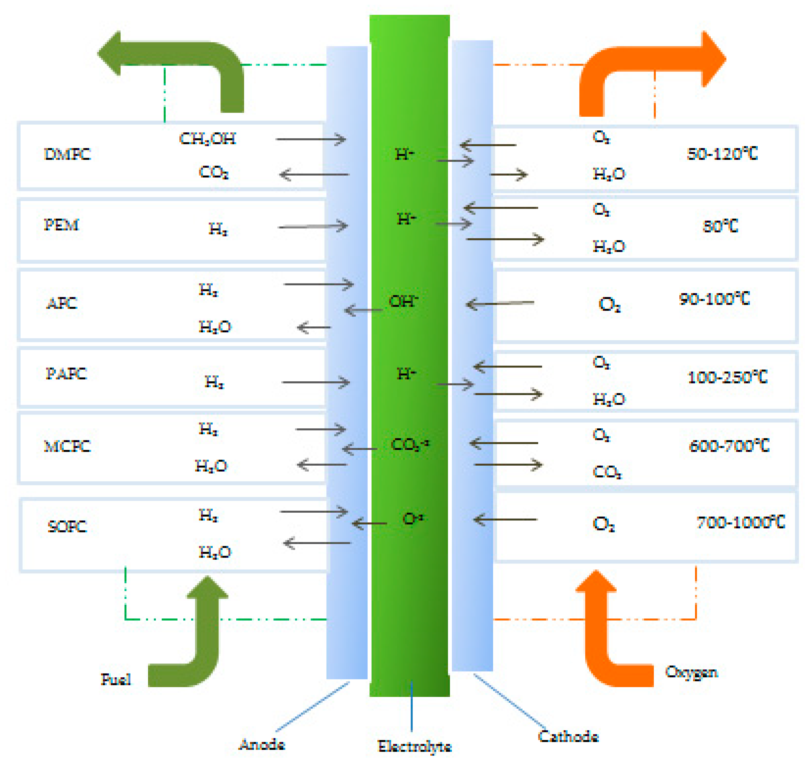
Fuel cells can be divided into six categories according to electrolyte, fuel and temperature, as shown in Figure 2 [71,76]. Alkaline fuel cells (AFC) use KOH solution as an electrolyte, which can operate at lower temperatures around 80 °C; PEMFCs and direct methanol fuel cells (DMFCs) use polymer membrane as an electrolyte to transport protons. Among them, PEMFCs use PEM and Pt as catalysts and need to work under acidic conditions [73]. The phosphoric acid fuel cell (PAFC) uses pure phosphoric acid as the electrolyte and works at 200 °C. Molten carbonate fuel cells (MCFCs) use molten carbonate as an electrolyte and the operating temperature can reach 650 °C. The solid oxide fuel cell (SOFC) uses ceramic (solid oxide) materials as the electrolyte to conduct oxygen anions from the cathode to the anode at a working temperature of 1000 °C [77]. In addition, microbial fuel cells are a new type of bioelectrochemical device which utilize a biocatalyst to convert the chemical energy stored in organic wastewater into power supply and remove pollutants while generating electricity [78]. However, microbial fuel cells have high production cost and low power density and energy conversion efficiency. The principle, electrode, catalyst, advantages and disadvantages of the fuel cells are shown in Table 2.
4.1.3. Applications of Graphene-Based Nanocomposites in Hydrogen Fuel Cells
The incorporation of GO into the PEM of HFCs can improve the proton conductivity and stability of the membrane and reduce the fuel permeability of the membrane [79]. Choi et al. [80] fabricated a GO/Nafion composite membrane and found that the methanol permeability of the Nafion membrane was greatly reduced by adding GO as a filler. Because GO is hydrophilic, it can interact with the non-polar main chain and polar ion cluster of the Nafion PEM to modify the microstructure of the hydrophilic and hydrophobic regions of PEM. Thus, the phase separation of the membrane is reduced in the presence of water molecules and the permeability of the proton exchange membrane is improved. Hu et al. [81] reported breakthroughs in the study of the proton transport characteristics of graphene-based membrane materials and found that two-dimensional nanocomposites with a single atomic layer thickness such as graphene and boron nitride could be used as good proton-conducting membranes.
HFCs mostly use precious metal as catalysts, such as Ru, Rh, Pd, Ag, Ir, Pt and Au, which are expensive. Precious metal catalytic activity can be improved and the cost can be reduced by improving the carrier type, structural constitution and surface characteristics. For example, when single-atom Rh is anchored on nitrogen-doped carbon, the strong interaction between carbon and Rh can effectively prevent the migration and aggregation of Rh metal particles and improve the stability of the catalyst [82]. Carbon-supported trimethoxy nanocomposites as fuel cell catalysts can elevate the activity of electrocatalysts and reduce the cost [83]. Graphene can complement the network of electroactive materials to buffer the change in electrode volume and prevent the breakage and aggregation of electrode materials [84,85,86,87]. Density functional theory is the powerful tool electronic structures based on first principles and has been widely used in fuel cells [88]. Mineva et al. [89] used density functional theory to study the active sites of Fe–N–C cathode catalysts for fuel cells.
4.1.4. Selection of Catalysts for Hydrogen Fuel Cells
The choice of carrier material is key to the activity, selectivity, durability and cost-effectiveness of a catalyst [79]. One of the ways to improve the performance of fuel cells is to increase the power density by reducing the membrane thickness and membrane resistance of the fuel cell [80]. Electrocatalysis is the main driving factor of the reactions between the anode and cathode sides of fuel cells, and the performance of each electrode reaction is dependent on the specific surface area of the catalyst. The ideal catalyst carrier should have the following conditions [90,91,92,93,94]:
(i) It has conductivity, or a catalyst carrier with good conductivity is used to obtain high conductivity;
(ii) It has certain chemical stability, i.e., under the conditions of achieving the target reaction, the surface of the electrocatalyst will not be inactivated prematurely due to electrochemical reactions;
(iii) The larger the surface area, the more active sites and the better the performance of the material;
(iv) Appropriate porosity is conducive to electron and proton conduction, material transmission and water discharge;
(v) The catalyst is easy to recycle, thus reducing costs and avoiding environmental pollution.
Table 2.
Overview of different types of fuel cells.
| The Reaction of Fuel Cells | Electrolyte | Catalyst | Advantages | Disadvantages | References |
|---|---|---|---|---|---|
| AFC A:2H2 + 4OH− → 4H2O + 4e− C: O2 + 2H2O + 4e− → 4OH− | Alkaline (LiOH, NaOH, KOH, CSOH) | Pt/C Pd/C AgPt/C Ag/C | Cheapest to manufacture and low-cost alkaline electrolyte | Catalyst degradation corrosion | [93] |
| PEMFC A: H2 → 2H+ + 2e− C:1/2O2 + 2H+ + 2e− → H2O | SPES/GO | A and C: rGO-Au/Pt/C GO/Pt, Pt/GNP Pt/GNT | High ion-exchange capacity, water absorption and proton conductivity of membrane | Harder composite film | [44,50] |
| PAFC A: H2 → 2H+ + 2e− C: O2 + 4H+ + 4e− → 2H2O | Phosphoric acid | Pt/GO Pt/GNP | CO2-tolerant, fuel flexibility | Low current density regions | [94] |
| SOFC A: H2 + O2− → H2O + 2e− C: 1/2O2 + 2e− → O2− | Solid oxide (BaZrO3 La2Mo2O9 BaCeO3) Ceramic | Cr | Low sensitivity, inexpensive materials | Low active fuel cells components | [62] |
4.2. The Applications of Graphene-Based Nanocomposites in Lithium-Ion Batteries
4.2.1. Lithium-Ion Batteries
LIBs belong to the category of a secondary battery (rechargeable battery), which is essentially a lithium-ion concentration difference battery [95,96]. The positive and negative electrodes are composed of two different lithium-ion intercalation compounds. When charging, lithium ions are extracted from the positive electrode compound and inserted into the lattice, and the positive electrode is in a lithium-poor state; during discharge, lithium ions are extracted from the negative electrode and inserted into the positive electrode, and the positive electrode is in a lithium-rich state. LIBs have been widely used in cell phones, hybrid electric vehicles and pure electric vehicles, unmanned aerial vehicles and satellites due to their advantages of high specific energy, high working voltage, long cycle life, no memory effect and low pollution [92,93,94,95,96,97,98,99,100].
During the charge–discharge cycle of LIBs, the deposition and exfoliation of lithium metal is usually uneven, which can lead to the growth of lithium dendrites [101]. The growth of lithium dendrites can cause instability of the electrode and electrolyte interface of the LIBs during the cycle, destroying the solid electrolyte interface film formed, and the lithium dendrites will continue to consume the electrolyte during the growth process and produce metal lithium. During the growth process of lithium dendrites, the electrolyte will be consumed continuously and lead to irreversible deposition of lithium metal, which causes a low coulomb efficiency. The formation of lithium dendrites can even pierce the diaphragm and result in internal short-circuit of a lithium-ion battery, which leads to thermal runaway of the battery and brings about combustion and explosion.
The electrode material of LIBs is mostly composed of metal ions such as nickel manganese cobalt or nickel cobalt aluminum; however, cobalt metal is scarce and expensive. With the increasingly prominent issue of energy shortage and environmental pollution, people urgently need low-cost cobalt-free batteries to get rid of the dependence of electrode materials on cobalt.
Graphene is a potential conductive agent for LIBs which has high electrical conductivity and flexible, two-dimensional, ultra-thin structural characteristics [98]. Through the "surface-point" contact mode between graphene and active materials, the low conductivity threshold of graphene allows a small amount of graphene to effectively increase the electronic conductivity of the electrode and greatly reduce the use of conductive agents as inactive materials, and this can effectively increase the volume energy density of the battery. Graphene has many applications in LIBs, as shown in Figure 3.
The solid-liquid composite electrolyte is a gel electrolyte composed of a solid polymer and a liquid electrolyte, which has high ionic conductivity, low electronic conductivity and good thermal and mechanical stability [102]. Inorganic gels can reduce the interaction between anions and cations, thereby improving the dissociation of lithium salts and enhancing the migration of lithium ions. Ceramic-graphene nanocomposites are currently tough solid electrolytes with high electrical conductivity, which can greatly solve the above problems [101].
4.2.2. Classification of Lithium-Ion Batteries
According to cathode materials, the commonly used LIBs can be divided into the following six categories: lithium nickel cobalt manganese oxide, lithium nickel cobalt aluminate, lithium iron phosphate, lithium cobalt oxide, lithium carbonate battery and lithium manganese oxide, among which nickel cobalt manganese oxide and nickel cobalt aluminate are ternary cathode materials. The electrochemical performance of lithium-ion batteries mainly depends on the structure and performance of the electrode materials and the electrolyte materials [103]. Cathode materials are not only used as electrode materials to participate in electrochemical reaction but also the source of lithium ion.
4.2.3. Applications of Graphene-Based Nanocomposites in Anodes for Lithium-Ion Batteries
As one of the main functional components of LIBs, anode materials play a vital role in the performance of LIBs. However, the theoretical capacity of industrial graphite anode is relatively low, which leads to a reduction in the energy density of LIBs; hence, using graphite as the anode of LIBs faces a clear challenge. Silicon, phosphide, metal oxide, sulfide, etc., can significantly increase the energy density of LIBs and their low cost has been extensively studied, as well as large volume change and poor cycle stability [104,105]. On the basis of these materials, composite graphene can solve the problem, e.g., cobalt sulfide’s own capacity decay, low conductivity and cyclicity, which are related to the volume expansion of the electrode, resulting in specific and capacity decays and the formation of polyazo anions [105]. Graphene blocks dissolute in electrolytes by absorbing polyazo anions on amorphous surfaces and enhance ionic conduction and improve the cycle life.
Hou et al. [106] fabricated G⊥FP@C-NA nanocomposites as the anode materials of LIBs (Figure 4). The structure of the materials was carbon-coated FeP nanorod array (FP@C-NA)grown vertically on the conductive reduced graphene oxide (G) network. Due to the unique structure of G⊥FP@C-NA, it exhibits obvious conductivity and structural stability in lithium storage. For example, this material provides high lithium storage capacity (1106 mA h g−1 at 50 mA g−1), excellent rate capability (565 mA h g−1 at 5000 mA g−1) and long-term cycle stability (1009 mA h g−1 at 500 mA g−1 after 500 cycles, 1310 mA h g−1 at 2000 mA g−1 after 2000 cycles). This attractive array structure design can also be extended to other different energy storage systems, which will promote the development of next-generation electrochemical energy storage devices with high power and high energy density.
The stacking of graphene sheets in the process of electrode preparation leads to slow ion transport and decreased surface activity, which hinders the practical application. Based on this, compared with in-plane graphene, porous graphene has the dual advantages of graphene and porous materials. Porous graphene nanosheets and interconnected nanocages have layered porous channels, fast ion transmission, complete conductive networks and good structural durability to improve the cycle stability [107,108] Zhu et al. [109] pointed out that these porous graphene nanosheets and interconnected nanocages could effectively prevent the aggregation of graphene and maintain its layered structure, which is very important for high-power battery electrodes.
Silicon has been considered as a good alternative material which can significantly increase the energy density when used as an anode material. Therefore, the energy density of a battery constructed with a silicon anode was about 25% higher than that of a commercial battery using a traditional graphite anode [105].
Han et al. [35] revealed that when using a SnO2/graphene nanocomposite as the LIB anode, the initial discharge specific capacity was as high as about 1610 mA h g−1, which could significantly improve the specific capacity of the electrode. After 100 cycles, the specific capacity remained at 87%, showing a good cycle stability. The main reason was that graphene could provide mechanical support to reduce the volume change of the SnO2 anode and prevent nanoparticle agglomeration, and it could also act as a conductive network to promote charge transfer and Li+ diffusion. The reaction mechanism was proposed according to the following equation:
SnCl2 + H2O → Sn(OH)Cl + HCl
Sn(OH)Cl + GO → SnO2/graphene + HCl
In the reaction, SnCl2 is firstly hydrolyzed to Sn(OH)Cl, and subsequently, Sn(OH)Cl is oxidized to SnO2, reducing GO to graphene under continuous ultrasonic force. It is established that two-step reactions are involved in SnO2-based electrodes:
SnO2 + 4Li+ + 4e− → Sn + 2Li2O
Sn + xLi+ + xe− → LixSn (0 ≤ x ≤ 4.4)
4.2.4. Applications of Graphene-Based Nanocomposites in Cathodes for Lithium-Ion Batteries
Among the various components involved in LIBs, cathodes currently limit the energy density and dominate the batteries’ cost [110]. Lithium transition metal phosphates or oxides are used as cathode materials for LIBs, e.g., LiFePO4 or LiCO2 [106,110,111]. Venkateswara et al. [112] showed the results of using a lithium transition metal oxide (LiNi1/3Co1/3Mn1/3O2) as a cathode for the second generation of LIBs, which faced capacity fading. Graphene is incorporated into these materials to obtain a higher charge–discharge rate and capacity retention rate [103]. Graphite materials instead of lithium-containing transition metal oxides as cathodes of LIBs can reduce the overall cost and potential environmental pollution [113].
Wang et al. [107] used density functional theory to study a high-carbon acyl C6O6 molecular functionalized graphene electrode as an LIB cathode. Binding energy calculations revealed that C6O6 molecules maintain good electronic conductivity after being adsorbed on graphene by physical adsorption. The reduced voltage of the C6O6@graphene cathode was between 1.5 and 2.6 V, and the energy density was about 155 mA h g−1, which is a promising renewable electrode material. Lee et al. [114] demonstrated that Na2C6O6, as the cathode of the battery, had an energy density of 726 Wh kg−1, an energy efficiency above 87% and a good cycle retention, and the storage of tetrasodium in the Na2C6O6 electrode was realized.
Vanadium pentoxide has limitations such as insufficient electronic conductivity, sluggish ion diffusion and volume expansion. In order to solve these problems, Nakhanivej et al. [115] demonstrated spray-frozen assembly into hierarchically structured open porous vanadium pentoxide/reduced GO composite microballs for high-performance LIB cathodes. When the current density increases from 100 to 1000 mA h g−1, the capacity retention of vanadium pentoxide/reduced GO composite microballs is about 51.3%, which is much greater than that of vanadium pentoxide particles (36.4%). The capacity retention of 80.4% with a coulombic efficiency of 97.1% over 200 cycles is two times greater than that of V2O5 particles, indicating improved cycle stability.
4.3. The Applications of Graphene-Based Nanocomposites in Solar Cells
4.3.1. Solar Cells
Solar cells are devices that convert light energy into electrical energy directly through photoelectric or photochemical effects, which are usually called photovoltaic cells [116]. Solar cells have become the focus of attention due to high efficiency, long-term stability and low cost.
4.3.2. Classification of Solar Cells
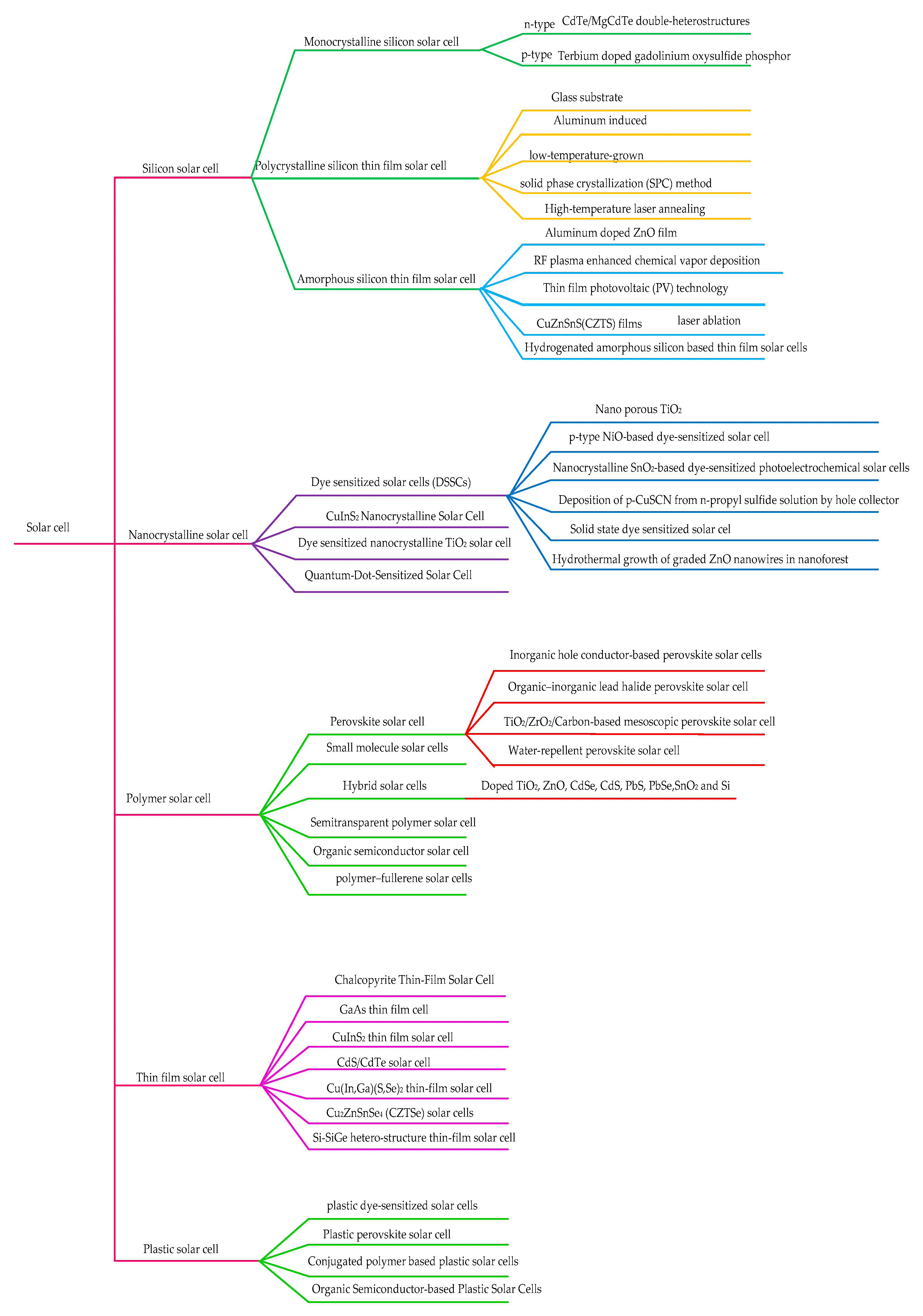
According to different materials, solar cells are divided into crystalline silicon solar cell, multiple compound thin-film solar cells, polymer multilayer modified electrode solar cells, nanocrystalline solar cells, organic solar cells and plastics solar cells. Among them, crystalline silicon solar cells are the first generation of solar cells and are currently the most mature [117]. These are divided into monocrystalline silicon solar cells and polycrystalline silicon solar cells. The structure of monocrystalline silicon solar cells is mainly p-n junction. Second-generation solar cells mainly refer to thin-film solar cells, represented by copper indium gallium selenium films and cadmium telluride (CdTe) films (Figure 5) [118,119]. Emerging solar cells include dye-sensitized cells, organic solar cells, perovskite solar cells and quantum dot (QD) solar cells [120,121]. Additionally, plastics solar cells have simple production processes, low energy consumption and low cost and the materials can be degraded, which is green and environmentally friendly products.
4.3.3. The Applications of Graphene-Based Nanocomposites in Solar Cells
As a new type of material, graphene has been used for transparent electrodes of solar cells and electron acceptor materials in solar cells. The application of graphene in solar cells is analyzed to provide theoretical support for the continuous research on new materials and technologies and will effectively promote the overall development of the new energy industry.
Dye-sensitized solar cells as third-generation photovoltaic cells are a new generation of non-silicon-based solar cells, which mainly use nano-TiO2 and photosensitive dye as raw materials to simulate the photosynthesis of plants in nature and convert solar energy into electricity [104,120,121,122,123]. Cheng et al. [124] reported that the conversion efficiency of TiO2@rGO hybrids was higher than that of TiO2 (4.78%). Kavan et al. [122] revealed that the energy conversion efficiency of dye-sensitized solar cells with three-dimensional honeycomb graphene pair electrode has reached up to 7.8%.
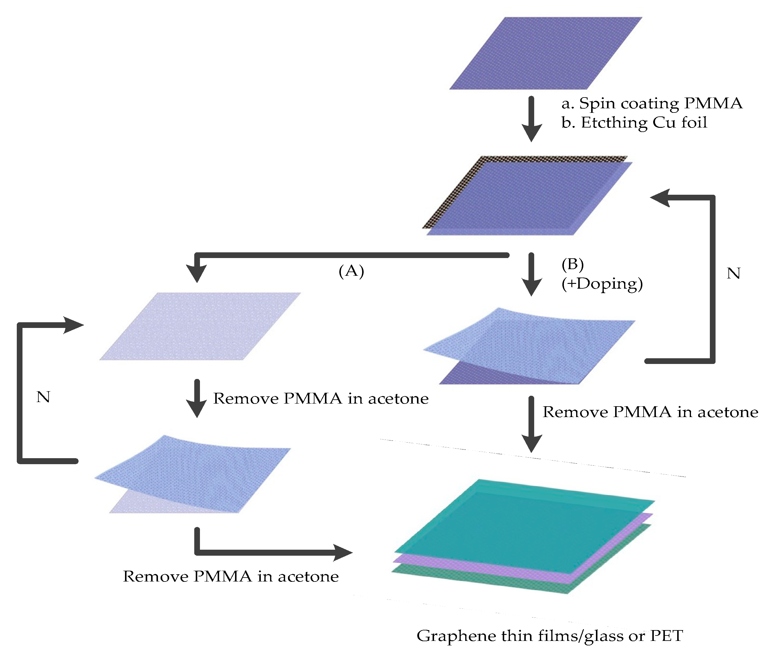
Few layers of graphene/n-Si Schottky junction solar cells can further improve the energy conversion efficiency [124,125]. However, this material is highly difficult to prepare and thus its practical application is clearly limited [126]. Sun et al. [127] reported that N-layer graphene can be obtained without any organic impurities between the layers. After the Cu (or Ni) foil is etched, the two-layer graphene film is directly transferred to the third layer of graphene on the Cu (or Ni) foil, thereby forming a three-layer graphene film. Finally, the multilayer graphene can be transferred to other substrates and the polymethylmethacrylate (PMMA) acetone on the top can be removed, as shown in Figure 6.
In 2018, Li et al. [128] introduced the self-doping process of the graphene-silicon Schottky junction induced by steam oxidation of HNO3. The p-type self-doping of graphene oxide with HNO3 enhanced the intrinsic potential and conductivity, thus increasing the charge transfer and inhibiting the carrier recombination at the graphene-silicon Schottky junction. After HNO3 oxidation treatment, the open circuit voltage increased from 0.36 to 0.47 V, the short-circuit current increased from 0.80 to 7.71 μA, and the ideal coefficient was optimized from 4.4 to 1.0. The enhanced performance of graphene-silicon solar cells was due to the oxidation-induced p-type self-doping of the graphene-silicon junction.
Organic photovoltaic (OPV) cells use photosensitive organics as semiconductor materials and generate voltage to form current through the photovoltaic effect [129]. Solar cells have the advantages of low manufacturing cost, light weight, strong versatility and ease of use. Graphene and its derivatives can be used as interface materials in organic solar cells, e.g., transparent electrode, active layer, interface layer and counter electrode [130,131]. Lee et al. [132] functionalized GO with (3-glycidoxypropyl) trimethoxysilane (GPTMS) and triethoxymethylsilane (MTES) to obtain GPTMS-sGO and MTES-sGO. The power conversion efficiency (PCE) values of OPV batteries of GPTMS-sGO and MTES-sGO are 3.00% and 3.08%, respectively. The PCE value is a measure of the ability of solar cells to convert light energy into electrical energy and is determined by the short-circuit current density and filling coefficient.
Perovskite solar cells (PSCs) are solar cells using perovskite-type organic metal halide semiconductors as light absorbing materials, which are considered as one of the most promising power-generating pieces of equipment in the future [133]. Two-dimensional-type PSCs have obvious long-term stability and are more suitable for application. Graphene and its derivatives have environmental stability and compactness, and their multi-functional groups can modify perovskite films and the interface layers of devices. Liu et al. [134] prepared 2D PSCs with dimethylformamide (DMF) and γ-butyrolactone (GBL) as precursor solvents. The results show that the GBL-treated 2D PSC shows better quality, less pinholes and higher crystallinity, and the PCE is 11.17%, which is significantly higher than that of the DMF-treated devices. Meanwhile, the open-circuit voltage and short-circuit current density are improved, with stable current output and negligible hysteresis. Redondo Obispo et al. [135] studied graphene doping in the poly(3,4-ethylene dioxythiophene)/poly (styrene sulfonate) PEDOT/PSS as the hole extraction layer (HTL) of inverted perovskite solar cells. The results showed that the conductivity of the PEDOT/PSS layer was improved by adding graphene, and the PCE of the solar cell was increased by 33%. This was likely to be caused by the increased conductivity of graphene-doped PEDOT/PSS, which could improve the charge collection efficiency.
Graphene plays a role in the front and back buffer layers in copper (In, Ga) (S, Se) materials for thin-film solar cells; for instance, Kur transmittance and higher thermal stability [136]. The nano layer has some functions, e.g., reducing the consumption of aluminum and the cost of deposition, which offer high conductivity and transmittance. The conductive metal contact material can be controlled by changing the number of graphene layers. In addition, a highly conductive three-dimensional graphene network is introduced at the contact between the CdS/CdTe interface and the back of the CdS/CdTe thin-film solar cells and the conversion efficiency is improved.
4.4. The Applications of Graphene-Based Nanocomposites in Thermoelectric Conversion
4.4.1. Thermoelectric Conversion
Thermoelectric conversion realizes the direct output of heat energy to electric energy [137]. A thermoelectric power generation device is a basic thermoelectric power generation unit that realizes electric energy output. Thermoelectric devices have the advantages of long service life, no noise and environmental friendliness, and they can be integrated in various components and have a certain flexibility. Thermoelectric conversion is a type of green energy which is mostly used in waste heat recovery in aerospace, aviation and civil industries [138].
Thermoelectric materials mainly include inorganic and organic polymer materials. Inorganic thermoelectric materials comprise Bi2Te3-, SiGe-, Al2O3- and CoSb3-based materials, and organic polymer thermoelectric materials primarily comprise polyaniline, PEDOT, polypyrrole and polythiophene [103,139]. Organic polymer thermoelectric materials are basically composed of conductive polymers and their inorganic filler composites. Graphene is also considered as a promising thermoelectric material because of its intrinsic ultra-high conductivity and moderate Seebeck coefficient [103]. The thermal conductivity can be effectively improved by combining carbon materials with organic polymer materials with low thermal conductivity [140].
4.4.2. Classification of Thermoelectric Materials
According to their operating temperature, thermoelectric materials can be divided into three categories [103]. (a) Bismuth telluride and its alloy: this material is widely used in thermoelectric coolers, and its optimum operating temperature is lower than 450 ℃; (b) lead telluride and its alloys: they are widely used in thermoelectric generators, and their optimum operating temperature is about 1000 ℃; (c) Si-Ge alloy: this kind of material is also used in thermoelectric generators, and its optimum operating temperature is about 1300 °C.
4.4.3. The Applications of Graphene-Based Nanocomposites in Thermoelectric Materials
The excellent thermoelectric materials should have higher electric conductivity and lower thermal conductivity, while the intrinsic graphene electron mobility can improve the conductivity of the materials. Although the thermal conductivity of graphene is excellent, graphene can reduce the lattice thermal conductivity of thermoelectric materials by embedding itself into the matrix of traditional thermoelectric materials, thereby obtaining new composite thermoelectric materials with high energy conversion efficiency [141].
Chen et al. [142] reported the radiative heat and photothermoelectric conversion characteristics of three-dimensional microporous graphene excited by a terahertz wave. Due to the rich chemical modification and band gap regulation properties of three-dimensional graphene, oxygen-containing functional group evolution and carrier type transition could occur through high-temperature treatment. Meanwhile, three-dimensional microporous graphene has a pore size equivalent to the terahertz wavelength, so the incident terahertz wave is completely absorbed, which can increase the temperature gradient of the device and improve the sensitivity of terahertz detectors. Feng et al. [143] reported a graphene/CoSb3 composite thermoelectric material that was prepared by the chemical method and sintering process. When the temperature was 800 K, the ZTmax of the graphene-based nanocomposite was 0.6, which was 1.3 times higher than that of CoSb3.
5. Assessment Methods for Four Clean Energy Sources
Performance evaluation methods of graphene-based nanocomposites in the applications of clean energy materials have gradually become a research focus. This section uses mathematical models to assess the performance of hydrogen fuel cells, lithium-ion batteries, solar cells and thermoelectric materials.
5.1. Assessment of Hydrogen Fuel Cells
The Scherer equation (Equation (8)) is used to calculate the average crystallite size of graphene-based nanocomposites by using planes from XRD data.
where d is the average particle size (nm); B2 is the full width of the diffraction peak at half maximum in radians; λ denotes the wavelength and stands for the angle at the position of the peak maximum [144].
The ion-exchange capacity (IEC) of a film was determined using a titration method. At first, the dried membrane was put into 1.0 M HCl for 24 h, washed with distilled water several times and dried in a vacuum oven at 50 °C for 24 h. Then, the above-mentioned dried film was immersed in 1.0 M NaCl solution for 24 h [25]. Finally, phenolphthalein was added as a pH indicator and titrated with 0.01 M NaOH standard solution, and the meq/g value of IEC was obtained by Equation (9):
Water uptake of a membrane is calculated using Equation (10):
where W1 and W2 are the mass of the wet membrane after immersion in demineralized water for 24 h and the mass of the dry membrane after drying in an oven at 100 °C for 24 h, respectively.
In order to obtain the resistance of a film, the proton conductivity σ (s/cm) of the membrane is calculated using the following Equation (11):
where L is the thickness of the membrane (cm); R is the resistance of the membrane (Ω) and A denotes the surface area of the membrane (cm2). The membrane resistance is measured by electrochemical impedance spectroscopy [145]. The equivalent circuit is fitted to a diagram using software, and the resistance of the film is obtained.
Methanol permeability is calculated from the slope of the graph between diffusion time and methanol concentration by the following equation (12):
where CA and CB are the concentrations of methanol on side A and side B, respectively; A is the area of the membrane; L denotes the thickness of the membrane; VB is volume of the cells in side B and D and K are the methanol diffusion and partition coefficient, respectively [146].
The product of DK is membrane methanol permeability (P), the methanol concentration on side B increases linearly with the increase of permeation time [147]. P can be calculated by the Equation (13):
where m is the slope of CB (T) linear graph.
The membrane characteristics required for high performance of fuel cells are high proton conductivity and low methanol permeability [43]. The membrane performance is calculated by the Equation (14):
where Φ is a selectivity parameter, σ is the ionic conductivity and P is the methanol permeability.
5.2. Assessment of Lithium-Ion Batteries
5.3. Assessment of Solar Cells
There are three steps in the photovoltaic conversion process of most solar cells [150,151]. (a) Light is absorbed and generated electron-hole pairs in the semiconductor layer; (b) electrons and holes is separated by the built-in electric field in the junction area; (c) a small amount of carriers are extracted to the external electrode [152,153]. The difference between the two types of junctions is the size of the built-in electric field and the height of the barrier, which are closely related to the rate of hole/electron separation and recombination. A steady progress has been made in hybrid graphene/silicon Schottky solar cells based on unconventional Schottky Junctions, and the calculation of power conversion efficiency of hybrid graphene/silicon Schottky solar cells is shown in Table 4 [154].
In crystalline silicon solar cells, increasing minority carrier lifetime is the key to improve the efficiency of solar cells [145]. The minority carrier lifetime is related to the diffusion length of crystalline silicon solar cells, typically the diffusion length is 100–300 μm. The minority carrier lifetime is calculated with the Equation (15):
where L is the diffusions length in meters; D is the diffusivity in m2/s and τ denotes the lifetime in seconds.
5.4. Assessment of Thermoelectric Materials
The conversion efficiency of thermoelectric module is determined by Carnot efficiency, which is calculated by Equation (16):
where Thot is the hot-side temperature; Tcold denotes the cold-side temperature; Tm represents the average temperature [137]; ZT is the thermoelectric figure-of-merit. ZT is calculated by the Equation (17):
where S, σ, kL, ke, and T are the seebeck coefficient, electrical conductivity, lattice thermal conductivity, electronic thermal conductivity and absolute temperature, respectively [76]. Temperature difference (Thot – Tcold) and the improvements in thermoelectric conversion efficiency entirely relied upon the ZT enhancement.
6. Summary and Future Perspectives
This paper reviews the applications of graphene-based nanocomposites in hydrogen fuel cells, lithium-ion batteries, solar cells and thermoelectric conversion, as well as their evaluation methods. Moreover, the preparation and characterization of graphene-based composites are introduced.
There are some research interests in graphene-based nanocomposites used in energy devices, which have been proven to be suitable for the development of basic materials for alternative energy sources; for example, (a) in hydrogen fuel cells, graphene is used as an electrode material to enhance electrocatalytic activity; (b) in lithium-ion batteries, graphene-based nanocomposites show better performance as they have high power density and energy density and a fast charging speed; (c) in solar cells, graphene-based composites are used in photovoltaic devices because of their unique characteristics of high carrier mobility and low resistivity, transmittance and filling two-dimensional networks, which improves the power conversion efficiency; (d) in thermoelectric materials, graphene-based nanocomposites with a polycrystalline structure can achieve high-efficiency thermoelectric energy conversion. Currently, in Ningxia, China, commercial production of graphene version 3.0 has started, with an annual output of 2000 tons of graphene-modified conductive paste (20 tons of graphene). In terms of power distribution, AI will be a core part of future smart grids; this technology will continue to collect and integrate data from millions of smart sensors so that decisions can be made in a timely manner to allocate energy resources in the best way to realize complementary, stable, safe, economic and efficient clean energy systems of water, wind, light and storage. In order to gain further knowledge to accelerate the development of this field, we hope that this review can provide a valuable reference for future research.
Author Contributions
Conceptualization and funding acquisition, J.H.; writing—review and editing, Y.X. and J.H.; Literature search, L.X. and C.L.; Drawing, J.Q. and Y.H.; supervision, X.W. All authors have read and agreed to the published version of the manuscript.
Funding
This work was funded by the Government of Guizhou Province (Project No. [2017] 5726-42), the National 111 Project of China under Grant No. D17016, and the APC was funded by the National Natural Science Foundation of China under Grant No. 21667012.
Conflicts of Interest
The authors declare no conflict of interest.
References
- Filote, C.; Felseghi, R.A.; Raboaca, S.M.; Achilean, I. Environmental impact assessment of green energy systems for power supply of electric vehicle charging station. Int. J. Energ. Res. 2020, 44, 10471–10494. [Google Scholar]
- Ma, S.; Zhou, H.C. Gas storage in porous metal-organic frameworks for clean energy applications. Chem. Commun. 2010, 46, 44–53. [Google Scholar] [CrossRef] [PubMed]
- Sahoo, N.G.; Pan, Y.; Li, L.; Chan, S.H. Graphene-based materials for energy conversion. Adv. Mater. 2012, 24, 4203–4210. [Google Scholar] [CrossRef] [PubMed]
- Hu, C.; Liu, D.; Xiao, Y.; Dai, L. Progress in natural science. Met. Mater. Int. 2018, 28, 121–132. [Google Scholar]
- Higgins, D.; Zamani, P.; Yu, A.; Chen, Z. The application of graphene and its composites in oxygen reduction electrocatalysis: A perspective and review of recent progress. Eerg. Envion. Sci. 2015, 9, 357–390. [Google Scholar]
- Tahir, M.; Pan, L.; Idrees, F.; Zhang, X.; Wang, L.; Zou, J.J.; Wang, Z.L. Electrocatalytic oxygen evolution reaction for energy conversion and storage: A comprehensive review. Nano Energy 2017, 37, 136–157. [Google Scholar] [CrossRef]
- Thimmappa, R.K.; Gautam, M.; Devendrachari, M.C.; Kottaichamy, A.R.; Thotiyl, M.O. Proton conducting graphene membrane electrode assembly for high performance hydrogen fuel cell. ACS Sustain. Chem. Eng. 2019, 7, 14189–14194. [Google Scholar]
- Wang, S.; Zhao, W.; Xie, L.; Cao, H.; Huang, W. Solution-processable GO/RGO: Preparation, functionalization, self-assembly and applications in smart information devices. Chin. Sci. Bull. 2019, 64, 2689–2702. [Google Scholar] [CrossRef]
- Elmekawy, A.; Hegab, H.M.; Losic, D.; Saint, C.P.; Pant, D. Applications of graphene in microbial fuel cells: The gap between promise and reality. Renew. Sust. Energ. Rev. 2016, 72, 1389–1403. [Google Scholar]
- Jankovský, O.; Nováček, M.; Luxa, J.; Sedmidubský, D.; Boháčová, M.; Pumera, M.; Sofer, Z. Concentration of nitric acid strongly influences chemical composition of graphite oxide. Chem.-Eur. J. 2017, 23, 6432–6440. [Google Scholar]
- Mahmood, N.; Zhang, C.; Yin, H.; Hou, Y. Graphene-based nanocomposites for energy storage and conversion in lithium batteries, supercapacitors and fuel cells. J. Mater. Chem. A 2014, 2, 15–32. [Google Scholar] [CrossRef] [Green Version]
- Cao, Y.; Fatemi, V.; Fang, S.; Watanabe, K.; Taniguchi, T.; Kaxiras, E. Unconventional superconductivity in magic-angle graphene superlattices. Nature 2018, 556, 43–52. [Google Scholar] [CrossRef] [PubMed]
- Cao, Y.; Fatemi, V.; Demir, A.; Fang, S.; Tomarken, S.L.; Luo, J.Y. Correlated insulator behaviour at half-filling in magic angle graphene superlattices. Nature 2018, 556, 80–84. [Google Scholar] [CrossRef] [PubMed]
- Yue, X.; Huang, S.L.; Cai, J.J.; Jin, Y.; Shen, P.K. Heteroatoms dual doped porous graphene nanosheets as efficient bifunctional metal-free electrocatalysts for overall water-splitting. J. Mater. Chem. A 2017, 5, 7784–7790. [Google Scholar]
- Guan, J.; Duan, Z.; Zhang, F.S.; Kelly, D.; Si, R.; Dupuis, M. Water oxidation on a mononuclear manganese heterogeneous catalyst. Nat. Catal. 2018, 1, 870–877. [Google Scholar]
- Gyumin, L.; Kenneth, K.; Hong, K.; Woorim, L.; Kyung, P. Enhanced thermoelectric conversion efficiency of CVD graphene with reduced grain sizes. Nanomaterials 2018, 8, 557. [Google Scholar]
- Qi, J.M.; Hou, Y.; Hu, J.W.; Ruan, W.Q.; Xiang, Y.Q.; Wei, X.H. Decontamination of methylene blue from simulated wastewater by the mesoporous rGO/Fe/Co nanohybrids: Artificial intelligence modeling and optimization. Mater. Today Commun. 2020, 24, 100709–100724. [Google Scholar] [CrossRef]
- Fan, M.Y.; Hu, J.W.; Cao, R.S.; Xiong, K.N.; Wei, X.H. Modeling and prediction of copper removal from aqueous solutions by nZVI/rGO magnetic nanocomposites using ANN-GA and ANN-PSO. Sci. Rep. 2017, 7, 18040–18054. [Google Scholar] [CrossRef] [Green Version]
- Ai, W.; Zhou, W.; Du, Z.; Sun, C.; Yang, J.; Chen, Y. Toward high energy organic cathodes for Li-ion batteries: A case study of vat dye/graphene composites. Adv. Funct. Mater. 2017, 27, 1603604–16036012. [Google Scholar] [CrossRef]
- Tiwari, J.N.; Tiwari, R.N.; Kim, K.S. Zero-dimensional, one-dimensional, two-dimensional and three-dimensional nanostructured materials for advanced electrochemical energy devices. Prog. Mater. Sci. 2012, 57, 724–803. [Google Scholar] [CrossRef]
- Yap, K.L.; Liu, W.W. Exfoliation of charcoal by electrochemical method to synthesize few layers graphene sheets. IOP Conf. Ser. Mater. Sci. Eng. 2020, 920, 12019–12027. [Google Scholar] [CrossRef]
- Khan, A.; Habib, M.R.; Kumar, R.R.; Islam, S.M.; Arivazhagan, V.; Salman, M.; Yang, D.; Yu, X.G. Wetting behaviors and applications of metal-catalyzed CVD grown graphene. J. Mater. Chem. A 2018, 6, 22437–22464. [Google Scholar] [CrossRef]
- Green, A.A.; Hersam, M.C. Emerging methods for producing monodisperse graphene dispersions. J. Phys. Chem. Lett. 2010, 1, 544–549. [Google Scholar] [CrossRef] [PubMed] [Green Version]
- Li, X.; Shen, J.; Wu, C.; Wu, K. Ball-mill-exfoliated graphene: Tunable electrochemistry and phenol sensing. Small 2019, 15, e1805567. [Google Scholar] [CrossRef] [PubMed]
- Elshof, J.E.T.; Yuan, H.; Rodriguez, P.G. Two-dimensional metal oxide and metal hydroxide nanosheets: Synthesis, controlled assembly and applications in energy conversion and storage. Adv. Energy Mater. 2016, 6, 1600355. [Google Scholar] [CrossRef]
- Behabtu, N.; Lomeda, J.R.; Green, M.J.; Higginbotham, A.L.; Sinitskii, A.; Kosynkin, D.V.; Tsentalovich, D.; Parra-Vasquez, A.N.G.; Schmidt, J.; Kesselman, E.; et al. Spontaneous high-concentration dispersions and liquid crystals of graphene. Nat. Nanotechnol. 2010, 5, 406–411. [Google Scholar]
- Jiang, L.; Fan, Z. Design of advanced porous grapheme materials: From graphene nanomesh to 3D architectures. Nanoscale 2014, 6, 1922–1945. [Google Scholar] [CrossRef]
- Ruan, W.Q.; Hu, J.W.; Qi, J.M.; Hou, Y.; Cao, R.S.; Wei, X.H. Removal of crystal violet by using reduced-graphene-oxide-supported bimetallic Fe/Ni nanoparticles (rGO/Fe/Ni): Application of artificial intelligence modeling for the optimization process. Materials 2018, 11, 865. [Google Scholar] [CrossRef] [Green Version]
- Hou, Y.; Qi, J.M.; Hu, J.W.; Xiang, Y.Q.; Xin, L.; Wei, X.H. Mesoporous Mn-Doped Fe nanoparticle-modified reduced graphene oxide for ethyl violet elimination: Modeling and optimization using artificial intelligence. Processes 2020, 8, 488. [Google Scholar] [CrossRef]
- Fan, M.Y.; Hu, J.W.; Cao, R.S.; Ruan, W.Q.; Wei, X.H. A review on experimental design for pollutants removal in water treatment with the aid of artificial intelligence. Chemosphere 2018, 200, 330–343. [Google Scholar] [PubMed]
- Shi, X.D.; Ruan, W.Q.; Hu, J.W.; Fan, M.Y.; Cao, R.S.; Wei, X.H. Optimizing the removal of Rhodamine B in aqueous solutions by reduced graphene oxide-supported nanoscale zerovalent iron (nZVI/rGO) using an artificial neural network-genetic algorithm (ANN-GA). Nanomaterials 2017, 7, 134. [Google Scholar] [CrossRef] [PubMed] [Green Version]
- Chang, W.C.; Tseng, T.C.; Yu, W.C.; Lan, Y.Y.; Ger, M.D. Graphene/ZnO nanoparticle composite photoelectrodes for Dye-Sensitized solar cells with enhanced photovoltaic performance. J. Nanosci. Nanotechnol. 2016, 16, 9160–9165. [Google Scholar] [CrossRef]
- Tan, S.M.; Pumera, M. Electrosynthesis of bifunctional WS3−x/Reduced graphene oxide hybrid for hydrogen evolution reaction and oxygen reduction reaction electrocatalysis. Chemistry 2017, 23, 8510–8519. [Google Scholar] [CrossRef] [PubMed]
- Zhang, J.; Zhou, Y.; Zheng, G.; Huang, Q.; Zheng, X.; Liu, P.; Guan, X. Novel assembly and electrochemical properties of anatase TiO2-graphene aerogel 3D hybrids as lithium-ion bateries anodes. Chem. Phys. Lett. 2016, 662, 214–220. [Google Scholar] [CrossRef]
- Han, X.; Li, R.; Qiu, S.; Zhang, X.; Zhang, Q.; Yang, Y. Sonochemistry-enabled uniform coupling of SnO2 nanocrystals with graphene sheets as anode materials for lithium-ion batteries. RSC Adv. 2019, 9, 5942–5947. [Google Scholar] [CrossRef] [Green Version]
- Ma, Y.; Bai, D.; Hu, X.; Ren, N.; Gao, W.; Chen, S. Robust and antibacterial polymer/mechanically exfoliated graphene nanocomposite fibers for biomedical applications. ACS Appl. Mater. Interface 2018, 10, 3002–3010. [Google Scholar] [CrossRef]
- Ding, Z.; Li, F.; Wen, J.L. Gram—scale synthesis of single—crystalline graphene quantum dots derived from lignin biomass. Green Chem. 2018, 20, 1383–1390. [Google Scholar] [CrossRef]
- Chen, X.; Yang, H.; Wu, B.; Wang, L.F.; Fu, Q.; Liu, Y.Q. Epitaxial growth of h-BN on templates of various dimensionalities in h-BN-graphene material systems. Adv. Mater. 2019, 1805582–1805591. [Google Scholar]
- Jo, S.S. Chemical vapor deposition (CVD) growth and optimal transfer processes for graphene. Mass. Inst. Technol. 2018, 3–50. [Google Scholar]
- Han, D.; Wang, X.; Zhao, Y.; Chen, Y.; Tang, M.; Zhao, Z. High-quality graphene synthesis on amorphous SiC through a rapid thermal treatment. Carbon 2017, 124, 105–110. [Google Scholar] [CrossRef]
- Peng, Y.; Cao, J.; Yang, J.; Yang, W.; Liu, Z. Laser assisted solution synthesis of high performance graphene supported electrocatalysts. Adv. Funct. Mater. 2020, 30, 2001756. [Google Scholar] [CrossRef]
- Vio, L.; Martelat, B.; Isnard, H.; Nonell, A.; Chartier, F. Multi-elemental Nd, Sm, Eu, Gd isotope ratio measurements by stop-flow isotachophoresis coupled to MC-ICPMS. Talanta 2018, 176, 582–588. [Google Scholar] [CrossRef] [PubMed]
- Fan, M.Y.; Li, T.J.; Hu, J.W.; Cao, R.S.; Wei, X.H.; Shi, X.D.; Ruan, W.Q. Artificial neural network modeling and genetic algorithm optimization for cadmium removal from aqueous solutions by reduced graphene oxide-supported nanoscale Zero-Valent Iron (nZVI/rGO) composites. Materials 2017, 10, 544. [Google Scholar] [CrossRef] [PubMed]
- Devrim, Y.; Arıca, E.D.; Albostan, A. Graphene based catalyst supports for high temperature PEM fuel cell application. Int. J. Hydrog. Energy 2018, 43, 11820–11829. [Google Scholar] [CrossRef]
- Iqbal, M.A.; Liaqat, A.; Hussain, S.; Wang, X.S.; Tahir, M.; Urooj, Z.; Xie, L.M. Ultralow-transition-energy organic complex on graphene for high-performance shortwave infrared photodetection. Adv. Mater. 2020, 32, 2002628–2002635. [Google Scholar] [CrossRef]
- Feng, Y.; Zhang, H.; Zhang, Y.; Qu, X. C–s bonds in sulfur-embedded graphene, carbon nanotubes, and flake graphite cathodes for lithium–sulfur batteries. ACS Omega 2019, 4, 16352–16359. [Google Scholar] [CrossRef] [Green Version]
- Muthumeenal, A.; Saraswathi, M.S.A.; Rana, D.; Nagendran, A. Fabrication and electrochemical properties of highly selective SPES/GO composite membranes for direct methanol fuel cells. J. Environ. Cem. Eng. 2017, 5, 3828–3833. [Google Scholar] [CrossRef]
- Li, P.; Yang, M.C.; Liu, Y.J.; Qin, H.S.; Liu, J.R.; Xu, Z.; Liu, Y.L.; Meng, F.X.; Lin, J.H.; Wang, F.; et al. Continuous crystalline graphene papers with gigapascal strength by intercalation modulated plasticization. Nat. Commun. 2020, 11, 2645–2655. [Google Scholar] [CrossRef]
- Tavakkoli, M.; Flahaut, E.; Peljo, P.; Sainio, J.; Kauppinen, E.I. Mesoporous single-atom-doped graphene‒carbon nanotube hybrid: Synthesis and tunable electrocatalytic activity for oxygen evolution and reduction reactions. ACS Catal. 2020, 10, 4647–4658. [Google Scholar] [CrossRef] [Green Version]
- Zhu, H.; He, R.; Mao, J.; Zhu, Q.; Li, C.; Sun, J.; Ren, W.Y.; Wang, Y.M.; Liu, Z.H.; Tang, Z.J.; et al. Discovery of ZrCoBi based half Heuslers with high thermoelectric conversion efficiency. Nat. Commun. 2018, 9, 2497. [Google Scholar] [CrossRef]
- Wang, L.F.; Liu, L.; Chen, J.; Mohsin, A.; Yum, J.H.; Hudnall, T.W.; Bielawski, C.W.; Rajh, T.; Bai, X.; Gao, S.P.; et al. Synthesis of honeycomb-structured beryllium oxide via graphene liquid cells. Angew. Chem. Int. Edit. 2020, 59, 15734–15740. [Google Scholar] [CrossRef] [PubMed]
- Zhang, W.; Xu, C.; Ma, C.; Li, G.; Wang, Y.; Zhang, K. Nitrogen-superdoped 3d graphene networks for high-performance supercapacitors. Adv. Mater. 2017, 29, 1701677–1701686. [Google Scholar] [CrossRef] [PubMed]
- Calovi, M.; Callone, E.; Ceccato, R.; Deflorian, F.; Rossi, S.; Sandra, D. Effect of the organic functional group on the grafting ability of trialkoxysilanes onto graphene oxide: A combined NMR, XRD, and ESR study. Materials 2019, 12, 3828. [Google Scholar] [CrossRef] [PubMed] [Green Version]
- Xiong, Y.F.; Liao, Q.B.; Huang, Z.; Huang, X.; Ke, C.; Zhu, H.T.; Dong, C.Y.; Wang, H.S.; Xi, K.; Zhan, P.; et al. Ultrahigh responsivity photodetectors of 2D covalent organic frameworks integrated on graphene. Adv. Mater. 2020, 32, 1907242–1907250. [Google Scholar]
- Zhang, E.; Jia, X.X.; Wang, B.; Wang, J.; Yu, X.Z.; Lu, B.G. Carbon Dots@rGO paper as freestanding and flexible potassium-ion batteries anode. Adv. Sci. 2020, 7, 2000470–2000478. [Google Scholar] [CrossRef]
- Wang, L.; Sofer, Z.; Pumera, M. Catalytic hydrogen evolution reaction on “metal-free” graphene: Key role of metallic impurities. Nanoscale 2019, 11, 11083–11085. [Google Scholar] [CrossRef]
- Tang, X.; Wen, G.; Song, Y. Stable silicon/3D porous N-doped graphene composite for lithium-ion battery anodes with self-assembly. Appl. Surf. Sci. 2018, 436, 398–404. [Google Scholar]
- Cheng, D.; Wu, P.; Wang, J.; Tang, X.; An, T.; Zhou, H. Synergetic pore structure optimization and nitrogen doping of 3D porous graphene for high performance lithium sulfur battery. Carbon 2019, 143, 869–877. [Google Scholar] [CrossRef]
- Gao, Z.; Zhu, J.; Rajabpour, S.; Joshi, K.; Li, X. Graphene reinforced carbon fibers. Sci. Adv. 2020, 6, 4191–4215. [Google Scholar] [CrossRef] [Green Version]
- Yuan, G.; Lin, D.; Wang, Y.; Huang, X.; Gao, L. Proton-assisted growth of ultra-flat graphene films. Nature 2020, 577, 204–208. [Google Scholar] [CrossRef]
- Wang, K.; Yang, L.; Wei, W.; Zhang, L.; Chang, G. Phosphoric acid-doped poly (ether sulfone benzotriazole) for high-temperature proton exchange membrane fuel cell applications. J. Membr. Sci. 2018, 549, 23–27. [Google Scholar] [CrossRef]
- Ali, M.; Riaz, R.; Anjum, A.S.; Sun, K.C.; Ko, M.J. Graphene quantum dots induced porous orientation of holey graphene nanosheets for improved electrocatalytic activity. Carbon 2020, 171, 493–506. [Google Scholar] [CrossRef]
- Wang, Y.; Zhang, Y.; Wang, G.; Shi, X.; Qiao, Y.D.; Liu, J.; Liu, H.; Ganesh, A.; Li, L. Direct graphene-carbon nanotube composite ink writing all-solid-state flexible microsupercapacitors with high areal energy density. Adv. Funct. Mater. 2020, 30, 1907284–1907293. [Google Scholar] [CrossRef]
- Zhang, C.; Yang, S.; Wu, J.; Liu, M.; Yazdi, S.; Ren, M.; Sha, J.; Zhong, J.; Nie, K.; Jalilov, A.S.; et al. Electrochemical CO2 reduction with atomic iron-dispersed on nitrogen-doped graphene. Adv. Energy Mater. 2018, 8, 1703487–1703496. [Google Scholar] [CrossRef]
- Wu, X.L.; Hu, J.W.; Qi, J.M.; Hou, Y.; Wei, X.H. Graphene-supported ordered mesoporous composites used for environmental remediation: A review. Sep. Purif. Technol. 2020, 239, 116511–116527. [Google Scholar] [CrossRef]
- Schlebrowski, T.; Kassab, Z.; El Achaby, M.; Wehner, S.; Fischer, C.B. Effect of cellulose nanocrystals on the coating of chitosan nanocomposite film using plasma-mediated deposition of amorphous hydrogenated carbon (a–C: H) layers. J. Carbon Res. 2020, 6, 51. [Google Scholar] [CrossRef]
- Kibsgaard, J.; Jaramillo, T.F. Molybdenum phosphosulfide: An active, acid-stable, earth-abundant catalyst for the hydrogen evolution reaction. Angew. Chem. Int. Edit. 2014, 126, 14661–14665. [Google Scholar] [CrossRef]
- Ryu, M.; Linklater, D.P.; Hart, W.; Armandas, B.; Juodkazis, S. 3D printed polarizing grids for IR-THz synchrotron radiation. J. Optics-UK 2018, 20, 035101. [Google Scholar] [CrossRef]
- Durbin, D.J.; Malardier-Jugroot, C. Theoretical investigation of the use of doped graphene as a membrane support for effective CO removal in hydrogen fuel cells. Mol. Simulat. 2012, 38, 1061–1071. [Google Scholar] [CrossRef]
- Xin, C.; Jinsong, Z.; Donghua, L.; Kangning, Z. Development and future prospect of the hydrogen fuel cell vehicle at home and abroad. Automob. Appl. Technol. 2019, 4, 1671–7988. [Google Scholar]
- Luo, H.; Vaivars, G.; Maihe, M. Double cross-linked polyetheretherketone proton exchange membrane for fuel cell. Int. J. Hydrog. Energy 2012, 37, 6148–6152. [Google Scholar]
- Xu, Q.; Zhang, F.H.; Xu, L.; Leung, P.K.; Yang, C.Z.; Li, H.M. The applications and prospect of fuel cells in medical field: A review. Renew. Sust. Energy Rev. 2017, 67, 574–580. [Google Scholar] [CrossRef]
- Bayer, T.; Selyanchyn, R.; Fujikawa, S.; Sasaki, K.; Lyth, S.M. Spray-painted graphene oxide membrane fuel cells. J. Membr. Sci. 2017, 541, 347–357. [Google Scholar] [CrossRef]
- Ejikeme, P.M.; Makgopa, K.; Ozoemena, K.I. Effects of catalyst-support materials on the performance of fuel cells. Nanomater. Fuel Cell Catal. 2016, 517–550. [Google Scholar]
- Narasimulu, A.; Singh, D.; Soin, N.; Gupta, G.; Luo, J.K. A comparative investigation on various platinum nanoparticles decorated carbon supports for oxygen reduction reaction. Curr. Nanosci. 2017, 13, 136–148. [Google Scholar]
- Sesel, N.; Engelbrekt, C.; Zhang, J. Graphene-supported platinum catalysts for fuel cells. Sci. Bull. 2015, 60, 864–876. [Google Scholar] [CrossRef] [Green Version]
- Linares, N.; Silvestre-Albero, A.M.; Serrano, E.; Silvestre-Albero, J.; Garcia-Martinez, J. Mesoporous materials for clean energy technologies. Chem. Soc. Rev. 2014, 43, 7681–7717. [Google Scholar] [CrossRef] [PubMed] [Green Version]
- Wang, C.X.; Yu, F.; Ma, J. Applications of graphene-based hybrid material as electrodes in microbial fuel cells. Acta Phys. Chim. Sin. 2016, 32, 2411–2426. [Google Scholar]
- Xu, C.; Cao, Y.; Kumar, R.; Wu, X.; Wang, X.; Scott, K. A polybenzimidazole/sulfonated graphite oxide composite membrane for high temperature polymer electrolyte membrane fuel cells. J. Mater. Chem. 2011, 21, 11359–11364. [Google Scholar] [CrossRef]
- Choi, B.G.; Huh, Y.S.; Park, Y.C.; Jung, D.H.; Hong, W.H.; Park, H.S. Enhanced transport properties in polymer electrolyte composite membranes with graphene oxide sheets. Carbon 2012, 50, 5395–5402. [Google Scholar]
- Hu, S.; Lozada-Hidalgo, M.; Wang, F.C.; Mishchenko, A.; Schedin, F.; Nair, R.R. Proton transport through one atom thick crystals. Nature 2014, 516, 227–239. [Google Scholar] [CrossRef] [PubMed] [Green Version]
- Xiong, Y.; Dong, J.C.; Huang, Z.Q.; Xin, P.Y.; Chen, W.H.; Wang, Y.; Li, Z.; Jin, Z.; Xing, W.; Zhuang, Z.B.; et al. Single-atom Rh/N-doped carbon electrocatalyst for formic acid oxidation. Nat. Nanotechnol. 2020, 15, 390–397. [Google Scholar] [CrossRef] [PubMed]
- Martínez-Huerta, M.V.; Tsiouvaras, N.; García, G.; Peña, M.A.; Pastor, E.; Rodriguez, J.L.; Fierro, J.L. Carbon-supported ptrumo electrocatalysts for direct alcohol fuel cells. Catalysts 2013, 3, 811–838. [Google Scholar] [CrossRef] [Green Version]
- Weiming, W.U.; Zhang, C.S.; Yang, S.B. Controllable synthesis of sandwich-like graphene-supported structures for energy storage and conversion. New Carbon Mater. 2017, 32, 1–14. [Google Scholar]
- Nie, X.; Chen, N.; Li, J.; Qu, L. Progress in controllable preparation and applications of graphene fiber supercapacitors. Chin. J. Appl. Chem. 2016, 33, 1234–1244. [Google Scholar]
- Chen, K.; Shi, L.R.; Zhang, Y.F.; Liu, Z.F. Scalable chemical-vapour-deposition growth of three-dimensional graphene materials towards energy-related applications. Chem. Soc. Rev. 2018, 47, 3018–3036. [Google Scholar] [CrossRef]
- Fan, M.; Feng, Z.Q.; Zhu, C.; Chen, X.; Chen, C.; Yang, J.; Sun, D. Recent progress in 2D or 3D N-doped graphene synthesis and the characterizations, properties and modulations of N species. J. Mater. Sci. 2016, 51, 10323–10349. [Google Scholar] [CrossRef]
- Li, L.L.; Yu, X.F.; Yang, X.J. Porous BN with vacancy defect for selective removal of CO from H2 feed gas in hydrogen fuel cells: A DFT study. J. Mater. Chem. A 2016, 4, 15631–15637. [Google Scholar]
- Mineva, T.; Matanovic, I.; Atanassov, P.; Sougrati, M.T.; Stievano, L.; Clémancey, M.; Kochem, A.; Latour, J.M.; Jaouen, F. Understanding active sites in pyrolyzed Fe-N-C catalysts for fuel cell cathodes by bridging density functional theory calculations and Fe Mössbauer Spectroscopy. ACS Catal. 2019, 9, 9359–9371. [Google Scholar]
- Coro, J.; Suárez, M.; Silva, L.S.R.; Eguiluz, K.I.B.; Salazar-Banda, G.R. Fullerene applications in fuel cells: A review. Int. J. Hydrog. Energy 2016, 41, 17944–17959. [Google Scholar] [CrossRef]
- Peng, Y.; Lu, B.; Chen, S. Carbon-supported single atom catalysts for electrochemical energy conversion and storage. Adv. Mater. 2018, 30, e1801995. [Google Scholar] [CrossRef] [PubMed]
- Zhang, X.Q.; Liu, C.; Gao, Y.; Zhang, J.M.; Wang, Y.Q. Research progress of sulfur/carbon composite cathode materials and the corresponding safe electrolytes for advanced Li-S batteries. Nano 2020, 15, 2030002–2030027. [Google Scholar] [CrossRef]
- Lafforgue, C.; Zadick, A.; Dubau, L.; Maillard, F.; Chatenet, M. Selected review of the degradation of Pt and Pd-based carbon-supported electrocatalysts for alkaline fuel cells: Towards mechanisms of degradation. Fuel Cells 2018, 18, 229–238. [Google Scholar] [CrossRef]
- Park, H.Y.; Cha, I.Y.; Chung, Y.H.; Cho, M.K.; Yoo, S.J.; Kim, H.J.; Jang, J.H. Determination of phosphoric acid coverage on Pt/C for high temperature-polymer electrolyte membrane fuel cell (HT-PEMFC) using in-situ X-ray absorption spectroscopy. J. Electrochem. Soc. 2015, 32, 1855. [Google Scholar]
- Ohzuku, T.; Brodd, R.J. An overview of positive-electrode materials for advanced lithium-ion batteries. J. Power Sources 2007, 174, 449–456. [Google Scholar] [CrossRef]
- Chen, H.; Armand, M.; Demailly, G.; Dolhem, F.; Poizot, P.; Tarascon, J.M. From biomass to a renewable LixC6O6 organic electrode for sustainable Li-ion batteries. ChemSusChem 2008, 1, 348–355. [Google Scholar] [CrossRef] [PubMed]
- Liu, X.; Huang, J.Q.; Zhang, Q.; Mai, L. Nanostructured metal oxides and sulfides for lithium-sulfur batteries. Adv. Mater. 2017, 29, 1601759–1601774. [Google Scholar] [CrossRef]
- Su, F.Y.; Tang, R.; He, Y.B. Graphene conductive additives for lithium ion batteries: Origin, progress and prospect. Chin. Sci. Bull. 2017, 62, 3743–3756. [Google Scholar] [CrossRef] [Green Version]
- Cano, Z.P.; Banham, D.; Ye, S.; Hintennach, A.; Lu, J.; Fowler, M.; Chen, Z. Batteries and fuel cells for emerging electric vehicle markets. Nat. Energy 2018, 3, 279–289. [Google Scholar] [CrossRef]
- Zheng, C.; Niu, S.; Lv, W.; Zhou, G.; Li, J.; Fan, S.; Deng, Y.; Pan, Z.; Li, B.; Kang, F.; et al. Propelling polysulfides transformation for high-rate and long-life lithium-sulfur batteries. Nano Energy 2017, 33, 306–312. [Google Scholar] [CrossRef] [Green Version]
- Athanasiou, C.E.; Jin, M.Y.; Ramirez, C.; Padture, N.P.; Sheldon, B.W. High-toughness inorganic solid electrolytes via the use of reduced graphene oxide. Matter 2020, 3, 212–229. [Google Scholar] [CrossRef]
- Wu, F.; Chen, N.; Chen, R.; Zhu, Q.; Qian, J.; Li, L. Liquid-in-Solid" and "Solid-in-Liquid" electrolytes with high rate capacity and long cycling life for lithium-ion batteries. ACS Chem. Mater. 2016, 28, 848–856. [Google Scholar] [CrossRef]
- Lagadec, M.F.; Zahn, R.; Wood, V. Characterization and performance evaluation of lithium-ion battery separators. Nat. Energy 2019, 4, 16–25. [Google Scholar] [CrossRef] [Green Version]
- Bian, Z.; Tang, Z.; Xie, J.; Zhang, J.; Kong, Q. Preparation and lithium storage performances of g-C3N4/Si nanocomposites as anode materials for lithium-ion battery. Front. Energy 2020, 14, 759–766. [Google Scholar] [CrossRef]
- Wang, J.; Liu, D.H.; Wang, Y.Y.; Hou, B.H.; Zhang, J.P.; Wang, R.S.; Wu, X.L. Dual-carbon enhanced silicon-based composite as superior anode material for lithium ion batteries. J. Power Sources 2016, 307, 738–745. [Google Scholar] [CrossRef]
- Hou, B.H.; Wang, Y.Y.; Ning, Q.L.; Fan, C.Y.; Xi, X.T.; Yang, X.; Wu, X.L. An FeP@C nanoarray vertically grown on graphene nanosheets: An ultrastable Li-ion battery anode with pseudocapacitance-boosted electrochemical kinetics. Nanoscale 2019, 11, 1304–1312. [Google Scholar] [CrossRef]
- Bidsorkhi, H.C.; D’Aloia, A.G.; Tamburrano, A.; Bellis, G.D.; Sarto, M.S. 3D porous graphene based aerogel for electromagnetic applications. Sci. Rep. 2019, 9, 15719–15730. [Google Scholar] [CrossRef] [Green Version]
- Bidsorkhi, H.C.; Ballam, L.R.; D’Aloia, A.G.; Tamburrano, A.; Sarto, M.S. Flexible graphene based polymeric electrodes for low energy applications. IEEE-NANO 2020, 263–266. [Google Scholar]
- Zhu, X.; Ye, J.; Lu, Y.; Jia, X. 3D graphene nanostructure composed of porous carbon sheets and interconnected nanocages for high-performance lithium-ion battery anodes and lithium–sulfur batteries. ACS Sustain. Chem. Eng. 2019, 7, 11241–11249. [Google Scholar] [CrossRef]
- Manthiram, A. A reflection on lithium-ion battery cathode chemistry. Nat. Commun. 2020, 11, 1550–1559. [Google Scholar] [CrossRef]
- Venkateswara, C.R.; Leela, A.M.R.; Ishikawa, Y.; Ajayan, P.M. LiNi₁/₃Co₁/₃Mn₁/₃O₂-graphene composite as a promising cathode for lithium-ion batteries. ACS Appl. Mater. Inter. 2011, 3, 2966–2972. [Google Scholar] [CrossRef] [PubMed]
- Obrovac, M.N.; Chevrier, V.L. Alloy negative electrodes for li-ion batteries. Chem. Rev. 2014, 114, 11444–11502. [Google Scholar] [PubMed]
- Wang, M.; Tang, Y. A review on the features and progress of dual-ion batteries. Adv. Energy Mater. 2018, 8, 1703320–1703340. [Google Scholar]
- Lee, M.; Hong, J.; Lopez, J.; Sun, Y.; Feng, D.; Lim, K.; Chueh, W.C.; Toney, M.F.; Cui, Y.; Bao, Z. High-performance sodium–organic battery by realizing four-sodium storage in disodium rhodizonate. Nat. Energy 2017, 2, 861–868. [Google Scholar]
- Nakhanivej, P.; Park, S.K.; Shin, K.H.; Yun, S.; Park, H.S. Hierarchically structured vanadium pentoxide/reduced graphene oxide composite microballs for lithium ion battery cathodes. J. Power Sources 2019, 436, 226854–226861. [Google Scholar]
- Wang, Y.; Jia, B.; Wang, J. High-efficiency perovskite quantum dot hybrid nonfullerene organic solar cells with near-zero driving force. Adv. Mater. 2020, 32, 2002066–2002074. [Google Scholar] [CrossRef]
- Liu, X.; Coxon, P.R.; Peters, M.; Hoex, B.; Cole, J.M.; Fray, D.J. Black silicon: Fabrication methods, properties and solar energy applications. Energy Environ. Sci. 2014, 7, 3223–3263. [Google Scholar] [CrossRef] [Green Version]
- Singh, E.; Nalwa, H.S. Graphene-based bulk-heterojunction solar cells: A review. J. Nanosci. Nanotechnol. 2015, 15, 6237–6278. [Google Scholar]
- Kumar, S.G.; Koteswara Rao, K.S.R. Physics and chemistry of CdTe/CdS thin film heterojunction photovoltaic devices: Fundamental and critical aspects. Energy Environ. Sci. 2014, 7, 45–102. [Google Scholar]
- Kamat, P.V. Quantum dot solar cells. The next big thing in photovoltaics. J. Phys. Chem. Lett. 2013, 4, 908–918. [Google Scholar]
- Bousiakou, L.G.; Ivanda, M.; Mikac, L.; Raptis, D.; Gotic, M.; Lianos, P.; Johnston, C. Structural, morphological and Raman studies of CdS/CdSe sensitized TiO2 nanocrystalline thin films for quantum dot sensitized solar cell applications. Curr. Nanosci. 2018, 14, 421–431. [Google Scholar] [CrossRef]
- Kavan, L.; Yum, J.H.; Graetzel, M. Graphene-based cathodes for liquid-junction dye sensitized solar cells: Electrocatalytic and mass transport effects. Electrochim. Acta 2014, 128, 349–359. [Google Scholar] [CrossRef]
- Hardin, B.E.; Snaith, H.J.; McGehee, M.D. Renaissance of dye-sensitized solar cells. Nat. Photonics 2012, 6, 162–169. [Google Scholar] [CrossRef]
- Cheng, G.; Akhtar, M.S.; Yang, O.B.; Stadler, F.J. Novel preparation of anatase TiO2@ reduced graphene oxide hybrids for high-performance dye-sensitized solar cells. ACS Appl. Mater. Inter. 2013, 5, 6635–6642. [Google Scholar] [CrossRef]
- Ma, X.; Gu, W. The photoelectric characteristics of a few-layer graphene/Si Schottky junction solar cell. Int. J. Mod. Phys. B 2015, 29, 1450248–1450256. [Google Scholar] [CrossRef]
- Huang, M.; Ruoff, R.S. Growth of single-layer and multilayer graphene on Cu/Ni alloy substrates. Accounts Chem. Res. 2020, 53, 800–811. [Google Scholar] [CrossRef]
- Sun, Y.; Zhang, W.; Chi, H.J.; Liu, Y.Q.; Hou, C.L.; Fang, D.N. Recent development of graphene materials applied in polymer solar cell. Renew. Sus. Energ. Rev. 2015, 43, 973–980. [Google Scholar] [CrossRef]
- Li, G.; Cheng, H.W.; Guo, L.F.; Wang, K.Y.; Cheng, Z.J. An efficiency enhanced Graphene/n-Si schottky junction for solar cells. Chin. Phys. Lett. 2018, 35, 58–61. [Google Scholar] [CrossRef]
- Chang, D.W.; Choi, H.J.; Filer, A.; Baek, J.B. Graphene in photovoltaic applications: Organic photovoltaic cells (OPVs) and dye-sensitized solar cells (DSSCs). J. Mater. Chem. A 2014, 2, 12136–12149. [Google Scholar]
- Park, J.H.; Ahn, K.J.; Park, K.I.; Na, S.I.; Kim, H.K. An Al-doped ZnO electrode grown by highly efficient cylindrical rotating magnetron sputtering for low cost organic photovoltaics. J. Phys. D Appl. Phys. 2010, 43, 115101–115107. [Google Scholar] [CrossRef]
- Salavagione, H.J. Promising alternative routes for graphene production and functionalization. J. Mater. Chem. A 2014, 2, 7138–7146. [Google Scholar]
- Lee, C.Y.; Le, Q.V.; Kim, C.; Kim, S.Y. Use of silane-functionalized graphene oxide in organic photovoltaic cells and organic light-emitting diodes. Phys. Chem. Chem. Phys. 2015, 17, 9369–9374. [Google Scholar] [PubMed]
- Dena, O.S.; Fierro-Ruiz, C.D.; Villalobos-Mendoza, S.D.; Flores, D.M.C.; Elizalde-Galindo, J.T.; Farías, R. Lithium Niobate Single Crystals and Powders Reviewed—Part, I. Crystals 2020, 10, 973. [Google Scholar] [CrossRef]
- Liu, G.; Liu, Z.; Zeng, F.; Wang, X.; Xie, X. High performance two-dimensional perovskite solar cells based on solvent induced morphology control of perovskite layers. Chem. Phys. Lett. 2020, 2614, 137186–137194. [Google Scholar]
- Redondo-Obispo, C.; Ripolles, T.S.; Cortijo-Campos, S.; Lvarez, A.L.; Coya, C. Enhanced stability and efficiency in inverted perovskite solar cells through graphene doping of PEDOT: PSS hole transport layer. Mater. Des. 2020, 191, 108587–108618. [Google Scholar]
- Kuhn, L.; Gorji, N.E. Review on the graphene/nanotube application in thin film solar cells. Mater. Lett. 2016, 171, 323–326. [Google Scholar] [CrossRef]
- D’Agosta, R. Towards a dynamical approach to the calculation of the figure of merit of thermoelectric nanoscale devices. Phys. Chem. Chem. Phys. 2012, 15, 1758–1765. [Google Scholar]
- Wu, G.; Zhang, Z.G.; Li, Y.; Gao, C.; Wang, X.; Chen, G. Exploring high-performance n-type thermoelectric composites using amino-substituted rylene dimides and carbon nanotube. ACS Nano 2017, 11, 5746–5752. [Google Scholar] [CrossRef]
- Kalinin, Y.E.; Makagonov, V.A.; Sitnikov, A.V. Thermoelectric properties of thin-film Sb0.9Bi1.1Te2.9Se0.1-composites. Phys. Solid. State 2015, 57, 1953–1962. [Google Scholar] [CrossRef]
- Zhang, Y.; Zhang, Q.; Chen, G. Carbon and carbon composites for thermoelectric applications. Carbon Energy 2020, 2, 408–436. [Google Scholar]
- Qiu, Q.Y.; Liu, Y.T.; Xia, K.Y.; Fang, T.; Yu, J.J.; Zhao, X.B.; Zhu, T.J. Grain boundary scattering of charge transport in n-type (Hf, Zr) CoSb half-heusler thermoelectric materials. Adv. Energy Mater. 2019, 9, 1803447–1803454. [Google Scholar] [CrossRef]
- Chen, M.; Wang, Y.X.; Wen, G.J.; Chen, H.H.; Ma, W.L.; Fan, F.; Huang, Y.; Ziran, Z. Annealing temperature-dependent terahertz thermal−electrical conversion characteristics of three-dimensional microporous graphene. ACS Appl. Mater. Interfaces 2019, 11, 6411–6420. [Google Scholar] [CrossRef] [PubMed]
- Feng, X.; Kwon, S.; Park, J.Y. Superlubric sliding of graphene nanoflakes on graphene. ACS Nano 2013, 7, 1718–1724. [Google Scholar] [CrossRef] [PubMed]
- Meng, F.; Dehouche, Z.; Ireland, T.G.; Fern, G.R. Improved photovoltaic performance of monocrystalline silicon solar cell through luminescent down-converting Gd2O2S: Tb3+ phosphor. Prog. Photovolt. Res. Appl. 2019, 27, 640–651. [Google Scholar]
- Choi, T.H.; Won, Y.B.; Lee, J.W.; Shin, D.W.; Lee, Y.M.; Kim, M.; Park, H.B. Electrochemical performance of microbial fuel cells based on disulfonated poly (arylene ether sulfone) membranes. J. Power Sources 2012, 220, 269–279. [Google Scholar] [CrossRef]
- Gu, Z.; Ding, J.; Yuan, N.; Chu, F.; Lin, B. Polybenzimidazole/zwitterion-coated polyamidoamine dendrimer composite membranes for direct methanol fuel cell applications. Int. J. Hydrog. Energy 2013, 38, 16410–16417. [Google Scholar] [CrossRef]
- Neelakandan, S.; Rana, D.; Matsuura, T.; Muthumeenal, A.; Kanagaraj, P.; Nagendran, A. Fabrication and electrochemical properties of surface modified sulfonated poly (vinylidenefluoride-co-hexafluoropropylene) membranes for DMFC application. Solid State Ionics 2014, 268, 35–41. [Google Scholar] [CrossRef]
- Tenney, C.M.; Cygan, R.T. Analysis of molecular clusters in simulations of lithium-ion battery electrolytes. J. Phys. Chem. C 2013, 117, 24673–24684. [Google Scholar] [CrossRef]
- Singh, K.; Nowotny, J.; Thangadurai, V. Amphoteric oxide semiconductors for energy conversion devices: A tutorial review. Cheminform 2013, 42, 1961–1972. [Google Scholar] [CrossRef]
- Carretta, N.; Tricoli, V.; Picchioni, F. Ionomeric membranes based on partially sulfonated poly (styrene): Synthesis, proton conduction and methanol permeation. J. Membr. Sci. 2000, 166, 189–197. [Google Scholar] [CrossRef] [Green Version]
- Miao, X.; Tongay, S.; Petterson, M.K.; Berke, K.; Rinzler, A.G.; Appleton, B.R.; Hebard, A.F. High efficiency graphene solar cells by chemical doping. Nano Lett. 2012, 12, 2745–2750. [Google Scholar] [CrossRef] [PubMed] [Green Version]
- Ju, S.H.; Liang, B.X.; Wang, J.Z.; Shi, Y.; Li, S.L. Graphene/silicon schottky solar cells: Technical strategies for performance optimization. Opt. Commun. 2018, 428, 258–268. [Google Scholar] [CrossRef]
- Li, X.; Zhu, H.; Wang, K.; Cao, A.; Wei, J.; Li, C.; Jia, Y.; Li, Z.; Li, X.; Wu, D. Grapheneon-silicon schottky junction solar cells. Adv. Mater. 2010, 22, 2743–2748. [Google Scholar] [CrossRef] [PubMed]
- Dahal, R.; Pantha, B.; Li, J.Y.; Jiang, H.X. Ingan/gan multiple quantum well solar cells with long operating wavelengths. Appl. Phys. Lett. 2009, 94, 326–328. [Google Scholar] [CrossRef] [Green Version]
- Bonaccorso, F.; Sun, Z.; Hasan, T.; Ferrari, A.C. Graphene photonics and optoelectronics. Nat. Photonics 2010, 4, 611–621. [Google Scholar] [CrossRef] [Green Version]
- Wang, Y.; Tong, S.W.; Xu, X.F.; Özyilmaz, B.; Loh, K.P. Interface engineering of layer-by-layer stacked graphene anodes for high-performance organic solar cells. Adv. Mater. 2011, 23, 1514–1518. [Google Scholar] [CrossRef]
Figure 1.
Chemical structure of graphene oxide.

Figure 2.
Schematic diagram of electrode reactions and products and operating temperatures of different types of fuel cells.
Figure 2.
Schematic diagram of electrode reactions and products and operating temperatures of different types of fuel cells.

Figure 3.
Applications of graphene with unique properties.

Figure 4.
Schematic illustration of formation process of G⊥FP@C-NA.

Figure 5.
Classification of solar cells.

Figure 6.
Preparation process of graphene counter electrodes applied in perovskite solar cells.

Table 3.
Calculation for lithium-ion batteries’ electrolytes.
| Calculation Type | Formula | Description | Reference |
|---|---|---|---|
| Diffusivity | where ri(t) is the position of molecule i at time t; t0 represents the set average value at the starting time. | [148] | |
| Einstein relation | where D is the self-diffusion coefficient and i represents a species. | [148] | |
| Arrhenius | where k is the rate constant, R is the molar gas constant, T denotes the thermodynamic temperature, Ea is the apparent activation energy and A stands for the pre-exponential factor. | [148] | |
| Ionic conductivity | where λ (t) is the value of λ for computing the time t, which means the set average value at the starting time T0; e denotes the charge of the electron; V is the volume of the simulation box; KB is the Boltzmann constant; T represents the temperature; Zi is the charge of the ion i in the unit of electron; ri (t) is the position of the ion i in the time t and accounts for the sum of all N ions in the simulation box. | [148] | |
| Electrical conductivity | where describes electrical conductivity and represents the electrical mobility. | [149] | |
| Nernst–Einstein | where D denotes the diffusion coefficient. | [149] |
Table 4.
Rules held for the Schottky solar cells.
| Calculation Type | Formula | Description | Reference |
|---|---|---|---|
| Transport mechanism | where JS is the reversed saturated current density, A* is the effective Richardson constant, n denotes the diode ideality factor, e is the elementary charge, KB represents the Boltzmann’s constant, T is the absolute temperature, ΦSBH is Schottky barrier height and V denotes junction bias. | [150,151] | |
| Extracting series resistance (RS) | the RS of graphene/silicon device can be extracted by plotting dV/dlnJ as a function of J. | [152] | |
| Filling factor (FF) | where VP and IP are the voltage and current at the optimal working point, respectively; VOC is open-circuit voltage and ISC is short-circuit current. | [153] | |
| Power conversion efficiency (PCE) | where Pin stands for the power of incident light. | [154] | |
| Ideality factor n | where q is the electron charge, T denotes the temperature, κ is the Boltzmann constant, V is the forward voltage, and J stands for the current density. | [142] |
Table 5.
Calculation of the thickness of graphene electrodes.
| Calculation type | Formula | Description | Reference |
|---|---|---|---|
| Graphene transparent electrode | where N is the number of layers. | [155] | |
| Graphene thin film | Rs is linked to the bi-dimensional conductivity σ2D. | [156] | |
| Free-space impedance | ε0 denotes the free-space electric constant, c is the speeds of light and Go/σ2D constants of graphene thin films represent taken from the literature. | [156] |
Publisher’s Note: MDPI stays neutral with regard to jurisdictional claims in published maps and institutional affiliations. |
© 2021 by the authors. Licensee MDPI, Basel, Switzerland. This article is an open access article distributed under the terms and conditions of the Creative Commons Attribution (CC BY) license (http://creativecommons.org/licenses/by/4.0/).
Share and Cite
MDPI and ACS Style
Xiang, Y.; Xin, L.; Hu, J.; Li, C.; Qi, J.; Hou, Y.; Wei, X. Advances in the Applications of Graphene-Based Nanocomposites in Clean Energy Materials. Crystals 2021, 11, 47. https://0-doi-org.brum.beds.ac.uk/10.3390/cryst11010047
AMA Style
Xiang Y, Xin L, Hu J, Li C, Qi J, Hou Y, Wei X. Advances in the Applications of Graphene-Based Nanocomposites in Clean Energy Materials. Crystals. 2021; 11(1):47. https://0-doi-org.brum.beds.ac.uk/10.3390/cryst11010047
Chicago/Turabian StyleXiang, Yiqiu, Ling Xin, Jiwei Hu, Caifang Li, Jimei Qi, Yu Hou, and Xionghui Wei. 2021. "Advances in the Applications of Graphene-Based Nanocomposites in Clean Energy Materials" Crystals 11, no. 1: 47. https://0-doi-org.brum.beds.ac.uk/10.3390/cryst11010047
Note that from the first issue of 2016, this journal uses article numbers instead of page numbers. See further details here.