Mechanical Properties of Graphene Oxide Coupled by Multi-Physical Field: Grain Boundaries and Functional Groups

School of Mechanics and Engineering Science, Shanghai University, Shanghai 200444, China
*
Author to whom correspondence should be addressed.
Crystals 2021, 11(1), 62; https://0-doi-org.brum.beds.ac.uk/10.3390/cryst11010062
Submission received: 16 December 2020
/
Revised: 11 January 2021
/
Accepted: 11 January 2021
/
Published: 14 January 2021
Abstract
:Graphene and graphene oxide (GO) usually have grain boundaries (GBs) in the process of synthesis and preparation. Here, we “attach” GBs into GO, a new molecular configuration i.e., polycrystalline graphene oxide (PGO) is proposed. This paper aims to provide an insight into the stability and mechanical properties of PGO by using the molecular dynamics method. For this purpose, the “bottom-up” multi-structure-spatial design performance of PGO and the physical mechanism associated with the spatial structure in mixed dimensions (combination of sp2 and sp3) were studied. Also, the effect of defect coupling (GBs and functional groups) on the mechanical properties was revealed. Our results demonstrate that the existence of the GBs reduces the mechanical properties of PGO and show an “induction” role during the tensile fracture process. The presence of functional groups converts in-plane sp2 carbon atoms into out-of-plane sp3 hybrid carbons, causing uneven stress distribution. Moreover, the mechanical characteristics of PGO are very sensitive to the oxygen content of functional groups, which decrease with the increase of oxygen content. The weakening degree of epoxy groups is slightly greater than that of hydroxyl groups. Finally, we find that the mechanical properties of PGO will fall to the lowest values due to the defect coupling amplification mechanism when the functional groups are distributed at GBs.
1. Introduction
Graphene has attracted the attention and research of many scholars due to its unique honeycomb two-dimensional structure and excellent material properties [1,2,3,4,5]. At the same time, graphene oxide (GO), a derivative of graphene, also has excellent chemical, thermal and mechanical properties [6,7]. However, graphene and GO prepared under existing technical conditions usually have various defects. Synthesized and prepared through experiments, they will form a polycrystalline structure due to the difference in nucleation crystal orientation and growth substrate.
Grain boundaries (GBs) can be regarded as a series of structures formed by a periodic arrangement of defects, the most common being the GBs formed by Stone–Wales (S–W) defects [8]. A carbon–carbon bond is rotated by 90° and six-membered rings are transformed into five-seven rings (S–W defect). It is well known that the presence of GBs affects the excellent properties of graphene. A better understanding of the mechanism of how GBs affect its performance is very important. Many scholars have carried out in-depth research on polycrystalline graphene. Based on molecular dynamics (MD) simulation and theoretical analysis, Jihoon Han et al. [9] investigated the ultimate strength and failure types of asymmetric GBs under different misorientation angles. The results show that the tensile strength of graphene GBs increases with the increase of misorientation angles in the armchair direction, but increases non-monotonously in the zigzag direction. Using density functional theory (DFT) and MD, Grantab et al. [10] found that the strength of GBs with large misorientation angles is close to that of perfect graphene. Besides, Song Z et al. [11] studied the fracture process of polycrystalline graphene and discovered that the presence of GBs can reduce the strength of graphene by 50% or more, and cracks preferentially start at the junction of the GBs. With the increase of grain size, the ultimate stress and ultimate strain decrease significantly, while the elastic modulus increases. However, Lee et al. [12] believe that the presence of GBs only slightly reduces the strength of graphene. Rasool et al. [13] also verified that the ultimate strength of high-tilt polycrystalline graphene (80~83 Gpa) is close to the strength of perfect single-crystal graphene (90~94 Gpa) by experiments.
GO is a derivative formed by connecting oxygen-containing functional groups such as hydroxyl, epoxy, and carboxyl groups on both sides of graphene sheets. The dispersibility, hydrophilicity, and reactivity are significantly improved by introducing oxygen-containing functional groups. It is often used in high-performance composites because of the prominent toughening effect to many polymer materials and inorganic non-metallic materials. Cao et al. [14] found that the average strength of single-layer GO films was 24.7 Gpa at a higher carbon–oxygen ratio (~4:1) through MD. Similarly, Yang et al. [7] also found that the elastic modulus and ultimate stress of GO decreased with the increase of oxygen content (R) of the functional groups, and its fracture behavior depended on the R value. When R < 30%, the crack was formed from the twisted carbon-carbon bonds connected with epoxy groups. When R > 30%, the cracks mainly rely on the merger of point defects to expand. In another article by Yang [15], it was reported that the interlayer spacing of multilayer GO was positively correlated with the density of oxygen-containing groups and temperature. Also, a recent report [16] described the molecular structure evolution, dynamics and mechanical properties of multilayer graphene oxide under different water contents through molecular dynamics.
Up until now, separate studies of polycrystalline graphene or GO have been relatively common, but consideration of putting the two together has not happened yet. By combining them, a new molecular structure (polycrystalline graphene oxide, PGO) is proposed. As a further extension of GO, PGO is similar to GO and polycrystalline graphene obviously. For instance, its mechanical properties will be affected by oxygen-containing functional groups and GBs, etc. Because each coupling effect has a special role, it is conceivable that the combination of GBs and oxygen-containing functional groups will make it possible to create unprecedented physical properties using mixed dimensions (combination of sp2 and sp3) spatial design. The physical mechanism associated with the spatial structure in mixed dimensions was studied. Furthermore, the effect of defect coupling (GBs and functional groups) on the mechanical properties of PGO was revealed.
2. Methodology
2.1. Force Field
We chose Reaxff force field [17] for MD. This field determines the bond order between atoms through the distance of atoms at each instant, which can more accurately describe the formation and fracture of bonds in the process of chemical reaction [18]. Previously, the Reaxff field was widely used in the MD of GO, hydrocarbons, carbon nanotubes, polymers, and other carbon nanostructures [19,20,21]. It is able to process systems containing thousands of atoms with close to the precision of quantum chemistry. The molecular dynamics software LAMMPS (Large-Scale Atomic/Molecular Massively Parallel Simulator, version: 7 Aug 2019) is used to perform tensile simulation calculations on the PGO model.
2.2. Model Construction and Simulation Procedure
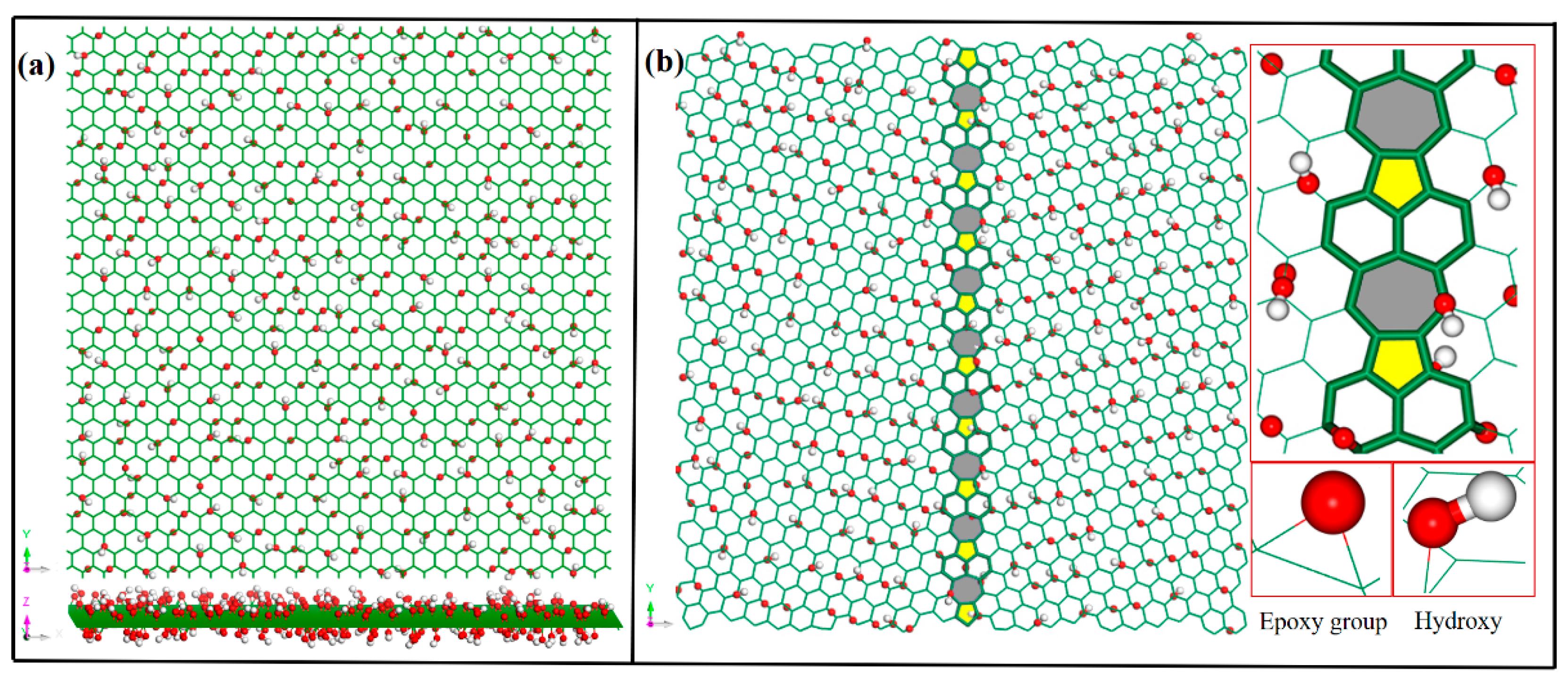
We rotate two sheets of the same graphene at a certain angle along the y-axis, and then connect the edges with five-membered, six-membered, and seven-membered rings. Gbs are formed by periodic arrangement of carbon rings formed by non-six-membered rings. If two sheets of graphene rotate in opposite directions and at the same angle, the structure formed is symmetrical polycrystalline graphene. According to the Lerf–Klinowski model [22], hydroxyl and epoxy-group functional groups were introduced on the basis of the polycrystalline graphene model to obtain the PGO. They were randomly and uniformly distributed on both sides of PGO. GBs of models can be described by the misorientation angle: θ = θL + θR (where θL and θR are the rotation angles of the left and right parts respectively). When θL = θR, symmetrical GBs are formed. The oxygen-containing functional groups densities of PGO models can be defined as R [23], where, NC is the total number of carbon atoms, and is the number of carbon atoms connected with functional groups. The parameter R of the model can be changed by adding or subtracting the number of hydroxyl and epoxy groups to meet our needs.
According to the above, the simulation cell sizes of GO and PGO models are chosen to be around 61.49 Å in length and 63.90 Å in width, and they are sufficiently larger than GBs. Their misorientation angle θ equals 30° or 21.8°, and functional group densities R equals 5.1%, 10%, 20%, 30% and 50%. We placed the same amount of hydroxyl and epoxy groups in them. The established GO model and PGO model are shown in Figure 1a,b, respectively.
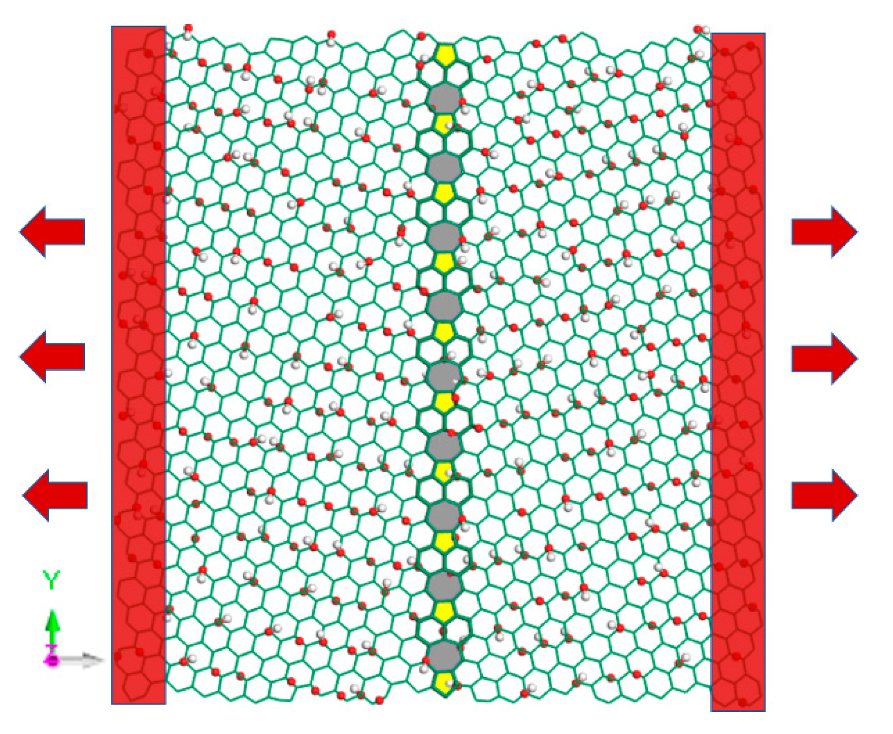
Before tensile simulation, fully relax the structure to obtain the most stable configuration. Periodic boundary conditions are used in the three directions of the models. To reduce the simulation error, the time step is taken as 0.25 fs. In the NPT ensemble (constant number of atoms, N; constant pressure, P; and constant temperature, T), conjugate gradient algorithm is first used to minimize the local energy of the initial models, and then relax 100,000 steps with Nose–Hoover thermostat for temperature control at 300 K. After the relaxation is completed, the atomic configuration of PGO shows irregular folds like GO, as shown in Figure 2. Uniaxial tension along the x-axis, i.e., perpendicular to the GBs, is applied to each model while the pressure of other two directions is kept constant at zero. During the tensile process, the simulation results obtained by setting the pressure in this way could reflect the Poisson’s ratio more realistically. In addition, the tensile strain rate is set to 0.00001 fs−1, and the whole process is guaranteed to be carried out in the NPT ensemble. Figure 3 shows the tensile diagram of PGO.
3. Results and Discussion
3.1. Validation of Model
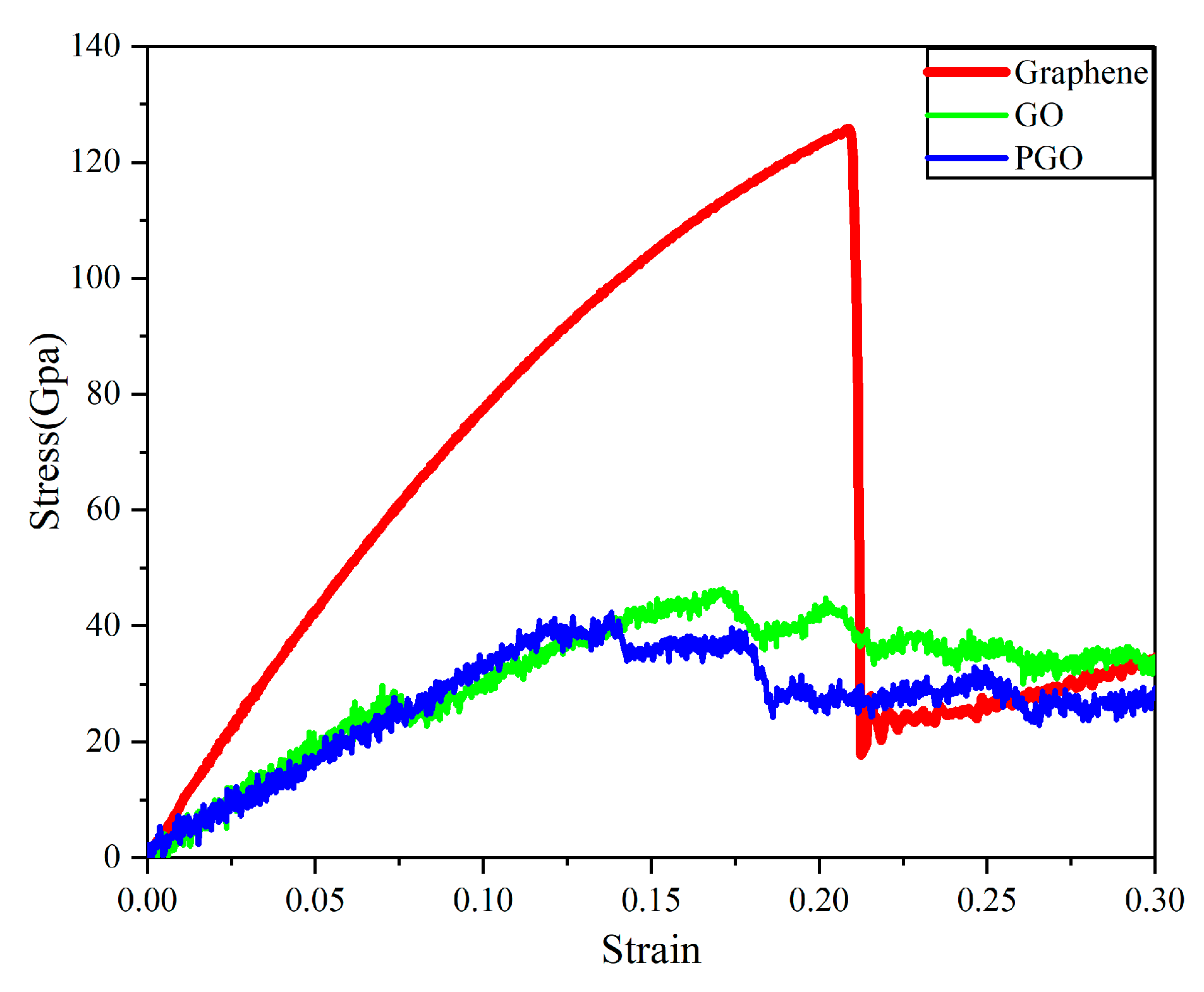
In order to verify the correctness of the simulation method and model, uniaxial tensile tests of graphene and GO under the same conditions were also carried out in this work. Airebo force field was used for graphene and Reaxff force field was used for GO. Adopting the method described in the previous section, can we get the stress-strain curves of the three models (plot in Figure 4). The ultimate stress of graphene obtained is about 126 Gpa (zigzag orientation) and is consistent with the results recorded by most scholars [24,25,26,27,28]. Due to the fracture and regeneration of chemical bonds during the tensile process, GO and PGO can continue to bear the tensile load for a while after some bonds are broken, which is completely different from graphene. For GO, it has the ultimate stress of about 46 Gpa (zigzag orientation), and the conclusion is close to 39.2 GPa obtained by Cao et al. [14] with DFT calculations. Since the functional groups densities and the ratio of functional groups will affect the mechanical properties of GO, the calculation results acquired under different simulation conditions will be slightly diverse. The ultimate stress of PGO in Figure 4 is about 41 GPa (R = 30%, θ = 21.8°), which is about 10.9% lower than that of GO, and the corresponding ultimate strain is 0.14. Obviously, the addition of GBs to PGO will cause the mechanical characteristics of the model to be reduced due to the failure to form perfect six-member rings at the GBs [29]. On the other hand, we can see stress fluctuations after the ultimate stress was achieved of GO and PGO. Because of the phenomenon of adsorption, different atoms will re-form bonds (carbon–carbon bonds and carbon–oxygen bonds) after the fracture. The regenerated bonds can still temporarily maintain a certain tensile strength, and they will lead to a slight increase in stress. In these processes, there is both bond breakage and bond regeneration, and the time of bond breakage is different, which leads to irregular stress fluctuations. The Reaxff force field can reflect the changes of these chemical bonds, so the obtained stress–strain curve will have irregular oscillations after reaching the ultimate stress.
To illustrate the effect of the randomness of the functional group distribution on the mechanical properties, two other PGO models with different functional group distributions (both randomly distributed) were created with the same R and θ. We obtained the data that almost coincides with the stress–strain curves of PGO in Figure 4. Therefore, it is considered that the influence of the random distribution of functional groups can be ignored.
3.2. Influence of Grain Boundaries (GBs)
In polycrystalline graphene, the strength of the five-seven rings at the GBs is not as high as that of the six-membered rings, and the orientation of carbon–carbon bonds inside the structure is various, resulting in different stress conditions under tension. Instability and fracture occur more easily at GBs. Therefore, the tensile fracture of polycrystalline graphene generally propagates along the GBs, bringing about overall failure during subsequent stages [30]. We noted that the six-member rings are no longer continuous in PGO because of GBs, thus changing the atomic arrangement, causing its internal structure to be more unstable than before, and further changing the tensile fracture behavior.
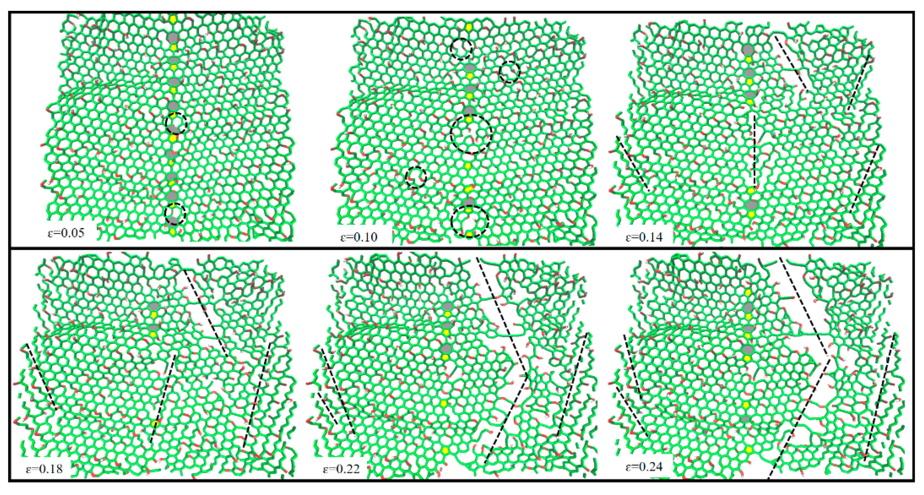
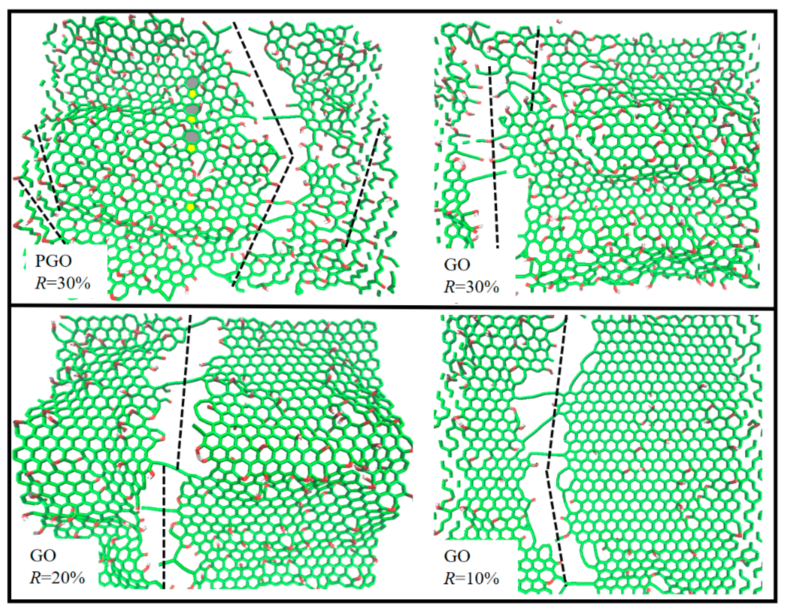
Figure 5 shows the dynamic rupture process of the preceding PGO with R = 30%, θ = 21.8°, following crack initiation. When the strain equal to 0.05, the carbon-carbon bonds in the model were elongated, and bond fracture has begun to grow at the GBs. When continuing to stretch to the strain of 0.1, the bond fracture can be observed not only at the GBs, but also in the six-membered rings on the left and right sides. Meanwhile, the right-hand six-membered rings tend to break diagonally. Up to the strain of 0.14, PGO shows bond failure in many regions, mainly in the zigzag direction. Shortly thereafter large areas of the model were destroyed until it could no longer support uniaxial tension. As can be seen in Figure 6, the tensile fracture of GO is basically perpendicular to the tensile direction. Also, symmetrical bicrystal graphene has the same type of crack growing. Quite unexpectedly, after introducing the GBs in PGO at R = 30%, cracks are more inclined to produce diagonally and no longer perpendicular to the tensile direction. In this case, the grains on the left and right sides need to be rotated at a certain angle, causing the tensile direction to no longer be along the zigzag direction and specifically changing the forced form of atoms and bonds. That’s why the failure form of PGO does not behave like the traditional tensile failure of graphene or GO, but presents multiple oblique cracks along the zigzag direction. The potential energy at GBs of PGO is significantly higher than that at the non-grain boundaries (non-GBs) during the tensile process. Therefore, in the prophase of stretching, cracks initially grow at the GBs because of the highest energy and most instability in this area. Meanwhile, the strong sp2 bonds cause an out-of-plane geometric effect due to the connection with hydroxyl and carboxyl groups, and relatively weak sp3 bonds were created. The twisted carbon bonds connected to functional groups are easily affected not only by the in-plane tension, but also by the out-of-plane weak van der Waals force, giving rise to uneven stress distribution in this region, and then rupture. Based on this, point defects were generated in the area where the functional groups were connected at the non-GBs. Then the cracks will propagate along the zigzag direction from point defects to failure finally.
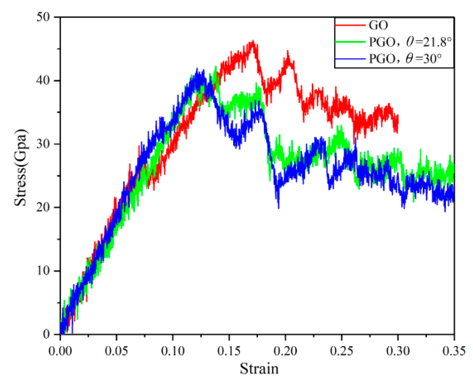
Another two PGO models at R = 30% with symmetric GBs were established, their misorientation angles were 21.8° and 30°, respectively, whose uniaxial tensile stress–strain curves were shown in Figure 7. GO without GBs has the ultimate stress of 46 Gpa, and the corresponding strain is 0.17. After the introduction of GBs, its mechanical properties decrease. When θ equals 21.8°, the ultimate stress and ultimate strain of PGO is 41 Gpa and 0.14, respectively. We can calculate that the ultimate stress of PGO decreases by 12.2%, compared with GO at the same oxygen content. The carbon atoms at the junction of the grain boundaries were at a state of lattice mismatch because of the presence of GBs. Compared with carbon atoms of the six-membered rings, they are more unstable and have a higher “escape force” at the GBs, thus further reducing the mechanical properties of PGO. It is noteworthy that the stress–strain curves of PGO at different misorientation angles almost overlap before reaching the ultimate stress, following by the appearance of a slight difference after being broken. This observation implies that the misorientation angle θ has almost no effect on the uniaxial tensile properties of PGO at R = 30%.
3.3. Influence of Functional Groups
3.3.1. Oxygen-Containing Functional Groups Densities
For GO, the oxygen content directly affects its mechanical properties. Yang et al. [7] found that the ultimate stress of GO could reach 97 Gpa at R = 3.39%, close to the strength of pure graphene, but it drops to 36 Gpa when R reaches 81.38%. It’s not surprising that the oxygen content R-value of PGO also affects its mechanical properties to a certain extent. As shown in Figure 8, the ultimate stress of PGO gradually decreases with the increase of R at θ = 21.8°. Only a small part of the carbon atoms are connected with functional groups at R = 5.10%, and they are all far apart from each other with no interaction between them. The calculated ultimate stress is 52 GPa, which is 58.7% lower than that of pure graphene. When R increases to 50%, most of the carbon atoms are connected with functional groups. Some of them have strong interactions, which makes the area where the functional groups gather unstable, leading to bond breakage and re-bonding. After forming more porous defects, the ultimate stress drops to 32 Gpa, which is 74.6% lower than that of pure graphene. In terms of the ultimate strain, it shows a downward trend with the increase of R (R < 50%), which is the same as the change of ultimate stress, but the ultimate strain increases at R = 50% instead. According to our analysis, when the oxygen content of the functional group reaches a high value, hydrogen bonds will form between the close epoxy groups and hydroxyl groups, which will strengthen the structural system and increase the ultimate strain. As a result, the oxygen content R plays a vital role in the fracture process of PGO, but the deformation behavior will be different due to the discrepancy on the density of oxygen-containing functional groups.
3.3.2. Composition of Functional Groups
As we mentioned earlier, we conclude that GBs and R influence the mechanical properties of PGO. In this section, we will discuss how the composition of functional groups affects mechanical properties [31]. To this end, uniaxial tensile simulations were carried out for models containing different functional groups. PGO-1(containing only epoxy groups) and PGO-2 (containing only hydroxyl groups) were compared with PGO-3 (the number of epoxy groups and hydroxyl groups is 1:1). The specific parameters of the models are listed in Table 1.
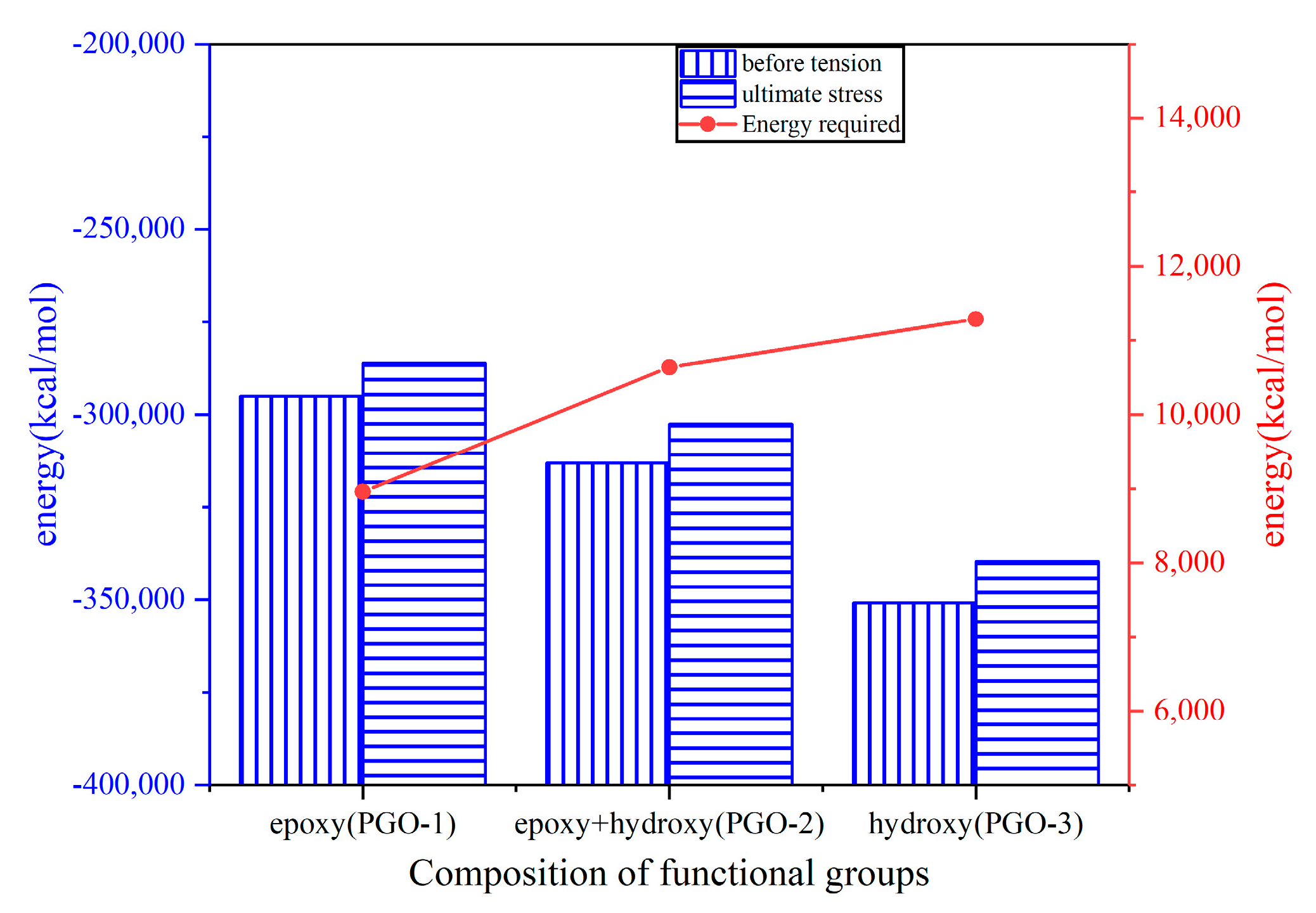
The ultimate stress of PGO-3 is 44 Gpa, which is 15.8% higher than that of PGO-1 (38 Gpa), while that of PGO-2 is between the results of PGO-1 and PGO-3. We can conclude that the carbon rings connected with hydroxyl groups can withstand greater tensile stress than those connected with epoxy groups. The energy diagram of Figure 9 shows that after relaxation, the energy ((vertical column) of PGO-1 and PGO-3 before tension is the highest and the lowest, respectively. In other words, PGO-1 is the most unstable and prone to fracture among the three models. The red broken line is the energy required for the models to be stretched to the ultimate stress. The energy required for PGO-1, PGO-2 and PGO-3 are 8959.19 kcal/mol, 10,637.01 kcal/mol and 11,287.61 kcal/mol, respectively. Obviously, PGO-1 is more likely to reach fracture energy during tensile loading, resulting in structural failure. This also explains the higher ultimate strength of epoxy-containing PGO than hydroxy-containing PGO. Nevertheless, the ultimate strain of PGO-1 containing epoxy groups is larger than that of PGO-3 containing hydroxyl groups, which is just opposite to the ultimate stress. Interestingly, we can find that the carbon–carbon bonds connecting with epoxy groups of PGO-1 break, forming closed carbon–oxygen rings together with the epoxy groups, and continue to bear the tension during uniaxial tension (Figure 10). With the increase of tensile strain, the closed carbon–oxygen rings are gradually opened until they are completely destroyed. In turn, PGO-3 cannot form carbon–oxygen rings with the carbon atoms like PGO-1. Even so, it is also the carbon–carbon bonds connecting functional groups that break first. On this basis, the cracks continue to expand and eventually lead to complete failure. When the strain is 0.12, large cracks have appeared in PGO-3, but the carbon–oxygen rings formed in PGO-1 can continue to undergo the tensile strain, and no obvious cracks appear. Since the carbon–oxygen rings formed after the carbon-carbon bonds break in the tensile fracture process of PGO-1 can still withstand the tensile strain, it has a higher ultimate strain than PGO-3.
3.3.3. Distribution of Functional Groups
Despite the positions of functional groups being random in the synthesis of PGO, it is essential to reveal the effect of its distribution. We proceeded to study the effect of the distribution positions of functional groups in PGO directionally, and uniaxial tensile simulations were performed for another two models: PGO-4 (functional groups are only at GBs) and PGO-5 (functional groups are only at non-GBs).
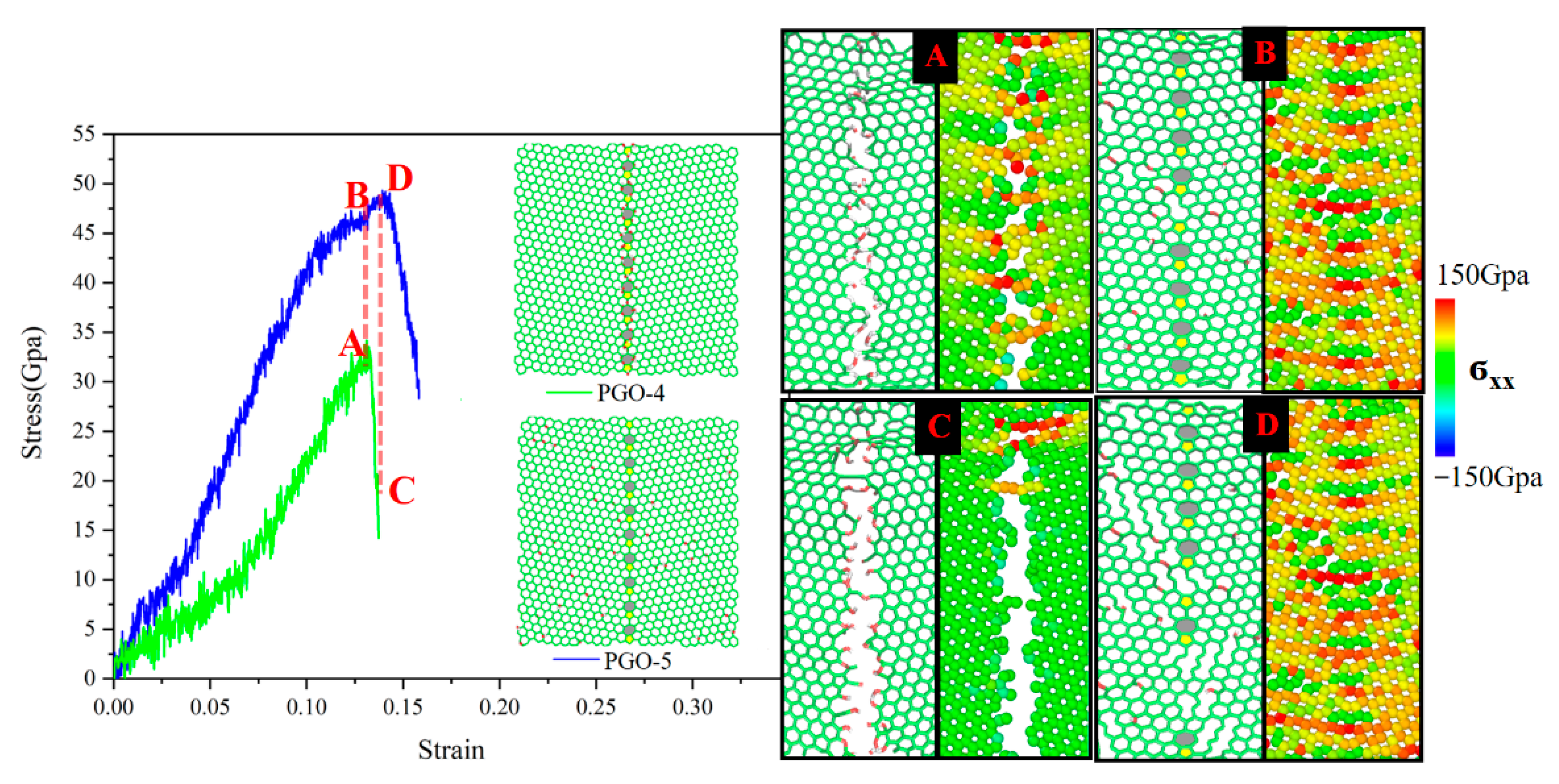
The results of PGO-4 and PGO-5 (R = 5.3%, θ = 21.8°) are depicted in Figure 10, the ultimate stresses are 34 Gpa and 49 Gpa, respectively. According to this figure, the mechanical properties of PGO will decrease to the minimum if functional groups are distributed precisely at GBs. Its ultimate stress drops about 30.6% compared with the PGO with functional groups locating at non-GBs. Moreover, the cracks initiate at the GBs and fracture occurs along the GBs subsequently. If the functional groups are distributed at non-GBs, cracks also initiate at GBs first, but the difference is that point defects will appear in many places later. The cracks grow from the point defects and spread along the zigzag direction until failure. During the tension of PGO-4, the carbon–carbon bonds of five-seven rings connected with functional groups begin to break first. We all can see from the atomic stress distribution of point A in Figure 11 that the atoms at GBs have the highest atomic stress relative to other places. The carbon–carbon bonds are most likely to break here. Later the crack develops gradually along the GBs. The analysis suggests that the stress concentration caused by the GBs as a kind of defect, combined with the formation of relatively weak sp3 hybrid carbon due to the addition of functional groups, forms a defect coupling amplification mechanism, which further reduces the uniaxial tensile strength of PGO (functional groups distribute at GBs). Through a comparison, we noticed that PGO-5 can still bear the tensile load although PGO-4 has reached the ultimate stress. As revealed in Figure 11 at point B, the stress of carbon atoms in the five-seven rings at GBs is relatively high, so are the carbon atoms at non-GBs connected with functional groups. Therefore, the fracture of carbon–carbon bonds can be observed at both GBs and non-GBs. From the bond fracture diagram and atomic stress diagram of points A and B, it can be found that PGO-5 can bear greater tensile load than PGO-4, which means that PGO-5 has higher ultimate stress than PGO-4. When PGO-5 reaches the ultimate stress (point D in FIG. 10), cracks can be observed at both non-GBs and GBs. Thus, PGO-5 can no longer bear the tensile load. At this moment, PGO-4 has been completely destroyed (point C in Figure 11). Specifically, most of the atomic stress is close to zero.
4. Conclusions
A comparative study utilizing MD simulations was carried out to uncover the uniaxial tensile law of PGO. Through internal field coupling (oxygen-containing functional groups, GBs assumed to be special defects), graphene was given a “bottom-up” multi-element structure-space design performance, and then the influence of defect coupling on its mechanical properties was studied. Research shows that:
The presence of GBs increased the initial strain of GO (near the GBs), causing the strong six-membered rings of GO to produce a “degradation” effect. The stress concentration of PGO was more obvious than that of graphene and GO because of the coupling effect of the outer field (tensile stress) and the inner field (GBs). The atoms at GBs were more likely to reach the critical threshold, resulting in the formation of defect clusters. From the energy point of view, atoms at GBs were exposed to the “escape force” (increase of the initial strain), and atomic thermal vibration of average energy increases. When the energy of atoms was large enough to overcome the bondage of the surrounding atoms, the atoms left the equilibrium position leading to the formation of defects, which meant the performance of mechanical properties decreased from the macro point of view. Furthermore, the GBs exhibited an “induction” role in the fracture process of PGO. The initial crack “germinated” at GBs followed by the induction of cracks in several regions. Once initiated, cracks propagated along the zigzag direction.
In terms of PGO, in-plane sp2 carbon atoms were transformed into out-of-plane sp3 hybrid carbon atoms due to the existence of functional groups, which weakened the inter-atomic bonding energy and triggered the “degeneration” of mechanical properties. The ultimate stress of PGO showed a tendency to decrease with the increase of oxygen content of functional groups, and the “degradation” to mechanical properties of PGO by epoxy groups was slightly greater than that of hydroxyl groups with the same oxygen content. The epoxy groups could reconstitute the closed rings with the broken carbon rings to withstand the higher tensile strain. Correspondingly, if more functional groups were distributed at GBs, the weakening of functional groups and GBs on mechanical properties would be further superimposed. From a macro perspective, the mechanical properties were minimized. This observation implies that functional groups should be avoided at GBs as far as possible.
Author Contributions
X.X. carried out the work of literature research and study design in the early stage. Z.Z. was responsible for the figure, data collection, and data analysis. W.Y. was mainly responsible for the final data summary and analysis as well as the writing of the article. All authors have read and agreed to the published version of the manuscript.
Funding
This research was funded by the Key projects of the National Natural Science Foundation of China, grant number 11932010.
Institutional Review Board Statement
Not applicable.
Informed Consent Statement
Informed consent was obtained from all subjects involved in the study.
Data Availability Statement
The data of this study are available from the corresponding author upon reasonable request.
Conflicts of Interest
No potential conflict of interest was reported by the authors.
References
- Wang, Y.; Liu, Z.S. Spontaneous rolling-up and assembly of graphene designed by using defects. Nanoscale 2018, 10, 6487–6495. [Google Scholar] [CrossRef] [PubMed]
- He, L.C.; Guo, S.S.; Lei, J.C.; Sha, Z.; Liu, Z. The effect of Stone-Thrower-Wales defects on mechanical properties of graphene sheets—A molecular dynamics study. Carbon 2014, 75, 124–132. [Google Scholar] [CrossRef]
- Wang, Y.; Lei, J.C.; Liu, Z.S. Molecular dynamics study on the anisotropic Poisson’s ratio of the graphene. Diam. Relat. Mater. 2019, 93, 66–74. [Google Scholar] [CrossRef]
- Georgakilas, V.; Tiwari, J.N.; Kemp, K.C.; Perman, J.A.; Bourlinos, A.B.; Kim, K.S.; Zboril, R. Noncovalent functionalization of graphene and graphene oxide for energy materials, biosensing, catalytic, and biomedical applications. Chem. Rev. 2016, 116, 5464–5519. [Google Scholar] [CrossRef] [Green Version]
- Zheng, Q.B.; Geng, Y.; Wang, S.J.; Li, Z.; Kim, J.-K. Effects of functional group on the mechanical and wrinkling properties of graphene sheets. Carbon 2010, 48, 4315–4322. [Google Scholar] [CrossRef]
- Cao, R.; Chen, Z.; Wu, Y.H.; Tu, Y.; Wu, G.; Yang, X. Precisely controlled growth of poly(ethyl acrylate) chains on graphene oxide and the formation of layered structure with improved mechanical properties. Compos. Part A 2017, 93, 100–106. [Google Scholar] [CrossRef]
- Yang, Z.; Sun, Y.J. Tension dynamics of graphene oxide and peculiar change of yield strain. Appl. Nanoence 2020, 10, 1825–1831. [Google Scholar] [CrossRef]
- Nardelli, M.B.; Fattebert, J.L.; Orlikowski, D.; Roland, C.; Zhao, Q.; Bernholc, J. Mechanical properties, defects and electronic behavior of carbon nanotubes. Carbon 2000, 38, 1703–1711. [Google Scholar] [CrossRef]
- Han, J.; Ryu, S.; Sohn, D.; Im, S. Mechanical strength characteristics of asymmetric tilt grain boundaries in graphene. Carbon 2014, 68, 250–257. [Google Scholar] [CrossRef]
- Grantab, R.; Shenoy, V.B.; Ruoff, R.S. Anomalous strength characteristics of tilt grain boundaries in graphene. Science 2010, 330, 946–948. [Google Scholar] [CrossRef] [Green Version]
- Song, Z.; Artyukhov, V.I.; Yakobson, B.I.; Xu, Z. Pseudo hall-petch strength reduction in polycrystalline graphene. Nano Lett. 2013, 13, 1829–1833. [Google Scholar] [CrossRef] [PubMed]
- Lee, G.-H.; Cooper, R.C.; An, S.J.; Lee, S.; van der Zande, A.; Petrone, N.; Hammerberg, A.G.; Lee, C.; Crawford, B.; Oliver, W.; et al. High-strength chemical-vapor deposited graphene and grain boundaries. Science 2013, 340, 1073–1076. [Google Scholar] [CrossRef]
- Rasool, H.I.; Ophus, C.; Klug, W.S.; Zettl, A.; Gimzewski, J.K. Measurement of the intrinsic strength of crystalline and polycrystalline graphene. Nature Commun. 2013, 4, 2811. [Google Scholar] [CrossRef]
- Cao, C.H.; Daly, M.; Singh, C.V.; Sun, Y.; Filleter, T. High strength measurement of monolayer graphene oxide. Carbon 2015, 81, 497–504. [Google Scholar] [CrossRef]
- Yang, Z.; Sun, Y.J.; Ma, F. Interlayer spacing of multilayer graphene oxide: Influences of oxygen-containing group density, thickness, temperature and strain. Appl. Surf. Sci. 2020, 529, 147075. [Google Scholar] [CrossRef]
- Hou, D.S.; Yang, T.J. A reactive molecular dynamics study of graphene oxide sheets in different saturated states: Structure, reactivity and mechanical properties. Phys. Chem. Chem. Phys. 2018, 20, 11053–11066. [Google Scholar] [CrossRef]
- Van Duin AC, T.; Dasgupta, S.; Lorant, F.; Goddard, W. ReaxFF: A reactive force field for hydrocarbons. J. Phys. Chem. A 2001, 105, 9396–9409. [Google Scholar] [CrossRef] [Green Version]
- Chenoweth, K.; Van Duin, A.C.; Goddard, W.A. ReaxFF reactive force field formolecular dynamics simulations of hydrocarbon oxidation. J. Phys. Chem. A 2008, 112, 1040–1053. [Google Scholar] [CrossRef] [Green Version]
- Medhekar, N.V.; Ramasubramaniam, A.; Ruoff, R.S.; Shenoy, V.B. Hydrogen bond networks in graphene oxide composite paper: Structure and mechanical properties. ACS Nano 2010, 4, 2300–2306. [Google Scholar] [CrossRef]
- Devanathan, R.; Chase-Woods, D.; Shin, Y.; Gotthold, D.W. Molecular dynamics simulations reveal that water diffusion between graphene oxide layers is slow. Sci. Rep. 2016, 6, 29484. [Google Scholar] [CrossRef]
- Bagri, A.; Grantab, R.; Medhekar, N.; Shenoy, V. Stability and formation mechanisms of carbonyl-and hydroxyldecorated holes in graphene oxide. J. Phys. Chem. C 2010, 114, 12053–12061. [Google Scholar] [CrossRef]
- Lerf, A.; He, H.; Forster, M.; Klinowski, J. Structure of graphite oxide revisited. J. Phys. Chem. B 1998, 102, 4477–4482. [Google Scholar] [CrossRef]
- Yang, Z.; Sun, Y.J.; Ma, F.; Lu, Y.; Zhao, T. Pyrolysis mechanisms of graphene oxide revealed by ReaxFF molecular dynamics simulation. Appl. Surf. Sci. 2020, 509, 145247. [Google Scholar] [CrossRef]
- Yao, W.J.; Fan, L. The effect of ion irradiation induced defects on mechanical properties of graphene/copper layered nanocomposites. Metals 2019, 9, 733. [Google Scholar] [CrossRef] [Green Version]
- Pei, Q.X.; Zhang, Y.W.; Shenoy, V.B. A molecular dynamics study of the mechanical properties of hydrogen functionalized graphene. Carbon 2010, 48, 898–904. [Google Scholar] [CrossRef]
- Sadeghzadeh, S.; Rezapour, N. The mechanical design of graphene nanodiodes and nanotransistors: Geometry, temperature and strain effects. RSC Adv. 2016, 6, 86324–86333. [Google Scholar] [CrossRef]
- Yao, W.J.; Fan, L. Research on the correlation of mechanical properties of BN–graphene–BN/BN vertically-stacked nanostructures in the presence of interlayer sp3 bonds and nanopores with temperature. Phys. Chem. Chem. Phys. 2020, 22, 5920–5928. [Google Scholar] [CrossRef]
- Zhao, S.J.; Xue, J.M. Mechanical properties of hybrid graphene and hexagonal boron nitride sheets as revealed by molecular dynamic simulations. J. Phys. D 2013, 46, 135303. [Google Scholar] [CrossRef]
- Yi, L.J.; Yin, Z.N.; Zhang, Y.Y.; Chang, T. A theoretical evaluation of the temperature and strain-rate dependent fracture strength of tilt grain boundaries in graphene. Carbon 2013, 51, 373–380. [Google Scholar] [CrossRef]
- Liu, T.H.; Pao, C.W.; Chang, C.C. Effects of dislocation densities and distributions on graphene grain boundary failure strengths from atomistic simulations. Carbon 2012, 50, 3465–3472. [Google Scholar] [CrossRef]
- Tavakol, M.; Montazeri, A.; Aboutalebi, S.H.; Azgari, R. Mechanical properties of graphene oxide: The impact of functional groups. Appl. Surf. Sci. 2020, 525, 146554. [Google Scholar] [CrossRef]
Figure 1.
(a) Graphene oxide (GO) model; (b) polycrystalline graphene oxide (PGO) model (carbon atoms and carbon–carbon bonds are shown in green, oxygen atoms in red, and hydrogen atoms in white).
Figure 1.
(a) Graphene oxide (GO) model; (b) polycrystalline graphene oxide (PGO) model (carbon atoms and carbon–carbon bonds are shown in green, oxygen atoms in red, and hydrogen atoms in white).

Figure 2.
Model of polycrystalline graphene oxide after relaxation.

Figure 3.
Tensile diagram of polycrystalline graphene oxide.

Figure 4.
The stress–strain curves under uniaxial tension.

Figure 5.
Tensile failure process of polycrystalline graphene oxide.

Figure 6.
Tensile failure process of polycrystalline graphene oxide and graphene oxide at different R.
Figure 6.
Tensile failure process of polycrystalline graphene oxide and graphene oxide at different R.

Figure 7.
Uniaxial tensile stress-strain curves at R = 30%.

Figure 8.
Ultimate stress and ultimate strain values of PGO under different oxygen content (θ = 21.8°).
Figure 8.
Ultimate stress and ultimate strain values of PGO under different oxygen content (θ = 21.8°).

Figure 9.
Energy change of PGO during the tensile process.

Figure 10.
Fracture and reconstruction of the bonds between PGO-1 and PGO-3.

Figure 11.
Uniaxial tensile stress-strain diagram and model diagram of pgo-4 and pgo-5 (left frame), bond fracture diagram and atomic stress distribution diagram of corresponding marked points (right frame). Points A and B: The moment when PGO-4 reaches the ultimate stress; Points C and D: The moment when PGO-5 reaches the ultimate stress.


Table 1.
Composition of functional groups and uniaxial tensile mechanical properties of PGO model.
| Total Number of Carbon Atoms | Functional Groups Densities R | Number of Epoxy Groups | Number of Hydroxyl Groups | Ultimate Stress (Gpa) | Ultimate Strain | |
|---|---|---|---|---|---|---|
| PGO-1 | 1481 | 30% | 222 | 0 | 38 | 0.14 |
| PGO-2 | 1481 | 30% | 148 | 148 | 41 | 0.14 |
| PGO-3 | 1481 | 30% | 0 | 444 | 44 | 0.12 |
Publisher’s Note: MDPI stays neutral with regard to jurisdictional claims in published maps and institutional affiliations. |
© 2021 by the authors. Licensee MDPI, Basel, Switzerland. This article is an open access article distributed under the terms and conditions of the Creative Commons Attribution (CC BY) license (http://creativecommons.org/licenses/by/4.0/).
Share and Cite
MDPI and ACS Style
Xu, X.; Zhang, Z.; Yao, W. Mechanical Properties of Graphene Oxide Coupled by Multi-Physical Field: Grain Boundaries and Functional Groups. Crystals 2021, 11, 62. https://0-doi-org.brum.beds.ac.uk/10.3390/cryst11010062
AMA Style
Xu X, Zhang Z, Yao W. Mechanical Properties of Graphene Oxide Coupled by Multi-Physical Field: Grain Boundaries and Functional Groups. Crystals. 2021; 11(1):62. https://0-doi-org.brum.beds.ac.uk/10.3390/cryst11010062
Chicago/Turabian StyleXu, Xu, Zeping Zhang, and Wenjuan Yao. 2021. "Mechanical Properties of Graphene Oxide Coupled by Multi-Physical Field: Grain Boundaries and Functional Groups" Crystals 11, no. 1: 62. https://0-doi-org.brum.beds.ac.uk/10.3390/cryst11010062
Note that from the first issue of 2016, this journal uses article numbers instead of page numbers. See further details here.