Article

Textures of Nematic Liquid Crystal Cylindric-Section Droplets Confined by Chemically Patterned Surfaces

1
School of Physics and Astronomy, University of Leeds, Leeds LS2 9JT, UK
2
School of Chemistry, University of Leeds, Leeds LS2 9JT, UK
3
Leeds Institute of Medical Research, University of Leeds, Leeds LS2 9JT, UK
*
Author to whom correspondence should be addressed.
Submission received: 17 December 2020 / Revised: 8 January 2021 / Accepted: 12 January 2021 / Published: 15 January 2021
(This article belongs to the Special Issue Patterned-Liquid-Crystal for Novel Displays)

Abstract

:
The director fields adopted by nematic liquid crystals (LCs) that are confined by the surface to form long, thin droplets are investigated using polarising optical microscopy. Samples are produced by de-wetting of the LC on a surface patterned with alternating high-surface energy and low-surface energy stripes of 10–30 μm width. The droplets obtained are expected to adopt a profile which is that of a longitudinal section of a cylinder and, as this suggests, the director fields observed are variants in the case where the LC is constrained in a cylindrical capillary or fibre. Hence, when there is normal anchoring at the air interface, the textures observed are related to the well-known escaped radial texture (for the nematic LC mixture E7) or plane polar texture (for the LC mixture MLC6609). More surprising is the observation that the nematic LC mixture MLC7023, which is anchored in a planar or tilted manner at the air interface, also gives what appears to be an escaped radial director field. As an exploration of the possibility of using these systems in creating sensors, the effects of adding a chiral dopant and of adding water to the substrates are also investigated.

1. Introduction

Understanding how the director fields of liquid crystals (LCs) respond to confinement in thin films, fibres, droplets, etc., is fundamental to our use of these materials in displays [1,2,3], in optical compensating films [4], in the production of high-tensile strength fibres [5,6,7] and in chemical and biological sensors [8,9,10]. In the case of sensor applications, work has predominantly focused on thermotropic nematic LCs confined in thin “open” films [11,12,13,14,15,16] or in spherical droplets: either “free” droplets [17,18,19,20] or “capped” droplets attached to a surface [21,22,23,24]. In most cases, detection relies on the amplification that is seen when a small change at the surface alters the sign of the surface anchoring, causing a change in the director field within the bulk, which, in turn, leads to a detectable optical response [25]. The preferred scale of confinement for such systems is for films of the order of 10–30 μm thick or for droplets of the order of 10–30 μm in diameter. As part of a project aimed at developing novel LC-based sensor and biosensor systems, this paper explores a different form of confinement: containment in long, thin droplets. When a planar surface is patterned with alternating hydrophilic and hydrophobic stripes that are 10–30 μm wide, liquids added to the surface de-wet onto the hydrophilic (high-surface energy) areas, giving an array of long, thin droplets. At this scale, the behaviour of droplets is dictated by the surface tension, giving droplet profiles that are longitudinal sections of a cylinder (Figure 1). These are hemi-cylindrical in the case when the contact angle is 90° (Figure 1b) [26].
Due to the importance of understanding director fields in LC-derived high-tensile strength fibres such as carbon fibre [5,6], Kevlar [7] and spider silk [27,28], cases where the director field of a LC is subject to cylindrical confinement have been investigated in detail both from a theoretical and from an experimental standpoint. As in any confined environment, the system has to adopt a director field that is a compromise between the competing demands of director anchoring, surface curvature and the need to minimise the excess elastic energy within the system [29]. Cross-sections of director fields commonly seen in cylindrical confinement (fibres) [30,31] are shown schematically in Figure 2 and Figure 3. When there is perpendicular anchoring at the surface, the simplest director field imaginable is the “planar radial” field (Figure 2a). This has a defect line strength s = +1 running along its centre. However, except for the very narrowest of capillaries [32], this proves to be unstable relative to the “escaped radial” director field (Figure 2c and Figure 3) [27,33,34,35,36,37,38,39,40,41] or to a situation in which the +1 defect line splits into a pair of +1/2 defect lines, giving the “planar polar” director field (Figure 2b) [5,6,32]. When the anchoring of the nematic at the air to LC surface is planar, the main possible director fields are those in Figure 2d–g. The most commonly seen is the uniform axial arrangement (Figure 2d), which minimises the excess elastic energy within the system.
Compared to the problem of understanding cylindrical confinement, the additional factor seen in the de-wetted droplets, discussed in this paper, is that of anchoring at the LC solid interface. As can be seen from Figure 2 and Figure 3, if the droplets are hemi-cylindrical or close to hemi-cylindrical in shape, some of these director fields can be further stabilised by planar anchoring (Figure 2a–d) and some by perpendicular anchoring (Figure 2e,f) at the solid interface. However, this is only strictly true if the profile of the droplets is hemi-cylindrical. For the nematic LCs discussed in this paper, we found that the droplets were more flattened so that the contact angles were much less than 90° (experimentally determined values of the contact angles are given later in the paper in Table 2 and an experimentally determined droplet profile is shown in Figure 6b). In such cases, either a hybrid aligned director field must result or there must be variation from the “ideal” alignment of the director at the surface.

2. Materials and Methods

2.1. Materials

Acetone (99.5%), Methanol (99.5%) and IPA (99.5%) were purchased from Sigma Aldrich, Merck Group, UK. The mixture E7 was purchased from Synthon Chemicals GmbH & Co. KG, Germany. The mixtures MLC6609, MLC2081 and MLC7023 were provided by Merck Group, UK. Premium glass microscope slides, 1H, 1H, 2H, 2H-perfluorodecyltrichlorosilane (96%) and Decon 90 were purchased from Fisher Scientific (Pittsburgh, PA, USA). Photoresist (S1813) and its developer (MF-319) were purchased from Shipley, UK.

2.2. Microscopy Observation

This was carried out using a DM 2700M polarised light microscope (POM) (Leica Microsystems Ltd, Mannheim, Germany) equipped with a pair of linear polarisers, a Nikon D3000 camera (Nikon, Tokyo, Japan) and a Linkam T95 Peltier hot stage (Linkam Scientific Instruments, Tadworth, UK). A first-order retardation plate (λ wave plate Olympus, Japan) was placed in the optical path of the microscope, with the slow axis of the retarder at +45° to the polariser.

2.3. Alignment of the LCs at the Air Interface and on Glass Slides

In order to check the alignment of LCs at a free air interface, a hole approximately 1.5 mm in diameter was drilled into a glass slide with a Dremel diamond bit. The glass slide was subsequently cleaned by sonication with methanol and dried in an oven at 100 °C for 2 h. In order to deposit the LC within the cavity, 5 µL of LC was pipetted onto the glass slide near to the cavity and a film was created by smearing the LC across the hole by using the flat edge of a razor blade. The alignment observed via polarised optical microscopy and the resultant images are shown in Figure 4.
The alignment of LCs on glass was determined by sonicating glass slides in a Decon 90 and deionised water solution at 60 °C for 1 h before rinsing with water, methanol and IPA before drying in an oven at 100 °C for 2 h. A sandwich cell was formed with a thickness between 8 and 10 μm and the LC was introduced. In each case, the LC was heated into the isotropic phase and slowly cooled into the nematic phase to produce well-aligned samples. The alignment observed via polarised optical microscopy and the resultant images are shown in Figure 5.
For the addition to water, the sample was gently lowered into Milli-Q water.

2.4. Fabrication of the Patterned Substrates

Microscope slides (25 × 75 × 1 mm) were cleaned in an ultrasonic bath using Decon 90, Milli-Q water and isopropanol (10 min for each solution) and blow-dried using a flow of nitrogen. The freshly cleaned slides were baked on a hotplate at 120 °C for 10 min before spin-coating with the positive photoresist S1813 (3000 rpm, 30 s). The slide coated with S1813 (~1.3 µm) was baked at 115 °C for 1 min to remove residual solvent. An MW2 laser direct-write laser system (Durham Magneto Optics Ltd, Durham, UK) was used to expose the S1813 film to create desired paralleled stripes. On each substrate, three widths of high-energy, hydrophilic stripes were created, 10–30 μm. In each case, the low-energy, hydrophobic stripes were 10 μm wide. After exposure, the glass sample was rinsed in MF-319 developer (Shipley) for 45 s to remove the S1813 exposed to UV light. Then, O2 plasma cleaning (5 min, 0.1 mbar, 100 W) was used to fully remove the residual S1813 on the glass surface, after which it was placed in a glass desiccator together with a drop of 1H, 1H, 2H and 2H-perfluorodecyltrichlorosilane. The desiccator was kept overnight at ~0.1 mbar to allow the fluorocarbon self-assembled monolayer (SAM) to form between the S1813 stripes. The slides were cleaned in acetone in an ultrasonic bath for 5 min (3 times) and in IPA (1 min) to fully remove the “non-exposed” S1813. They were cut into small pieces (1 × 1 cm2) for use.

2.5. Addition of the LC

A drop of the LC (2 µL) was placed at one end of the SAM stripes using a plastic pipette tip and spread over the surface of the glass with a doctor blade. This was then heated to a temperature 10 °C above the nematic–isotropic phase transition temperature on a Linkam hot stage. The LC was de-wetted to fill the gap between the SAM stripes. The sample was annealed at this temperature for 5 min and then slowly cooled to room temperature at 2 °C/min. In each case, a series of stripe widths of 10–30 μm was investigated. No significant differences were seen in the observed textures over this scale range. In cases where stripes were incompletely filled, we found that they were still of even width, i.e., breaks occurred along the length of the stripe but the width along the stripe was even and was not less than that expected for full wetting.

2.6. Measurement of the Heights of the Stripes

Reflection-mode images of LC stripes were used to determine the thickness of the droplet stripes. Measurement of the spacing of the interference fringes at the edges of droplets allows the heights to be calculated utilising;
h = m λ 2 n a v ,
where h is the height of the LC stripe, the integer m is the number of fringes observed and λ is the wavelength of reflected light. The average refractive index nav depends on both the director configuration for the droplet and the anisotropic refractive indices for the LC material. From this, the contact angle of the LCs can be calculated by assuming a circular cross-section and using;
2 r h = h 2 + w 2 4 ,
Wherein;
sin θ = w 2 r ,
where w is width of the LC stripe and r is the radius of curvature of the LC. All stripe heights were calculated as an average over a minimum of 10 stripes. The maximum difference between droplets in the same sample was ±1 fringe.

3. Results and Discussion

3.1. Nematic Cylindric-Section Droplets

In a previous paper, we examined the case of long, thin droplets of columnar phases of discotic LCs where the de-wetting occurs when the sample is heated into its isotropic phase [26]. In this work, we report a preliminary investigation of some calamitic nematic LCs. The de-wetted droplets were formed on a solid surface between alternating hydrophilic/hydrophobic stripes. Clean glass was used to provide the high-energy, hydrophilic stripes, whereas the glass was functionalised with a hydrophobic fluorinated self-assembled monolayer to provide the low-energy, hydrophobic surface regions. Hydrophilic stripes of widths in the range 10–30 μm were used and, for each LC, the alignment was shown to be (at least qualitatively) the same over this range. Substrates were heated above the nematic–isotropic transition temperature and then slowly cooled to avoid any influence of flow on the resultant director field. Four room-temperature nematic LCs were chosen which between them show a range of different alignment types: E7 (perpendicular alignment of the director at the air interface and planar or tilted at glass), MLC2081 (perpendicular or slightly tilted alignment of the director at the air interface and planar or tilted at glass), MLC6609 (perpendicular alignment at both glass and air) and MLC7023 (planar or tilted alignment at both glass and air). Other basic properties for these LCs are listed in Table 1. They also show a range of Δn (i.e., polarisability) and Δε (i.e., polarity). There is a simple expectation that when a material has a strongly positive Δε, the longitudinal dipole moment will lead to normal alignment, but that alignment of less polar materials will be affected more by the polarisability anisotropy (high birefringence is often associated with planar or tilted, and low birefringence with normal anchoring). However, as is seen, for this selection of materials, this simple guide only proves valid (at air) for E7 and MLC6609. Anchoring is a complex phenomenon in which both the properties of the LC and those of the surface are critical [20,42].

3.1.1. Alignment of the LCs at Glass and at Air Interfaces

The preferred alignments at the air interface were determined by polarising microscope observations of a thin film suspended across a small hole drilled in a glass slide, and the resultant images are shown in Figure 4. In the cases of E7 and MLC6609, where the alignment of the LC at the air interface is perpendicular (homeotropic), the sample appears black at all angles of rotation when observed using crossed polarisers (except for a little birefringence around the edge due to misalignment on the edge of the glass). In the case of MLC7023, where the alignment is planar or tilted at the air interface, the texture is bright and birefringent. The case of the highly birefringent negative LC MLC2081 is less clear-cut. The film appears to be mostly black but there are also some signs of birefringence. Furthermore, the effect of the alignment on the edge of the hole extends much further into the sample. Probably, this LC has very weak perpendicular anchoring at the air interface, allowing some degree of tilt.
Alignment of LCs at a glass surface was investigated for samples sandwiched between clean glass slides. The resultant images are shown in Figure 5. The LCs E7, MLC7023 and MLC2081 show the Schlieren texture associated with planar or tilted alignment at the interface. MLC6609 shows homeotropic behaviour (except round the edges of the trapped air bubbles) and hence perpendicular alignment.

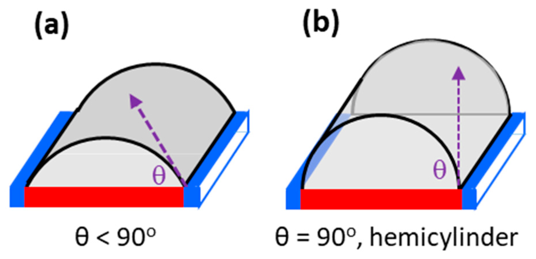
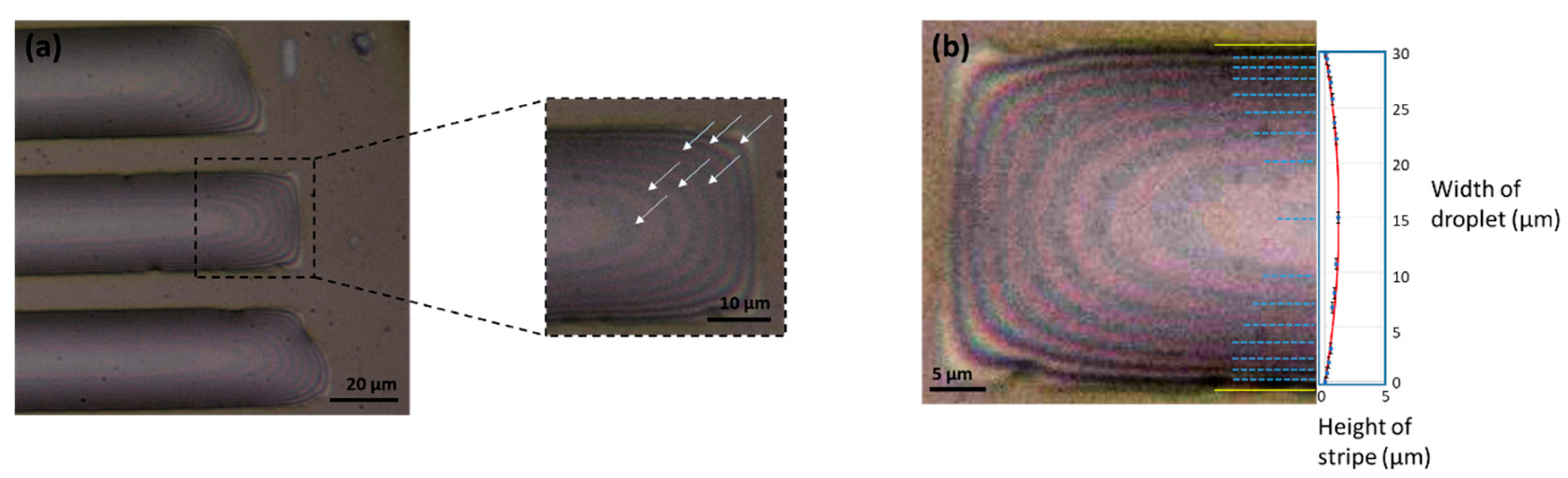
3.1.2. Droplet Profile/Contact Angle Measurements

One consequence of the method used to deposit the LC to the substrate is that there is a small spread in the extent to which each “channel” is filled, under-filled or over-filled, and in each case, a small range of droplet heights and contact angles was obtained. The director fields observed were shown to be independent of this spread in the heights (except, as discussed below, to a small extent in the case of MLC2081). In our previous work on columnar phases of discotic LCs, it was possible to determine the profiles of the droplets using force microscopy [26]. However, nematic LCs are much softer materials and therefore this was not practicable. The alternative method used was to make use of the interference fringes seen when the droplets are observed in reflection mode [43], Figure 6. Counting of these fringes allows the heights to be determined with a reasonable degree of accuracy for three of the LCs, but for MLC2081, the droplets were higher and the fringes at the edges could not be clearly resolved.
If unpolarised light is used to illuminate the droplet with the escaped radial near-hemispherical hybrid aligned nematic (HAN) configuration, the average refractive index is readily shown to be approximately given by;
n a v 1 2 ( n o + n e ) ,
The values obtained are summarised in Table 2. In general, these calamitic nematic LC droplets are significantly flatter; the contact angles are significantly less than those found for the discotic LCs previously examined. Since pinning of a fluid at a hydrophobic SAM/glass interface is a complex phenomenon that is not fully understood, the reason for this difference is not clear [26]. The fact that these are, indeed, close to constant-curvature surfaces was confirmed by plotting the heights obtained for each fringe as a function of its distance from the edge of the droplet (Figure 6b) [43]. As shown, these fit closely to a section of a circle.

3.1.3. Alignment for the De-Wetted Droplets of E7

E7 usually anchors normal at an air interface and planar or tilted on glass (Table 1). When the de-wetted droplets were cooled from the isotropic into the nematic phase, the optical texture observed (Figure 7) is characteristic of an escaped radial director field (Figure 2c and Figure 3). This director field is commonly seen for nematic LCs in cylindrical confinement where there is strong perpendicular anchoring at the curved surface [27,33,34,35,36,37,38,39,40,41] and, in these de-wetted droplets, it would certainly allow the LC to adopt planar alignment at the glass if they were hemi-cylindrical (Figure 3). However, it is perhaps unexpected that the escaped radial director profile is favoured in such flattened droplets. The escaped radial nature of the director field was confirmed using a lambda plate with first-order magenta retardation. When the tint plate is added at 45° between the crossed polarisers as shown in the Figure 7, it translates the birefringence colours observed from first-order grey to first-order yellow or second-order blue depending on whether the slow axis of the wave plate is at 90° to the principle optical axis of the LC or whether they are aligned [44]. As shown in Figure 7b, when it is added and the sample is viewed with the stripes aligned with one of the polarisers, it generates a blocked pattern of alternating blue–yellow and yellow–blue segments [27,34]. This pattern is characteristic of the escaped radial director field, as is the alternating sequence of s = +1 and s = −1 point defects (radial and hyperbolic point defects). The s = +1 (radial) defects in Figure 5b are characterised by the sequence of birefringence colours blue–yellow–blue–yellow (starting in the top right quadrant and proceeding in a circular manner). The s = −1 (hyperbolic) defects are characterised by the sequence of birefringence colours yellow–blue–yellow–blue (when viewed in the same way). Equally characteristic are the patterns observed when the stripes are at 45° to the polarisers. In this case, the images between crossed polarisers alone show the defects connected by a double black line that runs parallel to the stripes (in passing from one side of the stripe to the other, there are two positions in which the director is parallel to one of the polarisers) [34]. When the lambda plate is added, the sequence of birefringence colours across the stripe becomes blue–magenta–yellow–magenta–blue in the case where they are at +45° and yellow–magenta–blue–magenta–yellow where they are at −45°, Figure 5e,f. These results show that, as expected, regardless of the defects, in the centre of the stripe, the director is parallel to the stripe direction and that at the edges of the stripe, it is perpendicular to the stripe direction. That is, the sample is described by the escaped radial configuration shown for both hemi-cylindrical and flattened cylindric-sectional droplets in Figure 8a.

3.1.4. Alignment for the De-Wetted Droplets of MLC2081

Since, in capillaries, escaped radial director fields are usually associated with strong perpendicular anchoring, it was decided to investigate MLC2081. Like E7, this shows planar or tilted anchoring on glass and at the air interface mainly normal, although, as seen in Figure 4, there may be some evidence of tilt; it appears that this anchoring is weaker. The results obtained for this LC are shown in Figure 9. Once again, although there appears to be a little more disorder, the director field is clearly escaped radial in nature. This LC proved the most difficult to fill into the stripe pattern, the droplets were clearly higher and there was also more spread in the droplet heights (more variation in the birefringence stripe-to-stripe). The less birefringent stripes, presumably the lowest contact angle stripes, were the ones that showed the least well-defined escaped radial texture.

3.1.5. Alignment for the De-Wetted Droplets of MLC6609

The nematic LC MLC6609 usually anchors perpendicular both on glass and at the air interface. When the de-wetted droplets are cooled from the isotropic into the nematic phase and observed using crossed polarisers with the polarisers at 0° or 90° to the stripes, they also appear black (a uniform magenta when the lambda plate is added), Figure 10. This is consistent with a segment of the “planar polar” director fields shown in Figure 2b [5,6,32,33]. Since there are no large differences in the elastic constants of E7 or MLC2081 and those of MLC6609 [20], but there is opposite anchoring at the glass/planar interface, it is probable that this is what accounts for the different behaviour of these two LCs. This corresponds to the lower structure of Figure 8b.

3.1.6. Alignment for the De-Wetted droplets of MLC7023

The nematic LC MLC7023 normally anchors in a planar or tilted manner both on glass and at the air interface. It was expected that this LC, like most LCs in capillaries where there is planar anchoring at the walls, would adopt a uniform axial director field with the director lying parallel to the long axis, Figure 2d. However, when a sample comprised of de-wetted droplets of MLC7023 is cooled from the isotropic into the nematic phase, the texture observed is the same as that seen in the case of E7 and that of MLC2081 (compare Figure 11 with Figure 7 and Figure 9). One possible explanation of this surprising observation is that the director is tilted at the air interface so that the director field adopted is like an escaped radial but that it does not become fully normal at this surface (a modified version of that seen in Figure 8a). If the droplets were hemi-cylindrical and the surface curvature were high, an alternative explanation would be that there is the “twisted planar escaped” radial director field shown in the upper portion of Figure 8c. Here, it is assumed that anchoring is planar at both surfaces, that the field is similar to that of an escaped radial close to the glass surface and that the director is constrained by the curvature of the droplets to lie parallel to the direction of the stripes at the air interface. However, this would lead to twisted nematic regions either side of the droplet centre and such regions were not observed. As a result of the contact angle being so low and because the effect of surface curvature on the director alignment is expected to be minimal, a more likely explanation is that the lowest-energy configuration occurs when the director orientation at the air/nematic interface follows the same pattern as that on the glass interface. This alignment is assumed on both interfaces, as shown in the lower schematic of Figure 8c (“planar escaped”). It may also be relevant that MLC7023 is known to be only weakly anchored (at least on a polyimide surface) as compared to E7 [45].

3.2. The Effect of Chirality on Cylindric-Section Droplets

3.2.1. The Effect of Adding a Chiral Dopant on the Alignment of E7.

We also examined the effect of adding a chiral dopant to E7. If there is planar anchoring of the director at an interface, the addition of a chiral dopant to an LC induces a twist in the director field, which propagates perpendicular to the surface. In the case of a nematic LC confined in a capillary, this leads to an ordered director field and simple, characteristic optical textures [46]. However, if the surface anchoring is perpendicular and the pitch length is less than the radius of the capillary, it is not possible to generate an ordered director field and the observed optical textures are focal conic in nature. E7 shows perpendicular alignment at the air interface, and in these de-wetted droplets, it shows an escaped radial director field. As in analogous capillary systems, addition of a chiral dopant with a short pitch disrupts this relatively ordered arrangement. The addition of 8.2 ± 0.1 wt% of the chiral dopant S1011 to E7 should generate a helical pitch of 305 ± 9 nm (the helical twisting power of S1011 is 40 ± 1 μm−1), which is much less than the dimensions of the stripe. When such a sample is slowly cooled from the isotropic into the chiral nematic phase, the chaotic focal conic-type textures shown in Figure 12 are observed.

3.2.2. The Effect of Adding Water to These De-Wetted Droplets

One potential application of these droplets is as an alternative to planar thin films or “free” or “surface-tethered” spherical droplets of LCs in creating biosensors [17,18,47,48,49]. In order for such a sensor to be compatible with biological samples, they need to function in an aqueous environment. However, when water is added to these substrates, the water displaces the LC from the stripes and a large, coalesced, irregularly shaped droplet of the LC is observed. The exception is E7 doped with S1011. Whilst this gives the most disordered director field pattern of all of the systems studied, it is the only system that, when water is added, de-wets in a relatively ordered and controlled manner. When the slide is gently lowered into water, the de-wetting process produces regular lines of surface-tethered droplets, Figure 13. The sizes of the droplets in the example shown in Figure 13 were fairly uniform over the whole sample, 16.9 ± 3.0 μm (PDI 0.023). In the substrate used for this experiment, the “hydrophilic” stripes were 30 μm wide and the “hydrophobic” stripes were 10 μm wide. Careful examination of the images shows that the LC remains attached to the “hydrophilic” stripes. The addition of water will induce planar alignment of the director at the LC/water interface [20,50,51] and for free-floating droplets, this results in a “Frank–Pryce” director field [52,53]—a director field in which there is a single s = +2 defect line and in which the helical axis is radial. One important property of Frank–Pryce droplets, which is exploited, for example, in LC thermometers, is that they reflect visible light at a wavelength related to the chiral pitch of the director field. For chiral droplets, when reflectance optical microscopy is used, what is seen is the so-called “bulls-eye” effect with strong reflection of the light from the centre of each droplet, Figure 13b [18]. In this particular case, the “bulls-eye” is blue/green which is consistent with a helical pitch of 305 nm, which, for an average refractive index of 1.6, gives a predicted selective reflection at 488 nm (blue/green). If these spherical-section droplets have a Frank–Pryce-like structure, then there must be a range of orientations at the planar interface. It is also interesting to note that, whereas the smaller droplets show a clear “bulls-eye”, the reflectance from the larger droplets is more complex.

4. Conclusions

Understanding the director fields adopted by LCs that are confined in these long, thin de-wetted droplets can be approached through a much more extensively researched problem: that of how they behave under cylindrical confinement. However, in these de-wetted droplets, there is the additional factor of the influence of the solid interface, potentially making it a richer problem. For the nematic LCs discussed in this paper, we have related the director fields observed to their preferred anchoring at glass and at air, but the anchoring energies and elastic constant values must also be important. This is illustrated by previous work on the columnar phases of discotic LCs. Hexagonal columnar phases of discotic LCs show two director fields: one with the director (as viewed in projection) along and the other with it across the stripes [26]. The first of these corresponds to a uniform axial director field (a segment of that shown in Figure 2d for a cylinder), which minimises the excess elastic energy but leads to an unfavourable alignment at the LC/solid interface. The second (probably) corresponds to a concentric director field (a segment of the concentric director field shown in Figure 2e) [54], which gives an alignment closer to the preferred alignment at the LC/solid interface but introduces excess “bend” energy into the system. As in any case where LCs are subject to confinement, the director field is a compromise between the demands of surface anchoring and the strain induced by deforming the LC director field. The relative magnitudes of these terms can be important as well as the sign of the anchoring terms. In the case of the hexagonal columnar phase, the tendency to favour perpendicular anchoring at the solid interface (which is weak) is opposed by the (low) energy penalty of introducing bend into the system and the overall outcome depends on the balance between these two factors. Nevertheless, it is shown that, although for nematic LCs confined in capillaries, escaped radial director fields are always associated with perpendicular anchoring at the surface, it appears that, for these flattened droplets, it can occur (or something very similar to escaped radial can occur) regardless of whether the anchoring at the curved surface is perpendicular or tilted/planar.
For the potential use of de-wetted droplets in chemical sensors, it is significant to observe that they are easily fabricated, just requiring adding a nematic LC to a surface pre-patterned with alternating hydrophilic and hydrophobic stripes. However, the director field does not seem to depend on the sign of anchoring at the air interface in quite the way expected; both planar/tilted and perpendicular alignment at this interface can give textures that look very similar. Further, to create a useful biosensor, the air needs to be replaced by water. LC biosensors that have been made so far have been based on “free” droplets (spherical droplets) [17,18,19,20] or on droplets attached to a surface (hemispheres or sections of a sphere) [21,22,23], all of them produced in water. However, when water is added to the arrays of droplets described in this paper, the water, most often, completely displaces the LC from the surface. The interesting exception is the case of the chiral LC, E7 with 8.2% of the chiral dopant S1011, where lines of “tethered” Frank–Pryce-like droplets are produced. Chiral nematic droplets with a Frank–Pryce director field are particularly interesting because they are perhaps the most promising for developing liquid crystal-based biosensors [18,49]. This result may point to an alternative method for producing tethered arrays of LC droplets which is simpler than that which has been used previously [17].
A surprising observation from this work is the strong tendency of systems to form escaped radial director fields even though these droplets have such a shallow profile. This even applies to MLC7023 which anchors in a planar or tilted manner at the air interface (although in this case, the director field could also be “planar escaped”).

Author Contributions

Conceptualisation, R.J.B., J.C.J., S.D.E. and H.F.G.; methodology, P.B., D.A.P., R.J.B., S.D.E. and H.F.G.; validation, P.B., D.A.P., J.C.J., R.J.B., S.D.E. and H.F.G.; formal analysis, P.B., D.A.P. and J.C.J.; resources, S.D.E. and H.F.G.; data curation, P.B., D.A.P., R.J.B., S.D.E. and H.F.G.; writing—original draft presentation, P.B., D.A.P. and R.J.B.; writing—reviewing and editing, P.B., D.A.P., S.A.P., J.C.J., J.A.T.S., R.J.B., S.D.E. and H.F.G.; supervision, R.J.B., S.D.E. and H.F.G.; project administration, R.J.B., S.D.E. and H.F.G.; funding acquisition, S.A.P., J.C.J., J.A.T.S., R.J.B., S.D.E. and H.F.G. All authors have read and agreed to the published version of the manuscript.

Funding

The authors gratefully acknowledge the financial support from EPSRC (UK) with grant no: EP/P024041/1. SDE is also supported by the Health Services and Delivery Research Programme, Grant/Award Number: MIC-2016-004 and MRC: MR/M009084/1. RJB, SDE and SAP also wish to acknowledge support from the EPSRC EP/P023266/1. JCJ is supported by EPSRC for a Fellowship in Manufacturing EP/S029214/1.

Acknowledgments

The authors thank Merck Group, UK, for providing materials MLC6609, MLC2081 and MLC7023.

Conflicts of Interest

The authors declare that there is no competing financial interest.

References

  1. Chigrinov, V.G. Liquid Crystal Devices: Physics and Applications; Artech House: Boston, MA, USA, 1999. [Google Scholar]
  2. Part I Display Devices. In Handbook of Liquid Crystals, Applications of Liquid Crystals; Goodby, J.W.; Collings, P.J.; Kato, T.; Tschierske, C.; Gleeson, H.F.; Raynes, P.; Vill, V. (Eds.) Wiley-VCH: Weinheim, Germany, 2014; Volume 8. [Google Scholar]
  3. Jones, J.C. LC Displays. In Handbook of Optoelectronics: Enabling Technologies, 2nd ed.; Dakin, J.P., Brown, R.G.W., Eds.; CRC Press: Boca Raton, FL, USA, 2017; Volume 2. [Google Scholar]
  4. Bushby, R.J.; Kawata, K. Liquid crystals that affected the world: Discotic liquid crystals. Liq. Cryst. 2011, 38, 1415–1426. [Google Scholar] [CrossRef]
  5. Yan, J.; Rey, A.D. Texture formation in carbonaceous mesophase fibers. Phys. Rev. E 2002, 65, 031713. [Google Scholar] [CrossRef]
  6. Yan, J.; Rey, A.D. Modeling elastic and viscous effects on the texture of ribbon-shaped carbonaceous mesophase fibers. Carbon 2003, 41, 105–121. [Google Scholar] [CrossRef]
  7. Collyer, A.A. Lyotropic liquid-crystal polymers for engineering applications. Mater. Sci. Technol. 1990, 6, 981–992. [Google Scholar] [CrossRef]
  8. Carlton, R.J.; Hunter, J.T.; Miller, D.S.; Abbasi, R.; Mushenheim, P.C.; Tan, L.N.; Abbott, N.L. Chemical and biological sensing using liquid crystals. Liq. Cryst. Rev. 2013, 1, 29–51. [Google Scholar] [CrossRef]
  9. Sargazi, M.; Linford, M.R.; Kaykhaii, M. Liquid Crystals in Analytical Chemistry: A Review. Crit. Rev. Anal. Chem. 2019, 49, 243–255. [Google Scholar] [CrossRef]
  10. Cronin, T. Biosensors and Liquid Crystals. In Handbook of Liquid Crystals; Goodby, J.W., Collings, P.J., Kato, T., Tschierske, C., Gleeson, H.F., Raynes, P., Vill, V., Eds.; Wiley-VCH: Weinheim, Germany, 2014; Volume 8, pp. 909–929. [Google Scholar]
  11. Brake, J.M.; Daschner, M.K.; Luk, Y.-Y.; Abbott, N.L. Biomolecular Interactions at Phospholipid-Decorated Surfaces of Liquid Crystals. Science 2003, 302, 2094. [Google Scholar] [CrossRef]
  12. Guzmán, O.; Abbott, N.L.; de Pablo, J.J. Quenched disorder in a liquid-crystal biosensor: Adsorbed nanoparticles at confining walls. J. Chem. Phys. 2005, 122, 184711. [Google Scholar] [CrossRef] [Green Version]
  13. Khan, M.; Khan, A.R.; Shin, J.-H.; Park, S.-Y. A liquid-crystal-based DNA biosensor for pathogen detection. Sci. Rep. 2016, 6, 22676. [Google Scholar] [CrossRef] [Green Version]
  14. Popov, P.; Mann, E.K.; Jákli, A. Thermotropic liquid crystal films for biosensors and beyond. J. Mater. Chem. B 2017, 5, 5061–5078. [Google Scholar] [CrossRef]
  15. Su, X.; Huo, W.; Yang, D.; Luan, C.; Xu, J. Label-free liquid crystal immunosensor for detection of HBD-2. Talanta 2019, 203, 203–209. [Google Scholar] [CrossRef] [PubMed]
  16. Tyagi, M.; Chandran, A.; Joshi, T.; Prakash, J.; Agrawal, V.V.; Biradar, A.M. Self assembled monolayer based liquid crystal biosensor for free cholesterol detection. Appl. Phys. Lett. 2014, 104, 154104. [Google Scholar] [CrossRef] [Green Version]
  17. Bao, P.; Paterson, D.A.; Harrison, P.L.; Miller, K.; Peyman, S.; Jones, J.C.; Sandoe, J.; Evans, S.D.; Bushby, R.J.; Gleeson, H.F. Lipid coated liquid crystal droplets for the on-chip detection of antimicrobial peptides. Lab A Chip 2019, 19, 1082–1089. [Google Scholar] [CrossRef] [PubMed] [Green Version]
  18. Lee, H.-G.; Munir, S.; Park, S.-Y. Cholesteric Liquid Crystal Droplets for Biosensors. ACS Appl. Mater. Interfaces 2016, 8, 26407–26417. [Google Scholar] [CrossRef]
  19. Manna, U.; Zayas-Gonzalez, Y.M.; Carlton, R.J.; Caruso, F.; Abbott, N.L.; Lynn, D.M. Liquid Crystal Chemical Sensors That Cells Can Wear. Angew. Chem. Int. Ed. 2013, 52, 14011–14015. [Google Scholar] [CrossRef]
  20. Paterson, D.A.; Bao, P.; Abou-Saleh, R.H.; Peyman, S.A.; Jones, J.C.; Sandoe, J.A.T.; Evans, S.D.; Gleeson, H.F.; Bushby, R.J. Control of Director Fields in Phospholipid-Coated Liquid Crystal Droplets. Langmuir 2020, 36, 6436–6446. [Google Scholar] [CrossRef]
  21. Gupta, V.K.; Abbott, N.L. Using Droplets of Nematic Liquid Crystal to Probe the Microscopic and Mesoscopic Structure of Organic Surfaces. Langmuir 1999, 15, 7213–7223. [Google Scholar] [CrossRef]
  22. Kulkarni, S.; Thareja, P. Experimental study of surfactant driven nematic liquid crystal (NLC) anchoring transitions at solid surfaces: Role of solid surface energy and anisotropic NLC—solid interfacial energy. J. Adhes. Sci. Technol. 2016, 30, 1371–1390. [Google Scholar] [CrossRef]
  23. Shah, R.R.; Heinrichs, D.M.; Abbott, N.L. Meso-scale imaging of patterned surfaces by decoration with liquid crystals. Colloids Surf. A Physicochem. Eng. Asp. 2000, 174, 197–208. [Google Scholar] [CrossRef]
  24. Bao, P.; Paterson, D.A.; Peyman, S.A.; Jones, J.C.; Sandoe, J.A.T.; Gleeson, H.F.; Evans, S.D.; Bushby, R.J. Production of Giant Unilamellar Vesicles and Encapsulation of Nematic Lyotropic Liquid Crystals. Soft Matter 2020, in press. [Google Scholar]
  25. Esteves, C.; Ramou, E.; Porteira, A.R.P.; Barbosa, A.J.M.; Roque, A.C.A. Seeing the Unseen: The Role of Liquid Crystals in Gas-Sensing Technologies. Adv. Opt. Mater. 2020, 8, 29. [Google Scholar] [CrossRef] [PubMed]
  26. Bramble, J.P.; Tate, D.J.; Revill, D.J.; Sheikh, K.H.; Henderson, J.R.; Liu, F.; Zeng, X.; Ungar, G.; Bushby, R.J.; Evans, S.D. Planar Alignment of Columnar Discotic Liquid Crystals by Isotropic Phase Dewetting on Chemically Patterned Surfaces. Adv. Funct. Mater. 2010, 20, 914–920. [Google Scholar] [CrossRef]
  27. Knight, D.P.; Vollrath, F. Comparison of the Spinning of Selachian Egg Case Ply Sheets and Orb Web Spider Dragline Filaments. Biomacromolecules 2001, 2, 323–334. [Google Scholar] [CrossRef] [PubMed]
  28. Lydon, J.E. Silk: The original liquid crystalline polymer. Liq. Cryst. Today 2004, 13, 1–13. [Google Scholar] [CrossRef]
  29. Gupta, J.K.; Sivakumar, S.; Caruso, F.; Abbott, N.L. Size-Dependent Ordering of Liquid Crystals Observed in Polymeric Capsules with Micrometer and Smaller Diameters. Angew. Chem. Int. Ed. 2009, 48, 1652–1655. [Google Scholar] [CrossRef]
  30. Smondyrev, A.M.; Pelcovits, R.A. Nematic structures in cylindrical cavities. Liq. Cryst. 1999, 26, 235–240. [Google Scholar] [CrossRef]
  31. Crawford, G.P.; Mitcheltree, J.A.; Boyko, E.P.; Fritz, W.; Zumer, S.; Doane, J.W. K-33/k-11 determination in nematic liquid-crystals—An optical birefringence technique. Appl. Phys. Lett. 1992, 60, 3226–3228. [Google Scholar] [CrossRef]
  32. Shams, A.; Yao, X.; Park, J.O.; Srinivasarao, M.; Rey, A.D. Theoretical predictions of disclination loop growth for nematic liquid crystals under capillary confinement. Phys. Rev. E 2014, 90, 042501. [Google Scholar] [CrossRef] [Green Version]
  33. Dietrich, C.F.; Rudquist, P.; Lorenz, K.; Giesselmann, F. Chiral Structures from Achiral Micellar Lyotropic Liquid Crystals under Capillary Confinement. Langmuir 2017, 33, 5852–5862. [Google Scholar] [CrossRef]
  34. Bunning, J.D.; Lydon, J.E. The cellular optical texture of the lyotropic nematic phase of the caesium pentadecafluoro-octanoate (CsPFO)/water system in cylindrical tubes. Liq. Cryst. 1996, 20, 381–385. [Google Scholar] [CrossRef]
  35. Ellis, P.W.; Klanecek, S.; Fernandez-Nieves, A. Polarized epifluorescence microscopy and the imaging of nematic liquid crystals in highly curved geometries. Phys. Rev. E 2020, 101, 9. [Google Scholar] [CrossRef] [PubMed]
  36. Williams, C.; Pierański, P.; Cladis, P.E. Nonsingular S = +1 Screw Disclination Lines in Nematics. Phys. Rev. Lett. 1972, 29, 90–92. [Google Scholar] [CrossRef]
  37. Crawford, G.P.; Vilfan, M.; Doane, J.W.; Vilfan, I. Escaped-radial nematic configuration in submicrometer-size cylindrical cavities: Deuterium nuclear-magnetic-resonance study. Phys. Rev. A 1991, 43, 835–842. [Google Scholar] [CrossRef] [PubMed]
  38. Vilfan, I.; Vilfan, M.; Žumer, S. Defect structures of nematic liquid crystals in cylindrical cavities. Phys. Rev. A 1991, 43, 6875–6880. [Google Scholar] [CrossRef] [PubMed]
  39. Jeong, J.; Kang, L.; Davidson, Z.S.; Collings, P.J.; Lubensky, T.C.; Yodh, A.G. Chiral structures from achiral liquid crystals in cylindrical capillaries. Proc. Natl. Acad. Sci. USA 2015, 112, E1837–E1844. [Google Scholar] [CrossRef] [Green Version]
  40. Meyer, R.B. On the existence of even indexed disclinations in nematic liquid crystals. Philos. Mag. A J. Theor. Exp. Appl. Phys. 1973, 27, 405–424. [Google Scholar] [CrossRef]
  41. Kralj, S.; Žumer, S. Saddle-splay elasticity of nematic structures confined to a cylindrical capillary. Phys. Rev. E 1995, 51, 366–379. [Google Scholar] [CrossRef]
  42. Alkhairalla, B.; Boden, N.; Cheadle, E.; Evans, S.D.; Henderson, J.R.; Fukushima, H.; Miyashita, S.; Schönherr, H.; Vancso, G.J.; Colorado, R.; et al. Anchoring and orientational wetting of nematic liquid crystals on semi-fluorinated self-assembled monolayer surfaces. Europhys. Lett. 2002, 59, 410–416. [Google Scholar] [CrossRef]
  43. Kariyasaki, A.; Yamasaki, Y.; Kagawa, M.; Nagashima, T.; Ousaka, A.; Morooka, S. Measurement of Liquid Film Thickness by a Fringe Method. Heat Transf. Eng. 2009, 30, 28–36. [Google Scholar] [CrossRef]
  44. Hartshorne, N.H.; Stuart, A. Crystals and the Polarising Microscope, 4th ed.; Arnold: London, UK, 1970. [Google Scholar]
  45. Yu, T.-C.; Lo, Y.L.; Huang, R.-R. Determination of azimuthal anchoring strength in twisted nematic liquid crystal cells using heterodyne polarimeter. Opt. Express 2010, 18, 21169–21182. [Google Scholar] [CrossRef]
  46. Kitzerow, H.S.; Liu, B.; Xu, F.; Crooker, P.P. Effect of chirality on liquid crystals in capillary tubes with parallel and perpendicular anchoring. Phys. Rev. E 1996, 54, 568–575. [Google Scholar] [CrossRef] [PubMed]
  47. Khan, M.; Park, S.-Y. Specific detection of avidin–biotin binding using liquid crystal droplets. Colloids Surf. B Biointerfaces 2015, 127, 241–246. [Google Scholar] [CrossRef] [PubMed]
  48. Khan, M.; Park, S.-Y. General Liquid-crystal droplets produced by microfluidics for urea detection. Sens. Actuators B Chem. 2014, 202, 516–522. [Google Scholar] [CrossRef]
  49. Niu, X.; Luo, D.; Chen, R.; Wang, F.; Sun, X.; Dai, H. Optical biosensor based on liquid crystal droplets for detection of cholic acid. Opt. Commun. 2016, 381, 286–291. [Google Scholar] [CrossRef]
  50. Gleeson, H.F.; Wood, T.A.; Dickinson, M. Laser manipulation in liquid crystals: An approach to microfluidics and micromachines. Philos. Trans. R. Soc. A Math. Phys. Eng. Sci. 2006, 364, 2789–2805. [Google Scholar] [CrossRef]
  51. Yang, Y.; Brimicombe, P.D.; Roberts, N.W.; Dickinson, M.R.; Osipov, M.; Gleeson, H.F. Continuously rotating chiral liquid crystal droplets in a linearly polarized laser trap. Opt. Express 2008, 16, 6877–6882. [Google Scholar] [CrossRef]
  52. Bezić, J.; Žumer, S. Structures of the cholesteric liquid crystal droplets with parallel surface anchoring. Liq. Cryst. 1992, 11, 593–619. [Google Scholar] [CrossRef]
  53. Xu, F.; Crooker, P.P. Chiral nematic droplets with parallel surface anchoring. Phys. Rev. E 1997, 56, 6853–6860. [Google Scholar] [CrossRef]
  54. Zhang, R.B.; Zeng, X.B.; Kim, B.; Bushby, R.J.; Shin, K.; Baker, P.J.; Percec, V.; Leowanawat, P.; Ungar, G. Columnar Liquid Crystals in Cylindrical Nanoconfinement. ACS Nano 2015, 9, 1759–1766. [Google Scholar] [CrossRef] [Green Version]
Figure 1. Schematic of droplets produced by de-wetting of a liquid on a surface patterned with narrow hydrophilic/hydrophobic stripes. Blue = hydrophilic/high-energy surface. Purple = hydrophobic/low-energy surface. Contact angles θ (a) < 90°, (b) =90°.
Crystals 11 00065 g001
Figure 2. Schematic cross-sections of director fields for nematic phases of LCs in cylindrical confinement. (ac) occur when there is perpendicular anchoring at the surface and (dg) when it is planar.
Crystals 11 00065 g002
Figure 3. (ac) show view from above of the escaped radial director field adopted by a nematic LC in a hemi-cylindrical droplet, showing the alternation of s = +1 and s = −1 point defects. With this director field, it is possible for anchoring to be planar at the glass and perpendicular at the air interface. In (a), the blue line indicates the orientation of the slow axis of the compensator. As shown in (d), for a hemi-cylinder, the director field remains the same, ω = 0° to ω = 180°.
Crystals 11 00065 g003
Figure 4. Transmission POM images of freely suspended LC films at an air interface. (a) E7, (b) MLC2081, (c) MLC6609 and (d) MLC7023. Images for E7 and MLC7023 reproduced with permission from the American Chemical Society from Paterson et al. [20].
Crystals 11 00065 g004
Figure 5. Transmission POM images of LCs confined between cleaned glass substrates. (a) E7, (b) MLC2081, (c) MLC6609 and (d) MLC7023.
Crystals 11 00065 g005
Figure 6. (a) Reflectance mode image of E7 cylindric-section droplet. Inset shows a magnified region of an LC stripe with arrows clearly indicating the observed interference fringes. (b) To scale. Calculated heights corresponding to each of the fringes (length of the solid blue lines) plotted against their positions and fitted to a section of a circle (solid red line). Dashed blue lines are intended as “guides” to the eye. The image has been contrast-enhanced to help show the interference fringes.
Crystals 11 00065 g006
Figure 7. POM images for de-wetted stripes of the E7 exhibiting an escaped radial director field. Both hydrophilic and hydrophobic stripes 10 μm wide. (a) Crossed polarisers with the stripes parallel to one polarisation direction. (b) With an added wave plate. (c,d) Crossed polarisers with the stripes at +45° and −45° to the vertical polariser. (e,f) With an added wave plate. The blue line indicates the orientation of the slow axis of the compensator.
Crystals 11 00065 g007
Figure 8. Potential alignment configurations for hemi-cylindrical and flattened cylindric-sectional droplets with various alignments at the air–nematic and glass–nematic interfaces: (a) normal-planar, (b) normal-normal; and (c) planar-planar. VAN denotes vertical aligned nematic, P is planar aligned, HAN is hybrid aligned nematic and TN is twisted nematic.
Crystals 11 00065 g008
Figure 9. POM images for de-wetted stripes of MLC2081. Hydrophilic stripes 15 μm wide and hydrophobic stripes 10 μm wide. (a) Crossed polarisers with the stripes parallel to one polarisation direction. (b) With an added wave plate. (c,d) Crossed polarisers with the stripes at +45° and −45° to the vertical. (e,f) With an added wave plate. The blue line indicates the orientation of the slow axis of the compensator.
Crystals 11 00065 g009
Figure 10. POM images for de-wetted stripes of MLC6609. Hydrophilic stripes 30 μm wide and hydrophobic stripes 10 μm wide. (a) Crossed polarisers with the stripes parallel to one polarisation direction. (b) With an added lambda plate. (c,d) Crossed polarisers with the stripes at +45° and −45° to the vertical. (e,f) With an added wave plate. The blue line indicates the orientation of the slow axis of the compensator.
Crystals 11 00065 g010
Figure 11. POM images for de-wetted stripes of MLC7023. Hydrophilic stripes 25 μm wide and hydrophobic stripes 10 μm wide. (a) Crossed polarisers with the stripes parallel to one polarisation direction. (b) With an added wave plate. (c,d) Crossed polarisers with the stripes at +45° and −45° to the vertical. (e,f) With an added wave plate. The blue line indicates the orientation of the slow axis of the compensator.
Crystals 11 00065 g011
Figure 12. POM images for de-wetted stripes of the LC E7 containing 8.2% of the chiral dopant S1011. Hydrophilic stripes 25 μm wide. Hydrophobic stripes 10 μm wide. (a) Crossed polarisers with the stripes parallel to one polarisation direction. (b) With an added wave plate. (c) Crossed polarisers with the stripes at −45° to the vertical. (d) With an added wave plate. The blue line indicates the orientation of the slow axis of the compensator.
Crystals 11 00065 g012
Figure 13. The effect of adding water to the stripes of the LC E7 containing 8.2% of the chiral dopant S1011 shown in Figure 13. (a) Transmission mode, crossed polarisers. (b) Bright-field image taken in reflection mode. (c) Size distribution of the droplets.
Crystals 11 00065 g013
Table 1. LC mixtures and their relevant physical and alignment properties.
MaterialTNI a
(°C)
Δn b
(589.6 nm)
Δε a
(2 kHz)
K11 a
(pN)
K33 a
(pN)
Interface Alignment (25 °C)
Air/LC Clean Glass/LC
E760.50.22+14.11117Perpendicular Planar/Tilted
MLC2081106.00.20−3.81420Perpendicular /TiltedPlanar/Tilted
MLC660991.50.08−3.31516PerpendicularPerpendicular
MLC702379.50.06+6.61113Planar/TiltedPlanar/Tilted
Data taken from a Paterson et al. [20] and from b Merck data sheets (K11, K33, Δn and Δε measured at 20 °C).
Table 2. Radius, height and contact angle values for w = 30 μm wide channels.
Liquid Crystal Mixturenavr
(μm)
Stripe
Height, h (μm)
Average Contact
Angle θ (°)
E71.5893 ± 101.22 ± 0.139.3 ± 1.0
MLC2081-->2 *>15 *
MLC66091.48 68 ± 4 1.68 ± 0.10 12.8 ± 0.8
MLC70231.49
(1.50)
56 ± 2
(57 ± 2)
2.04 ± 0.10
(2.02 ± 0.10)
15.5 ± 0.8
(15.4 ± 0.8)
* Fringes too close together to measure—appear to be higher than the other stripes. Value for nav = no assumed due to alignment of droplet. For the escaped planar geometry, nav = ½ (ne + no), but this does not affect the result within the experimental uncertainty due to the low birefringence of the LC mixture.
Publisher’s Note: MDPI stays neutral with regard to jurisdictional claims in published maps and institutional affiliations.

