
Low-Threshold and Wavelength-Tunable InGaN Tubular WGM Laser Embedded in a Flexible Substrate
by
Peng Hu
1,2, 
Yufeng Li
1,2,*,
Shengnan Zhang
1,2,
Ye Zhang
1,2,
Zhenhuan Tian
1,2 and
Feng Yun
1,2,* 1
Shaanxi Provincial Key Laboratory of Photonics & Information Technology, Xi’an Jiaotong University, Xi’an 710049, China
2
Institute of Advanced Optoelectronics, Xi’an Jiaotong University, Xi’an 710049, China
*
Authors to whom correspondence should be addressed.
Crystals 2021, 11(10), 1251; https://0-doi-org.brum.beds.ac.uk/10.3390/cryst11101251
Submission received: 31 August 2021
/
Revised: 28 September 2021
/
Accepted: 5 October 2021
/
Published: 15 October 2021
(This article belongs to the Special Issue Wide Bandgap Semiconductor Materials and Devices)
Abstract
:We have fabricated a tubular whispering gallery mode laser based on InGaN/GaN quantum wells and transferred it onto a flexible substrate. Compared with those without the transferring processes, the threshold energy density was reduced by 60%, at about 25.55 µJ/cm2, while a high-quality factor of >15,000 was obtained. Finite-difference time-domain simulation demonstrated that such a low threshold energy density can be attributed to the decreased mode volume, from 1.32 × 10⁻³ μm3 to 6.92 × 10⁻⁴ μm3. The wavelength dependences on strain were found to be 5.83 nm, 1.38 nm, and 2.39 nm per stretching unit ε in the X, Y, and Z directions, respectively. Such strain sensitivity was attributed to the deformation of the GaN microtube and the change in the refractive index of the PDMS.
1. Introduction
In recent years, electronic/photonic components integrated on stretchable substrates have created enormous research interests due to their wide and novel applications in soft robots [1,2], bioelectric medicine [3,4], human augmentation [5], displays [6,7], energy storage devices [8,9], and wearable sensing [10,11,12]. Among them, micro/nano lasers embedded on a stretchable substrate have been widely studied as random laser sources [13,14,15,16], strain sensors [17,18], and for other applications, because they can avoid rigid material substrates and render their applications in a deformable state or as soft systems. Strain sensors with a high detection sensitivity, which are used to monitor small-scale deformations, call for a small device footprint, high-power consumption, and narrow linewidth. Meanwhile, whispering gallery mode (WGM) lasers, known for their small mode volume and high quality factors (Q), are excellent optical cavities for low threshold micro/nano laser with narrow linewidths [19]. Due to the excellent optoelectronic properties, such as a wide wavelength, strong light−matter interaction, stable physical and chemical properties, gallium nitride (GaN)-based materials have been used as a gain material for WGM resonators [20]. Thanks to the development of electrochemical etching [21] and photoelectrochemical etching [22], ultra-thin GaN film has been demonstrated using chemical exfoliation in previous works [23,24,25], which makes gallium nitride microtube lasers possible. Previous studies of WGM lasers employed microdisks or microfiber embedded in a flexible substrate [26,27,28,29,30] as strain sensors. For example, a GaN microdisk laser with a diameter of 1.2 μm embedded in a polydimethylsiloxane (PDMS) substrate as a strain sensor has a blue-shift per stretching unit of about 4.0 nm [29]. In addition, by applying different forms of strain to a polymer microfiber in the flexible PDMS substrate, bi-directional tuning of the wavelength was achieved [27]. However, only a relatively low strain response was achieved due to the small refractive index variations of the flexible substrate materials. Meanwhile, the low quality factor of GaN-based microdisks usually leads to a low limit of detection (LOD). In this study, we fabricated a three-dimensional (3D) tubular WGM microcavity and transferred it onto a flexible transparent PDMS substrate. The ultra-thin well of the tubular WGM microcavity (less than 60 nm) allows it to be easily deformed under applied force and is sensitive to three-dimensional strain. A low threshold excitation energy density was achieved while high quality factors were maintained due to the small mode volume and the large refractive index contrast between the GaN material and the PDMS substrate [31]. The unique geometry of the tubular structure has a 3D mode confinement and trimmed resonant modes, making it a strong candidate for 3D microscale strain gauges, photonic integrated circuits, flexible laser displays, or other sensors.
2. Materials and Methods
2.1. Microtubes Preparation
A 2-μm undoped GaN buffer layer was grown on a sapphire substrate followed by a 2-μm n-type GaN (3 × 1018 cm−3) and a 150-nm highly doped n+-type GaN layer (3 × 1019 cm−3). During the subsequent electrochemical etching process, the n-GaN layer acted mainly as a current-conducting layer, and the highly doped n+-GaN was etched away as the sacrificial layer. Finally, 3 pairs of 3-nm InGaN quantum well (QW)/3-nm GaN quantum barrier (QB) were grown as the gain material. The 20-nm GaN layer was followed by a 20-nm top Al0.25Ga0.75N that were finally grown as the stress-generating layers. A rectangular (50 × 25 μm2) pattern was prepared using traditional photolithography and inductively coupled plasma (ICP) etching techniques. Then, electrochemical etching was used for the removal of the sacrificial layer to release the gain material and the stress-generating layers. Due to the lattice mismatch between the stress-generating layers, self-rolling occurred when the sacrificial layer was removed and microtubes were formed. A more detailed process can be found in our previous work [32,33].
2.2. Transfer Process
To obtain a flexible platform, it was decided to lift the microtubes from the native GaN-doped layer to a foreign flexible substrate. A 300-µm-thin PDMS film was first deposited on a glass substrate via spin coating and was then baked at 90 °C for 10 min. The GaN wafer was put on the thin PDMS film with the sapphire substrate facing up. The GaN microcavity adhered to the soft PDMS and the microtube was transferred to the PDMS by mechanically lifting it off the wafer. Finally, another thin PDMS film of about 50 μm in thickness was spun on the GaN microtubes for protection and mechanical support purposes. Optical microscopy images of the GaN microtubes on sapphire and PDMS substrates are shown in Figure 1a,b, respectively, which indicates that the GaN microtubes were successfully peeled off of the n-GaN layer and sapphire. Figure 1c shows a side view of a single 5-μm diameter microtube with a good morphology and smooth surface. The wall thickness of the microtube was about 57 nm.
2.3. Measurement Setup
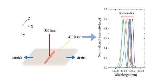
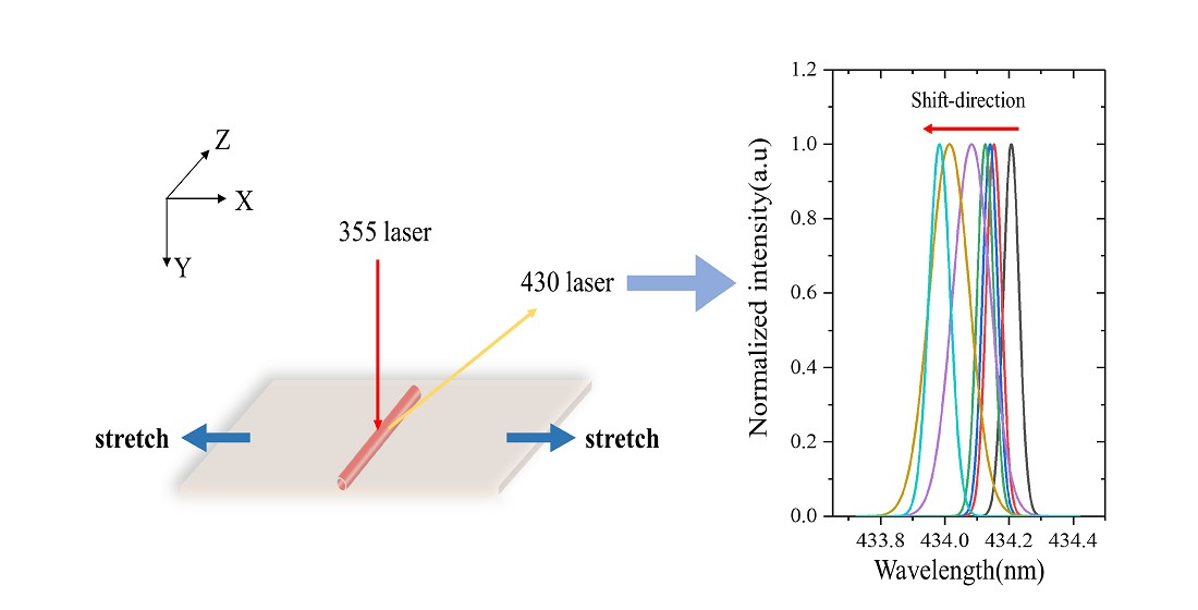
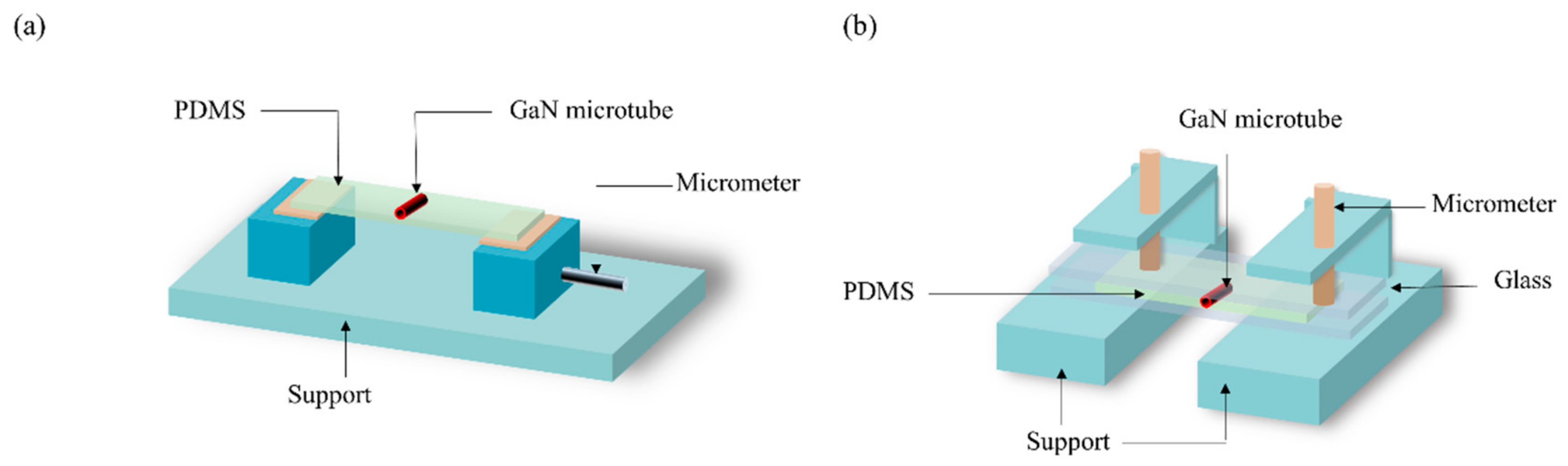
Figure 2a shows a schematic diagram of experimental setup for the strain test in the X and Z directions. The microtube embedded in the flexible PDMS substrate was fixed on a micrometer table, through which we could adjust the magnitude, as well as the direction, of the force. To test the strain in the Y direction, the flexible substrate was fixed to the center of two pieces of glass, as shown in Figure 2b. By applying force to the glass in the vertical direction, compressive strain could be generated in the microtubes. Spectra of the GaN microtubes were collected in a micro-photoluminescence (PL) setup, in which an objective lens served the function of optical excitation, as well as PL signal collection. A 355-nm diode laser with a 350-ps pulse time and 1000 Hz pulse frequency was used as the excitation source at room temperature. The laser spot could be focused down to a diameter of 20 μm on the surface of the microtube.
3. Results and Discussion
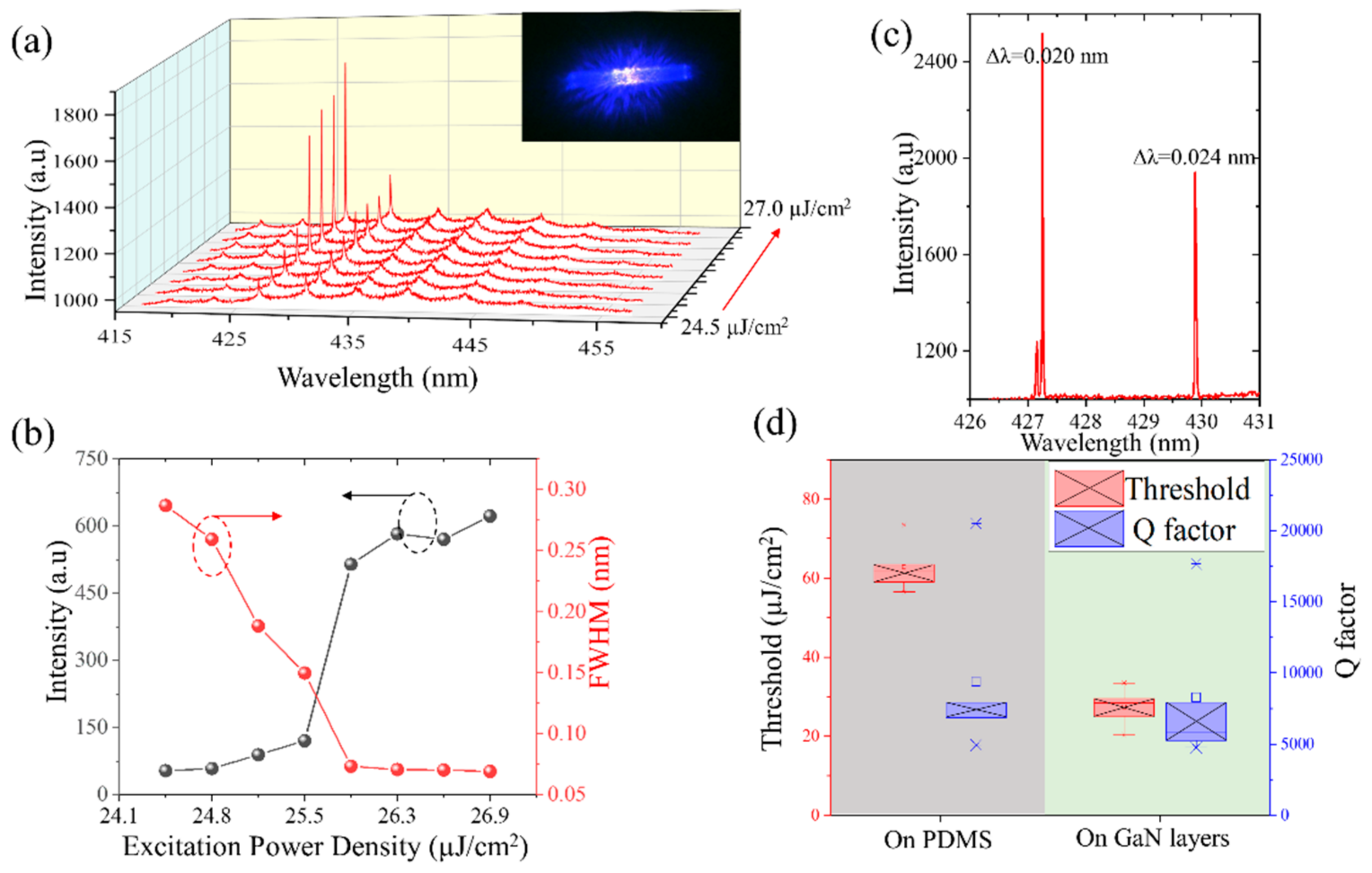
Figure 3a shows the PL spectra of a microtube in PDMS, which was excited from 24.5 μJ/cm2 to 27.0 μJ/cm2. All spectra correspond to the TM polarization mode due to the fact that the TE mode was not sustainable for such thin-walled microcavities [32]. The optical mode separation (free spectral range (FSR)) was measured at around 4.0 nm when was 430 nm, which matched the calculations using the periodic boundary condition . In this equation, R represents the radius of the microtubule, λ represents the wavelength of the laser, represents the effective refractive index of the microtube material, and m represents the azimuthal mode number. As shown in Figure 3a we also found a series of resonant peaks at 419.03, 422.95, 426.79, 430.82, 435.07, 439.38 nm, etc., which correspond to successive azimuthal modes. As the pump energy increased, certain resonance modes, such at 426.79 nm and 430.82 nm, changed from spontaneous emission to stimulated emission. Figure 3b shows the PL intensity and full width at half maximum (FWHM) versus pump energy density for the 426.79-nm peak of the microtube in the PDMS substrate. When the threshold was reached, the linewidth of the resonance peak decreased from 0.29 nm to 0.07 nm, confirming the occurrence of stimulated emission. Figure 3c shows the PL spectrum of another microtube with a narrow FWHM of about 19.8 pm and 24.1 pm at 427.25 nm and 429.89 nm, and the corresponding Q factors are 21,578 and 17,837, respectively. Such numbers were considered large enough compared to other Q values of tubular microcavity that were reported previously [34,35,36]. Figure 3d shows a box-plot showing a comparison of the threshold and the Q factor between the PDMS and GaN substrates. To eliminate the individual difference, five microtubes were measured. The average threshold was reduced from 62.86 μJ/cm2 to 27.34 μJ/cm2 while the Q value fluctuated in a relatively large range, resulting in no significant difference before and after the transfer.
The Purcell effect describes the enhancement of spontaneous emission rate by the environment. In most cases, one can reduce the mode volume of a microcavity to lower the excitation threshold, which will also lead to an increase in the Purcell factor [37]. The effective mode volume of a microcavity is equal to the total electric field energy in the microcavity divided by the maximum electric field energy density. In addition to absorption by the GaN material and curvature-induced light scattering, light leakage through n-doped GaN and sapphire substrates also leads to an increase in the mode volume of the microcavity. When the pump energy was above the threshold, there was no obvious difference in the Q-factor of the GaN microtubes, with or without the transfer process. Thus, the threshold change is more likely caused by the changing of the mode volume. The mode volume was investigated using finite-different time-domain (FDTD) simulations with an embedded modal volume analysis tool for the confined mode. The GaN refractive index at 450 nm was set to be 2.4 while that of PDMS was set as 1.41.
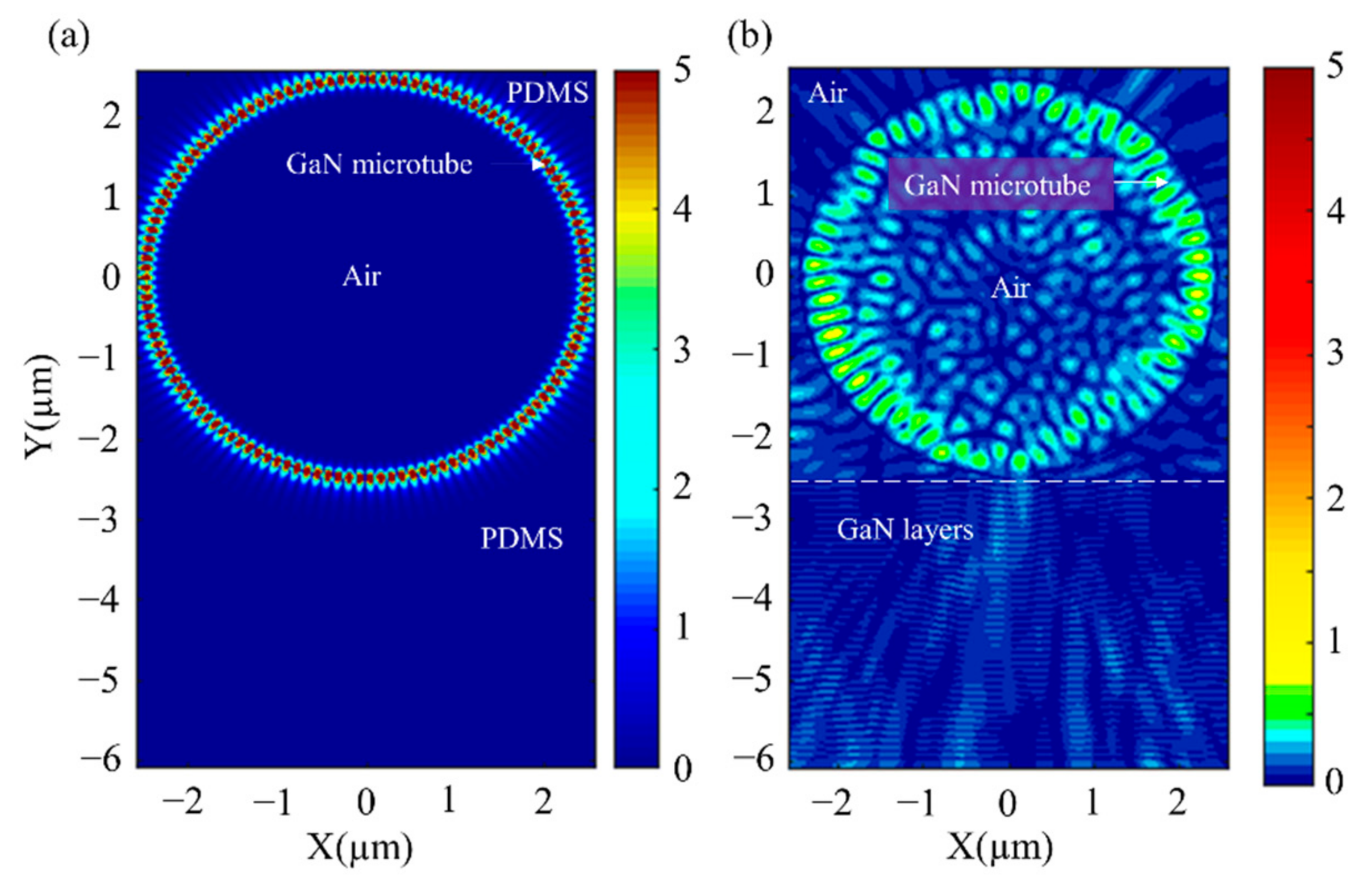
Figure 4a,b shows the electric field distribution inside the microtube embedded in the PDMS substrate, as well as on the GaN substrate, respectively. The amplitude of the electrical field intensity was indicated by the color bar. As the Figure 4a shows, light from the gain material (QWs) is limited by total internal reflection between the outer interface of GaN/PDMS and the inner interface of GaN/air. The mode volume of the microtube with GaN substrate was calculated to be ~1.32 × 10⁻³ μm3 by FDTD simulation while that of the microtube embedded in the PDMS substrate is ~6.92 × 10⁻⁴ μm3. The reduction of the mode volume caused the laser threshold to decrease from 62.86 μJ/cm2 to 27.34 μJ/cm2. From Figure 4b, one can see that light leaks through the GaN substrate underneath the microtube due to the lack of refractive index contrast. The proportional energy that leaked through the GaN layer substrate was as high as 11.03% of the total energy propagating in the system. The proportional energy that leaked through the PDMS substrate was about 1.21%. This was caused by the excessive refractive index difference between the PDMS layer and the GaN microtube.
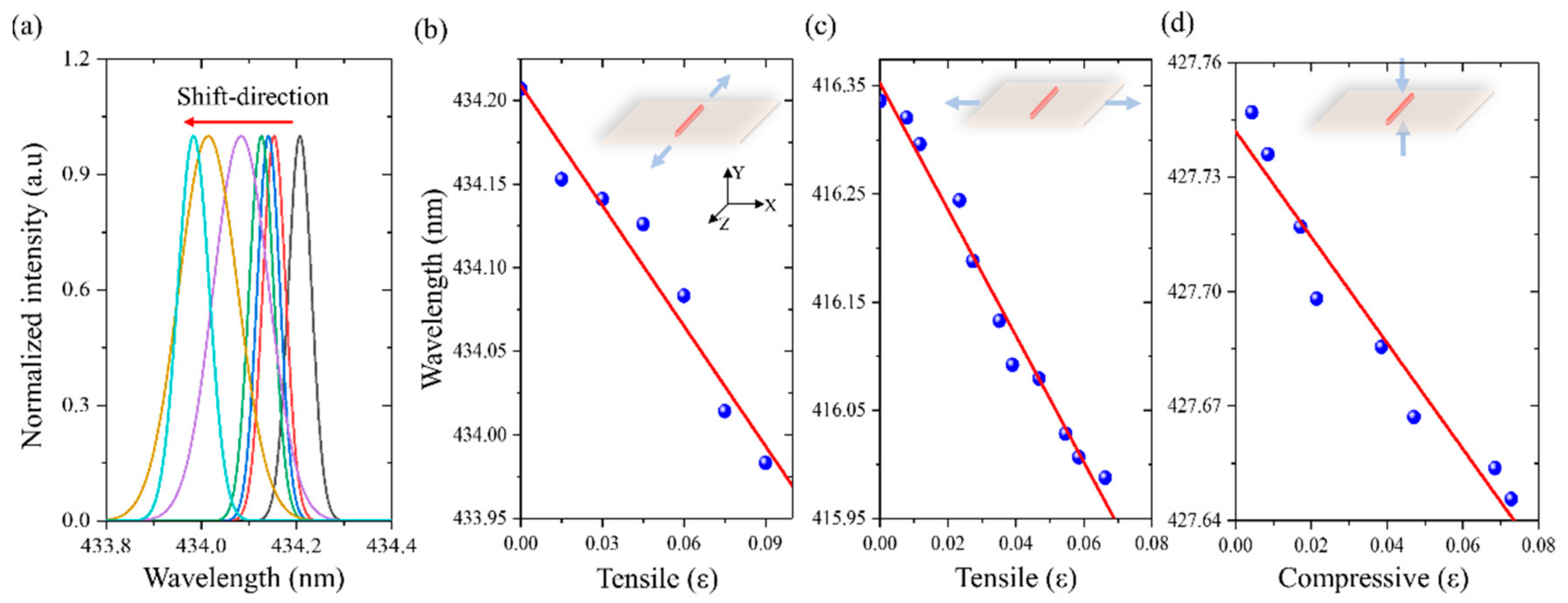
The measured PL spectra under stretching conditions in the Z direction are described in Figure 5a, in which the Z direction is defined as the axial direction while the cross section of the microtube is set in the X–Y plane. The geometrical deformation of the PDMS can be described as stretching unit ε, which was defined as Δd/d to describe the percentage change of the dimension. Parameter d is the original length of the substrate and Δd represents the deformation length under tensile forces. The wavelength shift as a function of stretching unit ε in Z direction is plotted in Figure 5b while that of the X and Y directions are shown in Figure 5c,d, respectively. We used the PL blue-shift per stretching unit as the detection sensitivity of the microtube strain sensor. The PL blue-shifts of the microtube are about 5.83, 1.38, and 2.39 nm per stretching unit in the X, Y, and Z directions, respectively. Simulation using FDTD (not shown) demonstrated that, as the strain on the PDMS substrate increased from 0 to 0.1, the OPSR of the laser emission decreased from 10.26 dB to 1.01 dB. According to the periodic boundary condition, the blue-shift was attributed to the change in the index of the surrounding PDMS material under different tensile stresses while the red-shift occurred under compressive strain [27,29]. However, in our work, both the tensile stress and compressive strain conditions led to a blue-shift. Thus, the deformation of micro-cavity should have played a role to counter balance in one way or another. Therefore, it is necessary to study how the deformation of a microcavity and the refractive index changes of PDMS affect the microtube wavelength shift all together from a system point of view. The structural deformations of the microcavity under strain were investigated by establishing a simulation model using finite-element analysis (FEA) software.
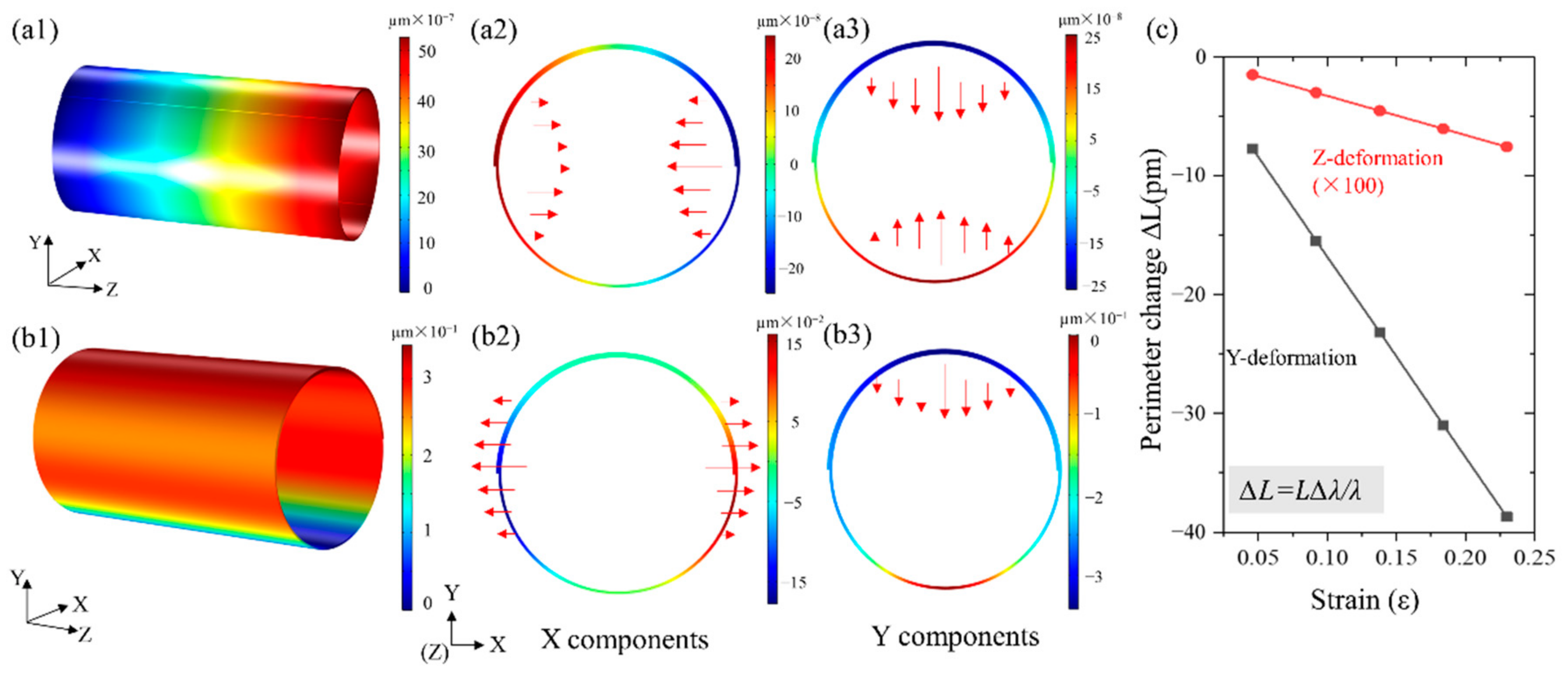
Figure 6(a1) shows the 3D deformation distribution under 0.05 ε tensile strain from the Z direction as if the microtube was stretched from the right end while fixing the left end. The cross-sectional deformation magnitude of the X and Y components are shown in Figure 6(a2,a3), respectively. The direction and the length of the arrow represent the direction and the magnitude of the deformation. The calculations show that the perimeter length (L) of the microtube decreases as the tensile strain increases. The changed length (∆L) can be calculated by: where ∆λ represents the blue-shift. Figure 6c shows the numerical simulation results of the microtubule circumference variations with applied strain. The ∆L in the Z direction was calculated and the corresponding to the per stretching unit was 0.09 nm. In the same way, we could simulate the deformation distribution under 0.05 ε tensile strain, as if the microtube was pressed from the top while fixing the bottom (Figure 6(b1)). The cross-sectional deformation magnitude of the X component and Y component are show in Figure 6(b2,b3), respectively. Due to the rotational symmetry in the X–Y plane blue-shift per stretching unit by strain in the both X and Y direction show the same value of 4.60 nm/ε while the value in the Z direction is 0.09 nm/ε. Blue-shift per stretching unit in the X, Y, and Z directions were measured as 5.83, 1.38 and 2.39 nm/ε, respectively. The discrepancy between the calculations and measurements can be attributed to the refractive index change of the PDMS alone. The variation introduced by the PDMS could be estimated as 2.23 nm/ε ((5.83 nm/ε − 1.38 nm/ε)/2), meaning that when PDMS stretched one unit of strain, the change in the refractive index will lead to a blue-shift of 2.23 nm/ε. The measured blue-shift with an applied force in the Z direction should be attributed to both the index change of the PDMS and the deformation of the microtube. The total per stretching unit in the simulation was about 2.32 nm/ε (2.23 nm/ε from PDMS and 0.09 nm/ε from microtube), which was very close to the experimental result of 2.39 nm/ε. Presently, we proved that the stress-induced blue-shift was caused by deformation of both the microtube and the PDMS. This helps us to better design and characterize a strain sensor with an ultra-thin microtube cavity in a flexible substrate.
4. Conclusions
In summary, a blue QW-based ultra-thin WGM microtube cavity was fabricated and successfully transferred to a PDMS matrix. The removal of the native GaN substrate and the ultra-thin wall thickness enabled a reduced mode volume. This leads to a smaller threshold of 25.55 µJ/cm2 while a high-quality factor of >15,000 was obtained compared to that before the transfer. By comparing the measured and simulated results, we found that the strain sensitivity was, not only affected by the deformation of the microtube, but also affected by the refractive index change caused by PDMS deformation. Both effects are suggested to be carefully considered in strain sensor design and characterization. This tunable low-threshold tubular microcavity hold, protected by the PDMS, may help to realize small mode volume light sources that are needed in advanced strain sensors for multiple purposes and complex environments.
Author Contributions
Conceptualization, P.H.; methodology, P.H., S.Z. and Z.T.; validation, P.H. and Y.Z.; investigation, Y.L.; resources, F.Y.; writing—original draft preparation, P.H.; writing—review and editing, Y.L.; visualization, Y.L.; supervision, F.Y. All authors have read and agreed to the published version of the manuscript.
Funding
This research was funded by the National Key Research and Development Program of China (2016YFB0400801) and the Fundamental Research Funds for the Central Universities (Z201805198).
Data Availability Statement
The data used to support the findings of this study are included within the article. However, the corresponding author can provide the data used in this study upon request.
Acknowledgments
Thanks to the International Centre for Dielectric Research at Xi’an Jiaotong University for their help with the electron microscopy experiments.
Conflicts of Interest
The authors declare no conflict of interest.
References
- Byun, J.; Lee, Y.; Yoon, J.; Lee, B.; Oh, E.; Chung, S.; Lee, T.; Cho, K.-J.; Kim, J.; Hong, Y. Electronic skins for soft, compact, reversible assembly of wirelessly activated fully soft robots. Sci. Robot. 2018, 3, eaas9020. [Google Scholar] [CrossRef] [PubMed] [Green Version]
- Yang, J.C.; Mun, J.; Kwon, S.Y.; Park, S.; Park, S. Electronic Skin: Electronic Skin: Recent Progress and Future Prospects for Skin-Attachable Devices for Health Monitoring, Robotics, and Prosthetics (Adv. Mater. 48/2019). Adv. Mater. 2019, 31, 1970337. [Google Scholar] [CrossRef]
- Meacham, K.W.; Giuly, R.J.; Liang, G.; Hochman, S.; Deweerth, S.P. A lithographically-patterned, elastic multi-electrode array for surface stimulation of the spinal cord. Biomed. Microdevices 2008, 10, 259–269. [Google Scholar] [CrossRef] [Green Version]
- Hua, Q.; Sun, J.; Liu, H.; Bao, R.; Yu, R.; Zhai, J.; Pan, C.; Wang, Z.L. Skin-inspired highly stretchable and conformable matrix networks for multifunctional sensing. Nat. Commun. 2018, 9, 244. [Google Scholar] [CrossRef]
- Chen, T.; Shi, Q.; Zhu, M.; He, T.; Yang, Z.; Liu, H.; Sun, L.; Yang, L.; Lee, C. Intuitive-augmented human-machine multidimensional nano-manipulation terminal using triboelectric stretchable strip sensors based on minimalist design. Nano Energy 2019, 60, 440–448. [Google Scholar] [CrossRef]
- Larson, C.; Peele, B.; Li, S.; Robinson, S.; Totaro, M.; Beccai, L.; Mazzolai, B.; Shepherd, R. Highly stretchable electroluminescent skin for optical signaling and tactile sensing. Science 2016, 351, 1071–1074. [Google Scholar] [CrossRef] [PubMed] [Green Version]
- Liang, J.J.; Li, L.; Tong, K.; Ren, Z.; Hu, W.; Niu, X.F.; Chen, Y.S.; Pei, Q.B. Silver Nanowire Percolation Network Soldered with Graphene Oxide at Room Temperature and Its Application for Fully Stretchable Polymer Light-Emitting Diodes. ACS Nano 2014, 8, 1590–1600. [Google Scholar] [CrossRef] [PubMed]
- Lv, Z.S.; Tang, Y.X.; Zhu, Z.Q.; Wei, J.Q.; Li, W.L.; Xia, H.R.; Jiang, Y.; Liu, Z.Y.; Luo, Y.F.; Ge, X.; et al. Honeycomb-Lantern-Inspired 3D Stretchable Supercapacitors with Enhanced Specific Areal Capacitance. Adv. Mater. 2018, 30, e1805468. [Google Scholar] [CrossRef]
- Kang, S.; Hong, S.Y.; Kim, N.; Oh, J.; Park, M.; Chung, K.Y.; Lee, S.S.; Lee, J.; Son, J.G. Stretchable Lithium-Ion Battery Based on Re-entrant Micro-honeycomb Electrodes and Cross-Linked Gel Electrolyte. ACS Nano 2020, 14, 3660–3668. [Google Scholar] [CrossRef]
- Emaminejad, S.; Gao, W.; Wu, E.; Davies, Z.A.; Nyein, H.Y.; Challa, S.; Ryan, S.P.; Fahad, H.M.; Chen, K.; Shahpar, Z. Autonomous sweat extraction and analysis applied to cystic fibrosis and glucose monitoring using a fully integrated wearable platform. Proc. Natl. Acad. Sci. USA 2017, 114, 4625–4630. [Google Scholar] [CrossRef] [PubMed] [Green Version]
- Gao, W.; Emaminejad, S.; Nyein, H.; Challa, S.; Chen, K.; Peck, A.; Fahad, H.M.; Ota, H.; Shiraki, H.; Kiriya, D. Fully integrated wearable sensor arrays for multiplexed in situ perspiration analysis. Nature 2016, 529, 509–514. [Google Scholar] [CrossRef] [Green Version]
- Nyein, H.Y.Y.; Tai, L.-C.; Quynh Phuong, N.; Chao, M.; Zhang, G.B.; Gao, W.; Bariya, M.; Bullock, J.; Kim, H.; Fahad, H.M.; et al. A Wearable Microfluidic Sensing Patch for Dynamic Sweat Secretion Analysis. ACS Sens. 2018, 3, 944–952. [Google Scholar] [CrossRef] [PubMed]
- Sun, T.-M.; Wang, C.-S.; Liao, C.-S.; Lin, S.-Y.; Perumal, P.; Chiang, C.-W.; Chen, Y.-F. Stretchable Random Lasers with Tunable Coherent Loops. ACS Nano 2015, 9, 12436–12441. [Google Scholar] [CrossRef] [PubMed]
- Liao, Y.M.; Lai, Y.C.; Perumal, P.; Liao, W.C.; Chang, C.Y.; Liao, C.S.; Lin, S.Y.; Chen, Y.F. Highly Stretchable Label-like Random Laser on Universal Substrates. Adv. Mater. Technol. 2016, 1, 7. [Google Scholar] [CrossRef]
- Hu, H.W.; Haider, G.; Liao, Y.M.; Roy, P.K.; Ravindranath, R.; Chang, H.T.; Lu, C.H.; Tseng, C.Y.; Lin, T.Y.; Shih, W.H.; et al. Wrinkled 2D Materials: A Versatile Platform for Low-Threshold Stretchable Random. Adv. Mater. 2017, 29, 10. [Google Scholar] [CrossRef] [Green Version]
- Kang, D.; Chen, H.; Yoon, J. Stretchable, skin-conformal microscale surface-emitting lasers with dynamically tunable spectral and directional selectivity. Appl. Phys. Lett. 2019, 114, 041103. [Google Scholar] [CrossRef]
- Zhou, T.; Liu, X.; Cui, Y.; Cheng, Y.; Fang, X.; Zhang, W.; Xiang, B.; Zhang, Z. Cantilever-based microring lasers embedded in a deformable substrate for local strain gauges. AIP Adv. 2018, 8, 075306. [Google Scholar] [CrossRef]
- Guo, J.; Zhao, K.; Zhou, B.; Ning, W.; Jiang, K.; Yang, C.; Kong, L.; Dai, Q. Wearable and Skin-Mountable Fiber-Optic Strain Sensors Interrogated by a Free-Running, Dual-Comb Fiber Laser. Adv. Opt. Mater. 2019, 7, 1900086. [Google Scholar] [CrossRef]
- He, L.; Özdemir, Ş.K.; Yang, L. Whispering gallery microcavity lasers. Laser Photonics Rev. 2013, 7, 60–82. [Google Scholar] [CrossRef]
- Li, K.H.; Cheung, Y.F.; Choi, H.W. Tunable GaN Photonic Crystal and Microdisk on PDMS Flexible Films. ACS Appl. Electron. Mater. 2019, 1, 1112–1119. [Google Scholar] [CrossRef]
- Zhang, Y.; Ryu, S.-W.; Yerino, C.; Leung, B.; Sun, Q.; Song, Q.; Cao, H.; Han, J. A conductivity-based selective etching for next generation GaN devices. Phys. Status Solidi B Basic Solid State Phys. 2010, 247, 1713–1716. [Google Scholar] [CrossRef]
- Holder, C.O.; Leonard, J.T.; Farrell, R.M.; Cohen, D.A.; Yonkee, B.; Speck, J.S.; DenBaars, S.P.; Nakamura, S.; Feezell, D.F. Nonpolar III-nitride vertical-cavity surface emitting lasers with a polarization ratio of 100% fabricated using photoelectrochemical etching. Appl. Phys. Lett. 2014, 105, 031111. [Google Scholar] [CrossRef]
- Elafandy, R.T.; Majid, M.A.; Ng, T.K.; Zhao, L.; And, D.C.; Ooi, B.S. Exfoliation of Threading Dislocation-Free, Single-Crystalline, Ultrathin Gallium Nitride Nanomembranes. Adv. Funct. Mater. 2014, 24, 2305–2311. [Google Scholar] [CrossRef] [Green Version]
- Lee, K.; Lee, J.; Hwang, H.; Reitmeier, Z.; Davis, R.; Rogers, J.; Nuzzo, R. A Printable Form of Single-Crystalline Gallium Nitride for Flexible Optoelectronic Systems. Small 2010, 1, 1164–1168. [Google Scholar] [CrossRef] [PubMed]
- Zhang, Y.; Sun, Q.; Leung, B.; Simon, J.; Lee, M.L.; Han, J. The fabrication of large-area, free-standing GaN by a novel nanoetching process. Nanotechnology 2011, 22, 2362–2365. [Google Scholar] [CrossRef] [PubMed]
- Shih, M.H.; Hsu, S.; Wang, Y.C.; Yang, Y.C.; Tsai, S.K.; Liu, Y.C.; Chang, Z.C.; Wu, M.C. Flexible compact microdisk lasers on a polydimethylsiloxane (PDMS) substrate. Opt. Express 2009, 17, 991–996. [Google Scholar] [CrossRef]
- Chen, R.; Ta, V.D.; Sun, H. Bending-Induced Bidirectional Tuning of Whispering Gallery Mode Lasing from Flexible Polymer Fibers. ACS Photonics 2014, 1, 11–16. [Google Scholar] [CrossRef]
- Yang, S.; Eugene, T.Y.K.; Wang, Y.; Zhao, X.; Demir, H.V.; Sun, H. Wavelength tuning of the spirally drawn whispering gallery mode microfiber lasers and the perspectives for sensing applications. Opt. Express 2017, 25, 2618–2626. [Google Scholar] [CrossRef] [PubMed] [Green Version]
- Zhou, T.; Zhou, J.; Cui, Y.; Liu, X.; Li, J.; He, K.; Fang, X.; Zhang, Z. Microscale local strain gauges based on visible micro-disk lasers embedded in a flexible substrate. Opt. Express 2018, 26, 16797–16804. [Google Scholar] [CrossRef] [PubMed]
- Peng, Y.; Lu, J.; Peng, D.; Ma, W.; Li, F.; Chen, Q.; Wang, X.; Sun, J.; Liu, H.; Pan, C. Dynamically Modulated GaN Whispering Gallery Lasing Mode for Strain Sensor. Adv. Funct. Mater. 2019, 29, 1905051. [Google Scholar] [CrossRef]
- Wang, J.; Zhan, T.; Huang, G.; Chu, P.K.; Mei, Y. Optical microcavities with tubular geometry: Properties and applications. Laser Photonics Rev. 2014, 8, 521–547. [Google Scholar] [CrossRef]
- Li, Y.; Feng, L.; Su, X.; Li, Q.; Yun, F.; Yuan, G.; Han, J. Whispering gallery mode lasing from InGaN/GaN quantum well microtube. Opt. Express 2017, 25, 18072–18080. [Google Scholar] [CrossRef]
- Li, Y.; Hu, P.; Feng, L.; Du, M.; Su, X.; Li, Q.; Yun, F. InGaN microtube optical resonator with sub-wavelength wall thickness and its application to refractive index sensing. J. Appl. Phys. 2019, 126, 075708. [Google Scholar] [CrossRef]
- Maqbool, M.; Main, K.; Kordesch, M. Titanium-doped sputter-deposited AlN infrared whispering gallery mode microlaser on optical fibers. Opt. Lett. 2010, 35, 3637–3639. [Google Scholar] [CrossRef] [PubMed]
- Venkataramudu, U.; Venkatakrishnarao, D.; Chandrasekhar, N.; Mohiddon, M.A.; Chandrasekar, R. Single-particle to single-particle transformation of an active type organic mu-tubular homo-structure photonic resonator into a passive type hetero-structure resonator. Phys. Chem. Chem. Phys. 2016, 18, 15528–15533. [Google Scholar] [CrossRef] [PubMed]
- Coulon, P.M.; Pugh, J.R.; Athanasiou, M.; Kusch, G.; Le Boulbar, E.D.; Sarua, A.; Smith, R.; Martin, R.W.; Wang, T.; Cryan, M.; et al. Optical properties and resonant cavity modes in axial InGaN/GaN nanotube microcavities. Opt. Express 2017, 25, 28246–28257. [Google Scholar] [CrossRef] [Green Version]
- Khurgin, J.B.; Noginov, M.A. How Do the Purcell Factor, the Q-Factor, and the Beta Factor Affect the Laser Threshold? Laser Photonics Rev. 2021, 15, 2000250. [Google Scholar] [CrossRef]
Figure 1.
Optical images of (a) arrays of microtubes on GaN layers and (b) arrays of microtubes in PDMS film. (c) Side view of SEM image of microtubes with 57-nm wall thickness.
Figure 1.
Optical images of (a) arrays of microtubes on GaN layers and (b) arrays of microtubes in PDMS film. (c) Side view of SEM image of microtubes with 57-nm wall thickness.

Figure 2.
Schematic diagram of the experimental setup for the strain test: (a) tensile force in the X and Z directions and (b) compressive force in the Y direction.
Figure 2.
Schematic diagram of the experimental setup for the strain test: (a) tensile force in the X and Z directions and (b) compressive force in the Y direction.

Figure 3.
(a) PL emission spectra of microtube in PDMS under an energy density from 24.5 μJ/cm2 to 27.0 μJ/cm2, the inset is an optical image, captured by the CCD, of a microtube pumped above the laser threshold. (b) The intensity of PL (black) and FWHM (red) as a function of the excitation energy density for the microtubes embedded in a PDMS film. (c) The PL spectrum of microtube with a narrow linewidth. (d) The box-plot is the threshold and Q factor of microtubes in PDMS or on the GaN layer.

Figure 4.
(a) Electrical field distribution inside the microtube cavity embedded in a flexible substrate. (b) Electrical field distribution inside the microtube cavity with GaN layers.
Figure 4.
(a) Electrical field distribution inside the microtube cavity embedded in a flexible substrate. (b) Electrical field distribution inside the microtube cavity with GaN layers.

Figure 5.
(a) PL spectra in the Z direction measured under different stretching conditions from 0 to 0.09 ε. (b–d) show the measured lasing wavelength changing under various tensile conditions in the Z and X directions and compressive conditions in the Y direction, respectively. The insets in (b–d) show the direction of applied force.

Figure 6.
(a1) The 3D deformation distribution under 0.05 ε tensile strain from the Z direction. (a2,a3) the cross-sectional deformation magnitude of the X component and the Y component, respectively. (b1) The 3D deformation distribution under −0.05 ε compressive strain from the Z direction. (b2,b3) the cross-sectional deformation magnitude of the X component and the Y components, respectively. (c) Simulated microtubule circumference variation as a function of applied strain.

Publisher’s Note: MDPI stays neutral with regard to jurisdictional claims in published maps and institutional affiliations. |
© 2021 by the authors. Licensee MDPI, Basel, Switzerland. This article is an open access article distributed under the terms and conditions of the Creative Commons Attribution (CC BY) license (https://creativecommons.org/licenses/by/4.0/).
Share and Cite
MDPI and ACS Style
Hu, P.; Li, Y.; Zhang, S.; Zhang, Y.; Tian, Z.; Yun, F. Low-Threshold and Wavelength-Tunable InGaN Tubular WGM Laser Embedded in a Flexible Substrate. Crystals 2021, 11, 1251. https://0-doi-org.brum.beds.ac.uk/10.3390/cryst11101251
AMA Style
Hu P, Li Y, Zhang S, Zhang Y, Tian Z, Yun F. Low-Threshold and Wavelength-Tunable InGaN Tubular WGM Laser Embedded in a Flexible Substrate. Crystals. 2021; 11(10):1251. https://0-doi-org.brum.beds.ac.uk/10.3390/cryst11101251
Chicago/Turabian StyleHu, Peng, Yufeng Li, Shengnan Zhang, Ye Zhang, Zhenhuan Tian, and Feng Yun. 2021. "Low-Threshold and Wavelength-Tunable InGaN Tubular WGM Laser Embedded in a Flexible Substrate" Crystals 11, no. 10: 1251. https://0-doi-org.brum.beds.ac.uk/10.3390/cryst11101251
Note that from the first issue of 2016, this journal uses article numbers instead of page numbers. See further details here.