
Wear Behavior of Commercial Copper-Based Aircraft Brake Pads Fabricated under Different SPS Conditions


1
Research Institute of Advanced Manufacturing and Materials Technology, Korea Institute of Industrial Technology, Incheon 21999, Korea
2
Department of Materials Science and Engineering, Research Institute of Advanced Materials, Seoul National University, Seoul 08826, Korea
*
Author to whom correspondence should be addressed.
†
These authors contributed equally to this work.
Crystals 2021, 11(11), 1298; https://0-doi-org.brum.beds.ac.uk/10.3390/cryst11111298
Submission received: 7 October 2021
/
Revised: 21 October 2021
/
Accepted: 25 October 2021
/
Published: 26 October 2021
(This article belongs to the Special Issue Deformation and Microstructural Evolution of Copper Alloy)
Abstract
:Understanding the wear behavior of Cu-based brake pads, which are used in high-speed railway trains and aircraft, is essential for improving their design and safety. Therefore, the wear mechanism of these pads has been studied extensively. However, most studies have focused on the changes in their composition and not the effects of their manufacturing conditions. In this study, we fabricated commercial Cu-based brake pads containing Fe, graphite, Al2O3, and SiO2 using spark plasma sintering under different conditions. The microstructures and mechanical properties of the pads were investigated. The pads were tribo-evaluated using the ball-on-disc test under various load conditions. Their worn surfaces were analyzed using X-ray diffraction analysis, scanning electron microscopy, energy-dispersive X-ray spectroscopy, and confocal microscopy in order to elucidate their wear mechanism. In addition, the dynamometer test was performed to confirm whether their wear behavior would be similar under actual conditions. Finally, a comparative analysis was performed using the ball-on-disc test. The results indicated that the brake pads with the same composition but fabricated under different sintering conditions exhibited different wear characteristics. We believe that this research is of great significance for understanding the wear mechanism of Cu-based brake pads and improving their design and hence their performance.
1. Introduction
Cu-based sintered materials are the most widely used friction materials for aircraft and high-speed train brake systems owing to their high thermal conductivity, wear resistance, and thermal stability [1,2,3]. In fact, the indirect wear resistance and service life indicators of H (Hardness)/E (Reduced Young’s modulus) and H3/E2 in nano-indentation were obtained in moderate values of ~0.047 and ~0.017, respectively, in Cu-based sintered materials [4,5,6]. Also, compared to competitive organic-based brake pads, which experience the deterioration of friction materials at high service temperature and are limited to general usage under ~300 °C, Cu-based sintered materials easily withstand high temperature over ~1000 °C [7]. However, Cu-based sintered materials suffer from low hardness and undergo mechanical softening during high-temperature wear [8,9]. To overcome these disadvantages, which can have an adverse effect on properties such as the heat conductivity, it has been proposed that abrasive components such as Fe, CrFe, SiO2, Al2O3, and SiC particles, which show high hardness, be mixed in the metal matrix for mechanical strengthening and increasing the friction coefficient [3,10,11,12,13,14]. In addition, layered solid lubricants, namely, graphite or MoS2, are added to sintered composites to stabilize their friction coefficient and reduce their wear loss [15,16,17]. Consequently, Cu-based sintered composites containing matrix-strengthening metallic phases, oxide abrasives, and graphite lubricants have been suggested for use in industrial-scale applications requiring high braking energy density (250–450 J/mm2) [18,19,20,21].
Typically, sintered Cu–metal-matrix composite (Cu–MMC) exhibits excellent stable coefficient of friction (COF) of 0.3 to 0.4, which are the suggested values for industrial-scale high braking energy density pad applications, up to ~350 km/h braking speed. However, continuous generation of high braking energy density inevitably leads to high flashing temperature on brake pad surface and eventually mechanical failure. Thus, recent studies of Cu–MMC brake pads focused in particular on the mechanical failure behavior of Cu–MMC under high-temperature braking test or the effect of abrasive or lubricant compositions on Cu–MMC in order to produce stable Cu–MMC with longstanding braking capabilities under high temperature up to ~800 °C. For example, Zhang et al. [8] investigated the effect of high temperature on wear behavior of Cu–MMC and revealed that a solid graphite lubricant fragment at high temperature around 800 °C induced severe wear loss and unstable COF. Also, in order to figure out the wear behavior of Cu–MMC under severe wear condition, microstructure evolution and the tribofilm formation mechanism under ~380 km/h braking speed was studied [19,22]. Aside from mechanical failure studies, modification of composition such as Fe [10], MoS2 [23], or carbon fiber [24] has recently been studied for improving sustainability of tribological properties under severe wear condition of high temperature and braking speed.
In particular, the wear mechanism of Cu–MMC has been investigated extensively among those studies. Akhtar et al. [25] studied the processing, microstructure, mechanical properties, electrical conductivity, and wear behavior of high-volume titanium-carbide-reinforced Cu–MMC. Gupta et al. [26] elucidated the dependence of the wear behavior of iron–alumina–metal-matrix nanocomposites prepared by powder metallurgy on the sintering mechanism. Xiao et al. [19] also studied the microstructure, mechanical properties, and tribological behavior of a powder metallurgy-processed Cu–metal-matrix composite. It has been reported that delamination and oxidation are the dominant wear mechanisms of Cu–MMCs, which exhibit excellent wear resistance. Zhan and Zhang [27] investigated the dry sliding friction and wear behaviors of Cu-matrix composites reinforced with SiC and graphite particles. They showed that a continuous supply of graphite to the tribosurface is an important precondition for the formation of a graphite-rich mechanical mixed layer, which exhibits antifriction properties.
As mentioned above, previous studies have primarily focused on the effects of the composite composition on the wear behavior. However, efforts are underway to also study the effects of the manufacturing conditions of commercial pads containing Fe, SiO2, Al2O3, and graphite on their wear mechanism. Even when the same powder is used, the processing temperature and pressure will have a determining effect on the material properties and hence the tribological behavior. Hence, processing techniques such as spark plasma sintering (SPS) or microwave sintering also could vary densification procedures of as-prepared powder materials. Generally, SPS produces the fast one-step sintering with high densification rate by inter-bonding of Cu particles from high electrical pulse and elimination of surface oxides [28,29]. Similarly, microwave sintering also presents high densification rates of powders from uniform and fast sintering by electromagnetic waves [30]. As a result, high mechanical strength of MMC was achieved in SPS [31] and microwave sintering [30] compared to conventional sintering. From an industrial viewpoint, it is particularly important to understand the effects of the manufacturing conditions on the wear behavior and optimize the coefficient of friction. However, for this, the dynamometer test, which involves high energy levels (greater than 7.5 MJ) and is used widely in the industry [32], is not appropriate. This is because the test sample undergoes severe damage during the dynamometer test, and it is not feasible to analyze the worn sample surface. Therefore, it is necessary to test the wear mechanism under low-energy wear conditions using a ball-on-a-disc or pin-on-a-disc apparatus and correlate the results with those of higher-energy dynamometry for industrial-scale applications.
In this study, we first performed ball-on-disc tests using loads of 3, 5, and 10 N to elucidate the wear mechanism of Cu-based brake pads fabricated under different sintering (temperature and pressure) conditions. The fabricated friction specimens were then analyzed and their properties, including their microstructure, phase composition, and microhardness, were compared. After the tribological tests, the variation in the COF was analyzed, and the worn surfaces were characterized to determine the wear mechanism. In addition, the dynamometer test was performed to verify whether high-energy wear occurs through a wear mechanism similar to that for low-energy wear during the ball-on-disc test.
2. Materials and Methods
2.1. Sample Preparation
The Cu-based brake pad samples used in this study were fabricated by spark plasma sintering. The composition of the sample powder is 60–65 wt% of Cu, 3–5 wt% of Fe, 10–12 wt% of SiO2, 3–5 wt% of Al2O3, and 15–17 wt% of graphite, with theoretical density of the mixed powders was calculated as ~4.854. The SPS of the sample was conducted in a 20 ∅ graphite mold at a heating rate of ~50 °C/min. The pad samples were produced under different conditions to determine the effects of these conditions on the wear and friction properties. As shown in Table 1, three variables were considered: the temperature, which was set to 400, 600, 700, and 800 °C; the pressure, which was set to 20 and 40 MPa; and finally the holding time, which was set to 10 and 20 min. After the friction samples had been fabricated, their phase compositions were analyzed using X-ray diffraction (XRD) analysis (SmartLab, Rigaku, Japan). The density was measured by the Archimedes method, and the relative density was also calculated. To determine the macrohardness of the brake pad materials, the C R-scale Rockwell hardness (Wizhard HR-523, Mitutoyo, Japan) was measured, based on the ISO 6508-1:2016 standard. The hardness test was performed on five samples for each process condition, and the average hardness was calculated. The surface morphologies of the pads were examined by scanning electron microscopy (SEM, Quanta 200F, FEI, USA).
2.2. Tribological Test
A ball-on-disc tribometer (Standard Tribometer TRB, CSM Instruments, Switzerland) was used for the tribological test, which was performed as per ASTM G99. An SUS 304 ball (Ra of ~1m, diameter of 1 mm, HRC 58–59) was used as the rider and was pressed against the stationary brake pads fabricated in this study. Before the tribological test, the ball and the test specimens were cleaned with acetone and then dried. The surface roughness of the pad sample was ~Ra = 3.0 ± 1.0 μm. Surface roughness measurements on each sample were conducted for 5 times on average. The tribological test was performed under dry sliding conditions at 1000 rpm using a linear speed of 100 mm/s and applied normal loads of 3, 5, and 10 N. The test was repeated three times for each condition to ensure the accuracy and repeatability of the results. All the experiments were conducted at a temperature of 24.0 °C and atmospheric humidity of 50.0%.
To simulate the high-energy braking conditions, a laboratory-scale dynamometer (UNI-DYN100, UNI) was used to examine the braking performance. The pad used was a square-faced specimen (10 × 10 mm2) cut from the brake pad to be evaluated. The simulated brake disc was 115 mm in diameter and 12 mm in thickness and machined from an AMS 6385 steel plate. The wheel running speed was set to 60, 80, and 100 km/h, and during each experiment, the disc was stopped 20 times with a force of 300 N.
2.3. Analysis of Worn Surface
After the test, the roughness of the wear trace was inspected using confocal laser scanning microscopy (VK-X200K, Keyence, Japan), and the morphology, elemental composition, and phase composition of the worn surface and cross-sectional microstructure of the specimen were examined using SEM with energy-dispersive X-ray spectroscopy (EDS) and transmission electron microscopy (TEM, Tecnai G2 F20, FEI, USA). The TEM samples were prepared using the focused ion beam (FIB, NOVA200, FEI, USA) ion milling technique.
3. Results and Discussion
3.1. Characterization of Cu-Based Brake Pads
3.1.1. Composition and Microstructure
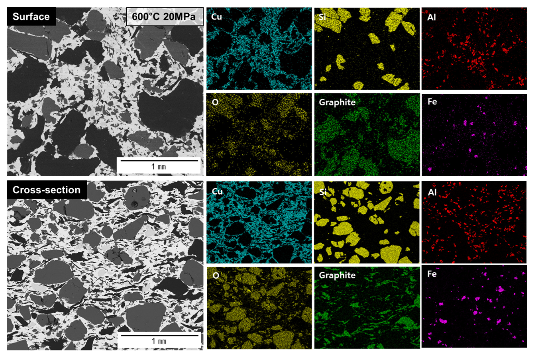
As shown in Table 1, we analyzed the pads formed at 600 °C–20 MPa (600-20), 800 °C–20 MPa (800-20), and 800 °C–40 MPa (800-40), as these pads show high relative densities among all the pads fabricated under the different conditions. Figure 1 shows an SEM image and the EDS analysis results for the 600-20 pad. The matrix of the pad is composed of Cu, and SiO2, Al2O3, graphite, and Fe phases are distributed within the Cu matrix. The size of the SiO2 phase i s 80–200 μm, and it acts as a friction material. The Al2O3 phase has a size of approximately 10–50 μm and also acts as a friction material. Finally, the Fe phase has a size of 10–90 μm and acts as a friction modifier. Graphite acts as a lubricant and, as shown in Figure 1, has a block-like shape on the surface. On the other hand, in the cross-section, it has a flake-like morphology. This is because it was pressurized during the SPS fabrication process and was also affected by the temperature. Finally, the Cu matrix plays the role of firmly fixing each phase.
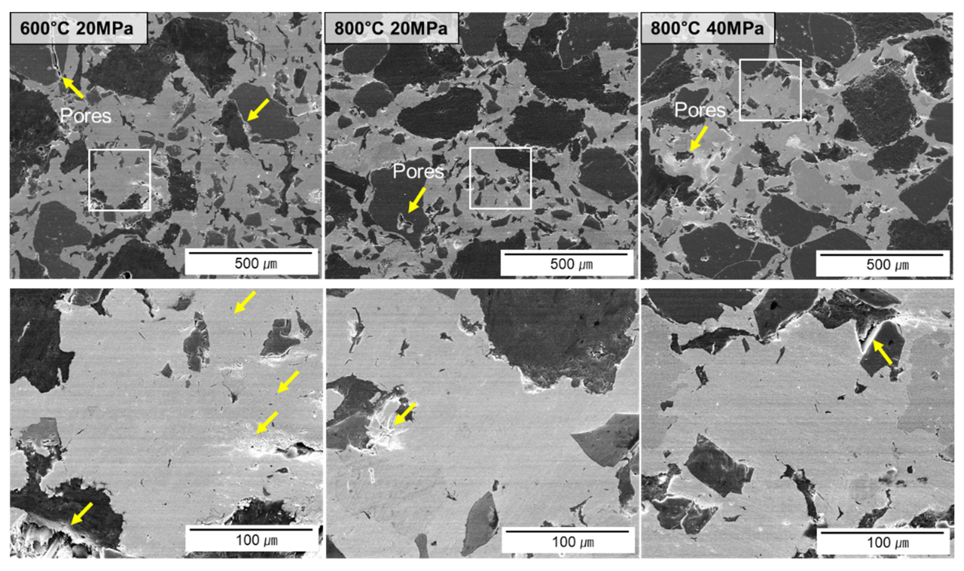
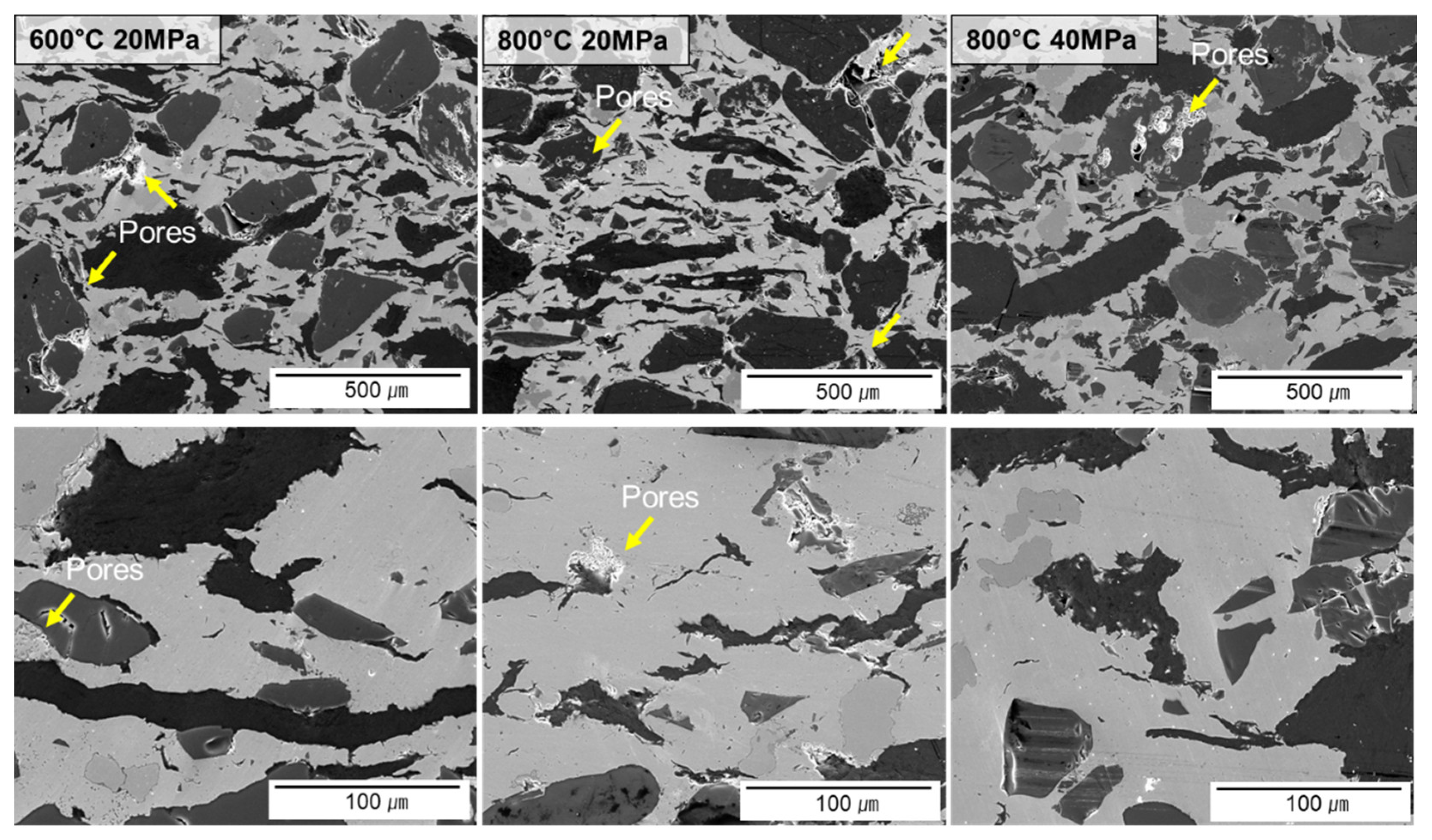
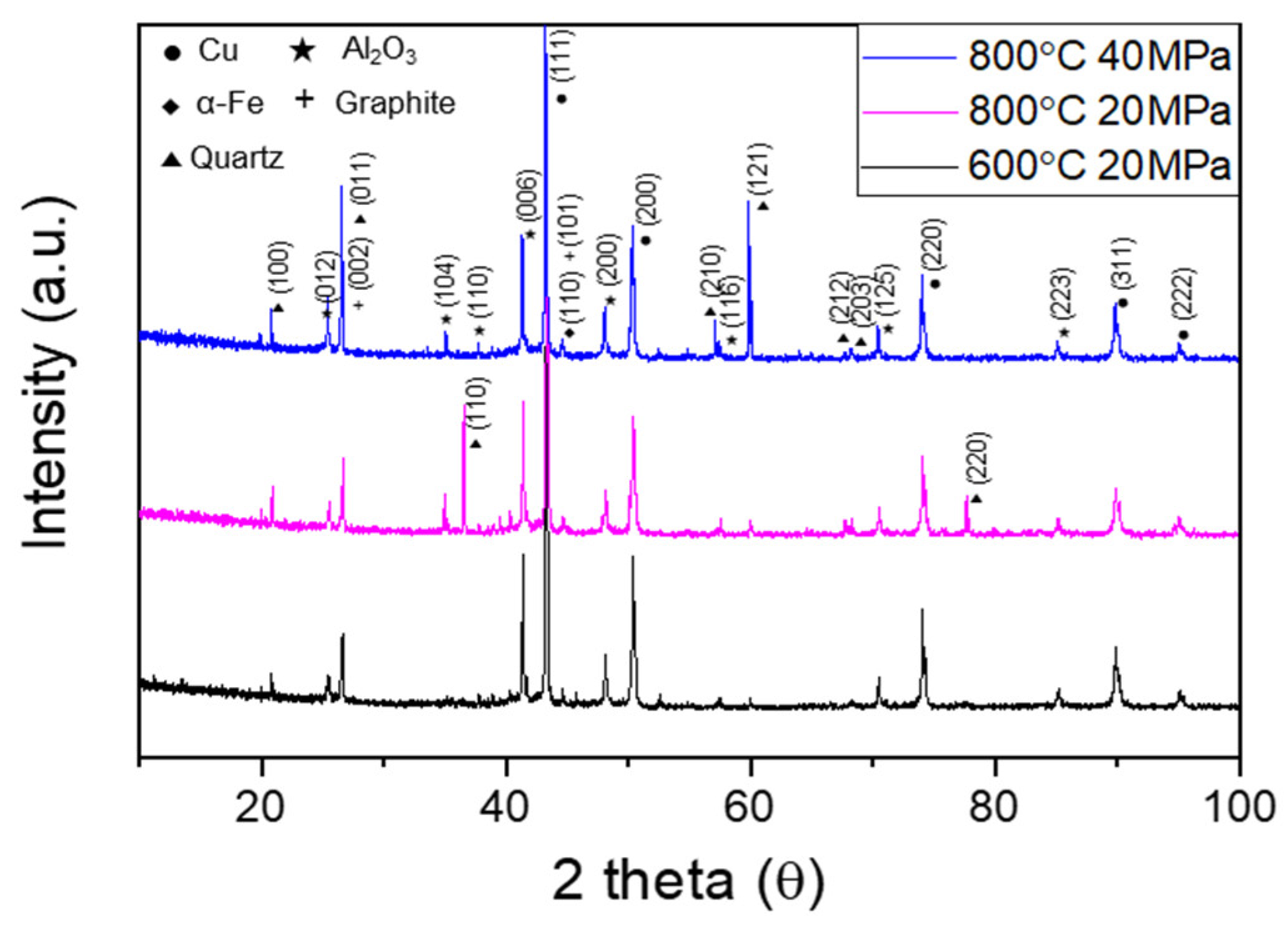
SEM images of the samples fabricated under the different conditions (600-20, 800-20, and 800-40) are shown in Figure 2. It can be seen that pores are present in all the specimens. In particular, a large number of pores are present in the 600-20 sample. These pores mainly formed around the oxide and graphite phases because of the weak coherency of these materials [33]. SEM images of the cross-sections are shown in Figure 3. As was also evident from Figure 1, graphite exists in the form of flakes, and pores are present around the oxide phases, which show weak coherency to the matrix. The XRD analysis results are shown in Figure 4; the analysis was performed to determine the overall compositions of the samples and determine whether the desired phases were formed. Although the samples were produced under different conditions, it can be seen that they have the same composition.
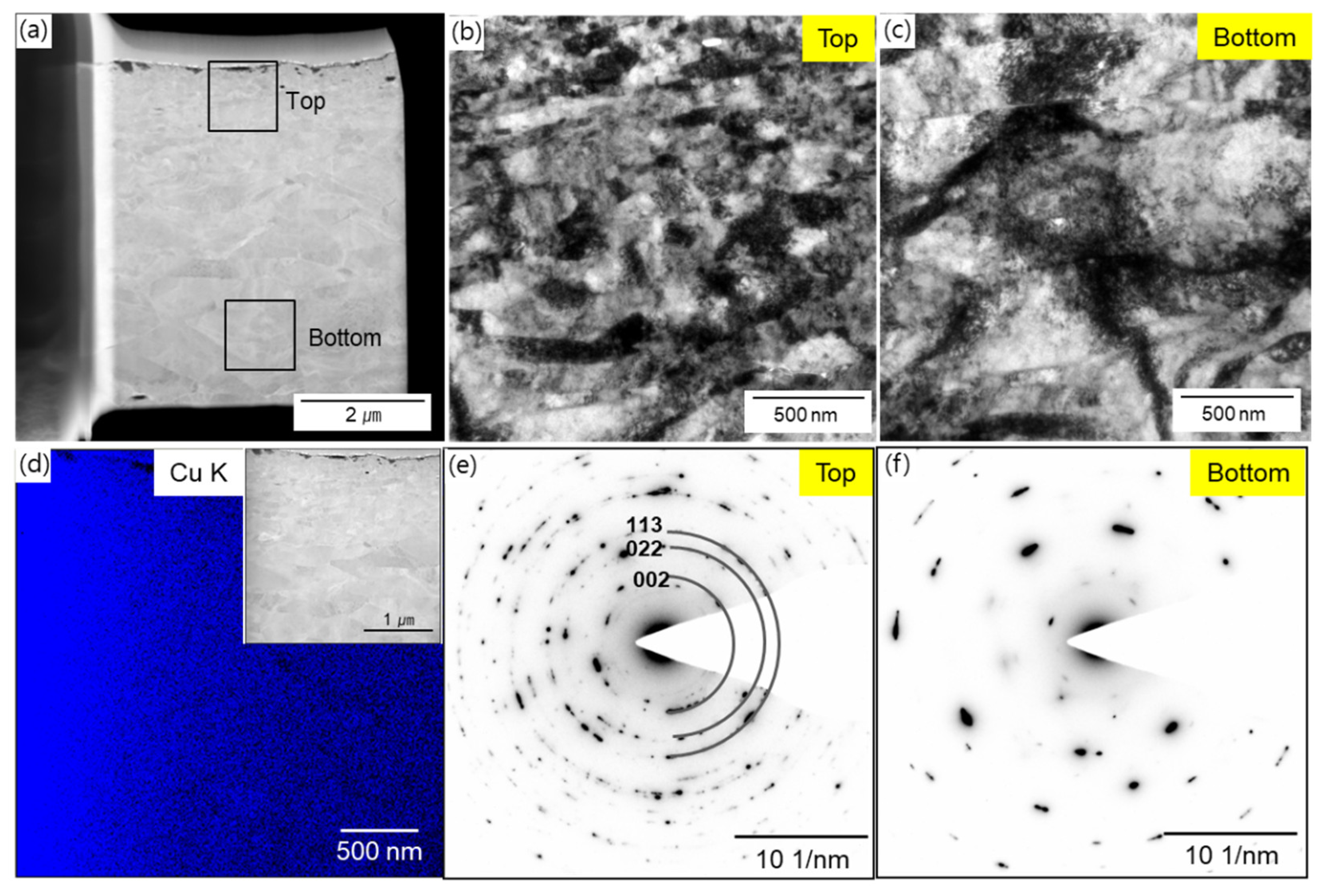
Figure 5 shows the initial TEM microstructural analysis results of the cross-section of the 600-20 sample. To confirm the crystallinity of the Cu matrix, sampling was performed using the FIB, method, as shown in Figure 5a,d. The top and bottom parts were analyzed separately. As can be seen from the TEM images in Figure 5b,c, the grain size decreased from several hundred nanometers (bottom) to several tens of nanometers (top). This is because the surface was subjected to high pressure. In addition, the effect of heat on the inner part of the sample was different from that on the surface. In Figure 5e,f, the selected area diffraction patterns (SADPs) clearly show the differences in the crystallinities of the two regions. Because the smallest grains in the top region were of the order of tens of nanometers in size, its SADP pattern contained a denser ring pattern compared with that for the bottom region (grain size of hundreds of nanometers), further confirming the formation of a gradual grain size distribution during the SPS process.
3.1.2. Density and Mechanical Properties
As shown in Table 1, the relative densities of the samples formed under the different conditions were slightly different. That for the 600-20 sample was 94.36% whereas those for the 800-20 and 800-40 samples were 95.59% and 97.65%, respectively. In all three cases, however, the density was high enough for the samples to be suitable for use as friction materials [34]. In addition, the average hardnesses of the 600-20, 800-20, and 800-40 samples were 101.4, 101.2, and 108.3 HRR, respectively, which were relatively higher than those of the other samples.
3.2. Dry Sliding Wear
3.2.1. Coefficient of Friction (COF)
The COF of each brake pad sample after the completion of the tribological test is shown in Figure 6. The COF rises sharply during the first 2 min until it reaches a value of 0.16–0.29. It then stays constant, exhibiting only small variations, until the end of the test. As shown in Figure 6a–c, for a test load of 3 N, the COF value increases from 0.16 to 0.30 in the following order: 600-20, 800-20, and 800-40. At a load of 5 N, it increased from 0.16 to 0.22, exhibiting a similar trend. Finally, at a load of 10 N, the COF of the 800-40 sample initially fell from 0.21 to 0.17 but then increased gradually as the tribofilm formed, plateauing at approximately 0.22. Thus, the 800-40 sample had a higher COF value and was more stable compared with the other samples. In fact, friction pads are known to be the most stable when they have a COF value of 0.3–0.45 [34,35,36,37]. The COF measurement results can be explained based on the microstructures of the samples, which will be described later.
Figure 6d–f shows that the COF values varied with the load in the case of the samples formed under the same conditions. The trends for the 800-20 and 800-40 samples were similar, and it can be seen that their COF value decreased as the load was increased from 3 N to 10 N. However, in the case of 600-20, the COF value at loads of 3 N and 5 N was approximately 0.16. Nevertheless, it was confirmed that its COF value increased to 0.20 when the load was increased to 10 N. Thus, the SPS conditions have a significant influence on the tribological properties of the brake pads.
3.2.2. Morphology of Worn Surface
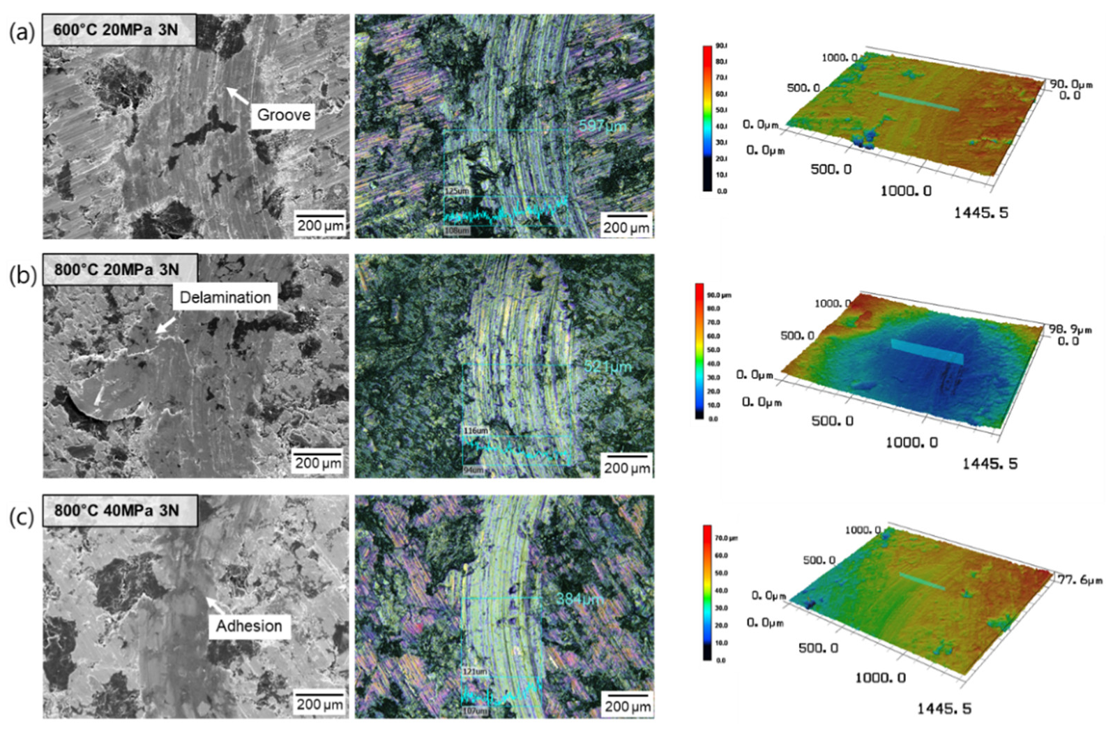
The three-dimensional images obtained using confocal laser microscopy are shown in Figure 7. It can be seen that, in the case of the 600-20 sample, a groove was formed in the wear trace. In addition, the width of the wear trace was approximately 597 μm. In the case of the 800-20 sample, delamination occurred, and the width of the wear trace was approximately 521 μm. Finally, in the case of the 800-40 sample, adhesion was observed on the wear surface, and the wear trace was narrow at approximately 384 μm. Based on the results listed in Table 1, it can be assumed that these observations are attributable to the relative densities and hardnesses of the samples. In particular, it can be seen that the difference in the hardnesses of the brake pads and the steel ball used had a significant effect on the wear characteristics. In addition, the tribological properties were also affected by the SPS conditions.
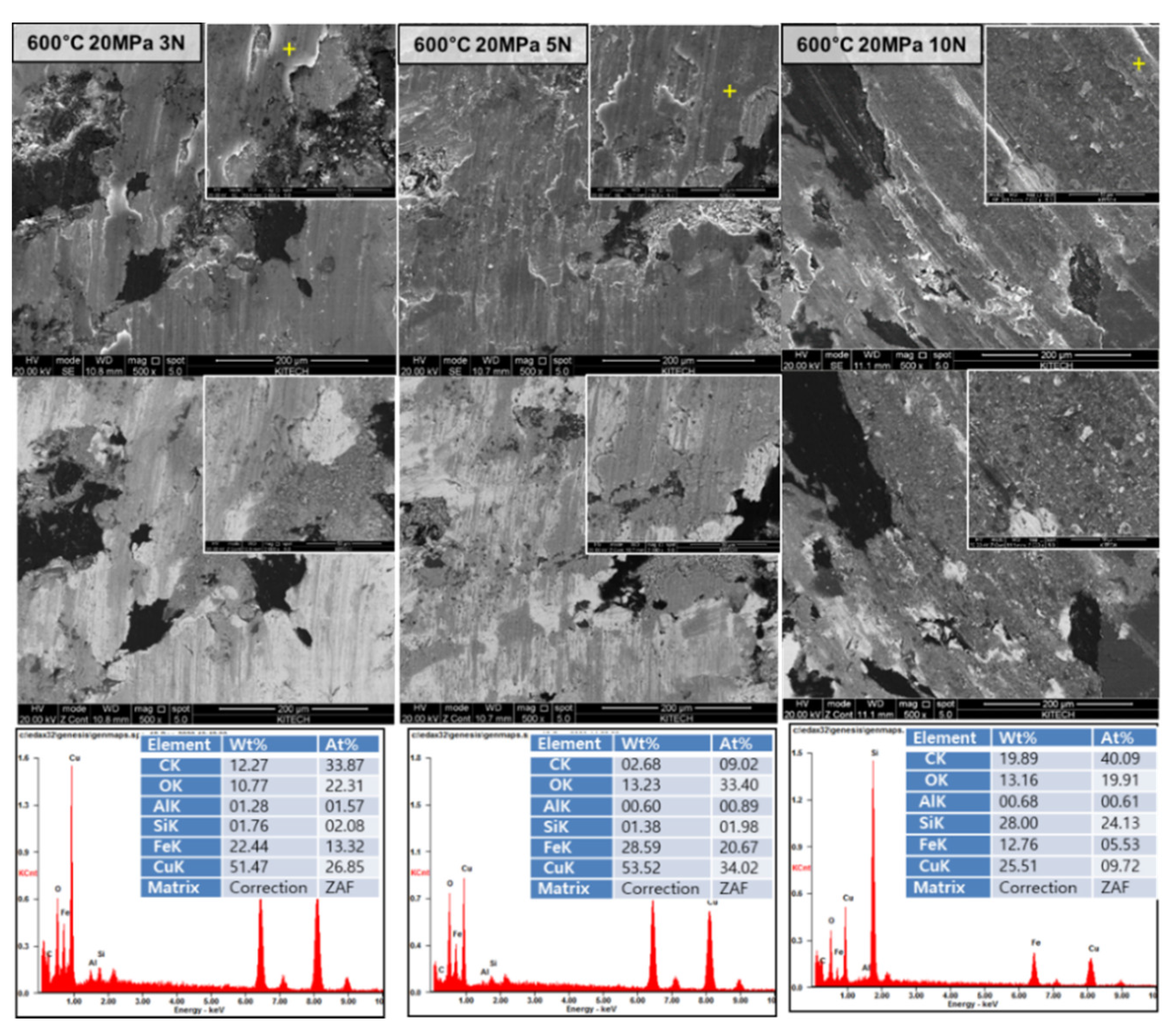
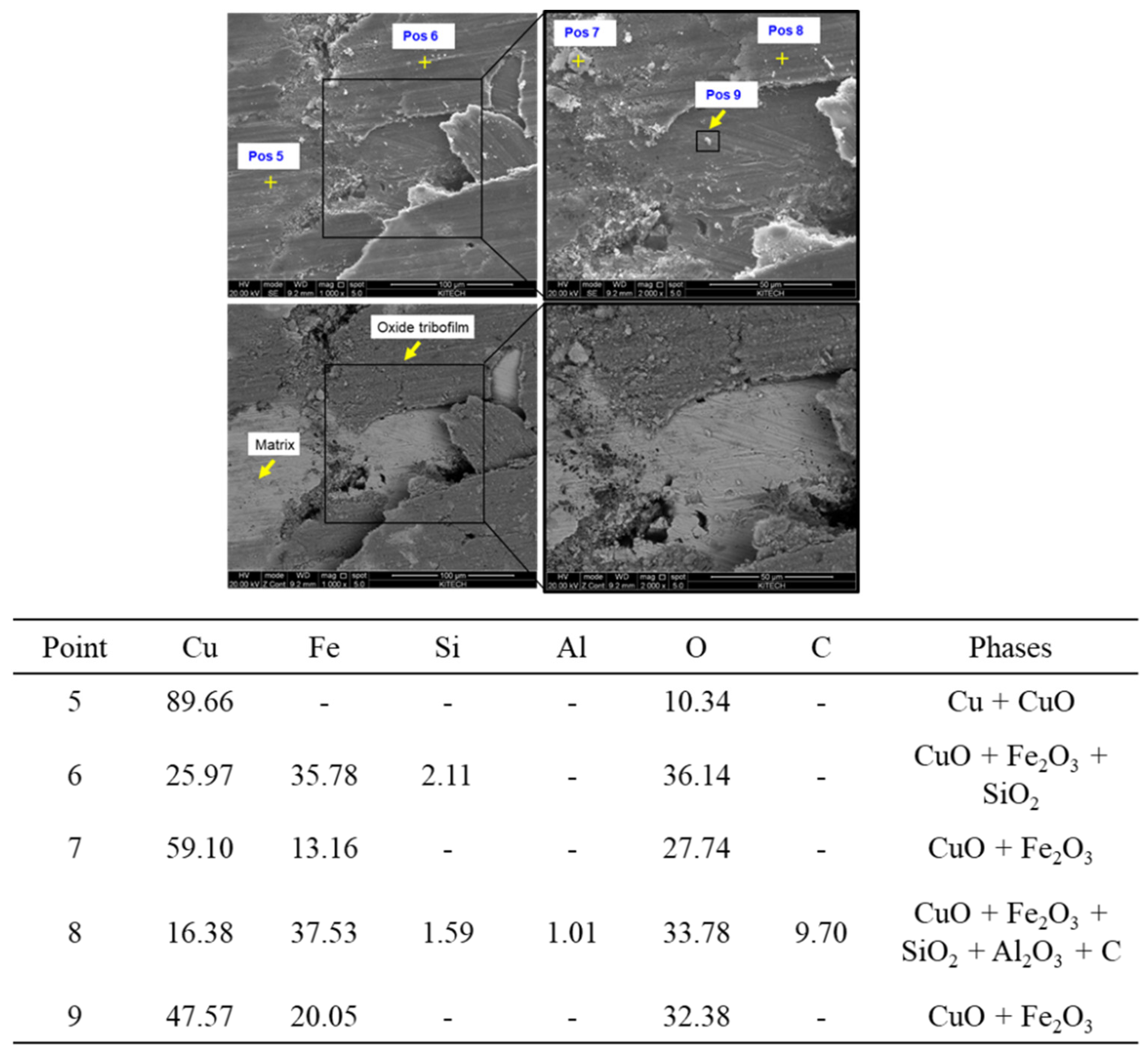
Figure 8 shows secondary electron (SE) and backscatter electron (BSE) images of the 600-20 specimens subjected to different loads. EDS analysis confirmed that oxidation had occurred, with the oxygen content in the 600-20 sample being 10.77–13.23%. Furthermore, as the load was increased, a large amount of debris was generated. Figure 9a,b shows the results of the analysis of the tribofilms formed on the wear traces of the 800-20 and 800-40 samples. It can be seen that an oxide tribofilm formed at both pos1 and pos2 in the case of the 800-20 sample and at pos3 and pos4 in the case of the 800-40 sample. However, in the case of the 800-20 sample, more debris was generated, and the size of the debris was also larger. In general, when the load was large, the amount of debris generated was also large. This is the reason the stable COF value of 800-40 was higher compared with those of the other samples (see Figure 6). The presence of a relatively large amount of debris prevented tribofilm formation in the 600-20 and 800-20 samples, because of which they did not exhibit the desired stable COF values [37,38,39]. To determine what type of debris contributes to stable tribofilm formation, high-magnification SE and BSE images are shown in Figure 10 along with the EDS analysis results for each debris type. The results for pos5 are also shown along with the results of the compositional analysis of the matrix; it can be seen that it was composed of Cu and CuO. The large and small debris particles at pos7 and pos9 were found to consist of CuO and Fe2O3, which were generated by the friction with the steel ball. The debris was pressed and mixed with the matrix to form the tribofilm. The tribofilm at pos6 consisted of CuO, Fe2O3, and SiO2, while that at pos8 consisted of CuO, Fe2O3, SiO2, Al2O3, and C. It is known that the oxide formed by the oxidation of the matrix and that present in the debris must be evenly distributed for the material to exhibit good frictional properties [39,40]. This was confirmed in the present study.
3.2.3. Wear Mechanism
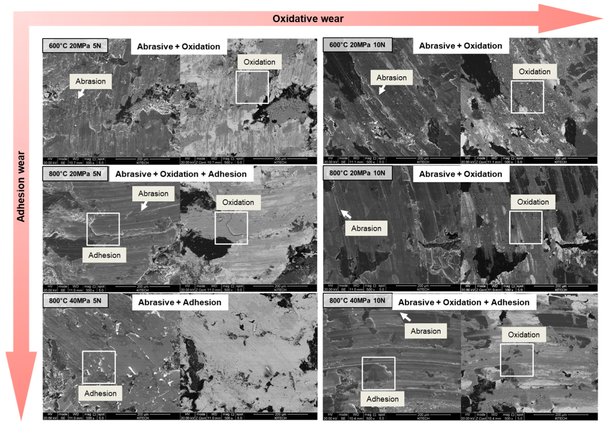
Figure 11 shows SEM and BSE images of the worn surfaces of the different samples. The wear mechanisms of the samples were analyzed based on these images. After the ball-on-disc test at 5 and 10 N, the surfaces of the 600-20, 800-20, and 800-40 samples showed significant wear. For a load of 5 N, the 600-20 sample exhibited abrasion and oxidation. It surface exhibited plowing-damage-related characteristics. In addition, microcutting-related pits and large particles were generated, which caused abrasive wear. In the case of the 800-20 sample, both abrasion and adhesion were observed, which were indicative of slight plowing and Schallamach waves [40]. It is likely that small particles were generated in this sample. Finally, adhesion-related wear was observed in the 800-40 sample, which showed Schallamach wave damage characteristics and barely any debris. Moreover, for a load of 10 N, 600-20 showed abrasive and oxidation wear, and so did 800-20 and 800-40. Finally, as can be seen from the BSE images, the degree of oxidation wear was significantly higher at a load of 10 N than that at a load of 5N.
From these results, it can be concluded that the wear mechanism tends to adhere to adhesion wear as it goes to 600-20, 800-20, and 800-40. This is probably because the hardness and relative density depend on the grain size after sintering. In addition, oxidation-related wear occurs as the load is increased during the tribological test, as more heat is generated at higher loads, resulting in an increase in the oxidation reaction rate. These factors influenced the generation of the tribolayer, thus resulting in the observed differences in the COF.
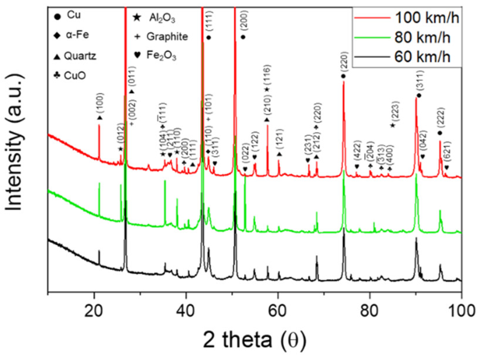
3.2.4. Dynamometer Test
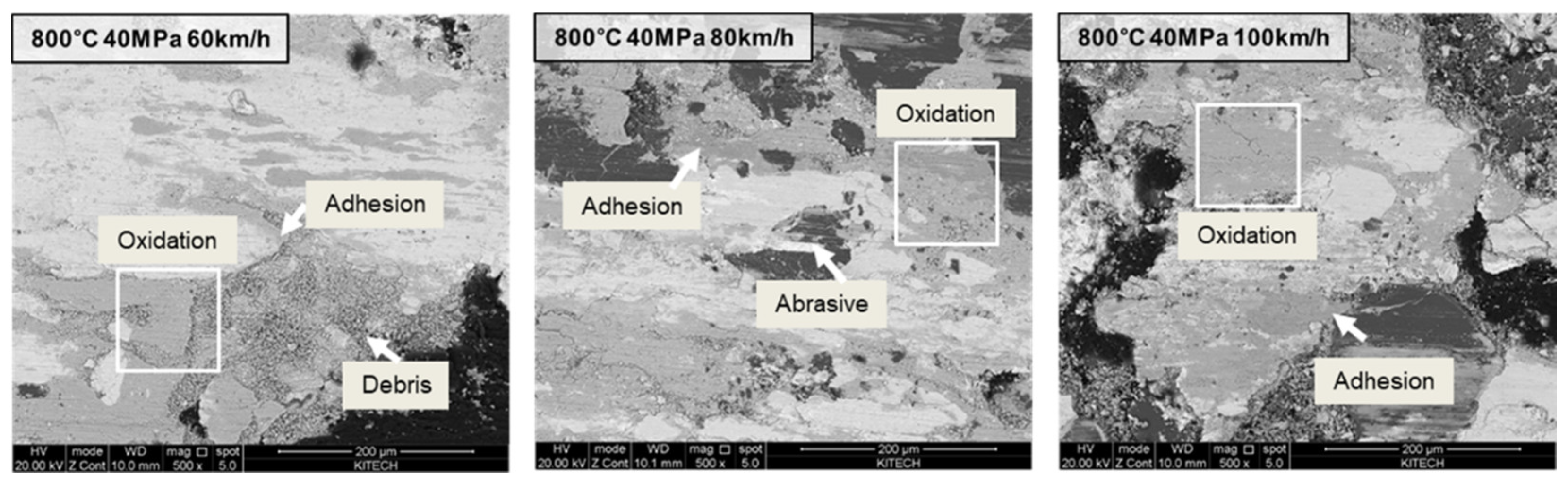
Figure 12 shows the XRD analysis results, that is, the phase compositions, of the various samples after the dynamometer test, which was performed at different wheel running speeds. On comparing these results with those in Figure 4, which shows the XRD analysis results after the ball-on-disc test, it can be confirmed that Fe2O3 and CuO were generated after the dynamometer test. However, the volume fractions of the other phases remained unchanged. Figure 13 shows BSE images of the worn surfaces of the 800-40 specimens after the dynamometer test performed at 60, 80, and 100 km/h. It was confirmed that a greater amount of debris was generated than that after the ball-on-disc test (see Figure 8). However, as was observed after the low-energy ball-on-disc test as well, the high-energy dynamometer test primarily resulted in adhesive wear, and a stable tribofilm was formed. Because a large amount of information is lost at high energy levels, it was difficult to determine the wear mechanism. In addition, it was not possible to determine how the tribofilm was formed and whether debris had accumulated. Thus, the ball-on-disc test was performed for the remaining part of the study. However, in order to verify whether the fabricated friction pads would actually exhibit the same mechanism even under the industrial conditions we planned in this research, we performed the dynamometer test and confirmed that the friction pads exhibited a similar wear mechanism.
4. Conclusions
In this study, we fabricated Cu-based brake pads under different SPS conditions (600 °C–20 MPa, 800 °C–20 MPa, and 800 °C–40 MPa) and subjected them to the ball-on-disc test under various loads (3, 5, and 10 N). Next, we performed surface and cross-sectional analyses of the composite samples in the pristine and post-test states using SEM, TEM, confocal microscopy, and XRD measurements. The following conclusions can be drawn based on the results obtained:
- (1)
- The Cu-based brake pads fabricated under the different SPS conditions showed different relative densities and hardnesses, which varied with the sintering temperature and pressure used. This was owing to the differences in the tribofilm formation mechanism and the COF values during the tribological test. The COF value increased from 0.18 to 0.3 in the following order: 600-20, 800-20, and 800-40.
- (2)
- Based on the sintering temperature and pressure used, the Cu-based brake pads exhibited different wear mechanisms. Sample 600-20 showed abrasive wear while sample 800-20 showed both abrasive and adhesive wear. Finally, sample 800-40 primarily showed adhesive wear. This is because the differences in the hardnesses and relative densities of the samples affected the size and amount of debris produced during the wear test.
- (3)
- During the tribological test, a higher load resulted in a greater degree of oxidation. This is because as a greater load was applied, more heat was generated, accelerating the oxidation process and contributing to the formation of the oxide film. As a result, the samples with high oxidation wear exhibited low COF values.
- (4)
- The dynamometer test was performed on the 800-40 sample, which showed the best friction characteristics in this study. It was confirmed that the dynamometer test resulted in the same wear mechanism as the ball-on-disc test.
- (5)
- The temperature and pressure used during the sintering of brake pads have a determining effect on their friction and wear characteristics. In particular, in the case of the commercial Cu-based brake pads used in aircraft, a temperature and pressure of 800 °C and 40 MPa, respectively, would result in the best wear characteristics. Furthermore, the results of the wear mechanism analysis performed in this study should aid the development of improved Cu-based friction pads.
Author Contributions
Conceptualization, K.I.K. and H.L.; Methodology, K.I.K. and H.L.; Data treatment and validation, K.I.K. and J.K.; Investigation, H.L. and J.K.; Writing—original draft preparation, K.I.K.; Writing—review and editing, K.I.K. and H.L.; Supervision, K.H.O. and K.T.K.; Project administration, K.I.K. and H.L.; Funding acquisition, K.H.O. and K.T.K. All authors have read and agreed to the published version of the manuscript.
Funding
This study was funded by the Korea Agency for Infrastructure Technology Advancement (KAIA; Grant No. 21RSCD-A156406-02) and the Korea Evaluation Institute of Industrial Technology (KEIT) and the Ministry of Trade, Industry and Energy (MOTIE) of the Republic of Korea (No. 1415168877).
Institutional Review Board Statement
Not applicable.
Informed Consent Statement
Not applicable.
Data Availability Statement
The data presented in this study are available on request from the corresponding author. The data are not publicly available due to confidential non-disclosure agreement.
Conflicts of Interest
The authors declare no conflict of interest.
References
- Osterle, W.; Prietzel, C.; Kloss, H.; Dmitriev, A.I. On the role of copper in brake friction materials. Tribol. Int. 2010, 43, 2317–2326. [Google Scholar] [CrossRef]
- Kukutschova, J.; Roubicek, V.; Malachova, K.; Pavlickova, Z.; Holusa, R.; Kubackova, J.; Micka, V.; MacCrimmon, D.; Filip, P. Wear mechanism in automotive brake materials, wear debris and its potential environmental impact. Wear 2009, 267, 807–817. [Google Scholar] [CrossRef] [Green Version]
- Zhou, H.B.; Yao, P.P.; Xiao, Y.L.; Fan, K.Y.; Zhang, Z.Y.; Gong, T.M.; Zhao, L.; Deng, M.W.; Liu, C.; Ling, P. Friction and wear maps of copper metal matrix composites with different iron volume content. Tribol. Int. 2019, 132, 199–210. [Google Scholar] [CrossRef]
- Cheng, J.B.; Liang, X.B.; Xu, B.S. Devitrification of arc-sprayed FeBSiNb amorphous coatings: Effects on wear resistance and mechanical behavior. Surf. Coat. Technol. 2013, 235, 720–726. [Google Scholar] [CrossRef]
- Hong, S.; Lin, J.; Wu, Y.; Wu, J.; Zheng, Y.; Zhang, Y.; Cheng, J.; Sun, W. Cavitation erosion characteristics at various flow velocities in NaCl medium of carbide-based cermet coatings prepared by HVOF spraying. Ceram. Int. 2021, 47, 1929–1939. [Google Scholar] [CrossRef]
- Shaik, M.A.; Golla, B.R. Densification, microstructure and properties of mechanically alloyed and hot-pressed Cu-15 wt% Al alloy. J. Mater. Sci. 2018, 53, 14694–14712. [Google Scholar] [CrossRef]
- Wang, Y.; Wang, Q.J. Lubrication regimes. In Encyclopedia of Tribology; Wang, Q.J., Chung, Y.-W., Eds.; Springer: New York, NY, USA, 2013; pp. 2110–2113. ISBN 978-0-387-92898-2. [Google Scholar]
- Zhang, P.; Zhang, L.; Wei, D.B.; Wu, P.F.; Cao, J.W.; Shijia, C.R.; Qu, X.H. A high-performance copper-based brake pad for high-speed railway trains and its surface substance evolution and wear mechanism at high temperature. Wear 2020, 444, 203182. [Google Scholar] [CrossRef]
- Sun, Q.C.; Wang, Z.X.; Yin, B.; Yang, J.; Liu, J.J.; Liu, Y.L.; Cheng, J.; Zhu, S.Y.; Qiao, Z.H. The tribological properties and wear mechanism of copper coated graphite doped Sialon ceramic composites at wide range temperature from 25 to 800 °C. Tribol. Int. 2018, 123, 10–16. [Google Scholar] [CrossRef]
- Zhang, P.; Zhang, L.; Fu, K.; Cao, J.; Shijia, C.; Qu, X. Effects of different forms of Fe powder additives on the simulated braking performance of Cu-based friction materials for high-speed railway trains. Wear 2018, 414, 317–326. [Google Scholar] [CrossRef]
- Xiong, X.; Chen, J.; Yao, P.; Li, S.; Huang, B. Friction and wear behaviors and mechanisms of Fe and SiO2 in Cu-based P/M friction materials. Wear 2007, 262, 1182–1186. [Google Scholar] [CrossRef]
- Sun, W.; Zhou, W.; Liu, J.; Fu, X.; Chen, G.; Yao, S. The Size Effect of SiO2 Particles on Friction Mechanisms of a Composite Friction Material. Tribol. Lett. 2018, 66, 35. [Google Scholar] [CrossRef]
- Peng, T.; Yan, Q.; Li, G.; Zhang, X. The Influence of Cu/Fe Ratio on the Tribological Behavior of Brake Friction Materials. Tribol. Lett. 2018, 66, 18. [Google Scholar] [CrossRef]
- Zhang, P.; Zhang, L.; Fu, K.; Wu, P.; Cao, J.; Shijia, C.; Qu, X. The effect of Al2O3 fiber additive on braking performance of copper-based brake pads utilized in high-speed railway train. Tribol. Int. 2019, 135, 444–456. [Google Scholar] [CrossRef]
- Chen, B.; Bi, Q.; Yang, J.; Xia, Y.; Hao, J. Tribological properties of solid lubricants (graphite, h-BN) for Cu-based P/M friction composites. Tribol. Int. 2008, 41, 1145–1152. [Google Scholar] [CrossRef]
- Kovalchenko, A.M.; Fushchich, O.I.; Danyluk, S. The tribological properties and mechanism of wear of Cu-based sintered powder materials containing molybdenum disulfide and molybdenum diselenite under unlubricated sliding against copper. Wear 2012, 290, 106–123. [Google Scholar] [CrossRef]
- Senouci, A.; Frene, J.; Zaidi, H. Wear mechanism in graphite-copper electrical sliding contact. Wear 1999, 225, 949–953. [Google Scholar] [CrossRef]
- Xiao, Y.; Yao, P.; Zhou, H.; Zhang, Z.; Gong, T.; Zhao, L.; Deng, M. Investigation on Speed-Load Sensitivity to Tribological Properties of Copper Metal Matrix Composites for Braking Application. Metals 2020, 10, 889. [Google Scholar] [CrossRef]
- Xiao, Y.; Zhang, Z.; Yao, P.; Fan, K.; Zhou, H.; Gong, T.; Zhao, L.; Deng, M. Mechanical and tribological behaviors of copper metal matrix composites for brake pads used in high-speed trains. Tribol. Int. 2018, 119, 585–592. [Google Scholar] [CrossRef]
- Peng, T.; Yan, Q.; Zhang, X. Stability of Metal Matrix Composite Pads During High-Speed Braking. Tribol. Lett. 2018, 66. [Google Scholar] [CrossRef]
- Xiao, J.-K.; Xiao, S.-X.; Chen, J.; Zhang, C. Wear mechanism of Cu-based brake pad for high-speed train braking at speed of 380 km/h. Tribol. Int. 2020, 150, 106357. [Google Scholar] [CrossRef]
- Zhang, P.; Zhang, L.; Wei, D.; Wu, P.; Cao, J.; Shijia, C.; Qu, X. Adjusting function of MoS2 on the high-speed emergency braking properties of copper-based brake pad and the analysis of relevant tribo-film of eddy structure. Compos. Part B Eng. 2020, 185, 107779. [Google Scholar] [CrossRef]
- Zhang, P.; Zhang, L.; Wu, P.; Cao, J.; Shijia, C.; Wei, D.; Qu, X. Effect of carbon fiber on the braking performance of copper-based brake pad under continuous high-energy braking conditions. Wear 2020, 458, 203408. [Google Scholar] [CrossRef]
- Akhtar, F.; Askari, S.J.; Shah, K.A.; Du, X.L.; Guo, S.J. Microstructure, mechanical properties, electrical conductivity and wear behavior of high volume TiC reinforced Cu-matrix composites. Mater. Charact. 2009, 60, 327–336. [Google Scholar] [CrossRef]
- Gupta, P.; Kumar, D.; Parkash, O.; Jha, A.K.; Sadasivuni, K.K. Dependence of wear behavior on sintering mechanism for Iron-Alumina Metal Matrix Nanocomposites. Mater. Chem. Phys. 2018, 220, 441–448. [Google Scholar] [CrossRef]
- Zhan, Y.Z.; Zhang, G.D. Friction and wear behavior of copper matrix composites reinforced with SiC and graphite particles. Tribol. Lett. 2004, 17, 91–98. [Google Scholar] [CrossRef]
- Dudina, D.V.; Bokhonov, B.B. Elimination of oxide films during Spark Plasma Sintering of metallic powders: A case study using partially oxidized nickel. Adv. Powder Technol. 2017, 28, 641–647. [Google Scholar] [CrossRef]
- Jayashree, P.; Menapace, C.; Turani, S.; Straffelini, G. Dry sliding behaviour of composite friction materials with varying iron and copper content prepared using the spark plasma sintering technique. Powder Metall. 2021, 1–13. [Google Scholar] [CrossRef]
- Ayyappadas, C.; Muthuchamy, A.; Raja Annamalai, A.; Agrawal, D.K. An investigation on the effect of sintering mode on various properties of copper-graphene metal matrix composite. Adv. Powder Technol. 2017, 28, 1760–1768. [Google Scholar] [CrossRef]
- Dash, K.; Ray, B.C.; Chaira, D. Synthesis and characterization of copper–alumina metal matrix composite by conventional and spark plasma sintering. J. Alloys Compd. 2012, 516, 78–84. [Google Scholar] [CrossRef]
- Ikeuchi, K.; Handa, K.; Lunden, R.; Vernersson, T. Wheel tread profile evolution for combined block braking and wheel-rail contact: Results from dynamometer experiments. Wear 2016, 366, 310–315. [Google Scholar] [CrossRef]
- Efe, G.C.; Yener, T.; Altinsoy, I.; Ipek, M.; Zeytin, S.; Bindal, C. The effect of sintering temperature on some properties of Cu-SiC composite. J. Alloys Compd. 2011, 509, 6036–6042. [Google Scholar] [CrossRef]
- Wang, X.J.; Yao, X.M.; Zhang, H.; Liu, X.J.; Huang, Z.R. Tribological properties and wear mechanisms of hot-pressed sintering mesocarbon microbeads (MCMBs)-SiC composites against different counterparts. Ceram. Int. 2020, 46, 3896–3903. [Google Scholar] [CrossRef]
- Liew, K.W.; Nirmal, U. Frictional performance evaluation of newly designed brake pad materials. Mater. Des. 2013, 48, 25–33. [Google Scholar] [CrossRef]
- Uyyuru, R.K.; Surappa, M.K.; Brusethaug, S. Tribological behavior of Al-Si-SiCp composites/automobile brake pad system under dry sliding conditions. Tribol. Int. 2007, 40, 365–373. [Google Scholar] [CrossRef]
- Rodrigues, A.C.P.; Österle, W.; Gradt, T.; Azevedo, C.R.F. Impact of copper nanoparticles on tribofilm formation determined by pin-on-disc tests with powder supply: Addition of artificial third body consisting of Fe3O4, Cu and graphite. Tribol. Int. 2017, 110, 103–112. [Google Scholar] [CrossRef]
- Ma, C.; Wang, S.C.; Wang, L.P.; Walsh, F.C.; Wood, R.J.K. The role of a tribofilm and wear debris in the tribological behaviour of nanocrystalline Ni-Co electrodeposits. Wear 2013, 306, 296–303. [Google Scholar] [CrossRef]
- Biswas, S.K. Some mechanisms of tribofilm formation in metal/metal and ceramic/metal sliding interactions. Wear 2000, 245, 178–189. [Google Scholar] [CrossRef]
- Nan, F.; Xu, Y.; Xu, B.S.; Gao, F.; Wu, Y.X.; Tang, X.H. Effect of natural attapulgite powders as lubrication additive on the friction and wear performance of a steel tribo-pair. Appl. Surf. Sci. 2014, 307, 86–91. [Google Scholar] [CrossRef]
- Berger, H.R.; Heinrich, G. Friction effects in the contact area of sliding rubber: A generalized Schallamach model. Kautsch. Gummi Kunstst. 2000, 53, 200–205. [Google Scholar]
Figure 1.
Backscatter electron (BSE) image and energy-dispersive X-ray spectroscopy (EDS) analysis results of surfaces and cross-sections of Cu-based 600-20 brake pad.
Figure 1.
Backscatter electron (BSE) image and energy-dispersive X-ray spectroscopy (EDS) analysis results of surfaces and cross-sections of Cu-based 600-20 brake pad.

Figure 2.
Scanning electron microscopy (SEM) images of surface microstructures of 600-20, 800-20, and 800-40 samples.
Figure 2.
Scanning electron microscopy (SEM) images of surface microstructures of 600-20, 800-20, and 800-40 samples.

Figure 3.
SEM images of cross-sectional microstructure of 600-20, 800-20, and 800-40 samples.

Figure 4.
X-ray diffraction (XRD) spectra of surfaces of Cu-based brake pads fabricated under different conditions.
Figure 4.
X-ray diffraction (XRD) spectra of surfaces of Cu-based brake pads fabricated under different conditions.

Figure 5.
Transmission electron microscopy (TEM) images of Cu-based brake pads: (a) cross-section view of 600-20 sample and (b,c) TEM images of top and bottom regions of sample in (a). (d) EDS results for cross-section of sample in (a) and (e,f) SADP analysis results of top and bottom regions of sample in (a).

Figure 6.
Variations in coefficient of friction (COF) of Cu-based brake pads under different loads: (a) 3, (b) 5, and (c) 10 N. Variations in COF of (d) 600-20, (e) 800-20, and (f) 800-40 samples during ball-on-disc test conducted for 1000 s.
Figure 6.
Variations in coefficient of friction (COF) of Cu-based brake pads under different loads: (a) 3, (b) 5, and (c) 10 N. Variations in COF of (d) 600-20, (e) 800-20, and (f) 800-40 samples during ball-on-disc test conducted for 1000 s.

Figure 7.
BSE images (left), confocal images (center), and 3D images (right) of worn surfaces of (a) 600-20, (b) 800-20, (c) 800-40 samples.
Figure 7.
BSE images (left), confocal images (center), and 3D images (right) of worn surfaces of (a) 600-20, (b) 800-20, (c) 800-40 samples.

Figure 8.
SEM and BSE images and EDS analysis results of 600-20 sample after being evaluated at 3, 5, and 10 N.
Figure 8.
SEM and BSE images and EDS analysis results of 600-20 sample after being evaluated at 3, 5, and 10 N.

Figure 9.
SEM and BSE images and EDS analysis results of worn surfaces of (a) 800-20 and (b) 800-40 samples after ball-on-disc test performed at 3 and 10 N.
Figure 9.
SEM and BSE images and EDS analysis results of worn surfaces of (a) 800-20 and (b) 800-40 samples after ball-on-disc test performed at 3 and 10 N.

Figure 10.
Characterization of debris formed using high-magnification BSE imaging and EDS analysis results for various positions in BSE images.
Figure 10.
Characterization of debris formed using high-magnification BSE imaging and EDS analysis results for various positions in BSE images.

Figure 11.
Wear mechanism of samples formed under different SPS conditions.

Figure 12.
XRD spectra of surfaces of Cu-based brake pads after dynamometer test performed at different wheel running speeds.
Figure 12.
XRD spectra of surfaces of Cu-based brake pads after dynamometer test performed at different wheel running speeds.

Figure 13.
BSE images of worn surface of Cu-based brake pad after dynamometer test performed at speeds of 60, 80, and 100 km/h.
Figure 13.
BSE images of worn surface of Cu-based brake pad after dynamometer test performed at speeds of 60, 80, and 100 km/h.


Table 1.
Spark plasma sintering (SPS) conditions used in this study and relative densities and hardnesses of samples formed under different SPS conditions.
Table 1.
Spark plasma sintering (SPS) conditions used in this study and relative densities and hardnesses of samples formed under different SPS conditions.
| Number | Processing Condition | Relative Density (%) | Hardness (HRR) | |||
|---|---|---|---|---|---|---|
| Heating Rate (°C/min) | Sintering Temp. (°C) | Pressure (MPa) | Time (min) | |||
| 1 | 50 | 800 | 20 | 10 | 95.59 | 101.2 |
| 2 | 40 | 97.65 | 108.3 | |||
| 3 | 700 | 20 | 20 | 95.59 | 102.5 | |
| 4 | 600 | 10 | 20 | 82.20 | 61.6 | |
| 5 | 20 | 10 | 94.36 | 101.4 | ||
| 6 | 20 | 92.71 | 98.2 | |||
| 7 | 400 | 20 | 10 | 83.44 | 89.8 | |
| 8 | 40 | 89.41 | 105.5 | |||
Publisher’s Note: MDPI stays neutral with regard to jurisdictional claims in published maps and institutional affiliations. |
© 2021 by the authors. Licensee MDPI, Basel, Switzerland. This article is an open access article distributed under the terms and conditions of the Creative Commons Attribution (CC BY) license (https://creativecommons.org/licenses/by/4.0/).
Share and Cite
MDPI and ACS Style
Kim, K.I.; Lee, H.; Kim, J.; Oh, K.H.; Kim, K.T. Wear Behavior of Commercial Copper-Based Aircraft Brake Pads Fabricated under Different SPS Conditions. Crystals 2021, 11, 1298. https://0-doi-org.brum.beds.ac.uk/10.3390/cryst11111298
AMA Style
Kim KI, Lee H, Kim J, Oh KH, Kim KT. Wear Behavior of Commercial Copper-Based Aircraft Brake Pads Fabricated under Different SPS Conditions. Crystals. 2021; 11(11):1298. https://0-doi-org.brum.beds.ac.uk/10.3390/cryst11111298
Chicago/Turabian StyleKim, Kyung Il, Hyunjong Lee, Jongbeom Kim, Kyu Hwan Oh, and Kyung Taek Kim. 2021. "Wear Behavior of Commercial Copper-Based Aircraft Brake Pads Fabricated under Different SPS Conditions" Crystals 11, no. 11: 1298. https://0-doi-org.brum.beds.ac.uk/10.3390/cryst11111298
Note that from the first issue of 2016, this journal uses article numbers instead of page numbers. See further details here.