
Strain Rate and Temperature Effects on Tensile Properties of Polycrystalline Cu6Sn5 by Molecular Dynamic Simulation

1
Engineering Research Center of Electronic Information Materials and Devices, Ministry of Education, Guilin University of Electronic Technology, Guilin 541004, China
2
School of Mechanical and Electrical Engineering, Guilin University of Electronic Technology, Guilin 541004, China
*
Author to whom correspondence should be addressed.
Crystals 2021, 11(11), 1415; https://0-doi-org.brum.beds.ac.uk/10.3390/cryst11111415
Submission received: 26 October 2021
/
Revised: 12 November 2021
/
Accepted: 17 November 2021
/
Published: 19 November 2021
(This article belongs to the Special Issue Crystal Plasticity (Volume II))
Abstract
:Intermetallic compounds (IMCs) are essential in the soldering of electronic products and are composed mainly of Cu6Sn5 and Cu3Sn. They must maintain reliable mechanical and electrical connections. As they are usually only a few microns thick, and it is difficult to study their mechanical properties by traditional methods. In this study, a 100 Å × 100 Å × 100 Å polycrystal with 10 grains was created by Atomsk through Voronoi tessellation based on a Cu6Sn5 unit cell. The effects of the temperature and strain rate on the tensile properties of the polycrystalline Cu6Sn5 were analyzed based on MEAM potential function using a molecular dynamics (MD) method. The results show that Young’s modulus and ultimate tensile strength (UTS) of the polycrystalline Cu6Sn5 decrease approximately linearly with an increase in temperature. At high strain rates (0.001–100 ps−1), Young’s modulus and UTS of the Cu6Sn5 are logarithmic with respect to the strain rate, and both increase with an increase in strain rate. In addition, at low strain rates (0.00001–0.0005 ps−1), the UTS has a quadratic increase as the strain rate increases.
1. Introduction
With the integration and miniaturization of electronic products, electronic packaging and assembly technologies are progressing toward achieving high density and small size. Therefore, the size of solder joints has dropped sharply from hundreds of microns to tens of microns, or even a few microns [1]. Intermetallic compounds (IMCs) are formed between the solder joint and pad during soldering because of interfacial reactions. At present, the most commonly used solders in electronic products are the Sn–Ag–Cu (SAC) and Sn–Cu (SC) lead-free solders [2,3], and the primary composites of IMCs are Cu6Sn5 and Cu3Sn [3]. IMCs are a prerequisite for reliable connection for electronic products [4]. Therefore, the mechanical properties of IMCs significantly affect those of the entire solder joints [3].
As the thickness of the IMC is only a few microns, it is difficult to obtain its mechanical properties using conventional methods. There are usually two methods to study the mechanical properties of IMC: experiments and simulation. In the experimental method, specific samples are usually required, and nanoindentations are adopted to test the hardness and Young’s modulus of the IMC [5,6,7,8,9,10,11]. However, the results tested by nanoindentation fluctuate within a certain range because it is difficult to obtain a pure IMC to ensure the consistency of samples. In the simulation method, first-principles and MD methods are usually used. First-principles based on quantum mechanics can be used to obtain relatively accurate physical parameters of a material [12,13]. However, the first-principles method requires massive computing resources; therefore, only a system with just a few atoms can be calculated. Molecular dynamics (MDs) based on classical mechanic theories can ease this problem. With the development of computer technology, MD simulation can be used to simulate atomic systems at the micro and nanoscales. IMC properties such as thermodynamic, mechanical, and diffusion properties can be obtained by MD simulation [14,15,16,17,18,19]. The crystal size and strain rate can influence the tensile properties of a single crystal Ni3Sn4 via MD simulation [16,19]. Studies have shown that the strain rate affects the tensile properties of the materials, and the UTS of the material increases with the increase in the strain rate [20,21,22,23,24,25]. The results of previous studies were primarily based on experiments. However, because the thickness of IMCs is only a few microns, it is difficult to study their tensile properties by traditional experimental methods.
The previous studies on the mechanical properties of diffusion properties of IMCs were all based on monocrystals. However, most of the IMCs in solder joints are polycrystals, and their mechanical properties differ from those of monocrystals. In this study, the mechanical properties of a polycrystalline Cu6Sn5 were studied using the MD method, considering the effects of strain rate and temperature on the tensile properties. The temperature range in this study is within 250 to 500 K (melting point of Cu6Sn5 is 688 K [5]), and the strain rate is 0.00001 to 100 ps−1. In this study, the strain rate exceeding 0.001 ps−1 represents a high strain rate, and from 0.00001 to 0.001 ps−1 represents a low strain rate. The tensile properties in both situations are discussed separately in Section 3.
2. Methodology
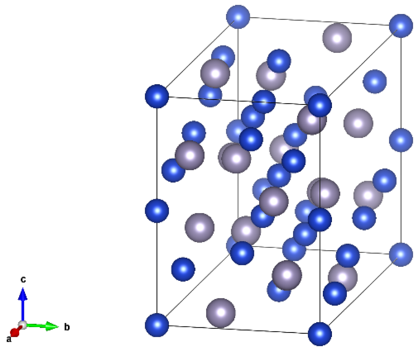
2.1. Structure of Cu6Sn5 Unit Cell
2.2. Modified Embedded Atom Method (MEAM) Potential
In the MEAM theory, the total energy of the system consists of two parts: the energy embedding an atom in the background electron density and a pair interaction, which is described by Equations (1) and (2) [27,29].
where Fi is the embedding energy of the atom i, Φij is the interaction potential between atoms i and j, and Rij is the distance between atoms i and j. The parameters in the MEAM potential and their implications can be obtained from the literature [27,29]. For pure metals, the parameters in the MEAM potential function mainly include the cohesive energy Ec, equilibrium nearest-neighbor distance r0, exponential decay factor for the universal energy function α, scaling factor for the embedding energy, the exponential decay factors for the atomic densities β (i, i = 0, 1, 2, 3), the weighting factors for the atomic densities t (i, i = 1, 2, 3), and the density scaling parameter ρ. For alloys, in addition to the above parameters, interaction parameters between the two pure metals could also be included, such as the binding energy between two different metal atoms, equilibrium nearest-neighbor distance between two types of atoms, and exponential decay factor for the universal energy function of the two atoms. Table 1 list the primary parameters in the potential according to references [29]. There is a many-body screening function in the MEAM, and the screening parameter C is adopted to determine the screening extent. Cmin and Cmax represent the minimum and maximum values of the screening boundaries, respectively [29]. Values of the Cmin and Cmax in this study are shown in Table 2 according to reference [29].
3. Results and Discussion
3.1. Details of the MD Simulation
3.1.1. Monocrystalline and Polycrystalline Structures of Cu6Sn5
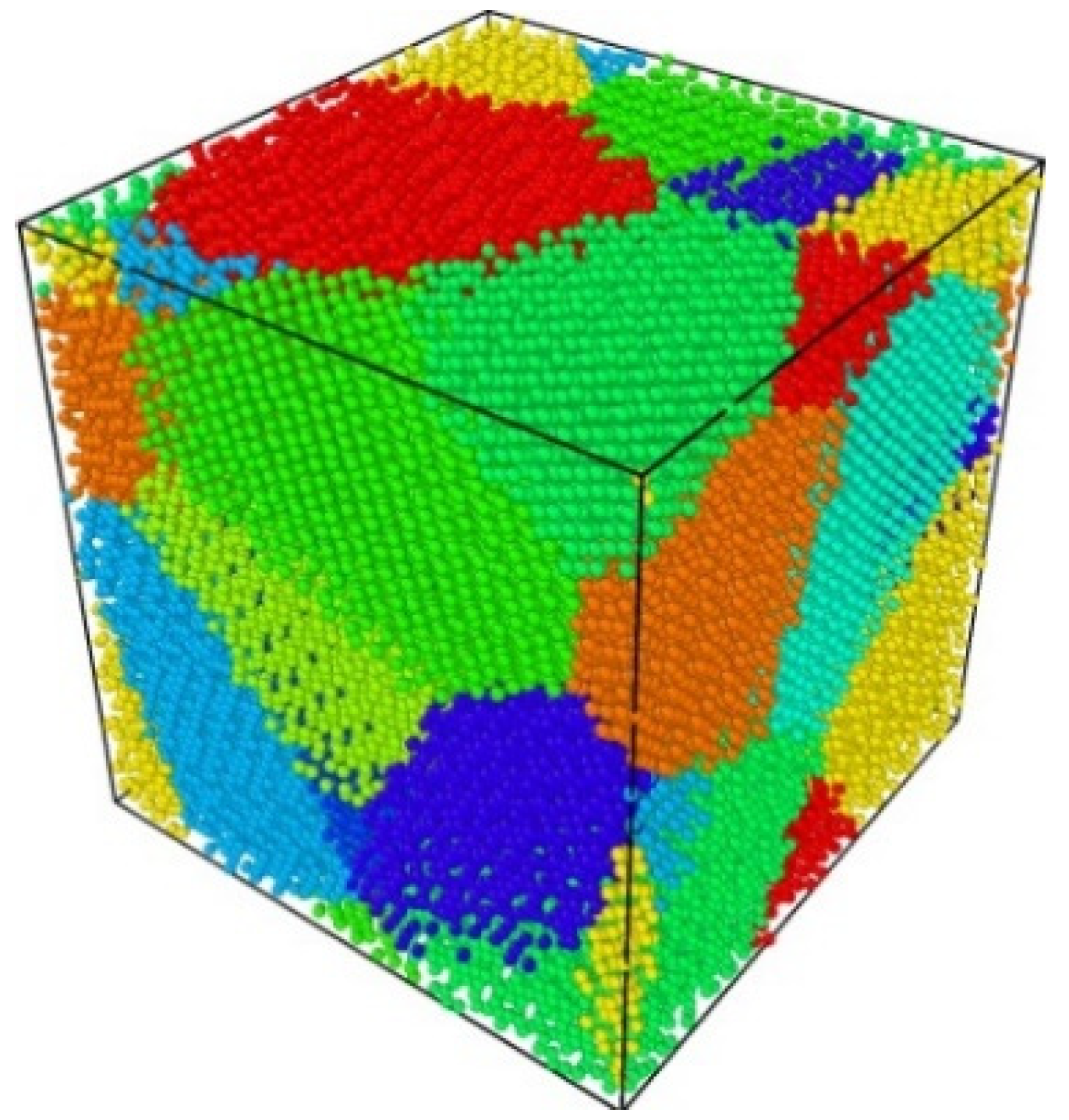
Based on a Cu6Sn5 unit cell, polycrystalline Cu6Sn5 can be created by Atomsk through Voronoi tessellation [30]. The box size and number of the grain seeds can be determined when creating polycrystals. For example, a 100 Å × 100 Å × 100 Å polycrystal with 10 grains is shown in Figure 2. Different colors represent different grain identifications (IDs).
3.1.2. Validation of the MEAM Potential
Table 3 lists the stiffness constants calculated via the large-scale atomic/molecular massively parallel simulator (LAMMPS) with the MEAM potential in our study and by the first-principles method in reference [31]. Table 4 lists the elastic moduli of polycrystals, including bulk modulus (B), shear modulus (G), and Young’s modulus (E), obtained via the Voigt–Reuss–Hill (VRH) methods. Though some of the stiffness constants obtained from both methods differ, the value of the elastic moduli of the polycrystalline Cu6Sn5 is within the calculated result by Ghosh [32] and Lee [31]. Our MD simulations were performed based on this MEAM potential.
3.1.3. Simulation Setting
By using the proposed MD simulation, the stress–strain relations of the polycrystals were studied by stretching the polycrystals at different temperatures and strain rates. The polycrystal was fully relaxed under NVE, NVT, and NPT ensembles alternately to make the system reach target setting temperatures and pressures and was stretched under the NPT ensemble. To access the effects of the strain rate, the polycrystals were stretched at stain rates of 0.00001 to 100 ps−1. In addition, the temperature effect over a temperature range of 250–500 K with intervals of 50 K was considered in our study.
3.2. Isotropic Analysis of Tensile Properties of Polycrystals
To determine the isotropic characteristics of the polycrystalline Cu6Sn5, it was stretched along the x-, y-, and z-axis, respectively, at 300 K with a strain rate of 1 ps−1. Figure 3 shows the stress–strain response. Stress_x, Stress_y, and Stress_z represent stretching along the x-, y-, and z-axis, respectively. The three curves almost overlapped before the polycrystalline Cu6Sn5 cracked, specifically in the linear elastic deformation phase. This indicates that the tensile properties of the polycrystalline Cu6Sn5 along the x, y, and z directions are very similar to each other. Therefore, the polycrystalline Cu6Sn5 in our study is isotropic, which is consistent with the real polycrystal materials [33].
3.3. Temperature Effect on Tensile Properties of Polycrystalline Cu6Sn5
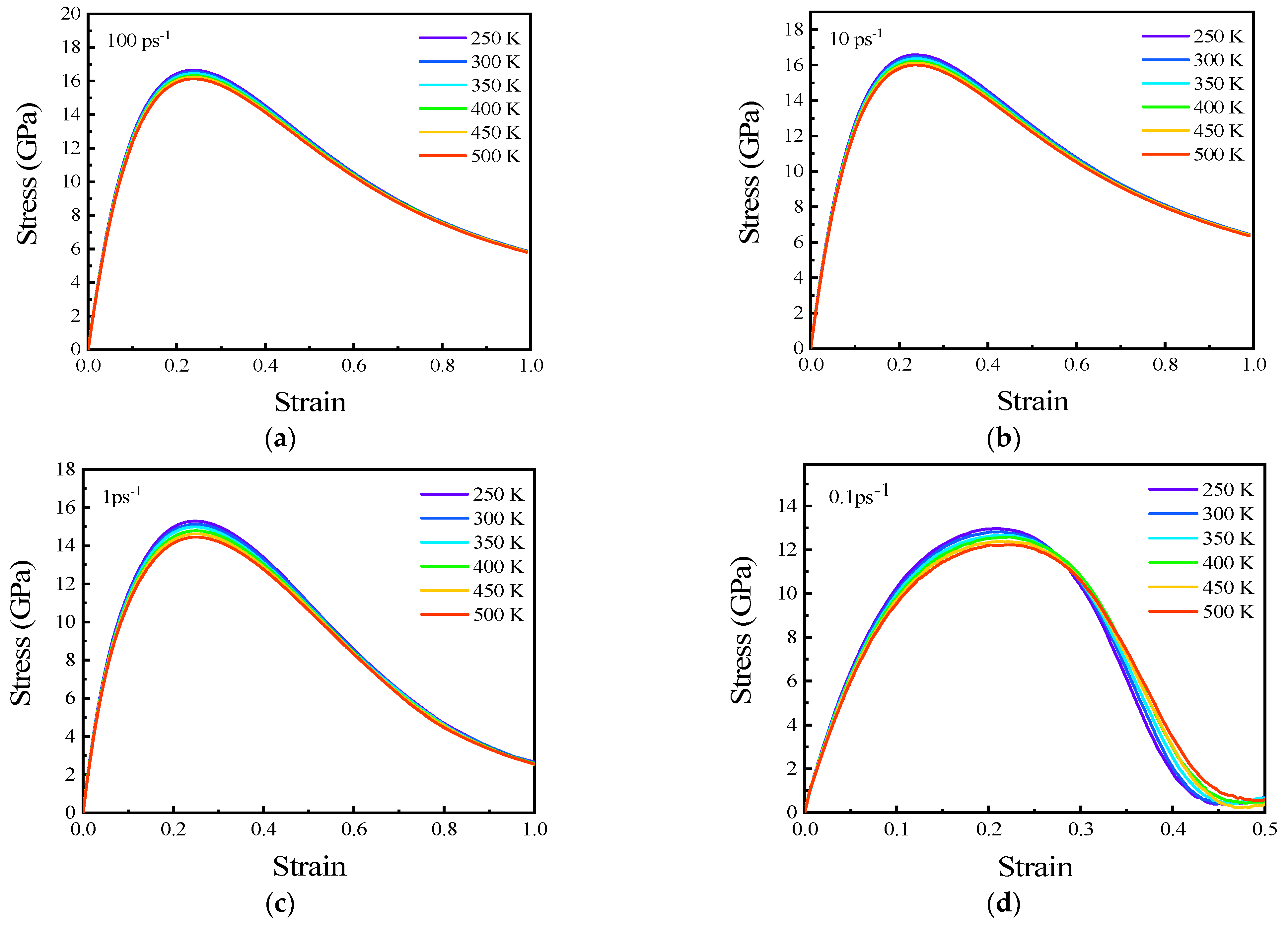
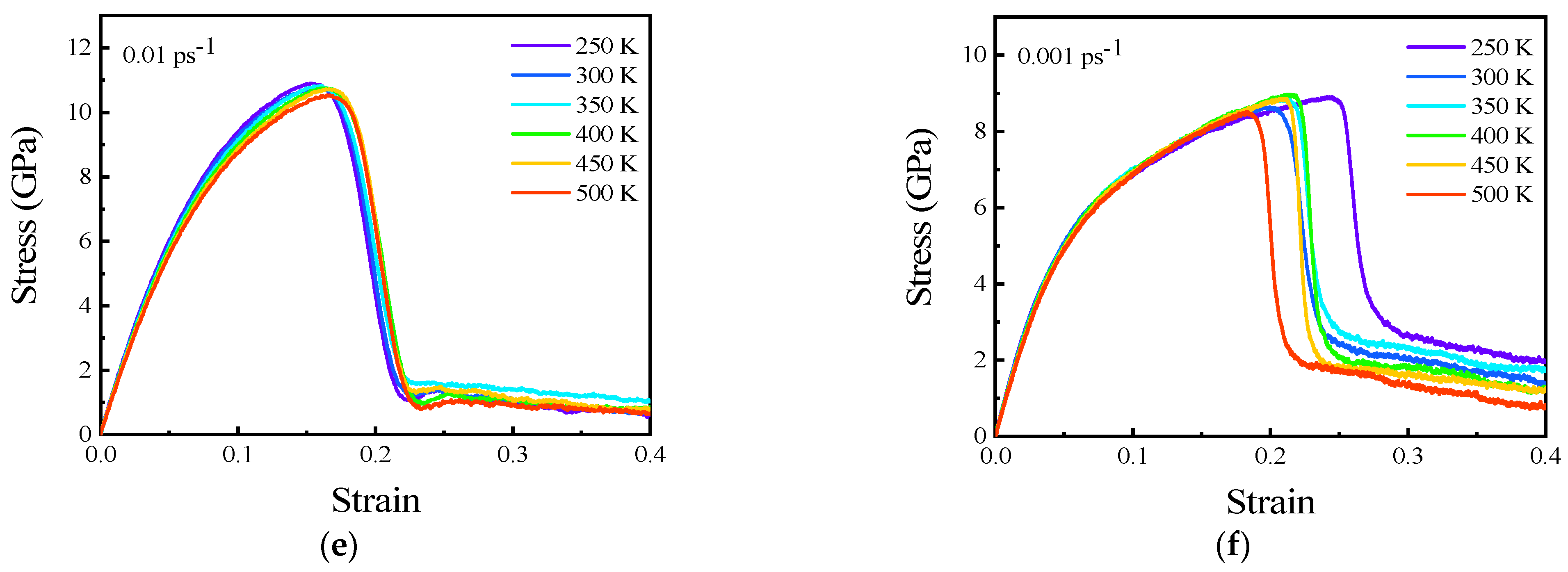
The stress–strain curves of the polycrystalline Cu6Sn5 at strain rates ranging from 0.001 to 100 ps−1 were recorded in the temperature range of 250 K to 500 K, as illustrated in Figure 4. The changing trends of all stress–strain curves are similar in the temperature range of 250–500 K, with the strain rate ranging from 0.001 to 100 ps−1. The stretching deformation shifted from the elastic stage to the plastic stage and then cracked. There is no yield phase and plastic deformation in this tensile process, which indicates that the elastic deformation is prominent, and the failure of the polycrystalline Cu6Sn5 at strain rates from 0.001 to 100 ps−1 is due to brittle fracture. It was also observed that the stress–strain curve at the tensile strain rate of 100 ps−1 was very close to that at the strain rate of 10 ps−1. This indicates that for a stain rate exceeding 10 ps−1, its effects on the stress–strain response are negligible. Research shows that the failure modes of materials can be affected by strain rate [4]. It was found that elastic deformation is dominant before UTS and exhibits a brittle failure when the polycrystal is stretched, with the strain rate ranging from 0.01 to 100 ps−1, as shown in Figure 4a–e. Plastic deformation occurs when the strain rate is less than 0.001 ps−1 despite the dominance of elastic deformation, as shown in Figure 4f. More information about the ductile performance under a low strain can be found in Section 3.5. The polycrystal exhibits obvious ductile deformation with strain rates lower than 0.001 ps−1. Therefore, 0.001 ps−1 was chosen as a boundary. Therefore, in this study, strain rates ranging from 0.001 to 100 ps−1 are defined as high strain rate stretching, and those less than 0.001 ps−1 are considered as low strain rate stretching.
According to the generalized Hooke’s Law, during linear elastic deformation, the stress () and strain () satisfy Equation (3), where E is Young’s modulus. Therefore, the slope of the linear part of the stress–strain curve is recorded as Young’s modulus.
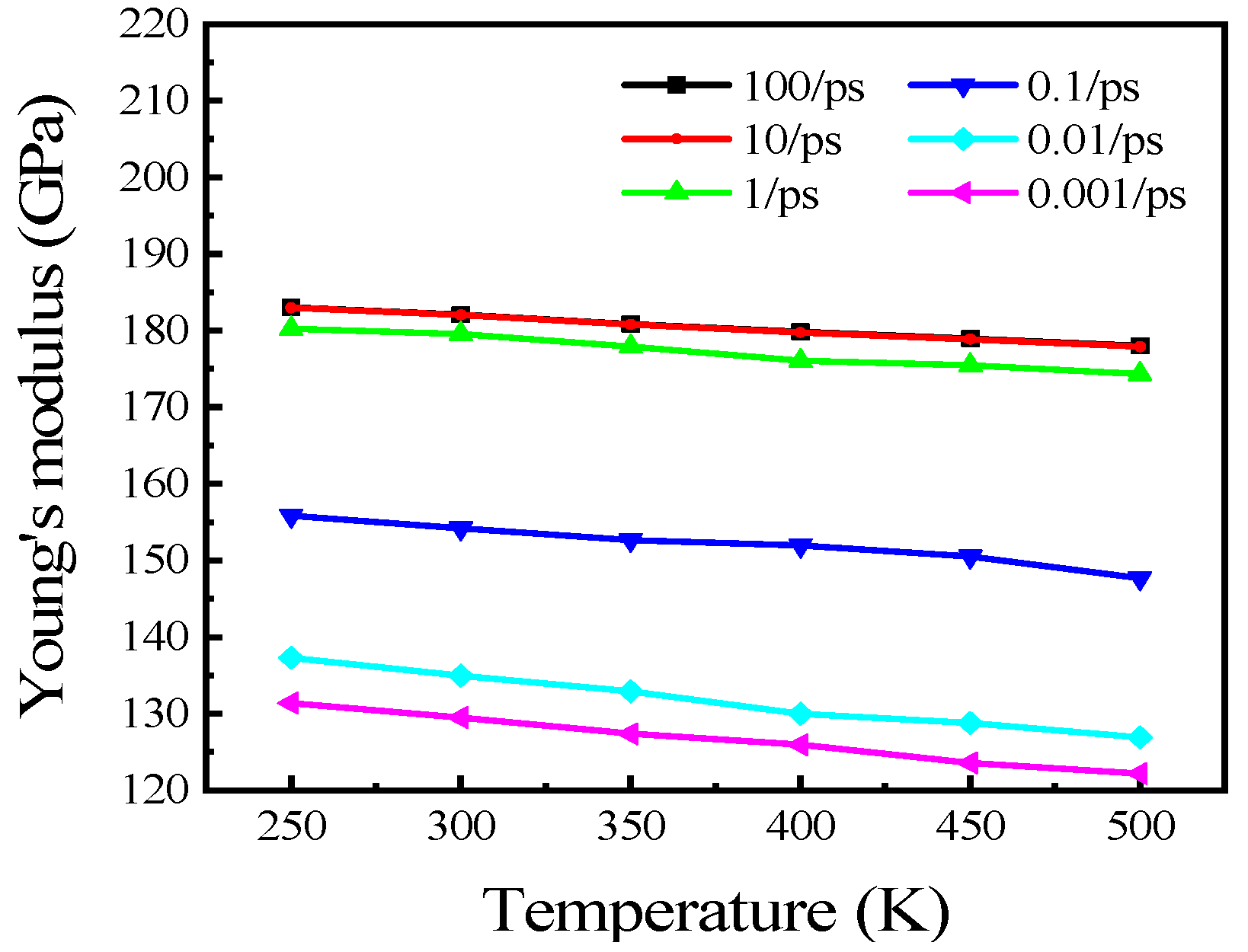
The calculated results of Young’s modulus according to Figure 4 are shown in Figure 5. It is observed that Young’s modulus decreases approximately linearly with increasing temperature at different strain rates. Young’s modulus decreases from 136.15 to 125.15 GPa, 137.29 to 126.90 GPa, 155.86 to 147.71 GPa, 180.26 to 174.33 GPa, 182.99 to 177.89 GPa, and 183.04 to 178.02 GPa when the temperature increases from 250 to 500 K at strain rates of 0.001, 0.01, 0.1, 1, 10, and 100 ps−1, respectively. The decreasing rates of Young’s modulus are 44.03, 41.57, 32.61, 23.71, 20.37, and 20.07 MPa/K, respectively. Young’s modulus is the tensile modulus, which represents the ability of a material to resist elastic tensile deformation. Thus, the ability of the polycrystalline Cu6Sn5 to resist tensile deformation at a lower temperature is greater than that at a higher temperature.
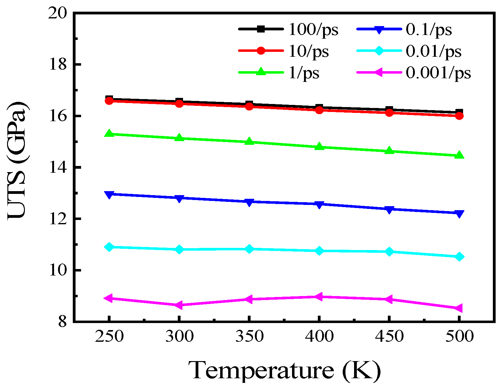
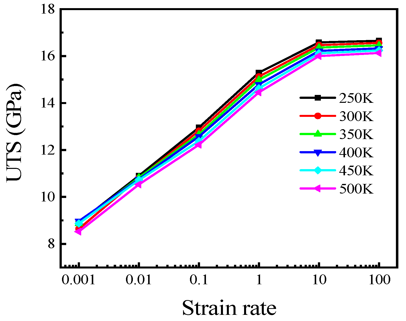
The UTSs at different temperatures are shown in Figure 6. It is observed that the UTS decreases with an increase in temperature when the strain rate is kept constant. It decreases from 8.91 to 8.53 GPa, 10.90 to 10.53 GPa, 12.96 to 12.22 GPa, 15.29 to 14.46 GPa, 16.58 to 16.00 GPa, and 16.65 to 16.13 GPa when temperature increasing from 250 to 500 K at strain rates of 0.001, 0.01, 0.1, 1, 10, and 100 ps−1, respectively. Moreover, it is observed that most strains at corresponding UTSs are nearly the same, while the strain rates are maintained constant, which indicates that temperature has little effect on the strain of the UTS during stretching at a strain rate ranging from 0.001 to 1 ps−1, as shown in Figure 4.
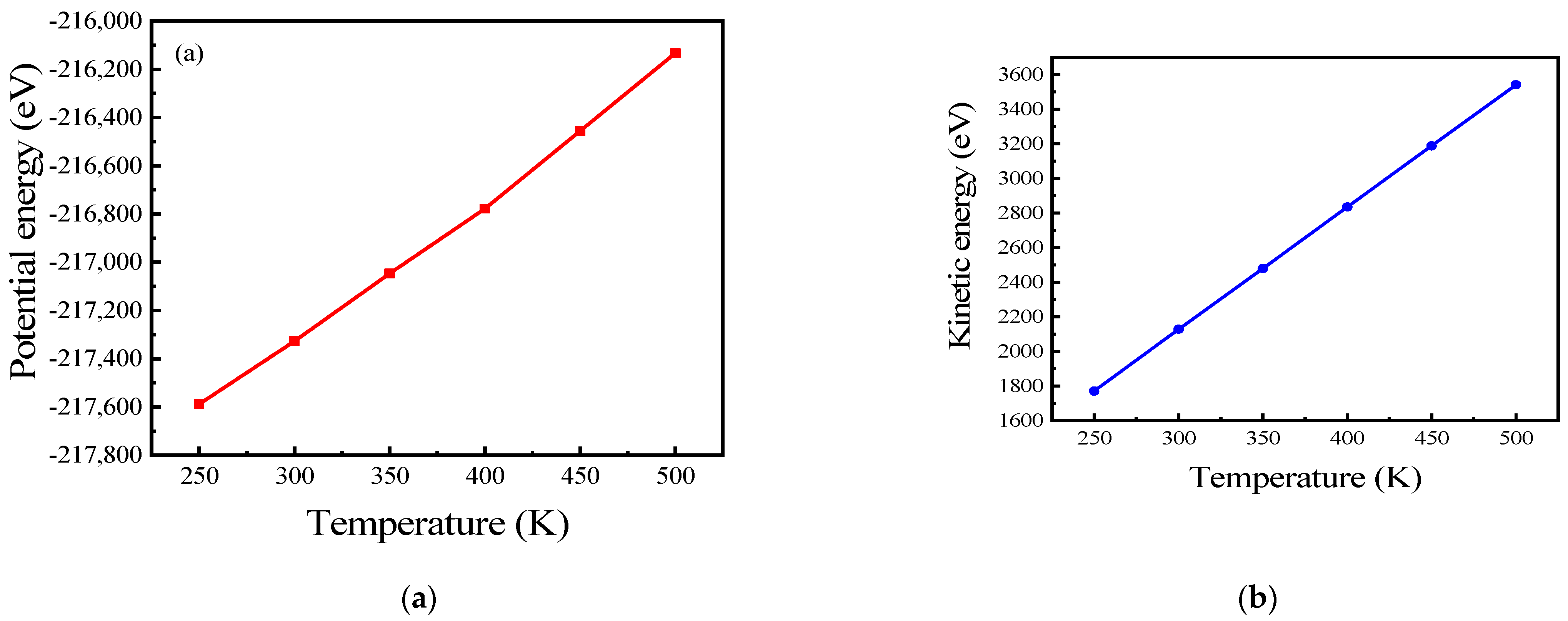
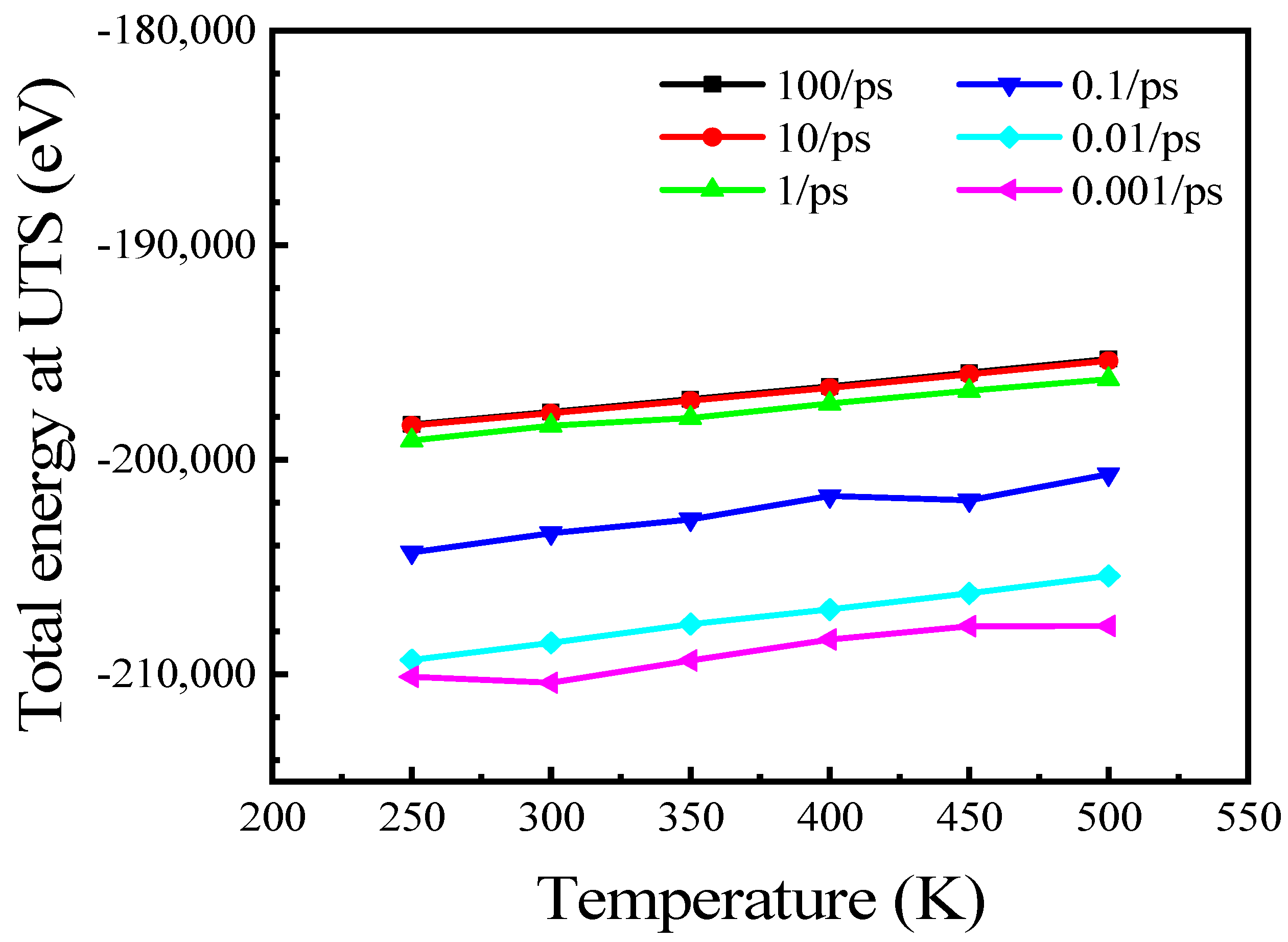
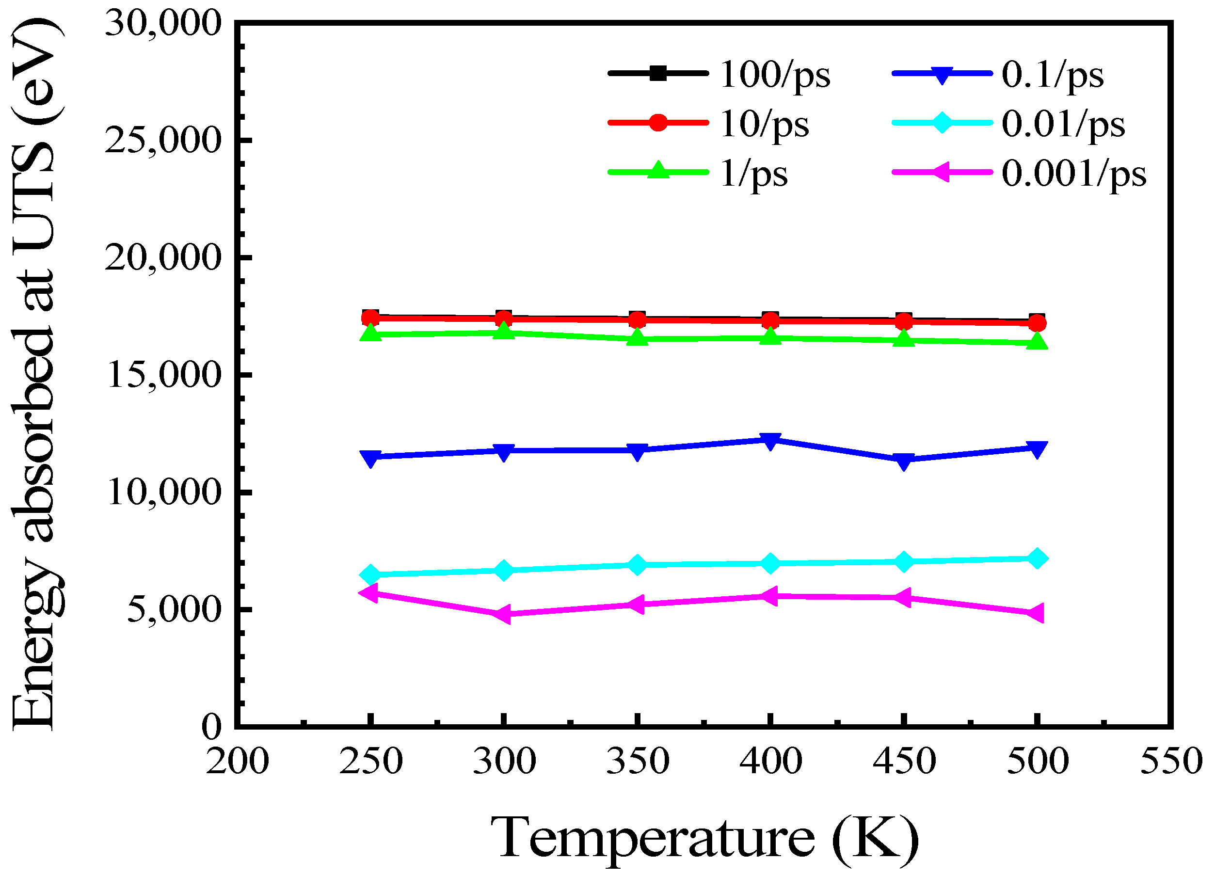
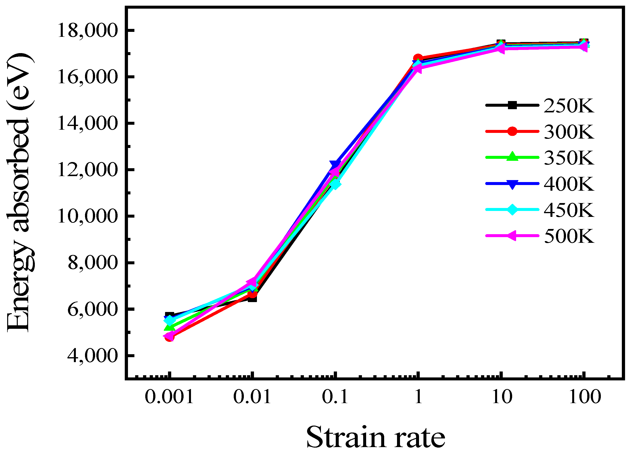
From what has been discussed above, the temperature can affect Young’s modulus and UTS during stretching, and they both decrease with increasing temperature. This is because both the initial kinetic energy and potential energy of the relaxed system at a high temperature are higher than those at a low temperature, as shown in Figure 7. The potential energy represents the interaction between atoms; thus, the stability of a system increases with a decrease in the potential. On the other hand, kinetic energy represents the random thermal motion between atoms. With an increase in temperature, the atomic motion is more intense, thus leading to an increase in the kinetic energy and, consequently, a decrease in atomic interactions. As the total energy is the sum of the potential and kinetic energy, the initial total energy of the system also increases as the temperature increases. The total energy of the system at the UTS and the energy absorbed during the stretching process (the total energy at UTS minus the initial total energy) are shown in Figure 8 and Figure 9, respectively. The total energy of the system at the UTS increases with the increase in temperature, while the absorbed energy is almost constant. The change in the total energy is due to the initial energy differences, while the energy absorbed by the system is almost unaffected by the temperature at a constant strain rate stretching.
The above reasons account for the decrease in Young’s modulus and UTS when the temperature increases. Both Young’s modulus and UTS decrease approximately linearly with increasing temperature, but the linearity at higher strain rates (0.01 to 100 ps−1) is better than that at lower strain rates (0.001 ps−1), as shown in Figure 5 and Figure 6. According to the previous description, 0.001 ps−1 is the critical strain rate between low and high strain rates. We infer that it may be a ductile–brittle mixed failure when stretching at this strain rate. The energy values absorbed at UTS with different temperatures are shown in Figure 9. It can be found that the absorbed energy exhibits inconsistency according to the temperature variation when stretching with 0.001/ps. Therefore, it can be concluded that the above reasons lead to the inconsistency of UTS with temperature change. This means that as the strain rate decreases, the polycrystalline Cu6Sn5 is subjected to more complex stresses when stretching. The strain rate effects on tensile properties of polycrystalline will be discussed in the next section.
3.4. High Strain Rate Effects on Tensile Properties of Polycrystalline Cu6Sn5
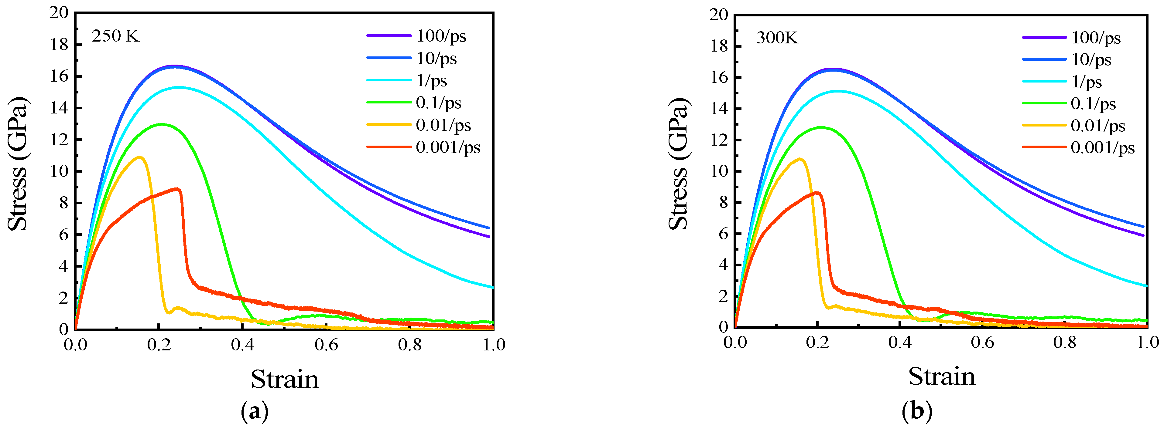
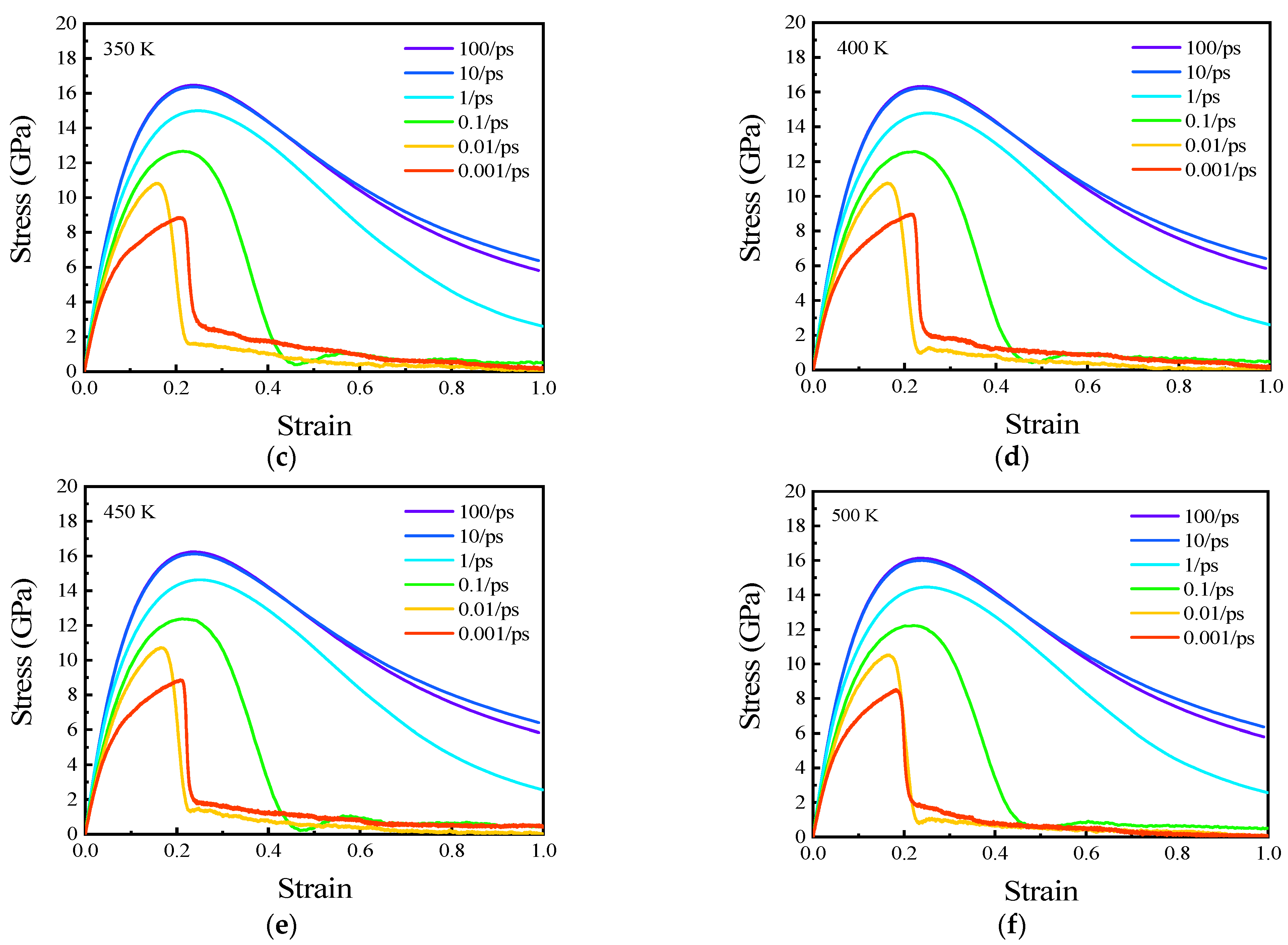
Figure 10 shows the stress–strain curves with strain rate changing from 0.001 to 100 ps−1 at (a) 250 K, (b) 300 K, (c) 350 K, (d) 400 K, (e) 450 K, and (f) 500 K. The strain rates changing from 0.001 to 100 ps−1 are denoted as high strain rates in this study. With an increase in the strain rate, the stress at the corresponding strain before the UTS is larger than that at a lower strain rate, and the plastic deformation is more significant at lower strain rates. Despite this, elastic deformation is predominant at high strain rate stretching. When elastic deformation is dominant in the stretching process (strain rate from 0.001 to 100 ps−1), the corresponding strain of the UTS increases with the increase in the strain rate, which indicates that the tensile strength of the IMC at a high strain rate is higher than that at a lower strain rate. However, the stress-train response at the strain rate of 100 ps−1 is very close to that at the strain rate of 10 ps−1. This means that when the strain rate is sufficiently large, the effect of the stress–strain response is almost negligible in this study.
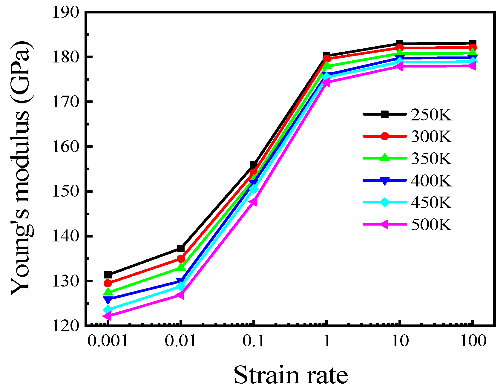
Young’s modulus and UTS were also calculated based on the stress–strain curves in Figure 10. The results are shown in Figure 11 and Figure 12. Logarithmic coordinates were chosen for abscissa in both figures and the curves reveal the existence of logarithmic relationships between both Young’s modulus and UTS to the strain rate. Moreover, they both increase with increasing strain rates. The mechanical properties of Cu3Sn also exhibit a similar logarithmic trend [22].
We can presume that due to fast stretching at high strain rates, dislocations among grain boundaries occur later; thus, the effect of the dislocations is negligible. In this case, the forces at all positions of the polycrystalline Cu6Sn5 are almost the same. Therefore, the ability of the polycrystal to resist tensile deformation is enhanced, thus leading to an increase in Young’s modulus and UTS.
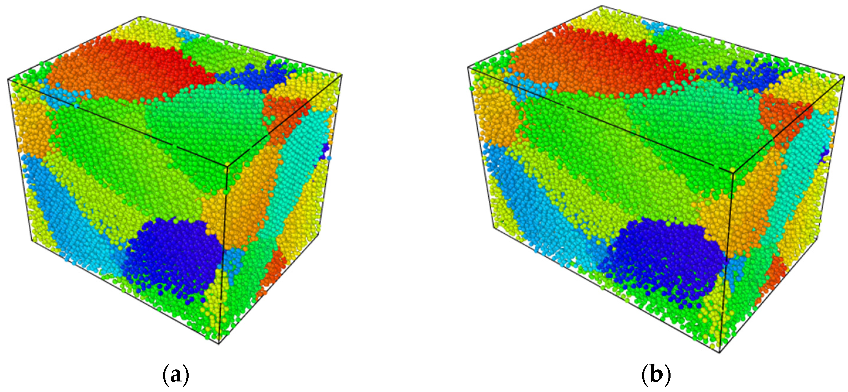
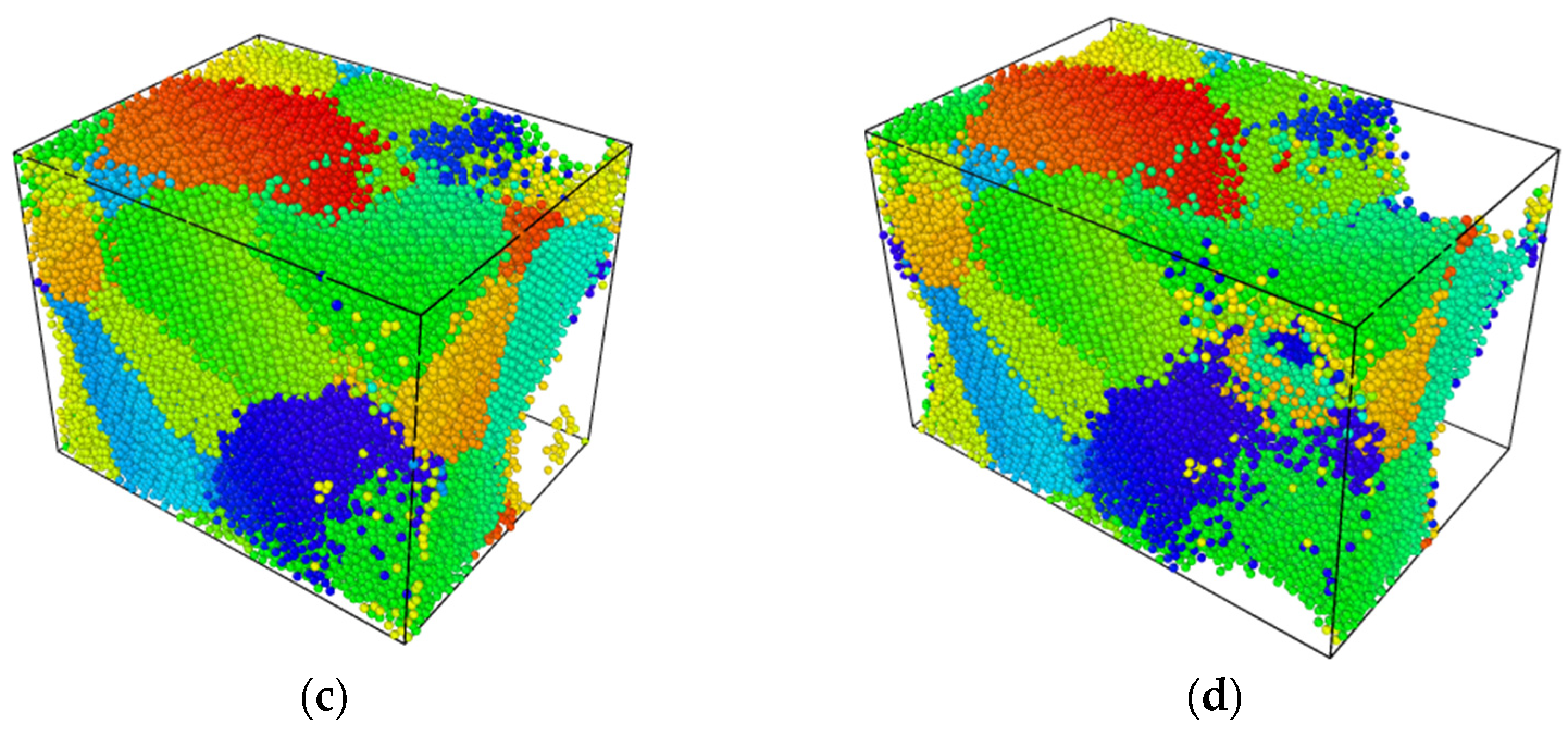
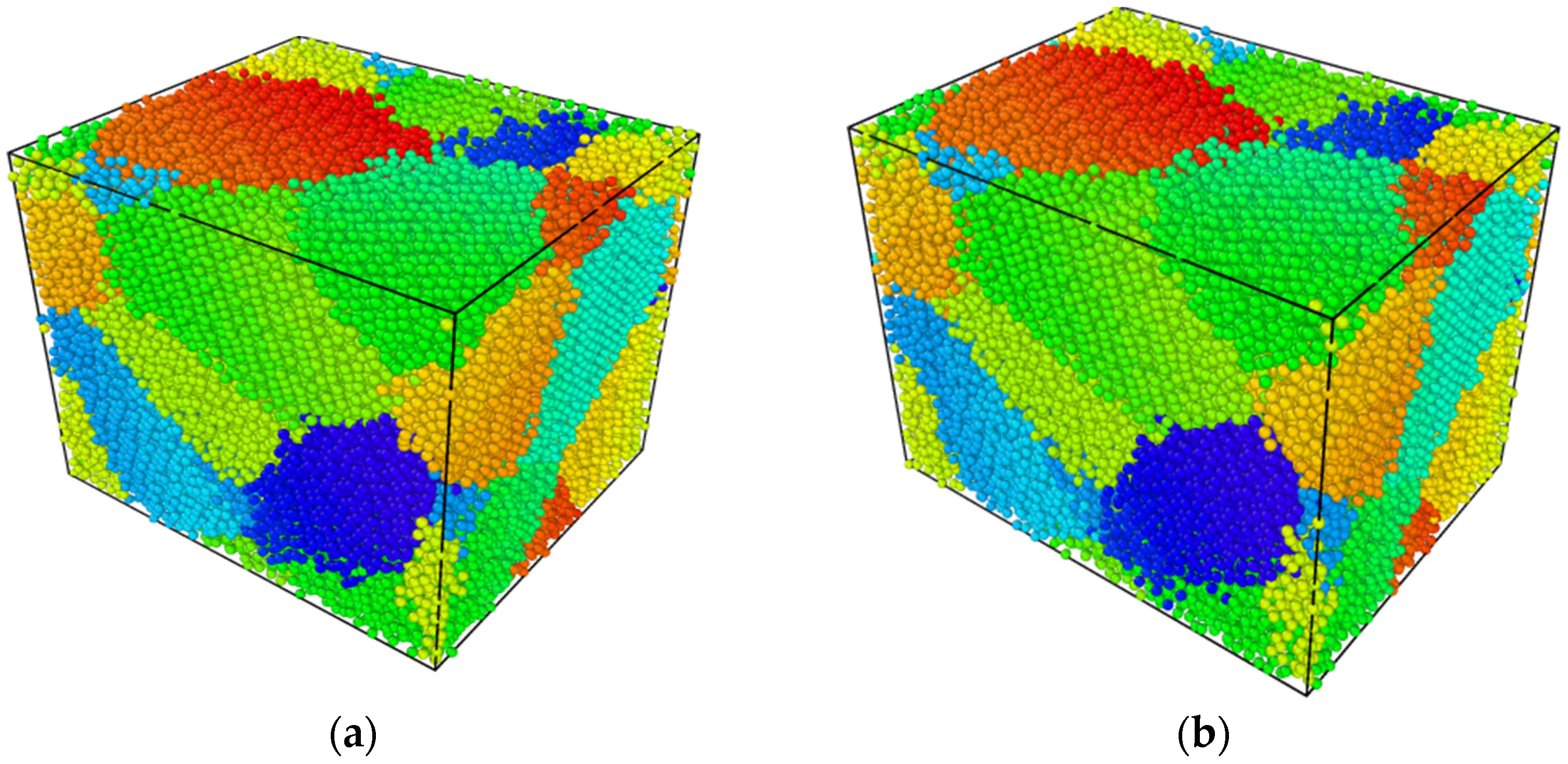
To further evaluate the influence of the strain rate on the deformation of the polycrystalline Cu6Sn5, polycrystals with 0.25 and 0.5 strains at 300 K are shown in Figure 13. All the grains are uniformly deformed when stretched at the strain rate of 1 ps−1, and the defects between the grain boundaries, even the elongation up to 0.5, are negligible, as shown in Figure 13a,b. This is because the polycrystals are destroyed before the dislocations between the grain boundaries occur owing to the speed of the tensile velocity. However, the deformation characteristics change exponentially with decreasing strain rate. When the strain rate is reduced to 0.001 ps−1, there is adequate time for the grain boundaries to dislocate, which leads to defects in the polycrystal, as shown in Figure 13c,d. In addition, with a decrease in the strain rate, the dislocations are more significant among the grain boundaries at the same strain, which results in a decrease in the UTS of the material, as shown in Figure 12.
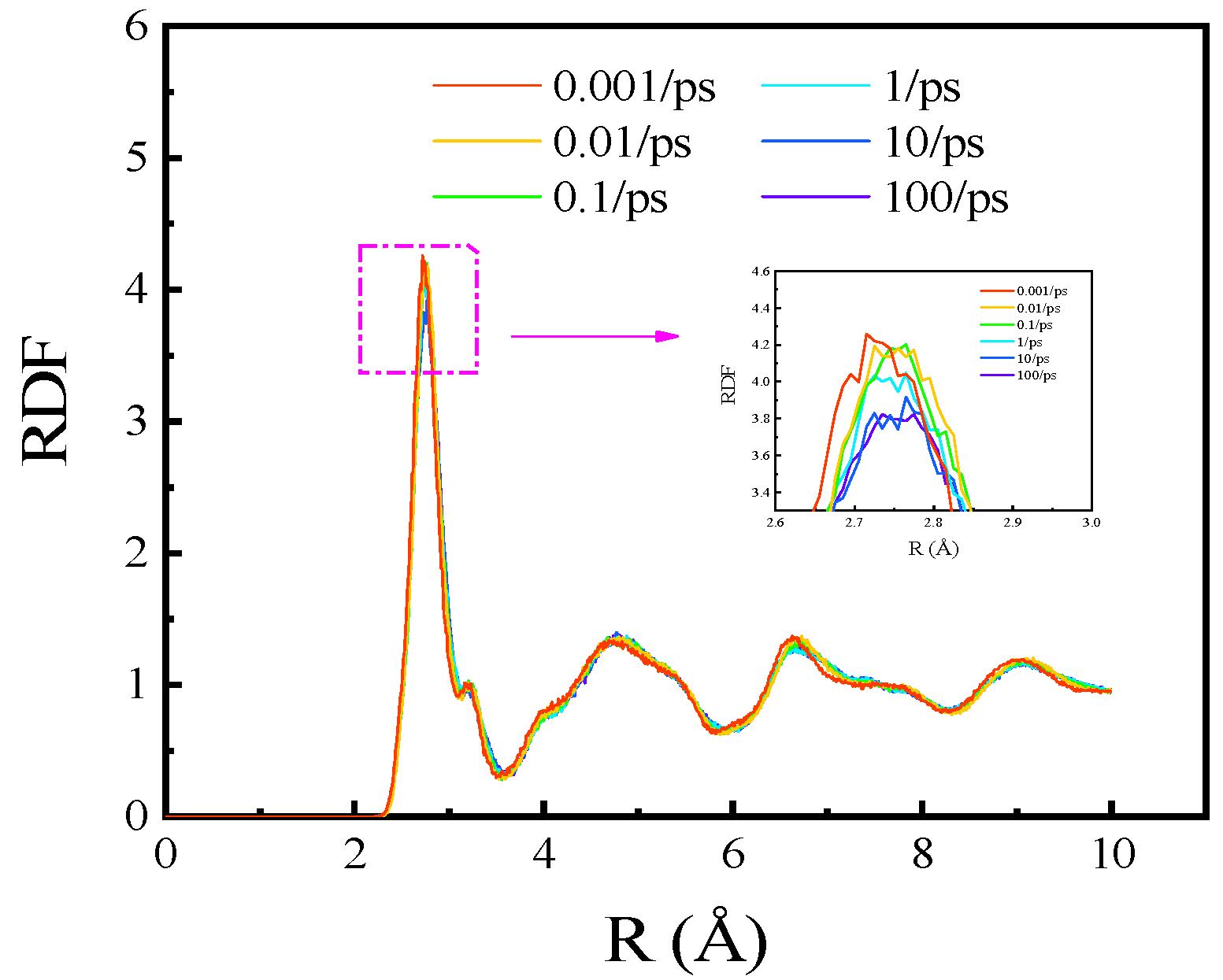
The radial distribution function (RDF) is the most common mathematical language used to describe the microstructure of liquid and amorphous materials. It denotes the ratio of the local density of a molecule to the bulk density at a distance of r around a central atom. In the binary intermetallic compounds system, the RDF for atoms α and β can be calculated as Equation (4) [16].
where V represents the volume of the system and n(r) the number of particles, which can be found in the shell from r to r + Δr [16].
The calculated RDFs at different strain rates when the strain is 0.1 are shown in Figure 14. The peak value of the RDFs varies with the strain rates and then gradually approaches 1 with increasing r. It can be seen from the local enlargement that the RDF decreases with an increasing strain rate. This is because an increase in the strain rate causes more disorder in the atomic structure, which increases amorphization and hinders the formation of slip planes [34,35]. As there is no dislocation surface, the UTS improves [16]. The analysis results here are consistent with those shown in Figure 11. The energy absorbed by the system with different strain rates at the UTS is shown in Figure 15. As the strain rate increases to a larger value, more energy is absorbed by the system when reaching the UTS. Figure 10 shows that the corresponding strain value at the UTS changes over a small range; thus, the increased stress causes more energy to be absorbed.
3.5. Low Strain Rate Effects on Tensile Properties of Polycrystalline Cu6Sn5
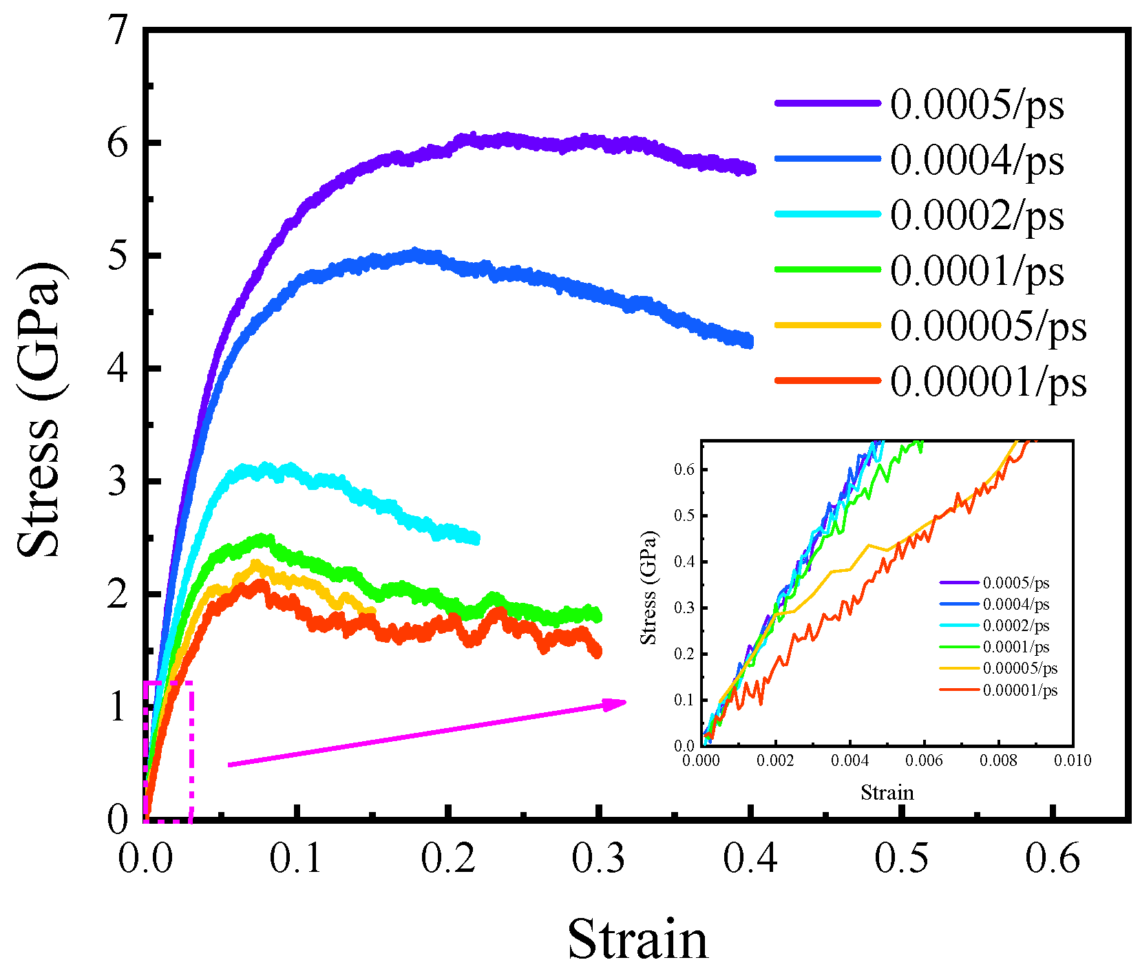
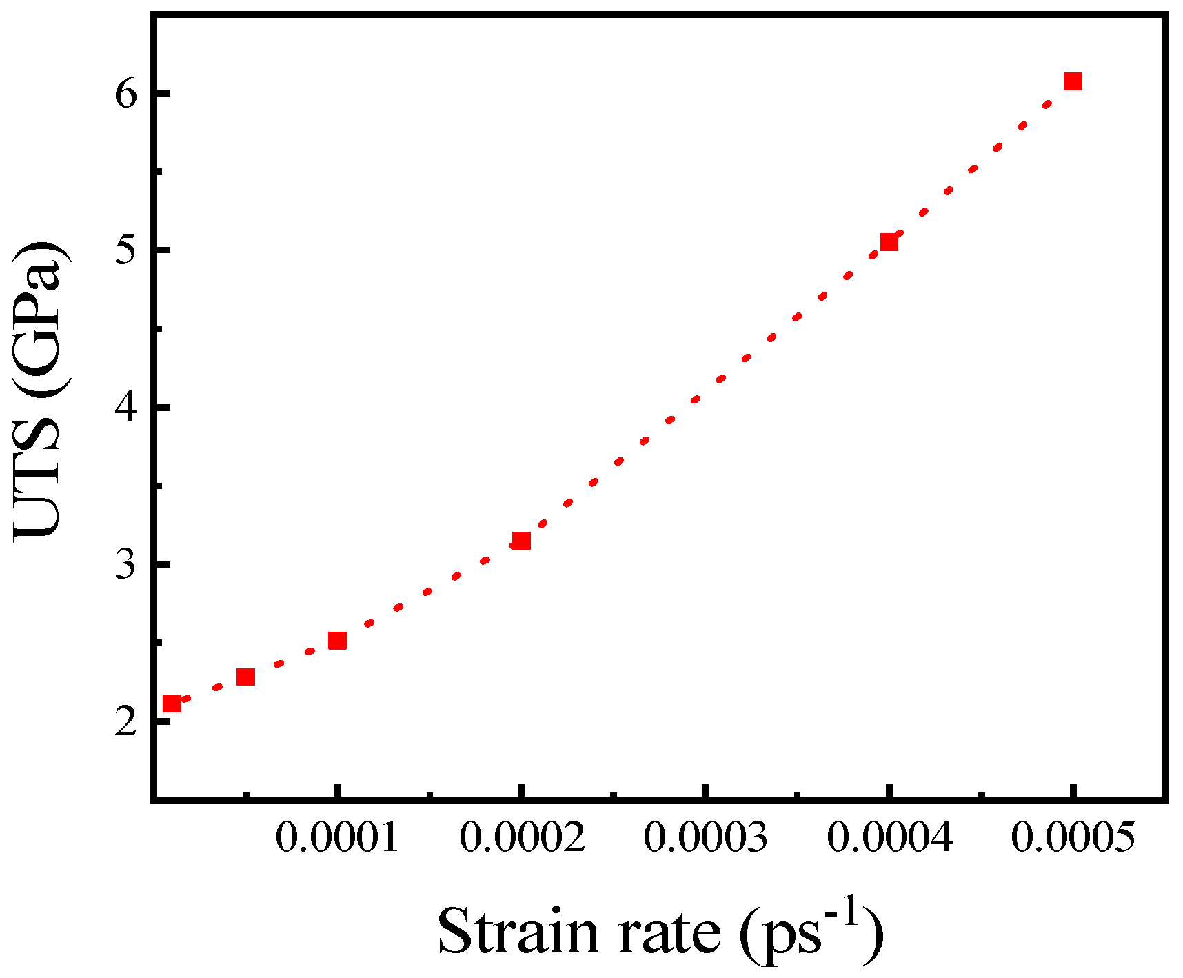
The stress-strain curves at 300 K with the strain rate from 0.00001 to 0.0005 ps−1 are shown in Figure 16. When the strain rate is lower than 0.001 ps−1, the stress does not decrease rapidly after the UTS but shows an obvious stage of plastic deformation. Within this strain rate range, the UTS still decreases with a decrease in the strain rate. However, at high strain rates, the relationship between UTS and strain rate is approximately logarithmic, while at low strain rates, the relationship between UTS and strain rate is approximately quadratic, as shown in Figure 17. As the strain rate decreases, the UTS gradually approaches a constant. The polycrystals when the strain rate is 0.00001 and the strains are 0.2 and 0.4 are shown in Figure 18. It can be found that there are no obvious dislocations when stretching at this strain rate. This is because when the tensile velocity is too low, there is sufficient time for stress relaxation. As seen from the local magnification of Figure 14, with a decrease in the strain rate, the plastic deformation of the polycrystalline Cu6Sn5 becomes more significant.
4. Conclusions
The tensile properties of the polycrystalline Cu6Sn5 were investigated at different temperatures and strain rates via the MD simulation. Based on the polycrystalline Cu6Sn5 created through Voronoi tessellation by Atomsk, the stress–strain curves at different temperatures and strain rates were obtained, from which Young’s modulus and UTS were extracted. The stress–strain response could be affected by both the temperature and strain rate. The conclusions are as follows:
- (1)
- Young’s modulus and UTS decreased approximately linearly when the temperature increased from 250 to 500 K at high strain rates. The effect of temperature was relatively small compared with that of strain rate. The effect of temperature on mechanical properties was approximately negative linear, while the effect of strain rate on mechanical properties was approximately exponential with high strain rates.
- (2)
- The strain rate affected the deformation characteristics of the IMC. When it ranged from 0.001 to 100 ps−1, the elastic deformation was the dominant deformation in the stretching process. On the other hand, with a decrease in the strain rate, the plastic deformation was gradually more significant. When the strain rate was between 0.00001 and 0.0005 ps−1, the plastic deformation characteristics gradually appeared.
- (3)
- The strain rate affected the tensile strength of the IMC. At high strain rates (from 0.001 to 1 ps−1), Young’s modulus and UTS decreased with decreasing strain rate, and they exhibited exponential relationships with the strain rate. At low strain rates (from 0.00001 to 0.0005 ps−1), the relation between the UTS and strain rate was quadratic.
Author Contributions
Conceptualization, W.H. and K.P.; funding acquisition, K.P. and Y.G.; investigation, W.H. and J.Z.; methodology, W.H. and K.P.; software, W.H.; validation, J.Z.; writing—original draft preparation, W.H.; writing—review and editing, K.P. and J.Z. All authors have read and agreed to the published version of the manuscript.
Funding
This study was sponsored by the National Natural Science Foundation of China (NSFC 61474032), the National Defense Basic Scientific Research Program of China under Grant JSZL2018204B003, and Self-Topic Fund of Engineering Research Center of Electronic Information Materials and Devices Nos. EIMD-AA202007.
Data Availability Statement
All the data supporting reported results can be found in this manuscript.
Conflicts of Interest
The authors declare that they have no conflict of interest.
References
- Qiu, H.; Hu, X.; Li, S.; Wan, Y.; Li, Q. Shear strength and fracture surface analysis of lead-free solder joints with high fraction of IMCs. Vacuum 2020, 180, 109611. [Google Scholar] [CrossRef]
- Zhao, M.; Zhang, L.; Liu, Z.Q.; Xiong, M.Y.; Sun, L. Structure and properties of Sn-Cu lead-free solders in electronics packaging. Sci. Technol. Adv. Mater. 2019, 20, 421–444. [Google Scholar] [CrossRef] [PubMed] [Green Version]
- Xiong, M.Y.; Zhang, L. Interface reaction and intermetallic compound growth behavior of Sn-Ag-Cu lead-free solder joints on different substrates in electronic packaging. J. Mater. Sci. 2018, 54, 1741–1768. [Google Scholar] [CrossRef]
- Hu, X.; Xu, T.; Keer, L.M.; Li, Y.; Jiang, X. Shear strength and fracture behavior of reflowed Sn3.0Ag0.5Cu/Cu solder joints under various strain rates. J. Alloys Compd. 2017, 690, 720–729. [Google Scholar] [CrossRef]
- Yin, Z.; Sun, F.; Guo, M. Investigation of Elevated Temperature Mechanical Properties of Intermetallic Compounds in the Cu-Sn System Using Nanoindentation. J. Electron. Packag. 2020, 142, 021004. [Google Scholar] [CrossRef]
- Yu, C.F.; Cheng, H.C.; Chen, W.H. Molecular dynamics calculations and nanoindentation testing of the strain-rate and size dependent material properties of Cu3Sn IMC. In Proceedings of the 2010 5th International Microsystems Packaging Assembly and Circuits Technology Conference, Taipei, Taiwan, 20–22 October 2010. [Google Scholar] [CrossRef]
- Xiao, G.S.; Yang, X.X.; Yuan, G.Z.; Li, Z.G.; Shu, X.F. Mechanical properties of intermetallic compounds at the Sn-3.0Ag-0.5Cu/Cu joint interface using nanoindentation. Mater. Des. 2015, 88, 520–527. [Google Scholar] [CrossRef]
- Bi, X.; Hu, X.; Jiang, X.; Li, Q. Effect of Cu additions on mechanical properties of Ni3Sn4-based intermetallic compounds: First-principles calculations and nano-indentation measurements. Vacuum 2019, 164, 7–14. [Google Scholar] [CrossRef]
- Haseeb, A.; Rahman, A.; Chia, P.Y. Nanoindentation creep on Cu3Sn, Cu6Sn5 and (Cu, Ni)6Sn5 intermetallic compounds grown in electrodeposited multilayered thin film. J. Mater. Sci. Mater. Electron. 2018, 29, 1258–1263. [Google Scholar] [CrossRef]
- Marques, V.M.F.; Johnston, C.; Grant, P.S. Nanomechanical characterization of Sn–Ag–Cu/Cu joints—Part 1: Young’s modulus, hardness and deformation mechanisms as a function of temperature. Acta Mater. 2013, 61, 2460–2470. [Google Scholar] [CrossRef]
- Rahman, A.Z.M.S.; Chia, P.Y.; Haseeb, A.S.M.A. Mechanical properties of intermetallic compounds in electrodeposited multilayered thin film at small scale by nanoindentation. Mater. Lett. 2015, 147, 50–53. [Google Scholar] [CrossRef]
- Huang, W.; Pan, K.L.; Zhang, J.; Gong, Y.B. Effect of In-Doping on Mechanical Properties of Cu6Sn5-Based Intermetallic Compounds: A First-Principles Study. J. Electron. Mater. 2021, 50, 4164–4171. [Google Scholar] [CrossRef]
- Zhang, W.W.; Ma, Y.; Zhou, W.; Wu, P. The Structural, Elastic and Electronic Properties of Ni3−xCuxSn4 (x = 0, 0.5, 1 and 1.5) Intermetallic Compounds via Ab Initio Calculations. J. Electron. Mater. 2019, 48, 4533–4543. [Google Scholar] [CrossRef]
- Liang, L.; Zhang, J.; Xu, Y.; Zhang, Y.; Wang, W.; Yang, J. The effect of pressure and orientation on Cu-Cu3Sn interface reliability under isothermal ageing and monotonic traction via molecular dynamics investigation. Mater. Des. 2018, 149, 194–204. [Google Scholar] [CrossRef]
- Liu, B.H.; Chen, Y.L.; Hsu, Q.C. Study on Bonding and Shear Flow Phenomena of Shear Probe Test for BGA Solder Joint in Nano-Scale Analysis. In Proceedings of the ASME 2016 International Mechanical Engineering Congress and Exposition, Phoenix, AZ, USA, 11–17 November 2016. [Google Scholar] [CrossRef]
- Cheng, H.C.; Yu, C.F.; Chen, W.H. Size, Temperature, and Strain-Rate Dependence on Tensile Mechanical Behaviors of Ni3Sn4Intermetallic Compound Using Molecular Dynamics Simulation. J. Nanomater. 2014, 2014, 214510. [Google Scholar] [CrossRef] [Green Version]
- Gao, F.; Qu, J. Calculating the diffusivity of Cu and Sn in Cu3Sn intermetallic by molecular dynamics simulations. Mater. Lett. 2012, 73, 92–94. [Google Scholar] [CrossRef]
- Chen, W.H.; Yu, C.F.; Cheng, H.C.; Lu, S.T. Crystal size and direction dependence of the elastic properties of Cu3Sn through molecular dynamics simulation and nanoindentation testing. Microelectron. Reliab. 2012, 52, 1699–1710. [Google Scholar] [CrossRef]
- Li, L.H.; Wang, W.L.; Wei, B. First-principle and molecular dynamics calculations for physical properties of Ni-Sn alloy system. Comput. Mater. Sci. 2015, 99, 274–284. [Google Scholar] [CrossRef]
- Choudhury, S.F.; Ladani, L. Local shear stress-strain response of Sn-3.5Ag/Cu solder joint with high fraction of intermetallic compounds: Experimental analysis. J. Alloys Compd. 2016, 680, 665–676. [Google Scholar] [CrossRef] [Green Version]
- Qin, F.; An, T.; Chen, N. Strain Rate Effects and Rate-Dependent Constitutive Models of Lead-Based and Lead-Free Solders. J. Appl Mech 2009, 77, 011008. [Google Scholar] [CrossRef]
- Cheng, H.C.; Yu, C.F.; Chen, W.H. Strain- and strain-rate-dependent mechanical properties and behaviors of Cu3Sn compound using molecular dynamics simulation. J. Mater. Sci. 2012, 47, 3103–3114. [Google Scholar] [CrossRef]
- Fan, J.T. High-rate squeezing process of bulk metallic glasses. Sci. Rep. 2017, 7, 45051. [Google Scholar] [CrossRef] [Green Version]
- Fan, J.T.; Yang, L.Q. Damage mechanisms of bulk metallic glasses under high-rate compression. Int. J. Impact. Eng. 2017, 106, 217–222. [Google Scholar] [CrossRef]
- Yang, L.; Fan, J.; Nam, V.B.; Rabczuk, T. A nanoscale study of the negative strain rate dependency of the strength of metallic glasses by molecular dynamics simulations. Phys. Chem. Chem. Phys. 2018, 20, 26552–26557. [Google Scholar] [CrossRef] [PubMed]
- Plimpton, S. Fast Parallel Algorithms for Short-range Molecular-Dynamics. J. Comput. Phys. 1995, 117, 1–19. [Google Scholar] [CrossRef] [Green Version]
- Baskes, M.I. Modified Embedded-Atom Potentials for Cubic Materials and Impurities. Phys. Rev. B 1992, 46, 2727–2742. [Google Scholar] [CrossRef]
- Larsson, A.K.; Stenberg, L.; Lidin, S. The superstructure of domain-twinned η′-Cu6Sn5. Acta Crystallogr. Sect. B 1994, 50, 636–643. [Google Scholar] [CrossRef]
- Aguilar, J.F.; Ravelo, R.; Baskes, M.I. Morphology and dynamics of 2D Sn-Cu alloys on (100) and (111) Cu surfaces. Modell. Simul. Mater. Sci. Eng. 2000, 8, 335–344. [Google Scholar] [CrossRef]
- Hirel, P. Atomsk: A tool for manipulating and converting atomic data files. Comput. Phys. Commun. 2015, 197, 212–219. [Google Scholar] [CrossRef]
- Lee, N.T.S.; Tan, V.B.C.; Lim, K.M. First-principles calculations of structural and mechanical properties of Cu6Sn5. Appl. Phys. Lett. 2006, 88. [Google Scholar] [CrossRef]
- Ghosh, G.; Asta, M. Phase stability, phase transformations, and elastic properties of Cu6Sn5: Ab initio calculations and experimental results. J. Mater. Res. 2005, 20, 3102–3117. [Google Scholar] [CrossRef]
- Thomas, R.; Yooseob, S.; Wenbin, W.; Shruti, R.; George, Z.V.; Jeffrey, W.K. Order in polycrystalline plasticity deformation fields: Short-range intermittency and long-range persistency. Int. J. Plast. 2020, 128, 102674. [Google Scholar] [CrossRef]
- Ikeda, H.; Qi, Y.; Cagin, T.; Samwer, K.; Johnson, W.L.; Goddard, W.A. Strain rate induced amorphization in metallic nanowires. Phys. Rev. Lett. 1999, 82, 2900–2903. [Google Scholar] [CrossRef] [Green Version]
- Zhou, M. A new look at the atomic level virial stress: On continuum-molecular system equivalence. Proc. Math. Phys. Eng. Sci. 2003, 459, 2347–2392. [Google Scholar] [CrossRef]
Figure 1.
Cu6Sn5 (η’ phase) cell structure [12].
Figure 1.
Cu6Sn5 (η’ phase) cell structure [12].

Figure 2.
Polycrystalline Cu6Sn5 of 100 Å × 100 Å × 100 Å with 10 grains.

Figure 3.
Stress–strains curves when stretching along x-, y-, and z-axis.

Figure 4.
Stress-strain curves of polycrystalline Cu6Sn5 at temperatures of (a) 100 ps−1, (b) 10 ps−1, (c) 1 ps−1, (d) 0.1 ps−1, (e) 0.01 ps−1, and (f) 0.001 ps−1.
Figure 4.
Stress-strain curves of polycrystalline Cu6Sn5 at temperatures of (a) 100 ps−1, (b) 10 ps−1, (c) 1 ps−1, (d) 0.1 ps−1, (e) 0.01 ps−1, and (f) 0.001 ps−1.


Figure 5.
Young’s modulus at different temperatures.

Figure 6.
UTS at different temperatures.

Figure 7.
Initial energy of the polycrystalline Cu6Sn5 of (a) potential energy and (b) kinetic energy.
Figure 7.
Initial energy of the polycrystalline Cu6Sn5 of (a) potential energy and (b) kinetic energy.

Figure 8.
Total energy at UTS with temperature increasing.

Figure 9.
Energy absorbed at UTS with temperature increasing.

Figure 10.
Stress–strain curves with strain rate changing from 0.001 to 100 ps−1 at (a) 250 K, (b) 300 K, (c) 350 K, (d) 400 K, (e) 450 K, and (f) 500 K.
Figure 10.
Stress–strain curves with strain rate changing from 0.001 to 100 ps−1 at (a) 250 K, (b) 300 K, (c) 350 K, (d) 400 K, (e) 450 K, and (f) 500 K.


Figure 11.
Young’s modulus at different strain rates.

Figure 12.
UTS at different strain rates.

Figure 13.
Polycrystals at different strain rates of (a) = 0.25, = 1 ps−1; (b) = 0.5, =1 ps−1; (c) = 0.25, = 0.01 ps−1; (d) = 0.5, = 0.01 ps−1.
Figure 13.
Polycrystals at different strain rates of (a) = 0.25, = 1 ps−1; (b) = 0.5, =1 ps−1; (c) = 0.25, = 0.01 ps−1; (d) = 0.5, = 0.01 ps−1.


Figure 14.
RDF of 10% strain at different strain rates.

Figure 15.
Energy absorbed at UTS.

Figure 16.
Stress–strain curve at low strain rates.

Figure 17.
UTS at different strain rates.

Figure 18.
Polycrystals at strain of (a) 0.2; (b) 0.4.


Table 1.
Parameters of Cu6Sn5 MEAM potential.
| Elements | Ec (eV) | A | r0 (Å) | α | β(0) | β(1) | β(2) | β(3) | t(1) | t(2) | t(3) | ρ0 |
|---|---|---|---|---|---|---|---|---|---|---|---|---|
| Cu | 3.4 | 1.07 | 2.657 | 5.11 | 3.634 | 2.20 | 6.00 | 2.20 | 3.14 | 2.49 | 2.95 | 1 |
| Sn | 3.84 | 1 | 3.176 | 6.20 | 6.20 | 6.00 | 6.00 | 6.00 | 12.5 | 8.0 | −0.38 | 1 |
| Cu6Sn5 | 4.03 | 2.907 | 5.38 |
Table 2.
Screen parameters of the MEAM.
| (Cu, Cu, Cu) | (Cu, Cu, Sn) | (Cu, Sn, Cu) | (Sn, Sn, Sn) | (Sn, Cu, Sn) | (Sn, Sn, Cu) | |
|---|---|---|---|---|---|---|
| Cmin | 0.8 | 0.8 | 0.8 | 1.29 | 0.8 | 0.8 |
| Cmax | 2.8 | 2.8 | 2.8 | 4.43 | 2.8 | 2.8 |
Table 3.
Stiffness constants of monocrystalline Cu6Sn5.
| Stiffness Constants (GPa) | C11 | C22 | C33 | C12 | C13 | C23 | C44 | C55 | C66 |
|---|---|---|---|---|---|---|---|---|---|
| Our MD | 144.52 | 160.15 | 133.29 | 52.25 | 55.10 | 68.07 | 40.91 | 46.26 | 43.67 |
| Lee et al. [31] | 156.4 | 165.2 | 155.8 | 62.2 | 69.4 | 60.6 | 42.3 | 51.9 | 48.0 |
Publisher’s Note: MDPI stays neutral with regard to jurisdictional claims in published maps and institutional affiliations. |
© 2021 by the authors. Licensee MDPI, Basel, Switzerland. This article is an open access article distributed under the terms and conditions of the Creative Commons Attribution (CC BY) license (https://creativecommons.org/licenses/by/4.0/).
Share and Cite
MDPI and ACS Style
Huang, W.; Pan, K.; Zhang, J.; Gong, Y. Strain Rate and Temperature Effects on Tensile Properties of Polycrystalline Cu6Sn5 by Molecular Dynamic Simulation. Crystals 2021, 11, 1415. https://0-doi-org.brum.beds.ac.uk/10.3390/cryst11111415
AMA Style
Huang W, Pan K, Zhang J, Gong Y. Strain Rate and Temperature Effects on Tensile Properties of Polycrystalline Cu6Sn5 by Molecular Dynamic Simulation. Crystals. 2021; 11(11):1415. https://0-doi-org.brum.beds.ac.uk/10.3390/cryst11111415
Chicago/Turabian StyleHuang, Wei, Kailin Pan, Jian Zhang, and Yubing Gong. 2021. "Strain Rate and Temperature Effects on Tensile Properties of Polycrystalline Cu6Sn5 by Molecular Dynamic Simulation" Crystals 11, no. 11: 1415. https://0-doi-org.brum.beds.ac.uk/10.3390/cryst11111415
Note that from the first issue of 2016, this journal uses article numbers instead of page numbers. See further details here.