Article

Preparation of Flower-like Nickel-Based Bimetallic Organic Framework Electrodes for High-Efficiency Hybrid Supercapacitors

1
School of Chemical Engineering, Northeast Electric Power University, Jilin 132000, China
2
College of Marine Engineering, Jimei University, Xiamen 361000, China
3
School of Chemistry, Beihang University, Beijing 100191, China
*
Authors to whom correspondence should be addressed.
Submission received: 9 November 2021 / Revised: 15 November 2021 / Accepted: 17 November 2021 / Published: 21 November 2021
(This article belongs to the Special Issue Structure Property Relationship of Energy Storage Materials)

Abstract

:
Metal organic frameworks (MOFs) have been rapidly developed in the application of electrode materials due to their controllable morphology and ultra-high porosity. In this research, flower-like layered nickel-based bimetallic MOFs microspheres with different metal central ions were synthesized by solvothermal method. Compared with Ni-MOFs, the optimization of the specific capacitance of NiCo-MOFs and NiMn-MOFs was been confirmed. For example, the specific capacitance of NiCo-MOFs can reach 882 F·g−1 at 0.5 A·g−1 while maintaining satisfactory cycle life (the specific capacity remains 90.1% of the initial value after 3000 charge-discharge cycles at 5 A·g−1). In addition, the NiCo-MOFs//AC HSCs, which are composed of NiCo-MOFs and activated carbon (AC), achieved a maximum energy density of 18.33 Wh·kg−1 at a power density of 400 W·kg−1, and showed satisfactory cycle life (82.4% after 3000 cycles). These outstanding electrochemical properties can be ascribed to the synergistic effect between metal ions, the optimized conductivity, and the unique layered stacked flower structure, which provides a smooth transmission channel for electrons/ions. In addition, this research gives a general method for the application of MOFs in the field of supercapacitors.

1. Introduction

Recently, serious deterioration of the environment and rapid depletion of energy resources have accelerated the exploration of green high-performance energy storage devices [1,2]. Currently, as an emerging large-capacity energy storage device, supercapacitors have shown enormous potential development benefits due to their surprising power density and superior cycle life, which are more suitable for the demands of energy storage devices in industrial equipment, transportation, and electronic equipment [3,4]. Typically, among the three types of electrode materials, electric double-layer capacitors (EDLCs), which are electrode materials represented by carbon-based materials, mainly store electric energy through electrostatic action, with long cycle life but low specific capacitance [5,6,7]. On the contrary, pseudocapacitance (PCs) materials represented by transition metal compounds and conductive polymers exhibit high specific capacitance due to the storage of electrical energy through redox reactions, but their cycle stability is greatly restricted [8,9,10,11]. It is worth noting that hybrid supercapacitors (HSCs) composed of EDLC-type anodes and battery-type cathodes are gradually showing surprising advantages in terms of operating voltage window and energy density. In order to further accelerate the exploration of HSCs, it is urgent and necessary to develop a new type of high-performance electrode material.
As an emerging crystalline porous material, MOFs effectively combine inorganic metal materials with organic ligands to display unique physicochemical characters, such as highly controllable structures and functions, high surface area and porosity, and abundant unsaturated metal sites [12,13]. It is also these unique structural features that provide an effective way for ion transmission and electrolyte penetration, making MOFs exhibit essential advantages in the field of supercapacitors [14,15]. The traditional MOFs synthesized with inorganic metal salts and organic ligands exhibit the defects of poor electrical conductivity and large steric hindrance due to their high organic content, which limits their direct application as electrode materials to a great extent [16,17]. Therefore, although a variety of MOF materials with different metal center ions have been directly applied to supercapacitors, including Fe, [18] Co, [1,19] Zn, [20] Zr, [21] In, [22] etc., most reported MOF electrode materials show unsatisfactory capacitances. Solutions to these problems can mainly be considered from the three aspects of porosity, specific surface area, and electrical conductivity [23,24]. Therefore, the regulation of the material morphology and structure of MOFs, as well as organic ligands and metal central ions, has been the focus of research.
Among the many kinds of MOF materials, Ni-MOF electrode materials are favored by researchers because of their excellent specific capacitance, rate, and stability [25,26,27,28]. At present, various different morphologies of MOFs have been used as electrode materials, for instance, Qu et al. prepared a pillared nickel-based MOF electrode material with a specific capacity of 522 F·g−1 at 1 A·g−1, while maintaining superior cycle stability [29]. Xu and his colleagues prepared one-dimensional Ni-based MOF nanorods, which also displayed exceptional energy storage performance [30]. With the gradual development of research, bimetallic MOFs have emerged in research on electrode materials. It is well recognized that the synergistic effect between bimetallic ions can greatly improve the energy storage capacity compared to single-metal MOF materials [31,32,33,34]. For example, Li et al. prepared a Ni/Zn-MOF material without using any template or surfactant, using the morphology of yolk shell with nanorods as the secondary unit, which exhibited excellent electrochemical properties (548 F·g−1 at 1.3 A·g−1) [35]. Typically, compared to pillared, nanorod, and yolk shell, the flower-like morphology is more conducive to the rapid progress of the reversible redox reaction due to its layered structure similar to petals. However, nickel-based bimetallic organic frameworks are currently rarely explored in the field of supercapacitors. Considering their great potential as electrode materials, it is necessary to conduct in-depth exploration to meet the urgent demand for electrode materials.
Here, we synthesized a series of bimetallic MOFs using p-benzenedicarboxylic acid as ligand and Ni2+ and Co2+ (Mn2+, Cu2+) as metal ion nodes by solvothermal method, introducing hydroxyl groups at the same time, and successfully confirmed the excellent electrochemical performance of NiCo-MOFs and NiMn-MOFs. The specific capacity of NiCo-MOFs, NiMn-MOFs, and NiCu-MOFs can reach 882, 747, and 345 F·g−1 at 0.5 A·g−1, respectively. In addition, NiCo-MOF electrode materials also achieve the best cycle life, which is much higher than the NiMn-MOF and NiCu-MOF electrodes. Meanwhile, the HSCs made by assembling NiCo-MOFs and AC also exhibited satisfactory energy density (18.33 Wh·kg−1 at 400 W·kg−1) and cycle life (82.4% after 3000 cycles). These conclusions illustrate that the introduction of Co2+ is beneficial to the improvement of the energy storage performance of MOF electrode materials and that NiCo-MOFs are expected to be a potential electrode material with long cycle life.

2. Materials and Methods

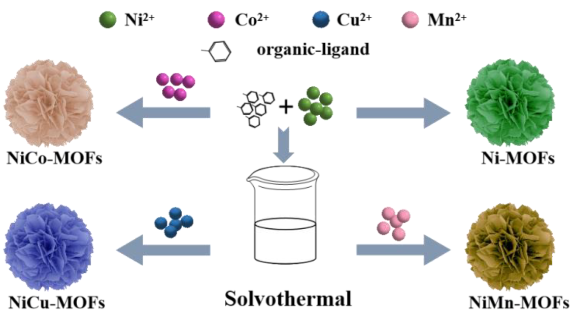
2.1. Sample Preparation

2.1.1. Preparation of Ni-MOFs

The preparation steps for Ni-MOFs referred to previous literature [36]. 0.192 g Ni(NO3)2·6H2O and 0.332 g p-benzenedicarboxylic acid (PTA) were uniformly dispersed in 40 mL dimethylformamide (DMF) through the process of magnetic stirring. Then, stirring continued while 4 mL NaOH (0.4 mol·L−1) was slowly added dropwise. After the dripping was completed, it was immediately transformed into a 100 mL Teflon-lined autoclave, with a reaction temperature and time of 100 °C and 8 h, respectively. Finally, the Ni-MOFs were obtained after centrifugation and drying.

2.1.2. Preparation of NiM-MOFs (M = Co, Mn, Cu)

0.192 g Ni(NO3)2·6H2O, 0.1178 g CoCl2·6H2O (0.084 g MnCl2·4H2O or 0.098 g CuCl2·2H2O), and 0.332 g PTA were uniformly dispersed in 40 mL DMF by magnetic stirring. Similarly, stirring continued while 4 mL NaOH (0.4 mol·L−1) was slowly added dropwise. After the dripping was completed, it was immediately moved to a 100 mL autoclave lined with polytetrafluoroethylene, with a reaction temperature and time of 100 °C and 8 h, respectively. Finally, the NiM-MOFs were obtained after centrifugation and drying. The fabrication process of Ni-MOFs and NiM-MOFs is shown in Scheme 1.

2.2. Characterization

The composition was tested by X-ray powder diffraction (XRD, XRD-7000 X, Shimadzu, Kyoto, Japan). X-ray photoelectron spectroscopy (XPS, monochromatic Al Kα radiation) further confirmed the elements valence. The morphology was analyzed by scanning electron microscope (Scanning Electron Microscope, SEM, XL-30 FEG, FEI, Eindhoven, The Netherlands); The energy-dispersive X-Ray spectroscopy (EDS) elemental mapping patterns proved the uniform distribution of the chemical elements in the sample. The specific surface area and pore size of samples were obtained by N2 adsorption–desorption isotherms (Micromeritics Tristar 3020, Norcross, Georgia, GA, USA).

2.3. Electrochemical Performance Measurement

The electrochemical property was investigated by cyclic voltammetry (CV), galvanostatic charge–discharge (GCD), and electrochemical impedance spectroscopy (EIS), all of which were carried out on a traditional three-electrode system. Specifically, the active material, acetylene black, and polytetrafluoroethylene (PTFE) emulsion were evenly mixed at a ratio of 8:1:1. The mixture was coated on the nickel foam according to the size of 1.0 cm × 1.0 cm, and dried to obtain the working electrode. The specific capacity can be obtained based on the above test; the formula is as follows:
C = I × Δ t m × Δ V
where I (A), Δt (s), m (g), and ΔV (V) are discharge current and time, mass of active material, and potential window, respectively.

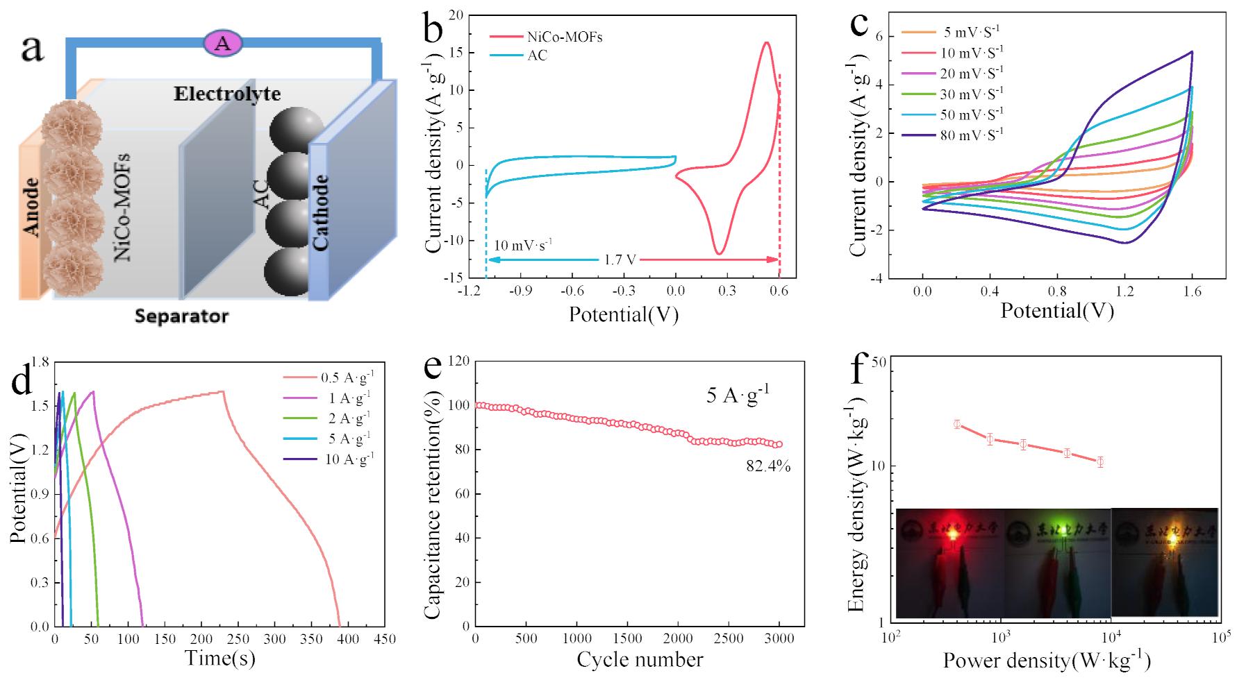
2.4. Fabrication and Measurements of HSCs

HSCs with NiCo-MOFs as cathodes and AC as anodes were prepared in order to study the application potential of the product. The charge storage capability (CV, GCD) was tested by CHI 660E potentiostat. At the same time, the energy density (E, Wh·kg−1) and power density (P, W·kg−1) were also investigated through the calculation formula [11]:
E = 1 2 C × Δ V 2
P = E Δ t ,
where C (F·g−1), ΔV (V), and Δt (s) are the specific capacitance of the HSCs, battery working potential, and discharge time, respectively.

3. Results

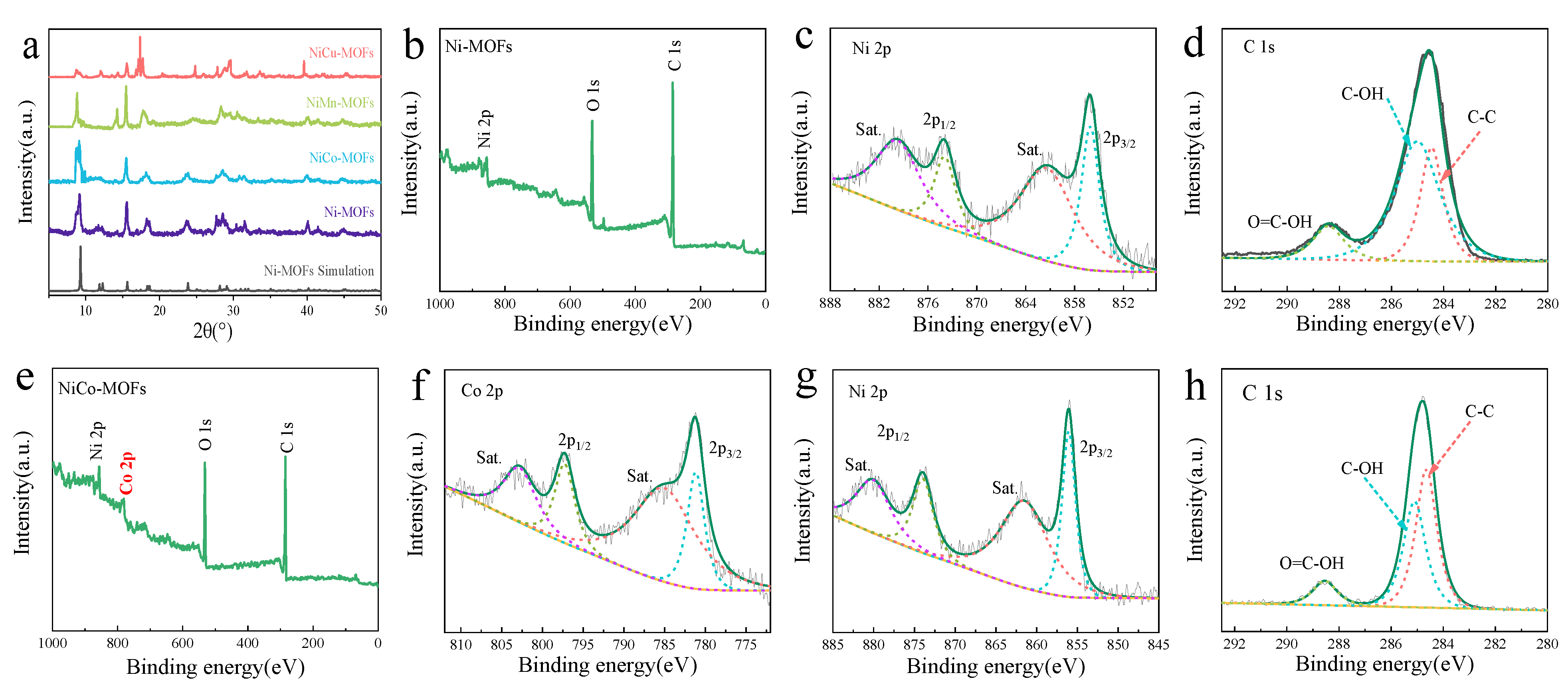
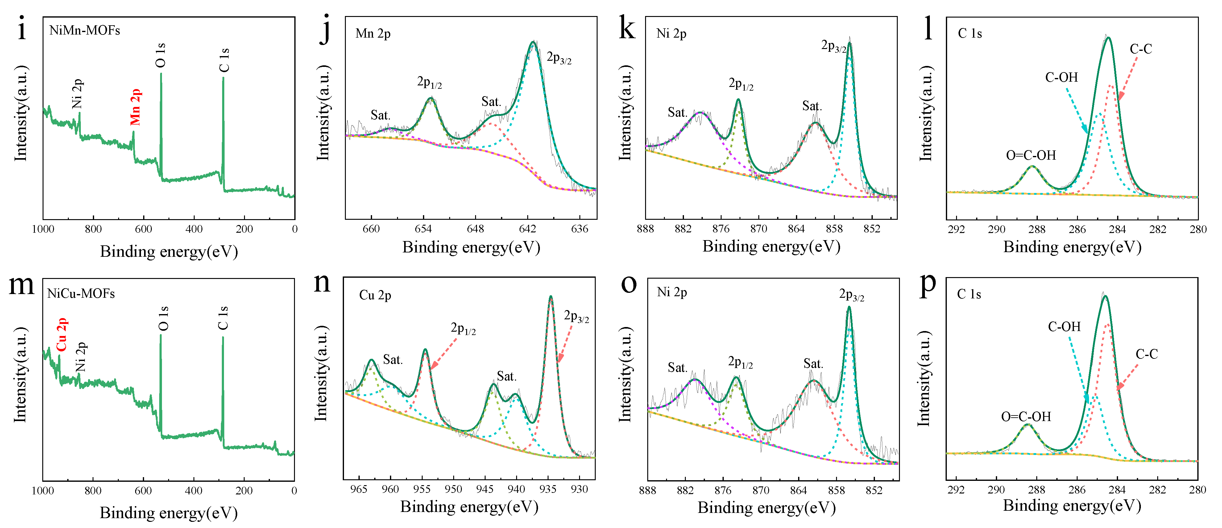
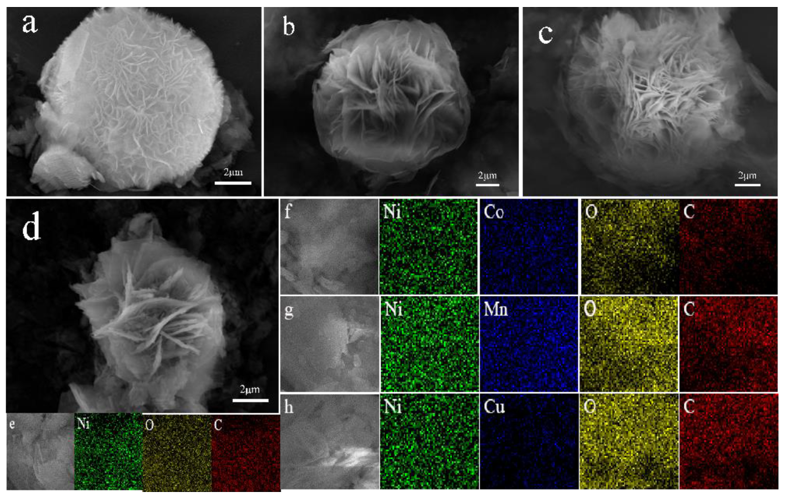
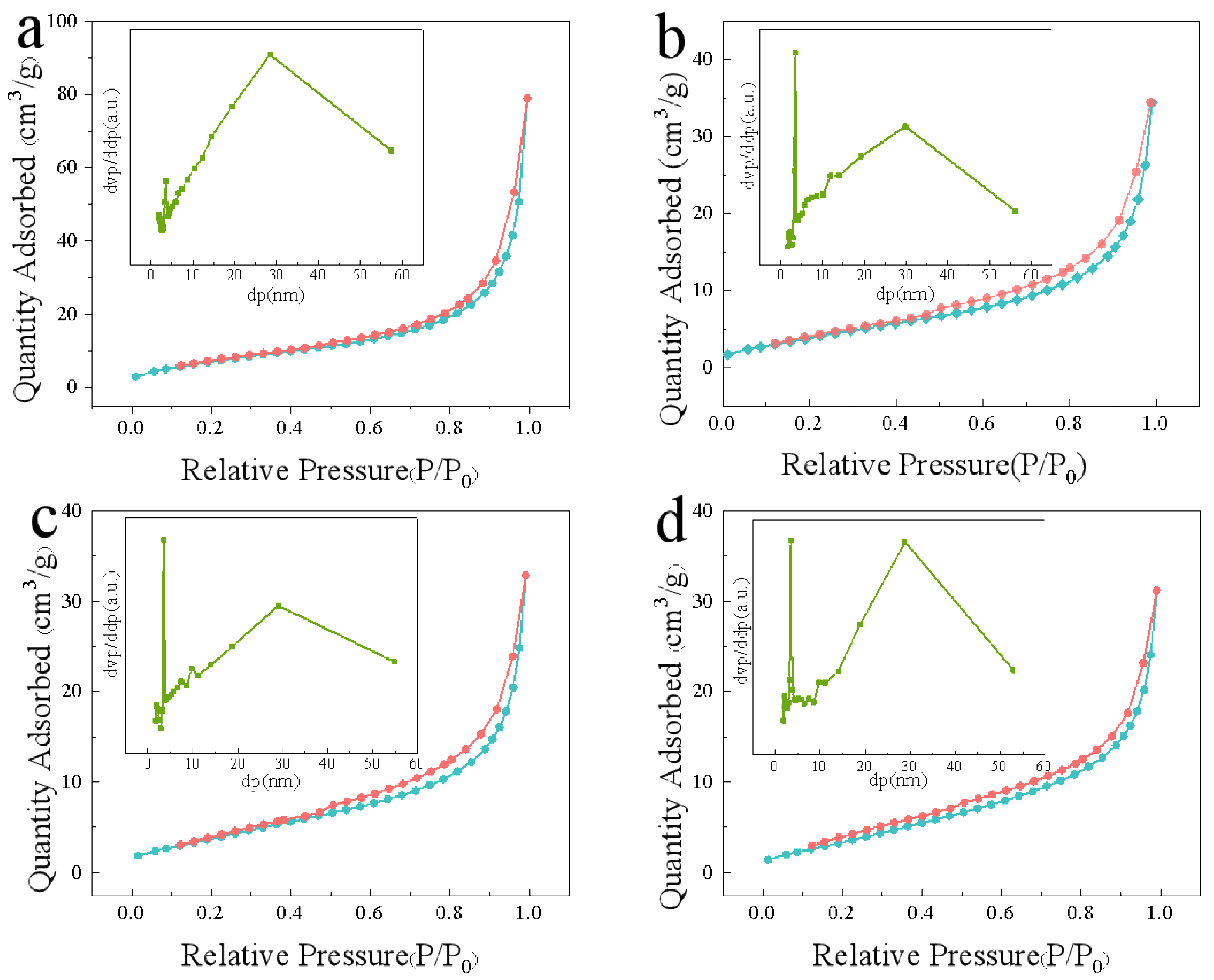
3.1. Morphology and Structure Characterization

The XRD characterization was carried out to explore the crystallinity of the synthesized samples. As shown in Figure 1a and Figure S1 (see Supplementary Materials), it was confirmed that the characteristic peaks of Ni-MOFs are completely consistent with the lamellar structure of [Ni3(OH)2(C8H4O4)2(H2O)4]·2H2O, and no obvious heteropeaks appear. In addition, the characteristic peaks of the samples remain highly consistent with Ni-MOF simulation after doping with different elements, indicating that both Ni-MOF and NiM-MOF materials were successfully synthesized [35]. It is noteworthy that the intensity of the derived peak changes with the introduction of Cu, which may be due to the preferred orientation of the crystal plane caused by the change of the internal atomic arrangement during the synthesis process [37]. The element composition and chemical states of the four products were deeply explored by XPS measurement. By comparing and observing the full-scan spectra of Ni-MOFs (Figure 1b), NiCo-MOFs (Figure 1e), NiMn-MOFs (Figure 1i), and NiCu-MOFs (Figure 1m), the successful doping of Co2+, Mn2+, and Cu2+ can be fully proved. In order to compare the changes of the several materials more clearly, high-resolution spectra of Co 2p (Figure 1f), Mn 2p (Figure 1j), and Cu 2p (Figure 1n) were further analyzed. Among them, the two characteristic peaks of the Co 2p spectrum at 781.03 eV (Co 2p3/2) and 797.14 eV (Co 2p1/2) correspond to the satellite peaks at 785.51 eV and 802.80 eV [38]. The high-resolution XPS spectrum of Mn 2p can be fitted to two characteristic peaks of 641.30 eV (Mn 2p3/2) and 653.16 eV (Mn 2p1/2) and two corresponding satellite peaks [39]. Similarly, two major components Cu 2p3/2 (934.57 eV) and Cu 2p1/2 (954.42 eV) can be observed in the Cu 2p spectra, as well as strong Cu 2p satellite peaks at 940.02 eV, 943.72 eV, 959.45 eV, and 963.09 eV [40]. Obviously, the analysis of high-resolution spectra more fully proves the existence of Co2+, Mn2+, and Cu2+ in the samples. In addition, the spectrum of Ni 2p of Ni-MOFs (Figure 1c), NiCo-MOFs (Figure 1g), NiMn-MOFs (Figure 1k), and NiCu-MOFs (Figure 1o) show almost the same diffraction peak positions, all showing two shake-up satellites and two characteristic peaks of Ni 2p3/2 (855.8 eV) and Ni 2p1/2 (873.7 eV), which can be assigned to the 2p orbits of Ni2+. Furthermore, the diffraction peaks at 284.5 eV (C-C), 285.0 eV (C-OH), and 288.5 eV (O=C-OH) are also presented in the C 1s spectrum (Figure 1d,h,p) [41,42].
The morphology and structural characteristics of the samples were explored by SEM (Figure 2a–d). It was observed in Figure 2a that the overall morphology of Ni-MOFs presented regular lamellar accumulation flower-like microspheres, and numerous large and small cavities were generated by the stacking of slim lamellar layers on the surface, which provided plentiful active sites in the electrochemical reaction process. After the introduction of other elements, the material still maintained the flower-like microsphere morphology, but the phenomenon of nanosheet enlargement occurred in NiM-MOFs, which may be because the introduction of other metal sources promoted the stacking of several small lamellae and finally formed a larger lamella. These larger lamellar layers form deeper and stronger pores, which not only ensure a large number of active sites, but also avoid self-agglomerations during electrochemical charge and discharge. Significantly, the lamellar density and thickness of NiCu-MOFs also changed greatly, which may be caused by the difference in the coordination ability of Ni2+ and Cu2+ in the synthesis environment, corresponding well with the XRD results. The element composition and distribution were further illustrated by EDS (Figure 2e–h). Specifically, Ni-MOFs are composed of Ni, O, and C, while in NiCo-MOFs, NiMn-MOFs, and NiCu-MOFs the presence of Co, Mn, and Cu was detected besides Ni, O, and C, respectively, proving the successful introduction of elements. At the same time, the metal ratio has also been well evaluated (Figure S2), which shows that the molar ratio of Ni:Co (Mn, Cu) in all materials is approximately consistent with the metal ratio added during the synthesis process. In addition, the element mapping images showed uniform distribution of all elements in the four samples, indicating the successful synthesis of bimetallic organic frameworks.
The BET characterization further explained the structure features of the samples from the perspective of pore structure and specific surface area (Figure 3). Four curves exhibit Type III isotherms, which indicates that the bimetallic MOFs prepared by this method retain the original basic structure. Meanwhile, the corresponding specific surface area was calculated through BJH, which slightly decreased after the introduction of other metal ions; the specific data are shown in Table S1. In addition, by comparing the pore structure of the four MOF materials, it was found that they all have pores at about 3.5 nm and 29 nm, which belong to mesopore. This unique pore structure maintains a sufficient contact area between electrolyte and active material, and effectively reduces self-aggregation of the structure during the electrochemical reaction [43]. However, unlike in Ni-MOFs, smaller mesoporous structures gradually increased after the introduction of other metal salts, which was more obvious in NiMn-MOFs and NiCo-MOFs. The increase of mesoporous structures may be attributed to the close stacking of lamellae, which is more beneficial to the smooth transmission of ions/electrons during the electrochemical process.

3.2. Electrochemical Performances

The energy storage capacity of the four samples were explored through CV, GCD, and EIS measurement. By observing the comparative CV curves of the four materials at a scanning speed of 5 mV·s−1 (Figure 4a), it was found that each curve has paired redox peaks, indicating its obvious pseudocapacitance characteristics. In addition, NiCo-MOFs have the largest integral area by comparison, proving that the doping of cobalt can effectively improve the electrochemical activity and energy storage capacity of MOFs, which may be closely connected with the synergistic effect of metal ions. Subsequently, CV curves of NiCo-MOFs (Figure 4b), Ni-MOFs (Figure S3a), NiMn-MOFs (Figure S3c), and NiCu-MOFs (Figure S3e) were obtained at 0–0.6 V. Each CV curve maintained a similar shape with the increase of scanning speed, which indicates that the samples have a faster electron/ion transfer rate and stronger reversibility. The excellent properties of the samples can be put down to the rapid and reversible redox reaction; the corresponding reaction process is as follows (where M represents the metals Ni, Co, Mn, and Cu) [37]:
M 3 ( O H ) 2 ( C 8 H 4 O 4 ) 2 ( H 2 O ) 4 · 2 H 2 O + O H _     M 3 O ( O H ) ( C 8 H 4 O 4 ) 2 ( H 2 O ) 4 · 2 H 2 O + H 2 O + e _ M 3 O ( O H ) ( C 8 H 4 O 4 ) 2 ( H 2 O ) 4 · 2 H 2 O + O H _     M 3 O 2 ( C 8 H 4 O 4 ) 2 ( H 2 O ) 4 · 2 H 2 O + H 2 O + e _
The electrochemical reaction kinetics of NiCo-MOFs have been reasonably evaluated by analyzing CV curves, mainly referring to the mathematical relationship between scanning speed and peak current (Figure 4c). The peak current is positively proportional to the square root of the scanning speed, which demonstrates the diffusion control characteristics of NiCo-MOFs and proves their battery-type energy storage mechanism [44]. Furthermore, EIS were tested to investigate the characteristics of rapid ion diffusion and effective electron transfer during the redox reaction (Figure 4d). In the low frequency region, the straight line represents the Warburg impedance resistance (Zw), which is closely related to the ion/electron transmission speed. The slope of the straight line of NiCo-MOFs is the largest compared with the other three materials, indicating that their ion transport resistance during the diffusion process is the smallest [45]. In the high frequency region, the diameter of the semicircle represents the faraday charge transfer resistance (Rct) related to electron transfer, and the electron transfer rate is inversely proportional to the diameter. Obviously, both the semicircular diameter and the linear slope of NiCo-MOFs show characteristics that are more conducive to the transfer of active materials of electrode materials, which fully explains the significant improvement in the performance of NiCo-MOFs.
To further explore the energy storage property of the samples, GCD curves were tested at 0.5, 1, 2, 5, and 10 A·g−1 during 0–0.5 V. Compared with Ni-MOFs (579 F·g−1), NiMn-MOFs (747 F·g−1), and NiCu-MOFs (345 F·g−1), NiCo-MOFs showed the highest specific capacity of 882 F·g−1 at 0.5 A·g−1. Unlike NiCu-MOFs, the introduction of Co2+ and Mn2+ has effectively improved the specific capacity. The improved charge storage capacity of NiCo-MOFs and NiMn-MOFs may be due to the relatively close physicochemical properties of Co2+, Mn2+, and Ni2+, such as solubility, ionic radius, etc., which make the nucleation rate and growth rate of Co2+ and Mn2+ relatively close to that of Ni2+ during hydrothermal reactions. The GCD curves of Ni-MOFs (Figure S3b), NiCo-MOFs (Figure 5b), NiMn-MOFs (Figure S3d), and NiCu-MOFs (Figure S3f) at different current densities were also obtained. Each curve of NiCo-MOF electrode material under different current densities shows two potential platforms, which further confirms the pseudocapacitance characteristics of the material. In addition, the symmetrical charge–discharge platform also proves the excellent reversibility of the reaction. After calculation, the specific capacitances of NiCo-MOFs are 882, 832, 788, 662, and 536 F·g−1 at 0.5, 1, 2, 5, and 10 A·g−1, which is significantly better than in Ni-MOFs (579, 493, 396, 340, and 302 F·g−1), NiMn-MOFs (747, 566, 472, 368, and 260 F·g−1), and NiCu-MOFs (345, 298, 263, 208, and 96 F·g−1).
The rate property of the four materials obtained by the GCD curve is shown in Figure 5c. The specific capacity of NiCo-MOFs still maintains a relatively high level even at 10 A·g−1, which can reach 60.84% of the initial value. For comparison, the capacitance retention of Ni-MOFs, NiMn-MOFs, and NiCu-MOFs were calculated to be 52.18%, 34.79%, and 27.83%, respectively, which more intuitively illustrates that the NiCo-MOF electrode material exhibited outstanding rate performance. Meanwhile, it can be found that the introduction of Mn2+ and Cu2+ is not conducive to maintaining charge storage capacity under high current density, which is a result of the conductivity reduction caused by the inherent properties of the elements and the mismatched coordination ability between metal ions. On this basis, the cycle life of the four electrode materials—Ni-MOFs, NiCu-MOFs, NiMn-MOFs, and NiCo-MOFs—was explored through the GCD results at 5 A·g−1 (Figure 5d). The results displayed that NiCo-MOFs exhibited optimal stability (90.1%) after 3000 cycles, which is an improvement to a certain extent over Ni-MOFs (85.0%). However, it is noteworthy that the introduction of Mn2+ (64.5%) and Cu2+ (27.8%) reduces the stability of the electrode material to varying degrees. The excellent cycle life of NiCo-MOF electrode materials may be ascribed to the unique pore structure formed by the sphere-shaped morphology of the stacked layers, which effectively inhibits the shrinkage and expansion of the active material during the cycle test, thereby increasing the utilization efficiency of the active material. Table S2 presents the electrochemical performance of NiCo-MOFs in this work compared with other literature.
In summary, differences in elemental composition lead to differences in deprotonation energy, which leads to differences in the difficulty of electrochemical reactions. Unlike NiMn-MOFs and NiCu-MOFs, the specific capacity, rate performance, and durability of NiCo-MOFs was more optimal compared to Ni-MOFs, which can be ascribed to the optimized conductivity and synergistic effect of Ni2+ and Co2+. Firstly, the similar physical and chemical nature of Ni2+ and Co2+ makes it exhibit better electrochemical activity, which is conducive to the storage of charge during the reaction. In addition, the unique pore structure formed by the spherical morphology of the laminated flowers has an active impact on the optimization of electrochemical performance. Additionally, the reduced internal resistance is also beneficial to the energy storage performance of electrode material, which could be confirmed through impedance spectroscopy. In addition, CV curves displayed that the oxidation peak of NiCo-MOFs is located on the lowest electrode potential (Figure 4a), which indicates that the lower potential is required due to the promoted ion migration. It is worth noting that compared with Ni-MOFs, NiMn-MOF electrode materials have improved specific capacitance, but their cycle stability and rate performance are reduced to a certain extent. Furthermore, the specific capacity, rate performance, and durability were greatly reduced after the introduction of Cu2+, which may be related to the difference in coordination ability between the two metals and the physicochemical properties of the metal itself.
Based on the excellent electrochemical performance of NiCo-MOFs, a hybrid supercapacitor was assembled with activated carbon to further explore its potential application (Figure 6a). AC showed typical double-layer capacitance characteristics during −1.1–0 V (104 F·g−1 at 1 A·g−1, Figure S4a,b). The CV curves of NiCo-MOFs (0–0.6 V) and AC (−1.1–0 V) at 10 mV·s−1 clearly indicate that the potential range of NiCo-MOFs//AC HSCs is about 0–1.7 V (Figure 6b). This conclusion can be further confirmed by the CV curves of NiCo-MOFs//AC HSCs in different voltage window ranges (Figure S4c). It can be seen that severe polarization occurs in the voltage window of 0–1.8 V, so further exploration should be performed within the voltage window of 0–1.6 V.
CV curves with quasi-rectangular shapes for NiCo-MOFs//AC HSCs were obtained at different scanning rates (Figure 6c), which not only proved their excellent charge storage performance, but also indicated the combined effect of faraday pseudocapacitance and double-layer capacitance. Figure 6d displays the GCD curves of NiCo-MOFs//AC HSCs at 0.5, 1, 2, 5, and 10 A·g−1, with corresponding specific capacities of 52, 42, 38, 34, and 30 F·g−1, respectively. In addition, NiCo-LDH-1M//AC HSCs exhibit an outstanding rate property through the good symmetry of the GCD curve (Figure S4d). The durability was evaluated by cyclic charging and discharging 3000 times at 5 A·g−1 (Figure 6e). The specific capacity maintained 82.4% of the initial value, proving its excellent cycle durability and application potential. The energy/power density were investigated by Ragone diagram (Figure 6f). After calculations, the energy density was as high as 18.33 Wh·kg−1 at 400 W·kg−1, and 12.44 Wh·kg−1, even at 4000 W·kg−1. In addition, connecting two prepared HSCs in series can light up the green, red, and yellow LEDs and keep them on for 30 min (the illustration in Figure 6f), demonstrating the possibility of practical application of the device.

4. Conclusions

In short, a series of flower-like nickel-based bimetallic MOF microspheres with similar structures were synthesized by introducing different metal ions into Ni-MOFs using a simple and gentle solvothermal method. Electrochemical measurements show that Co2+ and Mn2+ can promote the energy storage capacity of MOF electrode materials. At 0.5 A·g−1, the specific capacity increased to 882 F·g−1 and 747 F·g−1, respectively. Unlike NiMn-MOFs, NiCo-MOFs can maintain excellent stability and rate (the capacitance retention rate can reach 90.1% after 3000 cycles at 5 A·g−1). Moreover, the HSCs made by assembling NiCo-MOFs and AC also exhibited satisfactory energy density (18.33 Wh·kg−1 at a power density of 400 W·kg−1) and durability (82.4% after 3000 cycles). Different element compositions lead to differences in deprotonation energy, which lead to different degrees of difficulty in electrochemical reactions, which may be the main reason for differences in electrochemical performance. This research provides a general method for the application of MOFs in the field of supercapacitors.

Supplementary Materials

The following are available online at https://0-www-mdpi-com.brum.beds.ac.uk/article/10.3390/cryst11111425/s1: Figure S1: The XRD spectra of Ni-MOFs and Ni-MOFs simulation (CCDC No.638866); Figure S2: The EDS spectra of (a) Ni−MOFs, (b) NiCo−MOFs, (c) NiMn−MOFs and (d) NiCu−MOFs; Figure S3: CV curves of (a) Ni−MOFs; (c) NiMn−MOFs and (e) NiCu−MOFs at scan rates of 1~20 mV·s−1; GCD curves of (b) Ni−MOFs, (d) NiMn−MOFs and (f) NiCu−MOFs at different current densities; Figure S4: (a) CV and (b) GCD curves of AC measured in the 2M KOH; (c) CV curves of the NiCo−MOFs//AC HSCs tested at a scan rate of 50 mV·s−1 with different voltage windows; (d) rate performance of the NiCo−MOFs//AC HSCs; Table S1: Specific surface area of the four synthesized samples; Table S2: Comparison of electrochemical performance between the NiCo−MOFs and previous reports.

Author Contributions

Formal analysis, M.L.; methodology, M.L., G.W. and X.X.; data curation, D.J.; supervision, C.W. and Z.Z.; writing—original draft preparation, D.J.; writing—review and editing, M.L., X.X. and G.W. All authors have read and agreed to the published version of the manuscript.

Funding

This project is financially supported by the National Natural Science Foundation of China (51972049 and 52073010), the Projects of the Science and Technology Department of Jilin Province (20190303025SF).

Institutional Review Board Statement

Not applicable.

Informed Consent Statement

Not applicable.

Data Availability Statement

The data presented in this study are available on request from the corresponding author.

Conflicts of Interest

The authors declare no conflict of interest.

References

  1. Lee, D.Y.; Yoon, S.J.; Shrestha, N.K.; Lee, S.; Ahn, H.; Han, S. Unusual Energy Storage and Charge Retention in Co-based Metal-Organic-Frameworks. Microporous Mesoporous Mater. 2012, 153, 163–165. [Google Scholar] [CrossRef]
  2. Elsayed, A.; Elsayed, E.; Al-Dadah, R.; Mahmoud, S.; Elshaer, A.; Kaialy, W. Thermal Energy Storage Using Metal-Organic Framework Materials. Appl. Energy 2017, 186, 509–519. [Google Scholar] [CrossRef] [Green Version]
  3. Andikaey, Z.; Ensafi, A.A.; Rezaei, B. Synthesis of Engineered Graphene Nanocomposites Coated with NiCo Metal-organic frameworks as Electrodes for High-quality Supercapacitor-ScienceDirect. Int. J. Hydrog. Energy 2020, 45, 32059–32071. [Google Scholar] [CrossRef]
  4. Li, J.; Hou, L.F.; Yan, Z.; Sun, H. The Influence of Preload on the Performance of Lithium-air Battery. J. Northeast Electr. Power Univ. 2021, 1, 41–47. [Google Scholar]
  5. Hulicova-Jurcakova, D.; Seredych, M.; Lu, G.Q.; Bandosz, T.J. Combined Effect of Nitrogen-and Oxygen-Containing Functional Groups of Microporous Activated Carbon on its Electrochemical Performance in Supercapacitors. Adv. Funct. Mater. 2010, 19, 438–447. [Google Scholar] [CrossRef]
  6. Liu, W.; Yin, X.B. Metal-Organic Frameworks for Electrochemical Applications. TrAC Trends Anal. Chem. 2016, 75, 86–96. [Google Scholar] [CrossRef]
  7. Vivekchand, S.R.C.; Rout, C.S.K.; Subrahmanyam, S. Graphene-based Electrochemical Supercapacitors. J. Chem. Sci. 2008, 120, 9–13. [Google Scholar] [CrossRef]
  8. Yu, X.; Yun, S.; Yeon, J.S.; Bhattacharya, P.; Wang, L.B.; Lee, S.W.; Hu, X.L.; Park, H.S. Pseudocapacitance: Emergent Pseudocapacitance of 2D Nanomaterials. Adv. Energy Mater. 2018, 8, 1702930–1702963. [Google Scholar] [CrossRef]
  9. Nakhanivej, P.; Yu, X.; Park, S.K.; Kim, S.; Hong, J.Y.; Kim, H.J. Revealing Molecular-level Surface Redox Sites of Controllably Oxidized Black Phosphorus Nanosheets. Nat. Mater. 2019, 18, 156–162. [Google Scholar] [CrossRef]
  10. Wang, G.S.; Lu, M.; Yuan, X.P.; Guan, X.H. Synthesis of Nickel Chalcogenide Hollow Spheres Using an L-Cysteine-Assisted Hydrothermal Process for Efficient Supercapacitor Electrodes. J. Mater. Chem. A 2017, 5, 3621–3627. [Google Scholar]
  11. Jiang, D.; Wei, C.Y.; Zhu, Z.Y.; Guan, X.H.; Lu, M.; Wang, G.S. Synthesis of 3D Flower-like Hierarchical NiCo-LDH Microspheres with Boosted Electrochemical Performance for Hybrid Supercapacitors. Inorg. Chem. Front. 2021, 8, 4324–4333. [Google Scholar] [CrossRef]
  12. Furukawa, H.; Cordova, K.E.; Keeffe, M.O.; Yaghi, O.M. ChemInform Abstract: The Chemistry and Applications of Metal-Organic Frameworks. Science 2013, 341, 1230444. [Google Scholar] [CrossRef] [PubMed] [Green Version]
  13. Xu, B.; Zhang, H.; Mei, H.; Sun, D.F. Recent Progress in Metal-Organic Framework-based Supercapacitor Electrode Materials. Coordin. Chem. Rev. 2020, 420, 213438. [Google Scholar]
  14. Jiao, Y.; Chen, G.; Chen, D.; Pei, J.; Hu, Y. Bimetal-Organic Framework Assisted Polymerization of Pyrrole Involving Air Oxidant to Prepare Composite Electrodes for Portable Energy Storage. J. Mater. Chem. A 2017, 5, 23744–23752. [Google Scholar] [CrossRef]
  15. Zhou, Y.; Mao, Z.; Wang, W.; Yang, Z.; Liu, X. In-situ Fabrication of Graphene Oxide Hybrid Ni-based Metal-Organic Framework (Ni-MOFs@GO) with Ultrahigh Capacitance as Electrochemical Pseudocapacitor Materials. ACS Appl. Mater. Interf. 2016, 8, 28904–28916. [Google Scholar] [CrossRef] [PubMed]
  16. Jiao, Y.; Pei, J.; Yan, C.; Chen, D.; Hu, Y.; Chen, G. Layered Nickel Metal-Organic Framework for High Performance Alkaline Battery-Supercapacitor Hybrid Devices. J. Mater. Chem. A 2016, 4, 13344–13351. [Google Scholar] [CrossRef]
  17. Jasuja, H.; Jiao, Y.; Burtch, N.C.; Huang, Y.; Walton, K.S. Synthesis of Cobalt-, Nickel-, Copper-, and Zinc-based, Water-stable, Pillared Metal-Organic Frameworks. Langmuir 2014, 30, 14300–14307. [Google Scholar] [CrossRef] [PubMed]
  18. Campagnol, N.; Romero-Vara, R.; Deleu, W.; Stappers, L.; Binnemans, K.; DeVos, D.E.; Fransaer, J. A Hybrid Supercapacitor based on Porous Carbon and the Metal-Organic Framework MIL-100(Fe). ChemElectroChem 2014, 1, 1182–1188. [Google Scholar] [CrossRef]
  19. Lee, D.Y.; Shinde, D.V.; Kim, E.K.; Lee, W.; Oh, I.W.; Shrestha, N.K.; Lee, J.K.; Han, S.H. Supercapacitive Property of Metal-Organic-Frameworks with Different Pore Dimensions and Morphology. Microporous Mesoporous Mater. 2013, 171, 53–57. [Google Scholar] [CrossRef]
  20. Gong, Y.; Li, J.; Jiang, P.G.; Li, Q.F.; Lin, J.H. Novel Metal(II) Coordination Polymers Based on N,N’-bis-(4-pyridyl)phthalamide as Supercapacitor Electrode Materials in an Aqueous Electrolyte. Dalton Trans. 2013, 42, 1603–1611. [Google Scholar] [CrossRef]
  21. Choi, K.M.; Jeong, H.M.; Park, J.H.; Zhang, Y.B.; Kang, J.K.; Yaghi, O.M. Supercapacitors of Nanocrystalline Metal-Organic Frameworks. ACS Nano 2014, 8, 7451–7457. [Google Scholar] [CrossRef]
  22. Du, M.; Chen, M.; Yang, X.G.; Wen, J.; Wang, X.; Fang, S.M.; Liu, C.S. A Channel-type Mesoporous In(iii)-Carboxylate Coordination Framework with High Physicochemical Stability for Use as an Electrode Material in Supercapacitors. J. Mater. Chem. A 2014, 2, 9828–9834. [Google Scholar] [CrossRef]
  23. Yu, Z.; Tetard, L.; Zhai, L.; Thomas, J. Supercapacitor Electrode Materials: Nanostructures from 0 to 3 Dimensions. Energy Environ. Sci. 2015, 8, 702–730. [Google Scholar] [CrossRef] [Green Version]
  24. He, X.; Liu, Q.; Liu, J.; Li, R.; Zhang, H.; Chen, R.; Wang, J. High-Performance All-Solid-State Asymmetrical Supercapacitors Based on Petal-like NiCo2S4/Polyaniline nanosheets. Chem. Eng. J. 2017, 325, 134–143. [Google Scholar] [CrossRef]
  25. Sheberla, D.; Bachman, J.C.; Elias, J.S.; Sun, C.J.; Shao-Horn, Y. Conductive MOF Electrodes for Stable Supercapacitors with High Areal Capacitance. Nat. Mater. 2017, 16, 220–224. [Google Scholar] [CrossRef]
  26. Gao, S.; Sui, Y.; Wei, F.; Qi, J.; He, Y. Facile Synthesis of Cuboid Ni-MOF for High-Performance Supercapacitors. J. Mater. Sci. 2018, 53, 6807–6818. [Google Scholar] [CrossRef]
  27. Yan, Y.; Gu, P.; Zheng, S.S.; Zheng, M.B.; Pang, H.; Xue, H.G. Facile Synthesis of an Accordion-like Ni-MOF Superstructure for High-Performance Flexible Supercapacitors. J. Mater. Chem. A 2016, 4, 19078–19085. [Google Scholar] [CrossRef]
  28. Kang, L.; Sun, S.X.; Kong, L.B.; Lang, J.W.; Luo, Y.C. Investigating Metal-Organic Framework as a New Pseudo-Capacitive Material for Supercapacitors. Chin. Chem. Lett. 2014, 25, 957–961. [Google Scholar] [CrossRef]
  29. Qu, C.; Jiao, Y.; Zhao, B.; Chen, D.; Zou, R.; Walton, K.S.; Liu, M. Nickel-based Pillared MOFs for High-Performance Supercapacitors: Design, Synthesis and Stability Study. Nano Energy 2016, 26, 66–73. [Google Scholar] [CrossRef] [Green Version]
  30. Xu, J.; Yang, C.; Xue, Y.; Wang, C.; Cao, J.; Chen, Z. Facile Synthesis of Novel Metal-Organic Nickel Hydroxide Nanorods for High Performance Supercapacitor. Electrochim. Acta 2016, 211, 595–602. [Google Scholar] [CrossRef]
  31. Ren, F.; Ji, Y.; Chen, F.; Qian, Y.; Tian, J.; Wang, J. Flower-like Bimetal Ni/Co-based Metal-organic-framework Materials with Adjustable Components toward High Performance Solid-state Supercapacitors. Mater. Chem. Front. 2021, 5, 7333–7342. [Google Scholar] [CrossRef]
  32. Wang, J.; Zhong, Q.; Zeng, Y.; Cheng, D.; Xiong, Y.; Bu, Y. Rational Construction of Triangle-like Nickel-cobalt Bimetallic Metal-Organic Framework Nanosheets Arrays as Battery-type Electrodes for Hybrid Supercapacitors. J. Colloid Interf. Sci. 2019, 555, 42–52. [Google Scholar] [CrossRef]
  33. Gholipour-Ranjbar, H.; Soleimani, M.; Naderi, H.R. Application of Ni/Co-based Metal-Organic Frameworks (MOFs) as an Advanced Electrode Material for Supercapacitors. New J. Chem. 2016, 40, 9187–9193. [Google Scholar] [CrossRef]
  34. Díaz, R.; Orcajo, M.G.; Botas, J.A.; Calleja, G.; Palma, J. Co8-MOF-5 as Electrode for Supercapacitors. Mater. Lett. 2012, 68, 126–128. [Google Scholar] [CrossRef]
  35. Li, G.C.; Liu, P.F.; Liu, R.; Liu, M.; Tao, K.; Zhu, S.R.; Wu, M.K.; Yi, F.Y.; Han, L. MOF-derived Hierarchical Double-shelled NiO/ZnO Hollow Spheres for High-Performance Supercapacitors. Dalton Trans. 2016, 45, 13311–13316. [Google Scholar] [CrossRef] [PubMed]
  36. Yang, J.; Xiong, P.; Zheng, C.; Qiu, H.; Wei, M. Metal-Organic Frameworks: A New Promising Class of Materials for A High Performance Supercapacitor Electrode. J. Mater. Chem. A 2014, 2, 16640–16644. [Google Scholar] [CrossRef]
  37. Yang, J.; Zheng, C.; Xiong, P.; Li, Y.; Wei, M. Zn-doped Ni-MOF Material with a High Supercapacitive Performance. J. Mater. Chem. A 2014, 2, 19005–19010. [Google Scholar] [CrossRef]
  38. Mei, H.; Mei, Y.; Zhang, S.; Xiao, Z.; Xu, B.; Zhang, H.; Fan, L.; Huang, Z.D.; Kang, W.P.; Sun, D.F. Bimetallic-MOF Derived Accordion-like Ternary Composite for High-Performance Supercapacitors. Inorg. Chem. 2018, 57, 10953–10960. [Google Scholar] [CrossRef]
  39. Tang, Y.Q.; Shen, H.M.; Cheng, J.Q.; Liang, Z.B.; Qu, C.; Tabassum, H.; Zou, R.Q. A Universal Strategy for Hollow Metal Oxide Nanoparticles Encapsulated into B/N Co-Doped Graphitic Nanotubes as High-Performance Lithium-Ion Battery Anodes. Adv. Funct. Mater. 2020, 30, 1908223–1908231. [Google Scholar] [CrossRef]
  40. Mohamed, H.S.H.; Wu, L.; Li, C.F.; Hu, Z.Y.; Liu, J.; Deng, Z.; Chen, L.H.; Li, Y.; Su, B.L. In-Situ Growing Mesoporous CuO/O-Doped g-C3N4 Nanospheres for Highly Enhanced Lithium Storage. ACS Appl. Mater. Interf. 2019, 11, 32957–32968. [Google Scholar] [CrossRef] [PubMed]
  41. Zhang, H.B.; Xu, B.; Mei, H.; Mei, Y.J.; Zhang, S.Y.; Yang, Z.D.; Xiao, Z.Y.; Kang, W.P.; Sun, D.F. „HOT” Alkaline Hydrolysis of Amorphous MOF Microspheres to Produce Ultrastable Bimetal Hydroxide Electrode with Boosted Cycling Stability. Small 2019, 15, 1904663. [Google Scholar] [CrossRef] [PubMed]
  42. Yang, D.; Velamakanni, A.; Bozoklu, G.; Park, S.; Stoller, M.; Piner, R.D.; Stankovich, S.; Jung, I.; Field, D.A.; Ventrice, C.A. Chemical Analysis of Graphene Oxide Films after Heat and Chemical Treatments by X-ray Photoelectron and Micro-Raman Spectroscopy. Carbon 2009, 47, 145–152. [Google Scholar] [CrossRef]
  43. Qu, C.; Zhang, L.; Meng, W.; Liang, Z.B.; Zhu, B.J.; Dang, D.; Huang, Y.; Liu, M.L.; Zou, R.Q. MOF-derived α-NiS Nanorods on Graphene as an Electrode for High-Energy-Density Supercapacitors. J. Mater. Chem. A 2018, 6, 4003–4012. [Google Scholar] [CrossRef]
  44. Wang, Q.; Gao, F.; Xu, B.; Cai, F.; Zhan, F.; Gao, F.; Wang, Q. ZIF-67 Derived Amorphous CoNi2S4 Nanocages with Nanosheet Arrays on the Shell for a High-Performance Asymmetric Supercapacitor. Chem. Eng. J. 2017, 327, 387–396. [Google Scholar] [CrossRef]
  45. Ramachandran, R.; Saranya, M.; Velmurugan, V.; Ragupathy, B.P.C.; Jeong, S.K.; Grace, A.N. Effect of Reducing Agent on Graphene Synthesis and Its Influence on Charge Storage Towards Supercapacitor Applications. Appl. Energy 2015, 153, 22–31. [Google Scholar] [CrossRef]
Scheme 1. Schematic diagram of the synthesis process of Ni-MOFs and NiM-MOFs.
Crystals 11 01425 sch001
Figure 1. (a) XRD patterns of Ni-MOFs, NiCo-MOFs, NiMn-MOFs, and NiCu-MOFs; XPS spectra of (bd) Ni-MOFs, (eh) NiCo-MOFs, (il) NiMn-MOFs, and (mp) NiCu-MOFs.
Crystals 11 01425 g001aCrystals 11 01425 g001b
Figure 2. The SEM images of (a) Ni-MOFs, (b) NiCo-MOFs, (c) NiMn-MOFs, and (d) NiCu-MOFs; EDS elemental mapping images of (e) Ni-MOFs, (f) NiCo-MOFs, (g) NiMn-MOFs, and (h) NiCu-MOFs.
Crystals 11 01425 g002
Figure 3. N2 adsorption/desorption isotherms of (a) Ni-MOFs, (b) NiCo-MOFs, (c) NiMn-MOFs, and (d) NiCu-MOF. Pore size distribution is shown in the embedded diagram.
Crystals 11 01425 g003
Figure 4. (a) CV curves of four samples at 5 mV·s−1; (b) CV curves of NiCo−MOFs at 1–20 mV·s−1; (c) plots of the peak currents and the scan rates of NiCo−MOFs; (d) Nyquist plots of four samples; the equivalent circuit is shown in the embedded diagram.
Crystals 11 01425 g004
Figure 5. (a) GCD curves of four samples tested at 0.5 A·g−1; (b) GCD curves of NiCo−MOFs at different current densities; (c) specific capacitance at different current densities for four samples; (d) cycling stability performance of four samples at 5 A·g−1.
Crystals 11 01425 g005
Figure 6. (a) Setting diagram of the NiCo−MOFs//AC HSCs; (b) CV curves of the NiCo−MOFs and AC at 10 mV·s−1; (c) CV curves of NiCo−MOFs//AC HSCs at 5−80 mV·s−1; (d) GCD curves of NiCo−MOFs//AC HSCs at 0.5−10 A·g−1; (e) Cycling life of the NiCo−MOFs//AC HSCs at 5 A·g−1; (f) Ragone plot of the NiCo−MOFs//AC HSCs and the lit LEDs was shown in the embedded diagram.
Crystals 11 01425 g006
Publisher’s Note: MDPI stays neutral with regard to jurisdictional claims in published maps and institutional affiliations.

