Article

Microstructure and Mechanical Properties of Vacuum Diffusion Bonded Zr-4 Alloy Joint

1
Nuclear Fuel & Material Sub-Institute, Nuclear Power Institute of China, Chengdu 610213, China
2
Tianjin Key Laboratory of Advanced Joining Technology, School of Materials Science and Engineering, Tianjin University, Tianjin 300350, China
*
Author to whom correspondence should be addressed.
Submission received: 29 October 2021 / Revised: 14 November 2021 / Accepted: 19 November 2021 / Published: 22 November 2021

Abstract

:
The development of welding technology for zirconium alloy has great significance on the safety, stability, and reliability of the operation of the nuclear reactor. In this work, vacuum diffusion bonding of Zr-4 alloy was studied at the diffusion temperature ranging from 760 to 820 °C with holding times of 30–90 min. The effects of diffusion bonding temperature and holding time on the interfacial microstructure and mechanical properties of the diffusion bonded Zr-4 alloy joints were investigated in detail, and the relationship between the interfacial microstructure and shear strength of the diffusion bonded joints was discussed. The results show that the interface bonding ratio of the diffusion bonded Zr-4 joint gradually increased from 74% to 95% with the increasing of bonding temperature. In addition, the grain size of the base material became a larger and brittle second phase composed of Zr(Cr, Fe)2 and eutectic α-Zr + Zr(Fe, Cr)2 formed in the joint with the increase of the temperature as well as the extension of the bonding time. The highest shear strength of 349 MPa was obtained at 800 °C for 30 min under 7 MPa, and the crack of the joint was primarily propagated along with the base material rather than the bonded interface.

1. Introduction

To meet the growing demand for nuclear energy [1,2,3], the development of nuclear energy equipment has become particularly important [4,5,6,7]. Zirconium (Zr) and its alloys are primarily used as the fuel cladding in nuclear reactors and the structural materials of water reactors due to their low thermal neutron absorption cross-section, high corrosion resistance, and moderate mechanical properties [8,9,10,11]. Therefore, the development of a reliable technique to join Zr alloys is indispensable to its engineering applications. To date, many scientists have focused on zirconium alloy welding technology, which includes vacuum electron beam welding (EBW), tungsten inert gas welding (TIG), pulsed laser welding (LBW), and pressure resistance welding (RPW) [12,13,14,15,16]. J.G. Lee [13] and M.K. Lee et al. [14] have brazed Zr-4 alloy with multi-component alloy at high temperatures of 920 °C and 890 °C, respectively. However, the high brazing temperature tends to make large welding deformation. As a result, it is difficult to control the accuracy of the internal flow channel size of the component. Moreover, the long-period crevice corrosion tendency of the brazed Zr-4 alloy joint would be increased owing to the incomplete penetration structure [17]. Additionally, the metallurgical transformation is facile to occur in the heat-affected zones, resulting in the formation of intermetallic compounds and the reduced performance of joints [16,18]. The EBW [12] and TIG [15] methods are successfully employed to weld Zr-4 alloy and stainless steel, but the molten and heat-affected zones have an irreversible negative impact on the mechanical performance of the internal fuel core [19]. In the integrated manufacturing of new fuel elements with multi-layer densely joined structures [20,21,22], the spacing between welding joints is small and the welding joints are overlapped and influence each other. Considering the larger structural size of the fuel element, higher requirements for penetration control accuracy, and greater difficulty in deformation control, the use of traditional fusion welding methods for integrated manufacturing can no longer effectively meet the existing needs, and the above technical problems will be more prominent and lead to major challenges to the subsequent development of new fuel elements. Under this circumstance, it is urgent to develop a new welding method and process to meet this coming challenge.
With the development of emerging joining technologies, the diffusion bonding technology using micro-interface solid-phase joining [23,24] as a precision joining method is very suitable for rapid prototyping and integrated manufacturing of a large number of densely welded multi-layer superimposed components. To effectively decrease the adverse effects on the structure and performance of components after heating and reduce the difficulty of controlling the deformation size of the overall structure of precision components at the same time, the low-temperature diffusion bonding technology of zirconium alloys has got greater emphasis. Taouinet et al. [25,26] have directly bonded Zr-4 alloy to 304 L stainless steel at 1050 °C, and the typical interfacial microstructure was divided into three characteristic zones including reaction phases of α-Zr, α-(FeCr), Zr(Fe, Cr)2, and Zr2 (Fe, Ni). The diffusion zone at the bonded joint has a large thickness value of 700 μm, which is conducive to buffering the difference of mechanical properties between the two materials and improving the bonding performance of the joint. Additionally, the Ni and Ta as the hybrid interlayer, which was employed to prevent the formation of brittle Zr(Fe, Cr)2 and Zr2 (Fe, Ni), was also used to bond Zr-4 alloy to 304 L stainless steel at 850–1000 °C [16]. The shear strength of the bonded joint first increases and then decreases with the increase of the bonding temperature, and the maximum shear strength of 194 MPa was obtained at 950 °C. Until now, there are few studies on the diffusion bonding of zirconium alloy itself, so the microstructure and properties of the self-diffusion bonded joints of zirconium alloys still need further study.
In this work, the microstructures and properties of zirconium alloy after vacuum heat treatment at different temperatures were studied to preliminarily determine the bonding temperature range. The vacuum diffusion bonding of Zr-4 alloy without interlayer was carried out at a range of bonding parameters. The effect of diffusion temperature and holding time on the microstructure and mechanical properties of the diffusion bonded joints was investigated. Therefore, it is possible to explore the best process parameters of the diffusion bonding of zirconium alloy, which can provide the provision of technical reserves and process support for the precise diffusion bonding of new fuel elements.

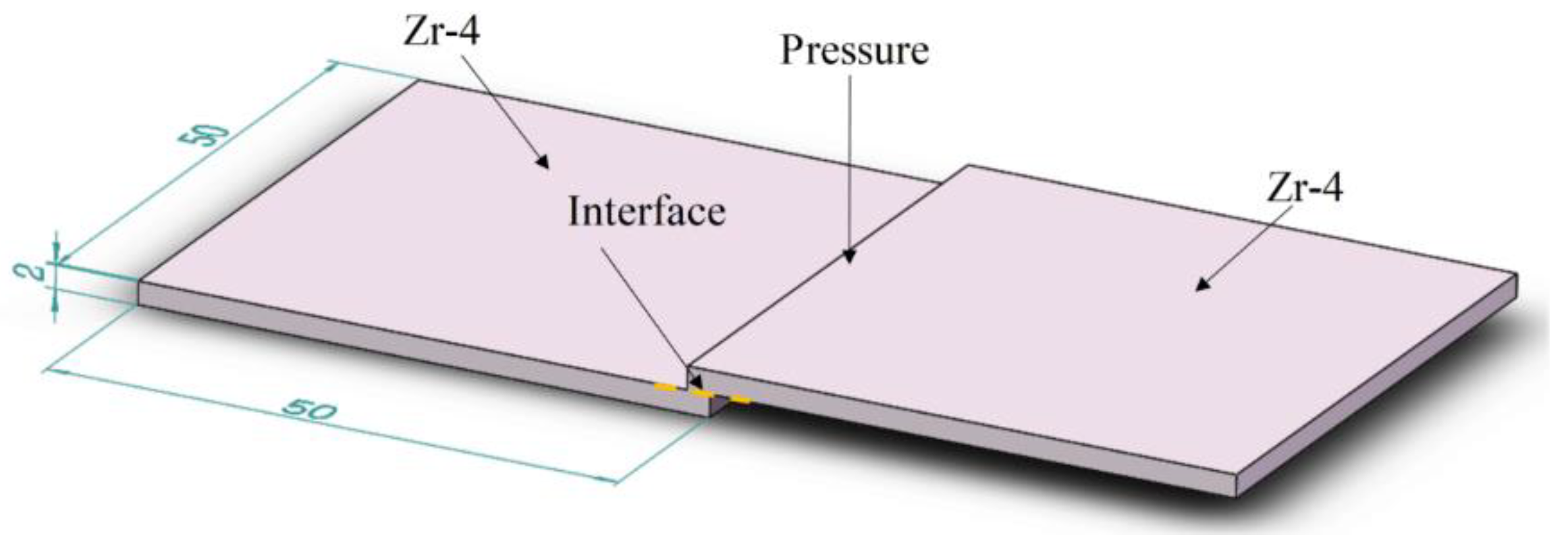
2. Materials and Experimental Procedures

Commercially, Zr-4 alloy (containing 1.5 wt.% Sn, 0.2 wt.% Fe, and 0.1 wt.% Cr) is used as the base material in this study. It is well accepted that the high temperature is conducive to increasing the interface bonding rate of diffusion bonded joint, while it is harmful to the mechanical properties of Zr-4 alloy due to the crystal grain coarsening. Therefore, it is urgent to find a balance between the interface bonding rate and the grain coarsening of the base material. To measure the degree of grain coarsening during vacuum diffusion bonding, the vacuum heat treatment experiment of Zr-4 alloy was firstly carried out to simulate the diffusion bonding process and explore the effects of temperature on the morphology and performance of the Zr-4 alloy.
To prepare the sample for the vacuum heat treatment experiment, the zirconium alloy was cut into a block of 70 × 30 × 2 mm3 by a wire-cut electric discharge machine, and then it was polished and ultrasonicated in acetone for 15 min to remove surface impurities and greases. The processed base material was finally put into a vacuum furnace with a degree less than 1 × 10⁻³ Pa. As for the heating process, the sample was heated to the target temperature with a heating rate of 10 °C/min, and the temperature is decreased to 400 °C with a cooling rate of 5 °C/min after the thermostatic process. Then, the furnace is cooled to room temperature and the sample was taken out for subsequent characterization. The zirconium alloy with the dimension of 50 × 50 × 2 mm3 was polished and ultrasonicated in acetone for vacuum diffusion bonding. The diffusion bonding assembly is assembled in the form of overlap, and the overlap length is 2 mm (Figure 1). The heat cycle of diffusion bonding is the same as that of the previous heat treatment, and the applied pressure is 7 MPa.
The heat-treated and diffusion-bonded samples for microstructure observation were cut by a wire-cut electric discharge machine. The cross-section of the sample was taken from the center of the diffusion bonded joint. The surface of the cross-section was polished and then etched by HF (15%)-HNO3 (45%)-H2O (40%) solution for 65 s. Scanning electron microscope (SEM, JSM-7800F) combined with an energy dispersive spectrometer (EDS) was used to characterize the microstructure and fracture morphology of the prepared samples. In addition, X-ray diffractometer (XRD, D8-ADVANCED) was used to detect the phase structure of base material and fracture surface of the joint. The shear test was completed by the MTS E45.105 electronic universal testing machine, and the indenter moving speed of the testing machine was 0.02 mm/s.

3. Results and Discussion

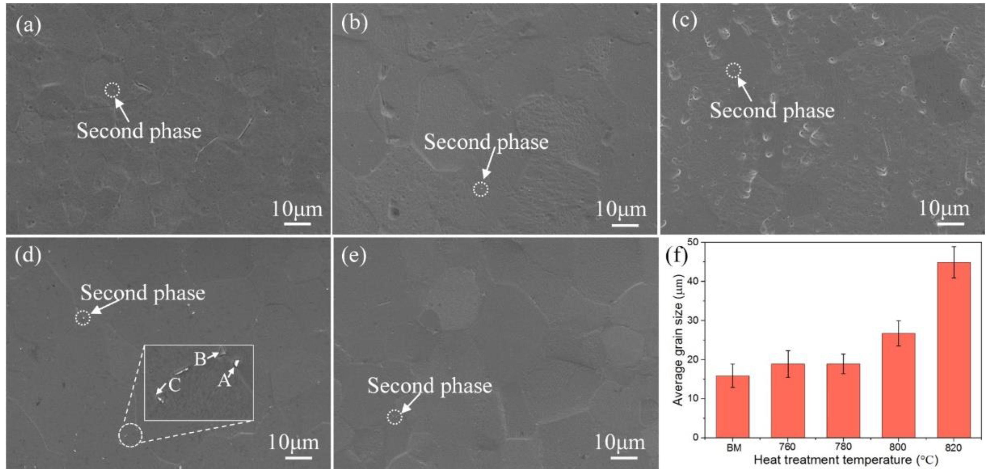
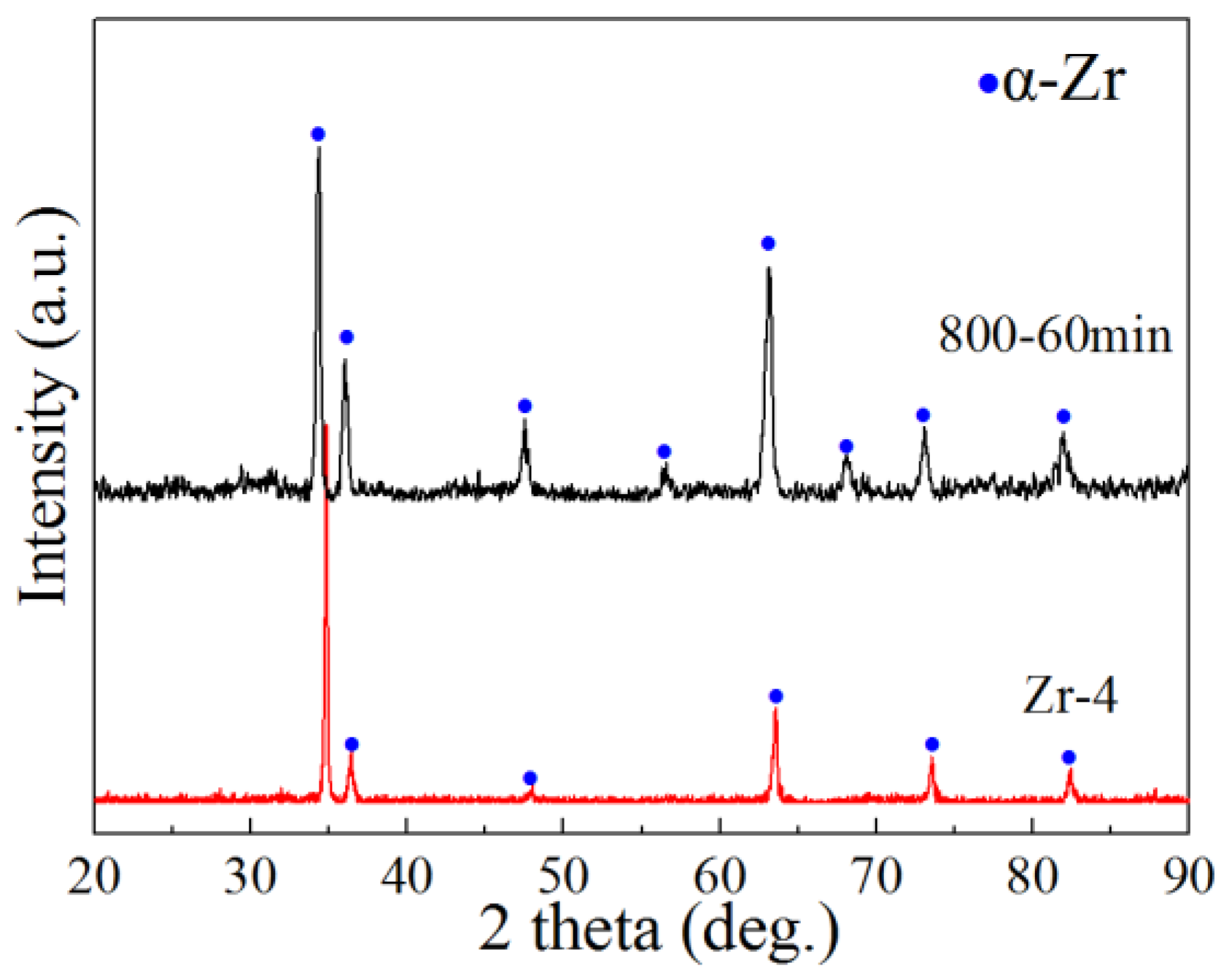
3.1. Effect of Heat Treatment on the Microstructure and Properties of Zr-4 Alloy

Figure 2 shows the microstructure of Zr-4 alloy under different heat treatment temperatures with a holding time of 60 min. Clearly, the grain size gradually increases with the increase of the heat treatment temperature. Meanwhile, the second phase with white color is precipitated in the matrix phase as observed in Figure 2, and its quantity and size increase with the increase of the heat treatment temperature. The chemical composition of the second phase is listed in Table 1 and the possible phase should be Zr(Cr, Fe)2 as reported in [25,26]. Furthermore, the second phase tends to scatter and distribute at the grain boundary and intragranular as the bonding temperature reaches 780 and 800 °C, while it is mainly distributed at the grain boundary as the temperature reaches 820 °C. The reasons for this change can be explained by the increase of the diffusion distance of Cr atoms in the Zr-4 alloy and the gradual segregation of elements to the grain boundary as the temperature rises.
To further determine the effect of heat treatment on the Zr-4 alloy, the grain size was calculated and the results are shown in Figure 2f. The grain size did not change significantly after heat treatment at 760 and 780 °C, and the grain size increased significantly to about 44.9 μm after heat treatment at 820 °C. It is widely accepted that the grain size of alloy will increase with the increase of heat treatment temperature, which will lead to a decrease in strength. In the temperature range of 760 to 820 °C, the Zr-4 alloy base material still retains high strength of 385.3 MPa after thermal cycling, which is slightly lower than that of the base material (389 MPa). Furthermore, the crystal grains are not severely coarsened. Therefore, it is reasonable to set the diffusion bonding temperature in the range of 760 to 820 °C for diffusion bonding of Zr-4 alloy.

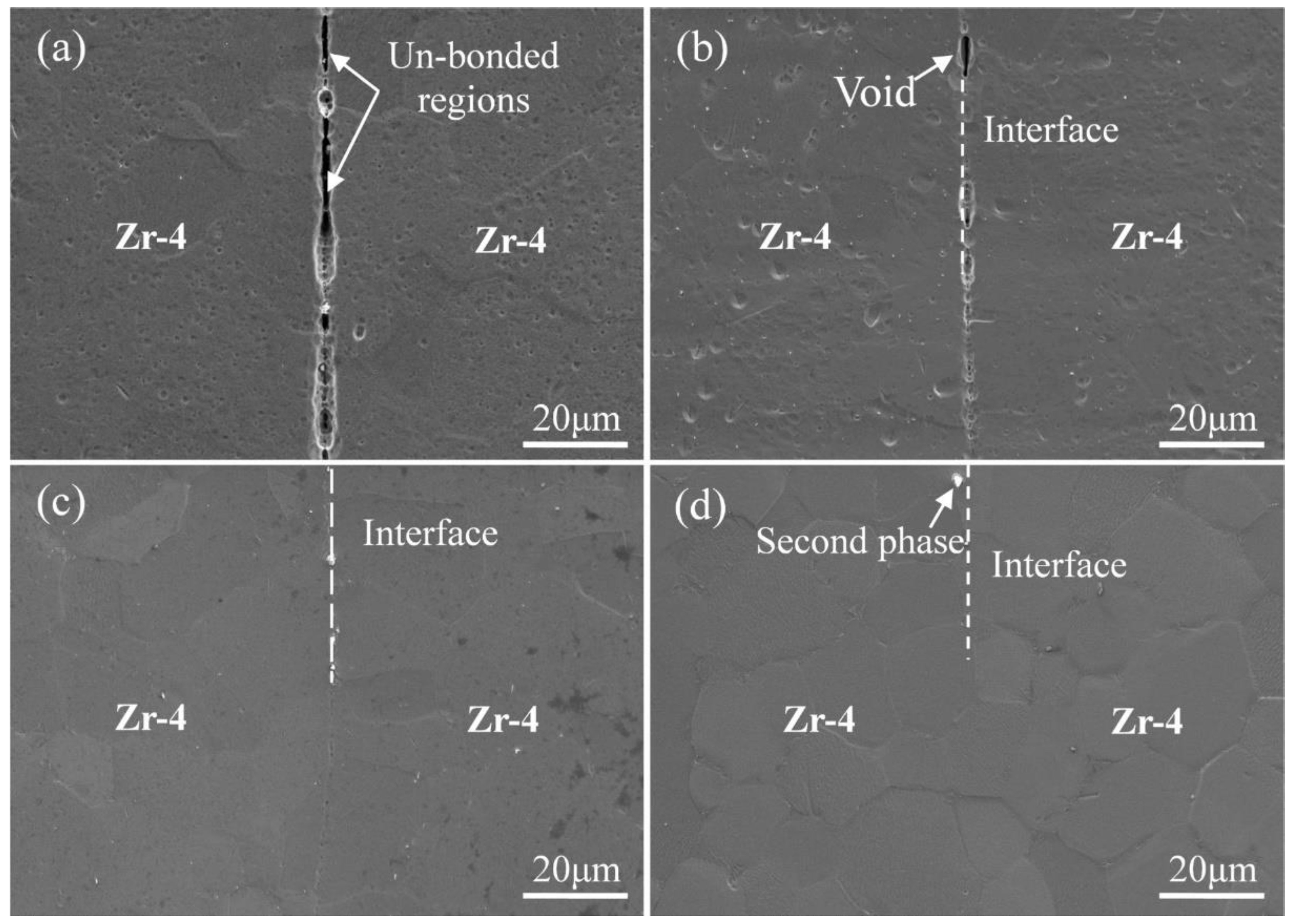
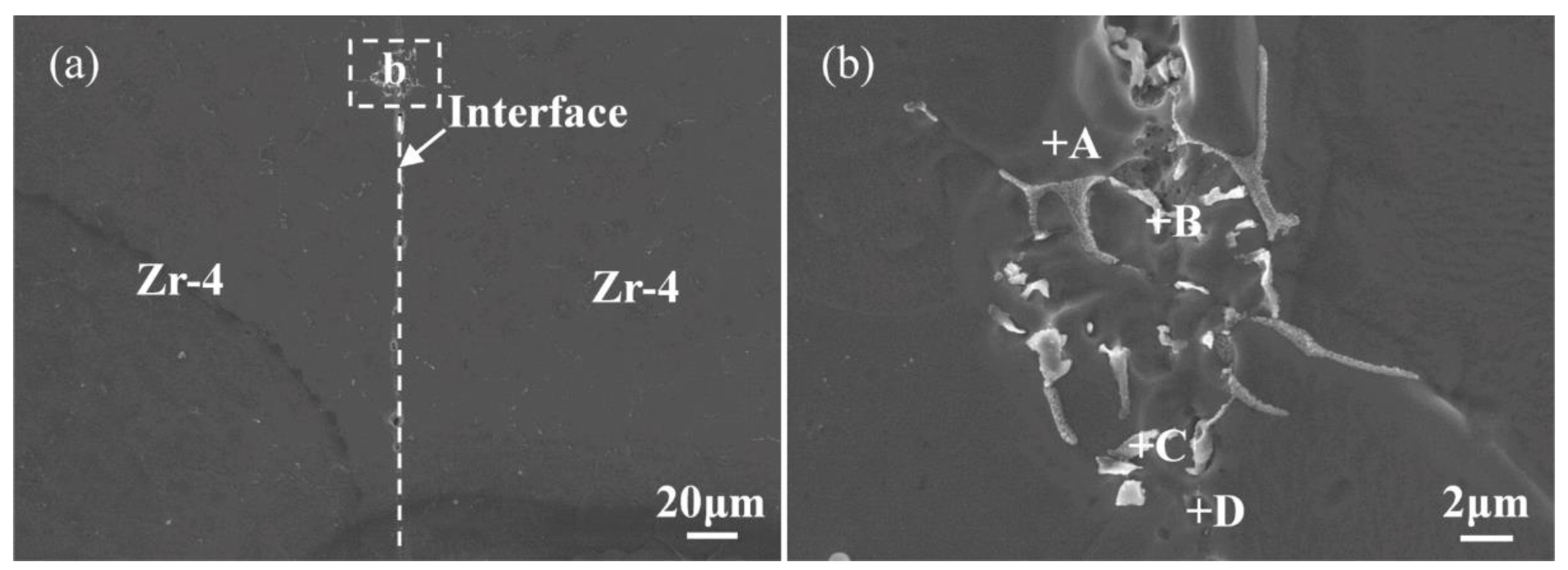
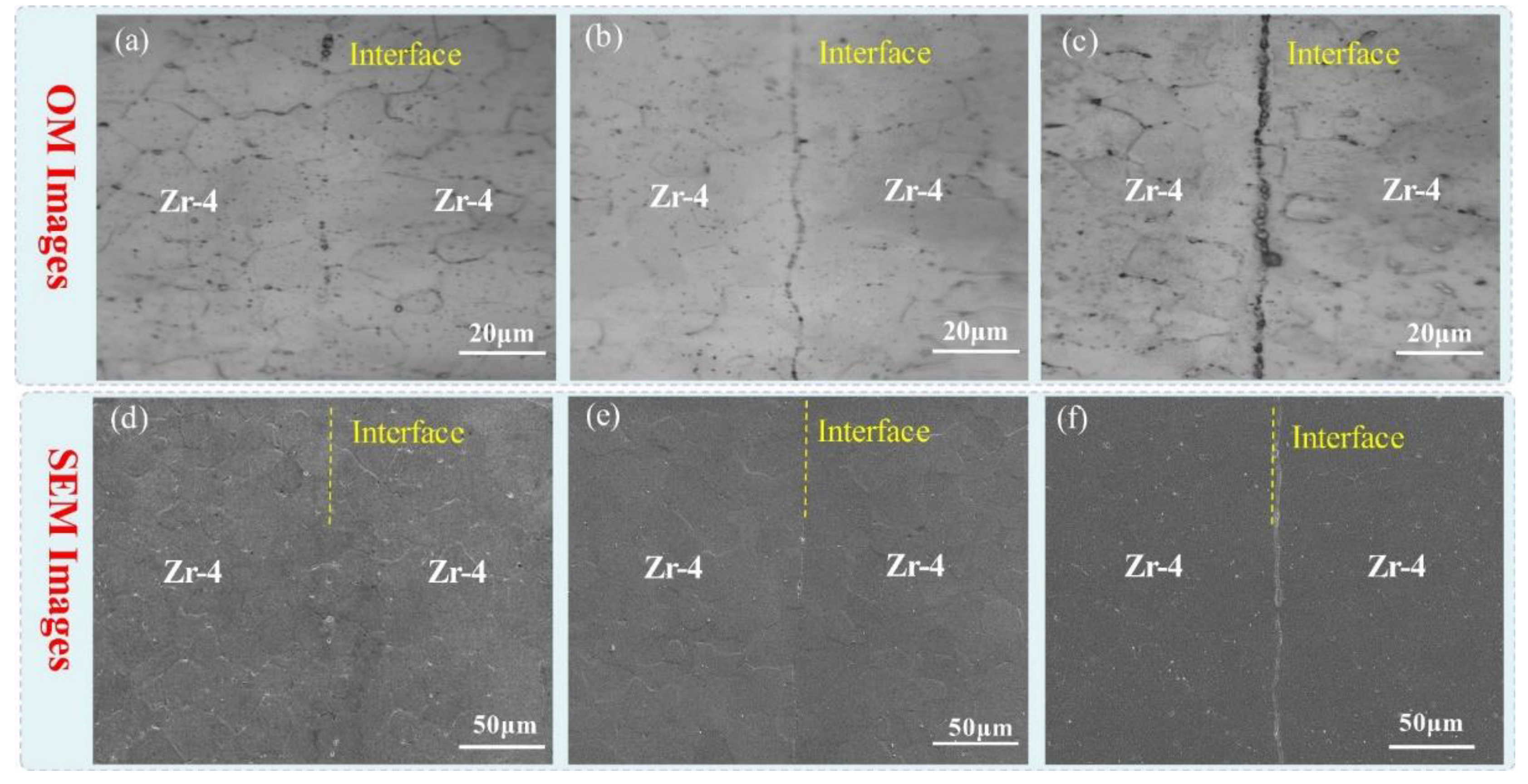
3.2. Analysis of the Interfacial Microstructure of Zr-4 Alloy Diffusion Bonding Joint

Figure 3 shows the microstructure of the diffusion bonded joints prepared at different bonding temperatures for a holding time of 60 min under a pressure of 7 MPa. It can be seen that there are many un-bonded regions and voids at the bonding interface when the diffusion temperatures were 760 and 780 °C. When the temperature reaches 800 or 820 °C, the voids are significantly reduced. It can be concluded that the joint is well bonded at 800 and 820 °C, and there are very few un-bonded regions or voids appeared as observed in Figure 3c,d. At the same time, it can be observed that there are second phases precipitated at the joint interface when the bonding temperature is above 800 °C.
To further evaluate the bonding interface of the Zr-4 alloy, the micro-metallographic theoretical calculation method was used to preliminarily calculate the interface bonding ratio of the prepared bonding interfaces, and the calculated results are shown in Table 2. As the bonding temperature increases, the interface bonding ratio shows an upward trend. The interface bonding ratio is higher than 92% when the bonding temperature is above 800 °C, indicating that the diffusion interface can form a good joint.
EDS was used to further determine the chemical composition of the second phase precipitated at the diffusion interface of Zr-4 alloy, as analyzed in Figure 4 and Table 3. The dark gray phase (points A and D) is the main component, which can be reasonably classified as α-Zr. Of note, its atomic ratio is very close to that of the Zr-4 alloy. The white phase (points B and C) segregated on the grain boundary and interface is the precipitated second phase. The atomic ratio of the elements in point C is close to the phase of Zr(Cr, Fe)2, which is in line with the reported results in the literature [26]. Additionally, the proportion of Fe in point B is lower than that in point C. According to the previous reports [15,26], it can be determined that the corresponding phase in point B should be eutectic α-Zr + Zr(Fe, Cr)2.
Zr-4 alloy mainly contains three alloying elements, which are Sn, Fe, and Cr. Sn has a higher solubility in Zr [27] and generally forms a solid solution with Zr, so it rarely participates in the precipitation of the second phase. As for Fe and Cr, the solubility of Cr in Zr is lower than Fe, so the diffusion of Cr in Zr is more difficult. Thus, the content of Cr (12.72 at. %) in the second phase is much lower than Fe (38.63 at. %). According to the Cr-Zr binary phase diagram [28], Cr mainly exists in the form of α-ZrCr2 in Zr when the temperature is below 836 °C (higher than the bonding temperature). The maximum atomic ratio of Fe in the second phase is 42.86 at. %. Based on the Fe-Zr binary phase diagram [29], it is found that Fe mainly exists in Zr2Fe and ZrFe2 when the Fe atomic ratio is greater than 32 at. % and the temperature is around 800 °C. Moreover, Zr2Fe will eutectoid decompose into ZrFe2 and Zr3Fe at a temperature below 775 °C. Since Cr and Fe can form a continuous solid solution in the solid-state, the existence of Zr(Cr, Fe)2 as the second phase is reasonable, and the main phase of the Zr-4 alloy is α-Zr. In part of the second phase, the atomic ratio of Zr is very large, indicating that the existence of eutectic α-Zr + Zr(Fe, Cr)2 is also reasonable. The Vickers hardness of Zr(Cr, Fe)2 is 1390 HV, which is much higher than that of Zr-4 alloy (~220 HV) [25]. Therefore, excessive brittle Zr(Cr, Fe)2 presented in joint will significantly reduce its plasticity, and it is likely to be the source of cracks, resulting in brittle fracture of diffusion bonding joints. Under this circumstance, retarding the formation of Zr(Cr, Fe)2 is beneficial to improving the performance of the joint.
Figure 5 shows the microscopic metallographic and SEM pictures of the interface of the diffusion joint prepared under the condition of 800 °C/7 MPa with different holding times. It can be seen that the amount of the second phase in the joint is gradually increasing with the increase of diffusion time. The formation of a large amount of the second phase leads to a high probability of the occurrence of voids after precipitation at the interface. Therefore, the holding time should not be so long that the second phase appears in large quantities. To further confirm the crystal phase in the joint, the XRD patterns of Zr-4 base material and the bonding interface bonded at 800 °C/7 MPa/60 min were measured as shown in Figure 6. The diffraction peak of the second phase is undetected due to its low content (Figure 3) and all peaks in the two patterns belong to α-Zr. Thus, there are very few second phases in the joint, which are undetectable by XRD.

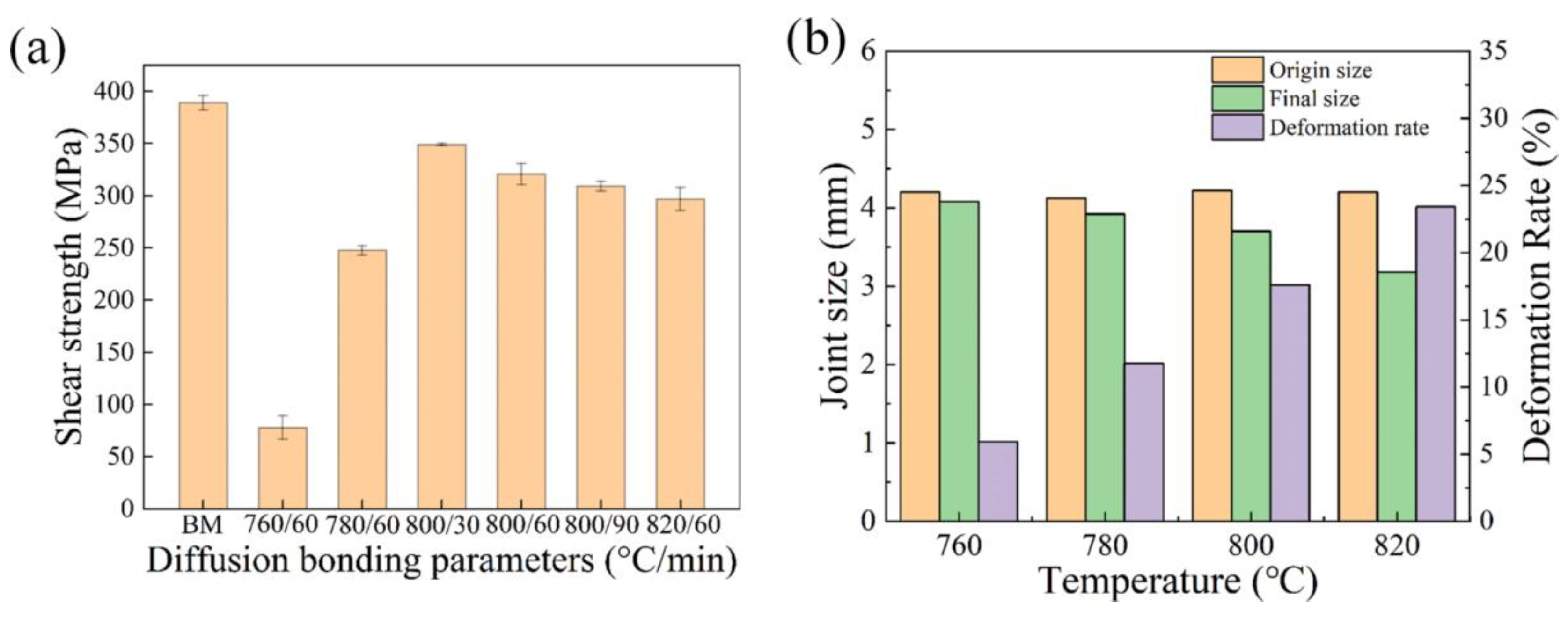
3.3. Influence of Diffusion Bonding Process Parameters on the Mechanical Properties of the Joints

Figure 7a shows the influence of different bonding temperatures and holding times on the shear strength of the joint under a pressure of 7 MPa. It can be seen that the shear strength of the diffusion bonded joints first increases and then decreases as the bonding temperature increases. When the bonding temperature is 800 °C, the shear strength is as high as 321 MPa, which reaches 82.5% of the Zr-4 base material (389 MPa). Based on the previous analysis, there are pores and un-bonded parts at the interface when the bonding temperature is 760 and 780 °C and the interface bonding ratio is relatively low. Therefore, their shear strength is low and the minimum value is only 67 MPa. As the bonding temperature increased to 820 °C, the grain size of the Zr-4 alloy and the amount of the second phase precipitated in the interface both increase significantly, resulting in the decrease of shear strength compared with the joint bonded at 800 °C.
As for the joint bonded in different holding times, the shear strength of the diffusion joint continues decreasing as the diffusion time increases. When the holding time is 30 min, the maximum shear strength of 349 MPa is obtained, reaching 89.7% of the Zr-4 base material. Additionally, the grain size of the Zr-4 alloy and the amount of the second phase are both increased when the holding time is extended to 90 min, which is harmful to the joint performance. As expected, the measured shear strength of the joint prepared with the holding time of 90 min is decreased to 305 MPa. Therefore, the prolongation of holding time is harmful to the performance of the bonded joint. Furthermore, it can be found that the fluctuation of shear strength induced by the holding time was smaller than that induced by bonding temperature.
To further explore the influence of bonding temperature on the shear strength of diffusion bonding joints, the deformation rate of diffusion joints at different bonding temperatures is analyzed, and the results are shown in Figure 7b. The joint deformation rate is gradually increasing with the increase of bonding temperature. When the bonding temperature reaches 820 °C, the joint deformation rate is close to 25%, which would also cause the decrease of shear strength due to the distortion of the bonding structure.

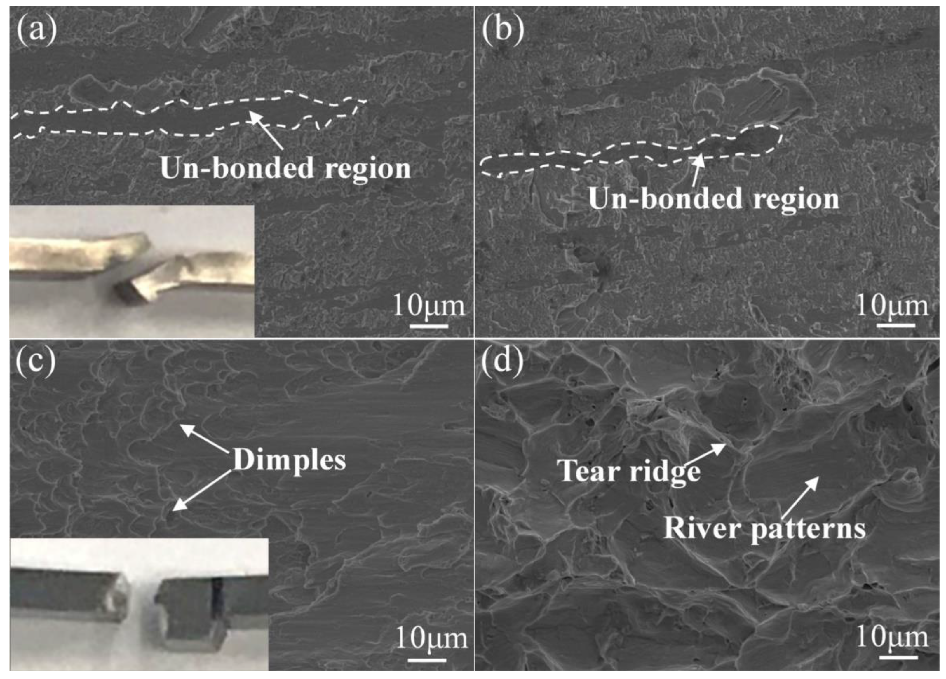
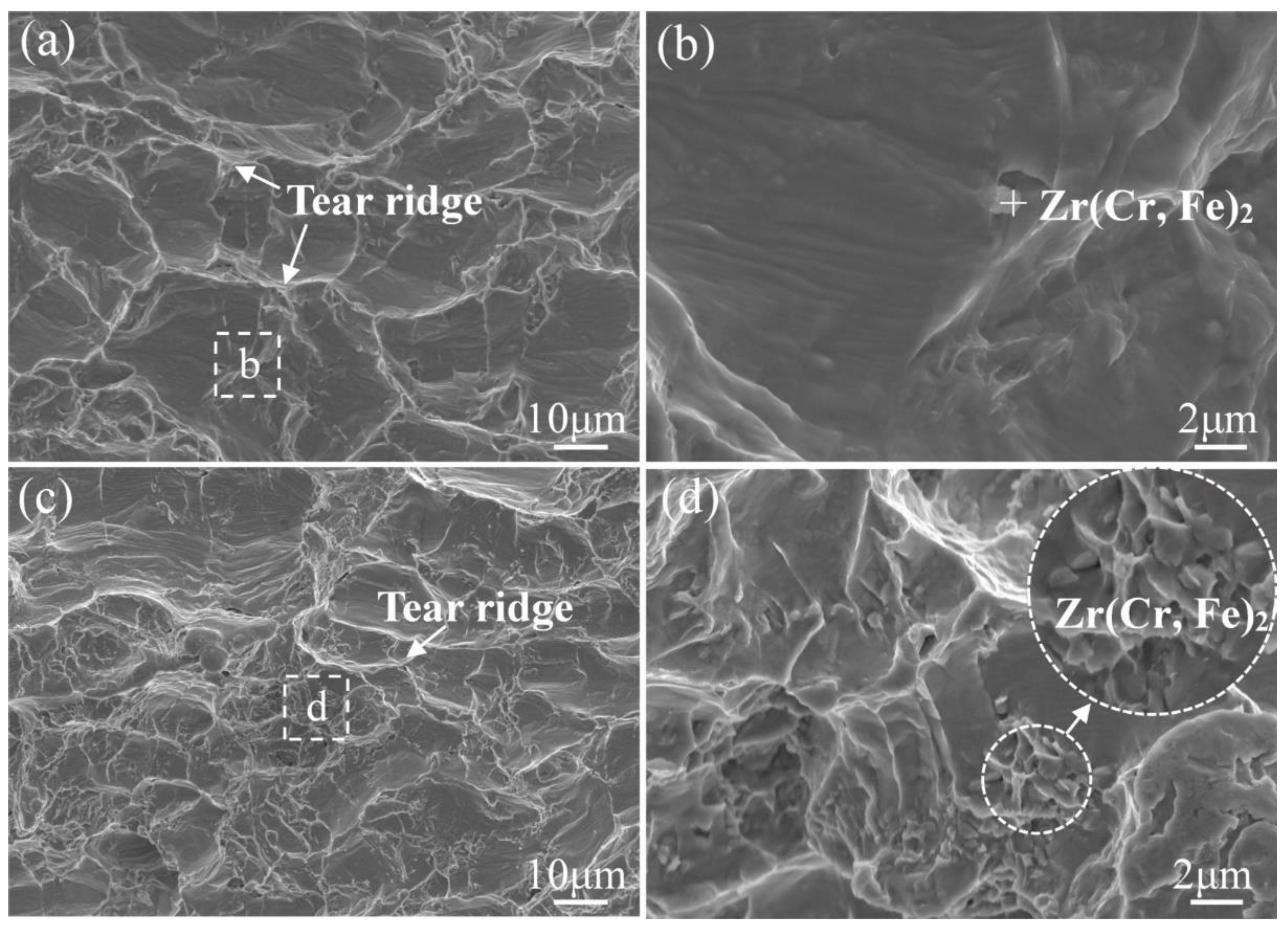
3.4. Analysis of Fracture Morphology of the Diffusion Bonded Joint

To clarify the influence mechanism of diffusion bonding process parameters on the shear strength of the joint, the morphology of the fracture surface after the shear test was analyzed. Figure 8 shows the fracture morphologies of the diffusion bonding joint prepared at different bonding temperatures. By observing the fracture position of the joint, two typical fracture types could be distinguished, which are broken at the interface of the joint (Figure 8a) and in the base material (Figure 8c). At a low bonding temperature (760 °C), it can be seen from Figure 8a,b that there are large un-bonded regions that appeared in the fracture and its morphology remains as the original α-Zr structure. This is consistent with the result that the joint prepared at this temperature has a low interface bonding ratio. Due to the un-bonded areas existing in the fracture surface, the actual bearing area is reduced during the shear experiment. Therefore, the crack initiates earlier in the un-bonded region and the specimen is fracturing along the interface at the joint, resulting in the low shear strength of the joint. The results confirm that the diffusion bonded Zr-4 alloy joint does not achieve an effective joining with the bonding temperature of 760 °C.
When the bonding temperature is increased to 800 °C, there are few un-bonded regions in the joint and the fracture occurs at the base material as shown in Figure 8c. It also found that dimples are presented in the fracture surface, indicating a gradual transition to ductile fracture. When the bonding temperature is 820 °C, some tear ridges can be observed in Figure 8d, accompanied by a river-like pattern. The river pattern surrounded by lots of tear ridges is short and curved with few tributaries, which confirms that the fracture is a quasi-cleavage fracture. This change of fracture model mostly results from the increase of crystal size (Figure 2f) and deformation rate of the joint prepared at high temperatures (Figure 7b). With the increase of the bonding temperature, the shear strength of the bonded joint is increased as a result of the high interfacial bonding ratio. However, the total thickness of the joint is greatly decreased due to the considerably large deformation rate at an excessively high bonding temperature, leading to the fracture occurring at the base material. Moreover, the strength of the Zr-4 alloy substrate was slightly decreased because of the growth of grain size. Thus, it can be concluded that too low (760 °C) and too high (820 °C) bonding temperatures both are detrimental to the mechanical properties of the joint. The former will induce the formation of un-bonded regions in the joint, and the latter will induce the increase of grain size, the formation of the brittle second phase, and the decrease of the thickness of joints.
The comparative analysis of fracture morphologies under different holding times is also conducted as shown in Figure 9. Figure 9a,b (30 min) shows the microscopic morphology of the fracture with a few river patterns, dimples, and tear ridges. It infers that the fracture is also a quasi-cleavage fracture. When the holding time is extended to 90 min (Figure 9c,d), there are more second phases observed than that in Figure 9a,b. Comparing the formed phase in the fracture of the two samples, the amount of the second phase, which is composed of Zr(Cr, Fe)2 and eutectic α-Zr + Zr(Fe, Cr)2, is greatly increased with the extension of the holding time. It can act as a crack source during fracture initiation and induce continuous crack propagation. Therefore, the shear strength of the diffusion joint is significantly reduced after the diffusion holding time is extended.

4. Conclusions

  • The bonding ratio of Zr-4 alloy diffusion joints gradually increases with the increase of bonding temperature and reaches the value of 92% above 800 °C. The shear strength of this diffusion joint reaches the largest value of 349 MPa at 800 °C for 30 min, which reaches 89.7% of the shear strength of Zr-4 alloy (389 MPa).
  • The increase of the bonding temperature and the extension of the holding time will contribute to the precipitation of the second phase in the joint. The second phase is mainly Zr(Cr, Fe)2 and eutectic α-Zr + Zr(Fe, Cr)2, which have higher hardness than the Zr-4 base material. It demonstrated that the second phase can reduce the interface bonding ratio and induce the formation of cracks during fracture initiation. Thus, retarding the formation of Zr(Cr, Fe)2 is significant to improving the mechanical properties of the joint.
  • Too low (760 °C) and too high (820 °C) bonding temperatures are detrimental to the mechanical properties of the joint. The low temperature will induce the formation of un-bonded regions in the joint, and the high temperature will induce the increase of grain size and the formation of a brittle second phase. Furthermore, the shear strength of the diffusion joint is significantly reduced after the diffusion holding time is extended due to the increase of the Zr(Cr, Fe)2 and eutectic α-Zr + Zr(Fe, Cr)2 phase.

Author Contributions

Conceptualization, Z.W., Z.Y. and Y.W.; methodology, X.Y., J.W. and K.S.; formal analysis, X.Y. and Z.X.; data curation, X.Y. and Z.X.; resources, Z.W., J.W. and F.Q.; writing—original draft preparation, Z.W.; writing—review and editing, Z.W., X.Y., F.Q., K.S. and Z.Y.; project administration, Y.W.; funding acquisition, Z.Y. and Y.W. All authors have read and agreed to the published version of the manuscript.

Funding

The authors gratefully acknowledge the financial supports from the National Natural Science Foundation of China (Grant No. 51875400), the Science and Technology Program of Tianjin (No.19ZXJRGX00100), and the Youth Talent Program of China National Nuclear Corporation (2019).

Data Availability Statement

Not applicable.

Conflicts of Interest

The authors declare no conflict of interest.

References

  1. Azam, A.; Rafiq, M.; Shafique, M.; Zhang, H.; Yuan, J. Analyzing the effect of natural gas, nuclear energy and renewable energy on GDP and carbon emissions: A multi-variate panel data analysis. Energy 2021, 219, 119592. [Google Scholar] [CrossRef]
  2. Zinkle, S.J.; Was, G.S. Materials challenges in nuclear energy. Acta Mater. 2013, 61, 735–758. [Google Scholar] [CrossRef]
  3. Anser, M.K.; Ahmad, M.; Khan, M.A.; Nassani, A.A.; Askar, S.E.; Zaman, K.; Abro, M.M.Q.; Kabbani, A. Progress in nuclear energy with carbon pricing to achieve environmental sustainability agenda: On the edge of one’s seat. Environ. Sci. Pollut. Res. 2021, 28, 34328–34343. [Google Scholar] [CrossRef] [PubMed]
  4. Ding, S.; Tao, Z.; Zhang, H.; Li, Y. Forecasting nuclear energy consumption in China and America: An optimized structure-adaptative grey model. Energy 2022, 239, 121928. [Google Scholar] [CrossRef]
  5. Xiao-Ding, L.; Yun-Huan, Q.; Li-Hui, Z.; Yu, G.; Yi-Man, D.; Guang-Hui, L. Forecast of China’s future nuclear energy development and nuclear safety management talents development. IOP Conf. Ser. Earth Environ. Sci. 2021, 691, 12022. [Google Scholar] [CrossRef]
  6. Zhan, L.; Bo, Y.; Lin, T.; Fan, Z. Development and outlook of advanced nuclear energy technology. Energy Strat. Rev. 2021, 34, 100630. [Google Scholar] [CrossRef]
  7. Terrani, K.A. Accident tolerant fuel cladding development: Promise, status, and challenges. J. Nucl. Mater. 2018, 501, 13–30. [Google Scholar] [CrossRef]
  8. Schino, A.D. Manufacturing and applications of stainless steels. Metals 2020, 10, 327. [Google Scholar] [CrossRef] [Green Version]
  9. Bailly-Salins, L.; Borrel, L.; Jiang, W.; Spencer, B.W.; Shirvan, K.; Couet, A. Modeling of high-temperature corrosion of zirconium alloys using the extended finite element method (X-FEM). Corros. Sci. 2021, 189, 109603. [Google Scholar] [CrossRef]
  10. Zhang, Y.; Qi, H.; Song, X. Expansion deformation behavior of zirconium alloy claddings with different hydrogen concentrations. J. Nucl. Mater. 2021, 554, 153082. [Google Scholar] [CrossRef]
  11. Yun, D.; Lu, C.; Zhou, Z.; Wu, Y.; Liu, W.; Guo, S.; Shi, T.; Stubbins, J.F. Current state and prospect on the development of advanced nuclear fuel system materials: A review. Mater. Rep. Energy 2021, 1, 100007. [Google Scholar] [CrossRef]
  12. Ahmad, M.; Akhter, J.; Shaikh, M.; Akhtar, M.; Iqbal, M.; Chaudhry, M. Hardness and microstructural studies of electron beam welded joints of Zircaloy-4 and stainless steel. J. Nucl. Mater. 2002, 301, 118–121. [Google Scholar] [CrossRef]
  13. Lee, J.G.; Lim, C.H.; Kim, K.H.; Park, S.S.; Lee, M.K.; Rhee, C.K. Brazing characteristics of a Zr-Ti-Cu-Fe eutectic alloy filler metal for Zircaloy-4. J. Nucl. Mater. 2013, 441, 431–438. [Google Scholar] [CrossRef]
  14. Lee, M.K.; Lee, J.G.; Kim, K.H.; Lim, C.H.; Rhee, C.K.; Park, C.H. Amorphous sputter coating of a multi-component Zr-Ti-Ni-Cu alloy as a filler for brazing Zircaloy-4. J. Nucl. Mater. 2012, 426, 9–15. [Google Scholar] [CrossRef]
  15. Ahmad, M.; Akhter, J.I.; Akhtar, M.; Iqbal, M. Microstructure and characterization of phases in TIG welded joints of Zircaloy-4 and stainless steel 304L. J. Mater. Sci. 2007, 42, 328–331. [Google Scholar] [CrossRef]
  16. Wang, Z.; Guo, Y.; Ren, L.; Quan, G.; Liu, Y.; Pan, H. Effect of bonding temperature on microstructure and mechanical properties of 304L/Zircaloy-4 diffusion-bonded joints with Ni/Ta hybrid interlayer. Adv. Eng. Mater. 2021, 2100555. [Google Scholar] [CrossRef]
  17. Parga, C.; van Rooyen, I.; Coryell, B.; Lloyd, W.; Valenti, L.; Usman, H. Room temperature mechanical properties of electron beam welded zircaloy-4 sheet. J. Mater. Process. Technol. 2017, 241, 73–85. [Google Scholar] [CrossRef] [Green Version]
  18. Mukherjee, D.; Panakkal, J.P. Interaction between SS-302 and Zircaloy during fuel pin welding. J. Mater. Sci. Lett. 1995, 14, 1383–1385. [Google Scholar] [CrossRef]
  19. Rodriguez, N.; Dickinson, T.; Nguyen, D.H.; Park, E.; Foyos, J.; Sutherlin, R.; Sparkowich, S.; Hogue, F.; Stoyanov, P.; Ogren, J.; et al. On the bimodal grain growth in zirconium grade 702 alloy. Eng. Fail. Anal. 2008, 15, 440–444. [Google Scholar] [CrossRef]
  20. Liu, X.; Cinbiz, M.N.; Kombaiah, B.; He, L.; Teng, F.; Lacroix, E. Structure of the pellet-cladding interaction layer of a high-burnup Zr-Nb-O nuclear fuel cladding. J. Nucl. Mater. 2021, 556, 153196. [Google Scholar] [CrossRef]
  21. Raj, B.; Vijayalakshmi, M.; Rao, P.V.; Rao, K. Challenges in materials research for sustainable nuclear energy. MRS Bull. 2008, 33, 327–337. [Google Scholar] [CrossRef] [Green Version]
  22. Was, G.; Petti, D.; Ukai, S.; Zinkle, S. Materials for future nuclear energy systems. J. Nucl. Mater. 2019, 527, 151837. [Google Scholar] [CrossRef]
  23. Li, C.; Si, X.; Bian, S.; Dong, Z.; Huang, Y.; Qi, J.; Feng, J.; Cao, J. Diffusion bonding of Ti and Zr at ultra-low temperature via surface nano-crystallization treatment. Mater. Sci. Eng. A 2020, 785, 139413. [Google Scholar] [CrossRef]
  24. Yang, Z.; Chen, Y.; Niu, S.; Wang, Y.; Han, Y.; Cai, X.; Wang, D. Phase transition, microstructural evolution and mechanical properties of Ti-6Al-4V and Ti-6.5Al-3.5Mo-1.5Zr-0.3Si joints brazed with Ti-Zr-Ni-Cu filler metal. Arch. Civ. Mech. Eng. 2020, 20, 88. [Google Scholar] [CrossRef]
  25. Taouinet, M.; Kamel, N.E.; Lebaili, S. Diffusion bonding between Zircaloy-4 and 304L stainless steel in the presence of a eutectic. Mater. Manuf. Process. 2013, 28, 1327–1334. [Google Scholar] [CrossRef]
  26. Taouinet, M.; Lebaili, S.; Souami, N. Characterization of the interface to diffusion bonding of zircaloy-4 and stainless steel. Phys. Procedia 2009, 2, 1231–1239. [Google Scholar] [CrossRef] [Green Version]
  27. Chemelle, P.; Knorr, D.; Van Der Sande, J.; Pelloux, R. Morphology and composition of second phase particles in zircaloy-2. J. Nucl. Mater. 1983, 113, 58–64. [Google Scholar] [CrossRef]
  28. Okamoto, H. Supplemental literature review of binary phase diagrams: B-Fe, Cr-Zr, Fe-Np, Fe-W, Fe-Zn, Ge-Ni, La-Sn, La-Ti, La-Zr, Li-Sn, Mn-S, and Nb-Re. J. Phase Equilibria Diffus. 2016, 37, 621–634. [Google Scholar] [CrossRef]
  29. Stein, F.; Sauthoff, G.; Palm, M. Experimental determination of intermetallic phases, phase equilibria, and invariant reaction temperatures in the Fe-Zr system. J. Phase Equilibria Diffus. 2002, 23, 480–494. [Google Scholar] [CrossRef]
Figure 1. Schematic diagram of the diffusion bonding assembly.
Crystals 11 01437 g001
Figure 2. Microstructure of Zr-4 alloy after different thermal cycling treatment: (a) base material, (b) 760 °C/60 min, (c) 780 °C/60 min, (d) 800 °C/60 min, and (e) 820 °C/60 min, (f) the grain size of Zr-4 alloy after heat treatment at different temperatures.
Crystals 11 01437 g002
Figure 3. SEM images of the microstructure of the joint diffusion bonded at different temperatures (7 MPa/60 min): (a) 760 °C, (b) 780 °C, (c) 800 °C, and (d) 820 °C.
Crystals 11 01437 g003
Figure 4. SEM images of the magnified microstructure of diffusion interface under 820 °C/7 MPa/60 min, and (b) is a magnification image in (a).
Crystals 11 01437 g004
Figure 5. The microscopic metallographic and SEM images of the joints diffusion bonded at 800 °C/7 MPa: (a,d) 30 min, (b,e) 60 min, and (c,f) 90 min.
Crystals 11 01437 g005
Figure 6. XRD analysis of Zr-4 base material and the joint bonded at 800 °C for 7 MPa under 60 min.
Crystals 11 01437 g006
Figure 7. Influence of bonding parameters on shear strength and deformation of diffusion interface. (a) bonding temperature and holding time, and (b) deformation rate of the joints.
Crystals 11 01437 g007
Figure 8. Fracture morphologies of the joint bonded at different temperatures (7 MPa/60 min): (a,b) 760 °C, (c) 800 °C, and (d) 820 °C, and insert pictures are the physical pictures of the broken joints.
Crystals 11 01437 g008
Figure 9. Fracture morphologies of the joint bonded for different holding times (800 °C/7 MPa): (a,b) 30 min and (c,d) 90 min.
Crystals 11 01437 g009
Table 1. Chemical composition and possible phase of each point marked in Figure 2d (at. %).
PointZrSnCrFePossible Phase
A37.5200.3818.6343.47Zr(Cr, Fe)2
B31.090.2323.2445.44Zr(Cr, Fe)2
C43.200.4717.6138.72Zr(Cr, Fe)2
Table 2. Interface bonding ratio of the joints prepared at different bonding temperatures.
Bonding Temperature (°C)760780800820
Interface Bonding ratio74%83%92%95%
Table 3. Chemical composition and possible phase of each point marked in Figure 4b (at. %).
PointZrSnCrFePossible Phase
A92.5201.7601.6604.06α-Zr
B47.8700.7812.7238.63Eutec. α-Zr + Zr(Fe, Cr)2
C43.7000.7512.6942.86Zr(Cr, Fe)2
D95.0102.2901.0101.69α-Zr
Publisher’s Note: MDPI stays neutral with regard to jurisdictional claims in published maps and institutional affiliations.

