Article

Dosimeter Based on YAG: Ce Phosphor via Sol-Gel Method for Online X-ray Radiation Monitoring

1
Key Laboratory of Specialty Fiber Optics and Optical Access Networks, Shanghai University, 99 Shangda Road, Shanghai 200444, China
2
Photonics & Optical Communications, School of Electrical Engineering & Telecommunications, University of New South Wales, Sydney, NSW 2052, Australia
*
Author to whom correspondence should be addressed.
Submission received: 15 November 2021 / Revised: 8 December 2021 / Accepted: 13 December 2021 / Published: 16 December 2021
(This article belongs to the Special Issue Single-Crystalline Composition Materials)

Abstract

:
This paper focuses on the preparation of cerium-doped yttrium aluminum garnet (YAG: Ce) powder with several concentration gradients via the sol-gel method by detecting its structural characteristics via X-ray diffraction (XRD) patterns and scanning electron microscope (SEM) to verify the generation of a complete crystal phase and evenly distributed nanopowder. On this basis, the luminescence characteristics of Ce3+ are explored, the mechanism and model are discussed based on the spectra, and the ideal doping concentration was obtained by comparing the luminescence intensity along with the fluorescence quenching theory and fluorescence decay spectra of samples with different doping concentrations. Several radiation dosimeters based on YAG: Ce phosphors were made; the online radiation monitoring function was realized under the exposure of a standard X-ray source; the repeatability, accuracy, and sensitivity of the system were verified by experiments; and the factors affecting dosimeter response are discussed. This paper verifies the possibility of adhibiting YAG: Ce fluorescent powder for online X-ray monitoring, and lays the foundation for further research.

1. Introduction

X-rays were originally used for medical imaging diagnostics and X-ray crystallography for monitoring free radiation, a harmful ray to the human body, and are of great significance in terms of daily life [1,2], medicine [3,4,5,6,7], industry [8,9], etc. In a variety of X-ray detectors, the ionization chamber (ion chamber) is the “golden standard” for radiation detection, but it can only measure in vitro, requires relatively high measurement conditions, and is rather costly [10,11]; a film dosimeter is wearable but very precise position control is required to obtain accurate and high-resolution results [12,13]; the semiconductor dosimeter is outstanding in portability and resolution, but it has poor radiation resistance and a corresponding shorter service life [14,15]. Due to their high sensitivity, low delay, low loss, and other virtues, fiber dosimeters are becoming more and more favored [16], but fiber under a high-energy beam will lead to the Cherenkov effect, which will produce an interfering light signal mainly distributed around 500 nm [17,18,19], undermining the reliability. The phosphor cerium-doped yttrium aluminum garnet (YAG: Ce) not only has a fast scintillation decay (−70 nm), high light yield efficiency (−28,000 to 30,000 photons/MeV), but also has an emission peak of −550 nm to avoid the stem effect caused by the Cherenkov effect, and shows great prospects in radiation detection [4,16,20,21].
Currently, the methods of preparing YAG: Ce powders are the solid phase method and the liquid phase method [22,23]. The former is represented by the high-temperature solid phase method, a mature and widely used method in industrial production, but the reaction temperature is high, and the grain size of the generated sample is large, not suitable for research. On the other hand, with a greatly reduced reaction temperature, the liquid phase method to produce an ultrafine powder with rather uniform characteristics has been favored by laboratories. The coprecipitation method [24] and sol-gel method [25] are commonly used liquid phase methods; the former is of high efficiency and chemical uniformity, but the production process is complex, and requirements are demanding. Meanwhile, the sol-gel method is more friendly and simpler to generate solid metal oxides with even better chemical uniformity. The doping concentration and sintering atmosphere determine the materialized properties of the powder to a great extent, and in earlier work, we studied the luminescence and radiation characteristics of the powder material by the coprecipitation method [26] and sol-gel method [27], respectively.
In this paper, the optical and radiation properties of YAG: Ce samples with different concentrations of gradients prepared by the sol-gel method are studied, the optical dosimeter based on optical fiber were set, and the real time measurement of radiation was realized by low-dose X-ray irradiation, with an ideal response obtained.

2. Materials and Methods

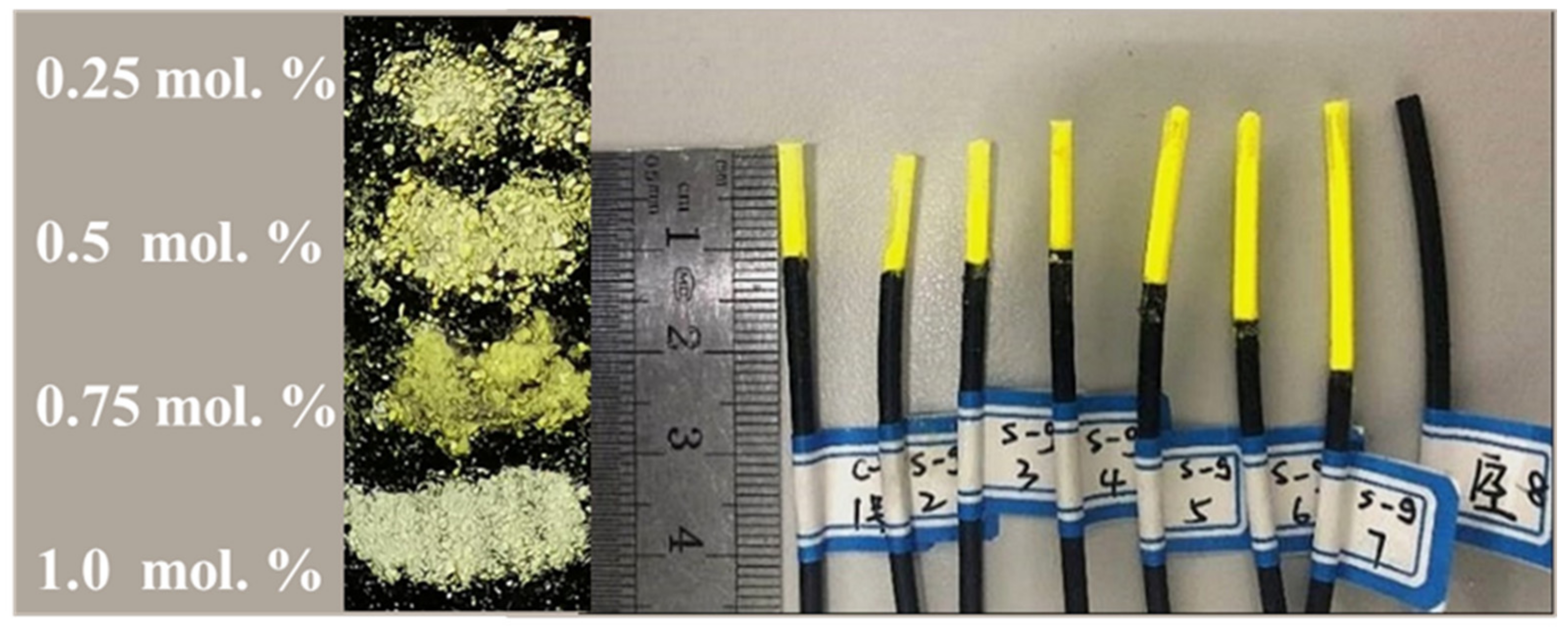
2.1. Powder Synthesis

YAG: Ce fluorescent powder was prepared by the sol-gel method: Ce(NO3)3·6H2O, Y(NO3)3·6H2O, and Al(NO3)3·9H2O were dissolved in deionized water, according to three concentrations of 0.15 mol/L, 0.09 mol/L, and 0.015 mol/L. We applied a low-frequency ultrasonic cleaner to accelerate dissolution, taking Ce ion doping concentrations of different molar percentages (0.25, 0.5, 0.75, and 1.0 mol.%.), mixing the quantitative rare earth solution in the beaker, using glycolate as a complexant, and then placing the solution in a 100 °C oil bath heated magnetic mixer, stirring for 6 h to form a sol. Then, we placed the sol in a vacuum drying tank where the temperature was kept at 100 °C until the dried precursor was obtained; the precursor after drying was blocky. For even heating during the sintering process, agate mortar was used to grind the precursor to a fine powder for further experiments. Then, the sample was placed in a tube furnace purging nitrogen in order to fully remove the water of the precursor to make sure crystallization. The sintering temperature was set to 1400 °C. The sintering slowly heated at 5 °C /min, and stayed at a temperature of 700 °C and 1100 °C for 2 h after heating to a constant temperature of 1400 °C for 2 h. The furnace cooled naturally and the final samples were obtained.

2.2. Fabrication of Dosimeter

Figure 1 shows the dosimeter of fluorescent powder as a coating material applied around the transmission fiber as a sensing center, encapsulated in a YAG: Ce powder dosimeter with a diameter of about 1.5 mm. The left side of the physical picture corresponds to the sol-gel method’s different doping concentration samples; doping concentration increases from top to bottom.
Polymethylmethacrylate (PMMA) fiber without YAG: Ce powder coating functions as a control group, representing the radiation background. The real radioluminescence (RL) response should be acquired by removing the background signal from the radiation signal of dosimeters fabricated with different parameters, as shown in Table 1. The dosimeter numbered 8 served as a control group to show the background signal during irradiation. To reduce the impact of external light in the experiment, dosimeters were wrapped in opaque cylindrical black tubes.

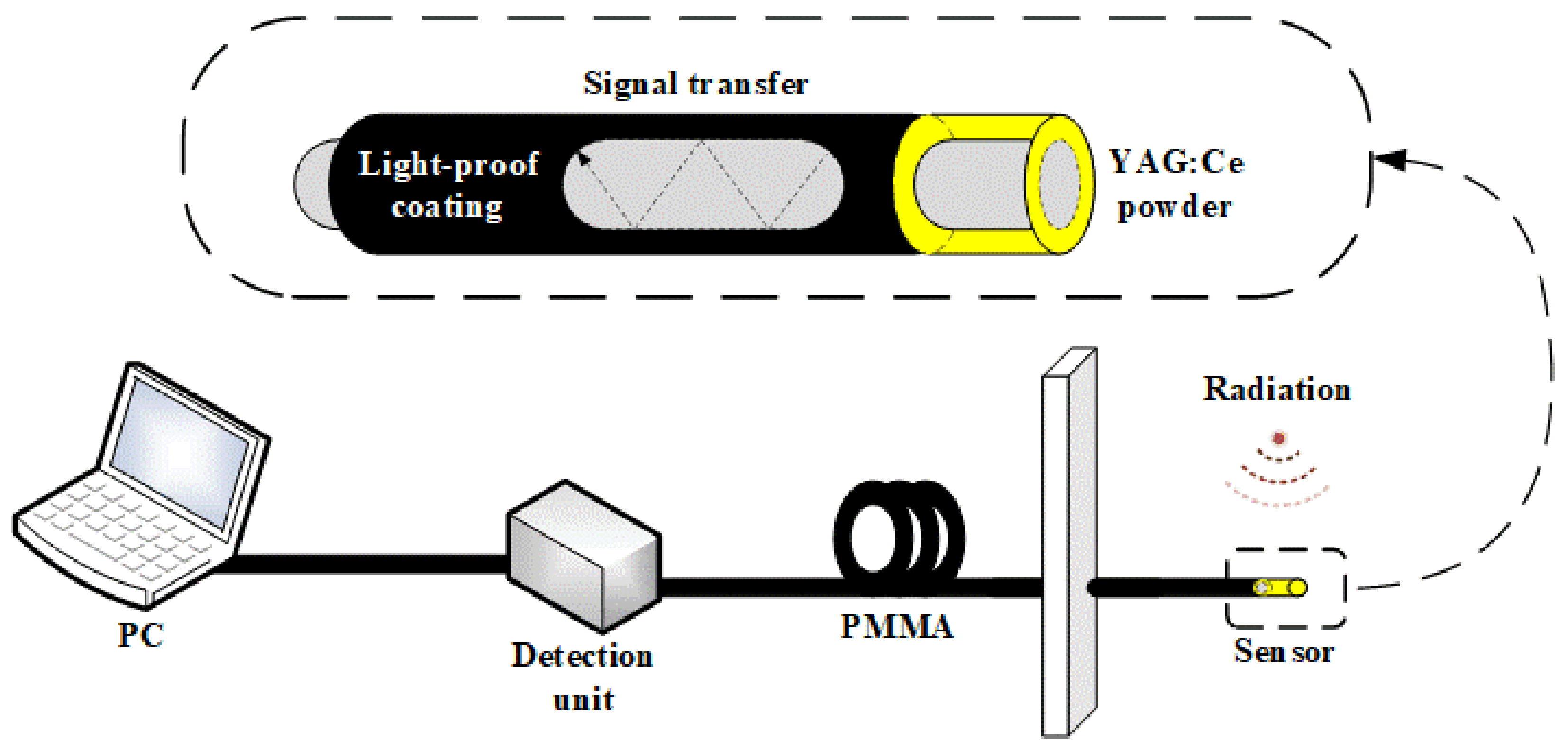
2.3. Detection System

According to the previous section, we chose the Ce concentration of 0.5 mol.% YAG: Ce powder to make replaceable dosimeters, the structure of which is shown in the dashed line box of Figure 2. Based on the dosimeters, a radiation detection system was built; dosimeters under X-ray irradiation would produce optical signals, which then transmit through the transmission fiber through a photomultiplier tube (PMT) acting as an optoelectronic detector. Data were recorded on a computer for further processing.

3. Results

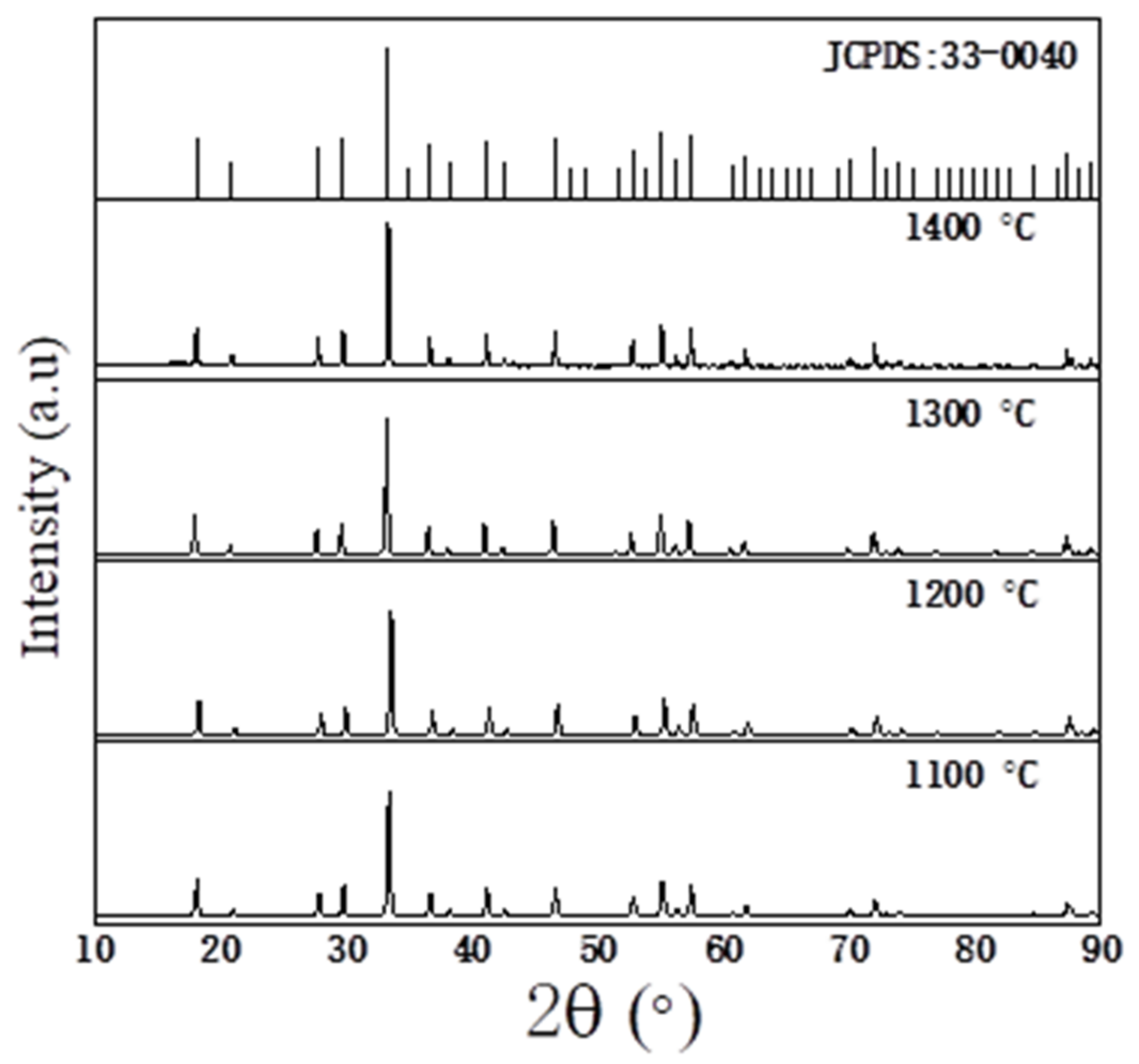
3.1. Characterization of XRD

Phase identification was performed using an X-ray diffraction (XRD) spectroscopy Rigaku D/Max 2500 V/PC rotating-target X-ray diffractometer (Rigaku, Tokyo, Japan); the radiation source was Cu Kα1 (λ = 0.15406 nm), the scanning speed was 5 °/min, and the scanning angle was 10°–90°. The morphology and particle size of the samples were detected on a scanning electron microscope (FE-SEM JSM 7500F, JEOL, Tokyo Japan).
In previous studies [26,27], it was found that sintering samples under nitrogen atmosphere obtains better results, so a nitrogen atmosphere was selected when the samples in this paper were prepared. At the same time, the XRD spectrum of samples sintered at different temperatures showed a slight difference, as shown in Figure 3. Although the peak shape of samples burned at different temperatures is not exactly the same, compared with the standard spectrum, they all have the same peak level, reflecting that the samples have formed a mature and stable YAG: Ce structure. With the increase in sintering temperature, it is found that the diffraction peak strength increases and the full width at half maximum (FWHM) narrows, meaning the crystallization increases, and there are no other phases generated, indicating the purity.
The average grain size of the YAG: Ce crystal sample, shown in Equation (1), was calculated by the Scherrer formula:
D = k λ β cos θ
where β is the FWHM of the selected peak, θ is the Bragg angle, λ is the wavelength of X-rays, k is the constant (when β represents FWHM, k takes 0.89), and D is the sample grain size of the sample [27,28,29]. Table 2 shows the estimated grain size of YAG: Ce powder synthesized by the sol-gel method; the grain size is relatively small, ranging from 57 to 73 nm, and the sample of 1400 °C has the smallest grain size, making it easier to evenly distribute, forming a stabler lattice structure, and contributing to better optical characteristics among the samples. The estimated error of the grain size is about 10%. The results of the Scherrer formula only serve as an assistant to obtain results of the order of magnitude due to the instrument measurement error and other factors deviating from the constant of the Scherrer formula.
The grain size obtained using Equation (1) was based on the average of the theoretical and empirical formulas; the real microscopic characterization of a certain object can be analyzed with scanning electron microscope(SEM) experiments [30,31,32,33], and to ensure the complete generation of the YAG: Ce phase, samples with different doping concentrations sintered at 1400 °C were selected for SEM testing, including samples with four concentration gradients, as shown in Figure 4.
Through SEM mapping, it was found that the distribution of the YAG: Ce powder prepared by the sol-gel method was rather uniform; the effect of the doping concentration on SEM pattern is not obvious. It was also found that with the increase in doping concentration, the powder color deepens to some extent, which is consistent with the change of the color of the YAG: Ce crystal with a higher Ce doping concentration. The size of particles with irregular shapes and porous texture is obviously larger than grains built by hard-agglomerated submicrometer grains and pores in nanometer size. The submicrometer grains were about a hundredth of nm. The sample performance of the four doping samples was analyzed in terms of morphology and microstructure obtained from SEM mapping. Glycolate-derived gel consisted of agglomerates with a highly porous, multimodal mixture of crystallite structure [34]; the regular microstructure of such a method can be observed in Figure 4a,b, whereas in Figure 4c, the grains are nonuniform. For the latter sample together with that in Figure 4d, the vision is too bright, suggesting that conductivity worsened as the concentration increased. In comparing the morphology and microstructure of four samples, we concluded that 0.25 and 0.5 mol.% Ce doping samples are in good agreement in distribution and have a relatively uniform size.

3.2. Optical Properties

PL spectra of YAG: Ce powders with different Ce doping concentrations grown in an inert atmosphere were measured using a fluorescence spectrometer (FS980, Edinburgh Instruments, Livingston, UK) with an xenon lamp excitation. The decay spectra were measured on a spectrofluorometer (Photon Technology International QM-TM-NIR, Birmingham, NJ, USA) equipped with a 460 nm continuous-wave laser diode (LD) as the excitation source.

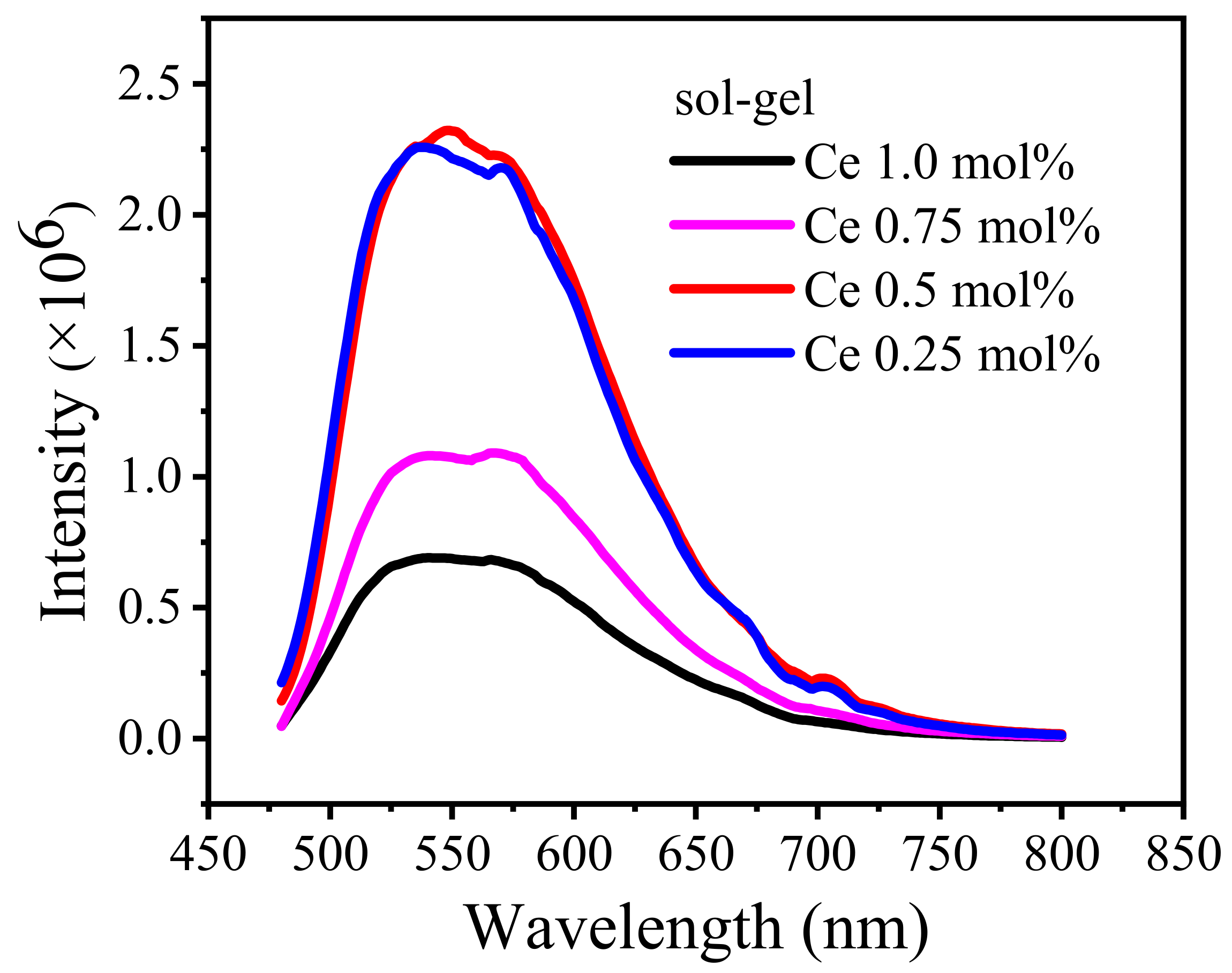
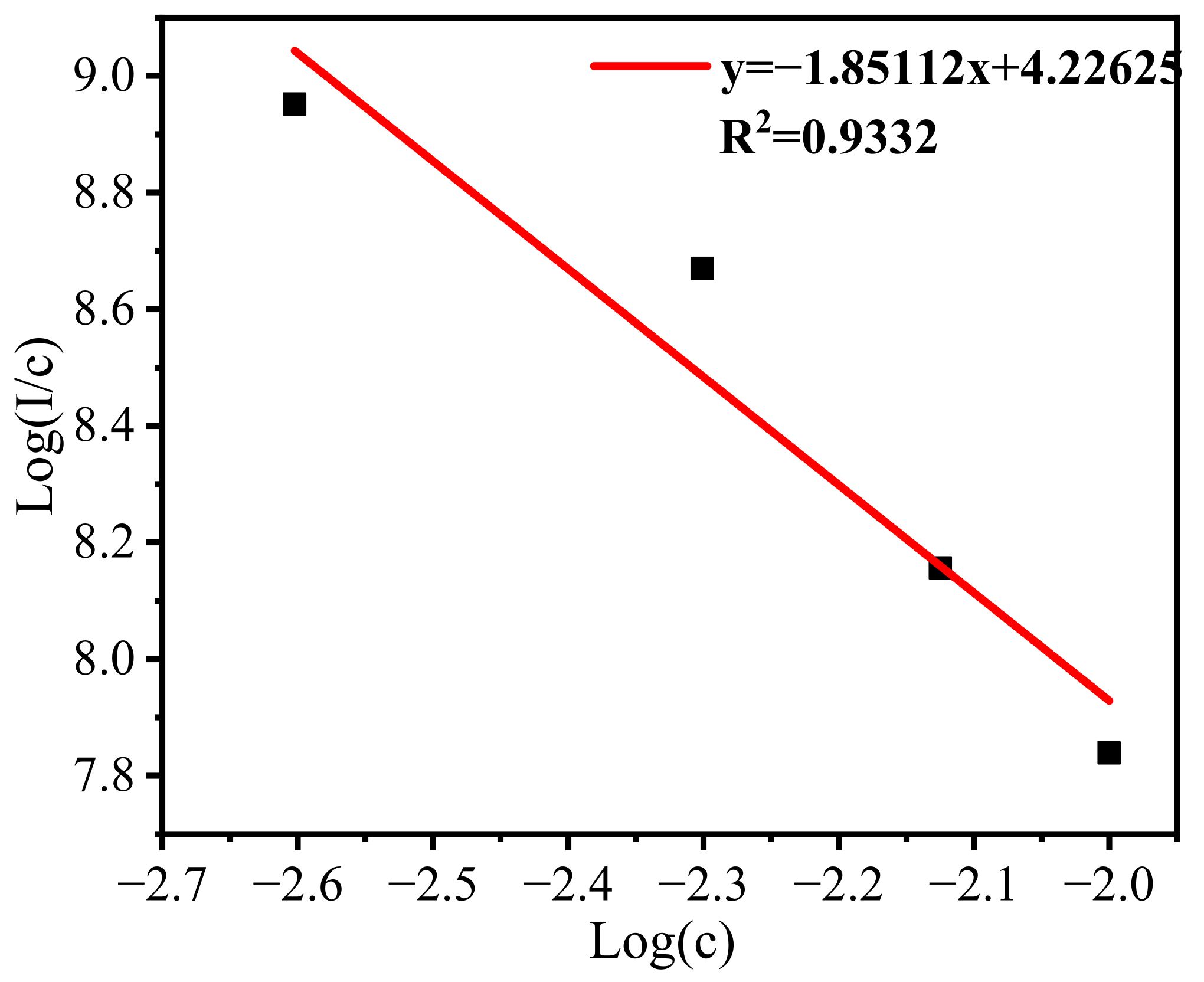
3.2.1. Photoluminescence Properties

Under the emission monitoring wavelength of 550 nm (2.25 eV), the excitation spectrum of YAG: Ce powders produced two main excitation bands at 340 nm (3.65 eV) and 460 nm (2.7 eV), respectively, shown in Figure 5. Gauss decomposition of the emission peaks at 460 nm produced two fitted peaks: 515 nm (2.41 eV) and 580 nm (2.14 eV), with an energy difference of 0.27 eV. The luminescence of the Ce3+ was due to the excited state of 5d transition to the ground state of 4f; the Ce3+ replaces the position of Y3+ in the YAG crystal, and under the action of the crystal field, the 4f ground state splits into two free ion states, namely, 2F7/2 and 2F5/2. Research has shown that in different substrates, the energy levels formed by the coupling of the spin orbit are different, and the energy difference is about 0.25 to 0.31 eV [35]. The energy difference between the two fitted peaks in Figure 5 is 0.27 eV, which is consistent with the results in the literature, so it can be determined that the luminescence of the two energy gaps corresponds to the transition of Ce3+ from 5d to 2F7/2 and 2F5/2, and it therefore produced two main excitation bands at 340 nm and 460 nm.
The emission spectra are shown in Figure 6; the spectrum with different Ce3+ doping concentrations was compared to ensure accuracy, all samples were under a 460 nm excitation, and tests were carried out under the same conditions. As shown in Figure 6, the main peak of all samples was around 550 nm, which can be attributed to the 5d–4f transition of Ce3+ in the YAG matrix.
All samples were prepared via the same method and sintering conditions, resulting in a similarity in the main peak position. By comparing the intensity of the emission peak of the four samples, we can find the ideal Ce ion doping concentration is 0.5 mol.%. The intensity of the emission spectrum is the highest among the tested samples. With the increase in the Ce ion doping concentration, intensity decreases gradually, indicating that nonradiation transition or fluorescence quenching might have occurred.
When the doping concentration is relatively low, the distance between the luminescent centers is far, assuming that the luminescent center is relatively independent; at this time, the intensity of the light is proportional to its number. With the increased concentration of Ce3+, the average distance between the luminescent centers decreases; when the rate of energy transfer and the rate of emission are the same, the YAG: Ce powder reaches its maximum luminescence intensity; further, when the rate of energy transfer is greater than the rate of emission, the excitation state ions led by the activator interact with each other, leading to fluorescence quenching, and the intensity of luminescence gradually decreases.
Studies have shown that luminescence intensity is closely related to the concentration of activators [36,37], and the type of fluorescence quenching of solid materials can be determined by s in Equation (2):
log I c = s d log c + log f
where I represents the fluorescent emission intensity, c is the doping concentration of Ce3+, d is the dimension of sample d (in Equation (2), it is 3 in the case of the Ce3+ transition), and f is a constant. The value of s is 6, 8, or 10, which represents electric dipole–electric dipole, electric dipole–quadrupole, and quadrupole–quadrupole interaction, respectively. Therefore, the relationship between the luminescence intensity of the YAG: Ce powder and the concentration of the activator in the sol-gel method was calculated according to Equation (2), as shown in Figure 7.
The slope of Figure 7 is about −1.85, which means the value of s is 5.55; we consider it as 6, indicating the phosphor prepared by the sol-gel method may have fluorescence quenching induced by the interaction between electric dipoles. In the inorganic material fluorescent study of concentration and fluorescence quenching [38], when the transition in the activator is the electric dipoles type, and the concentration of the activator is 10−3 to 10−2, then noticeable fluorescence quenching may occur, which is consistent with the results of the quenching concentration point calculated in our experiment.

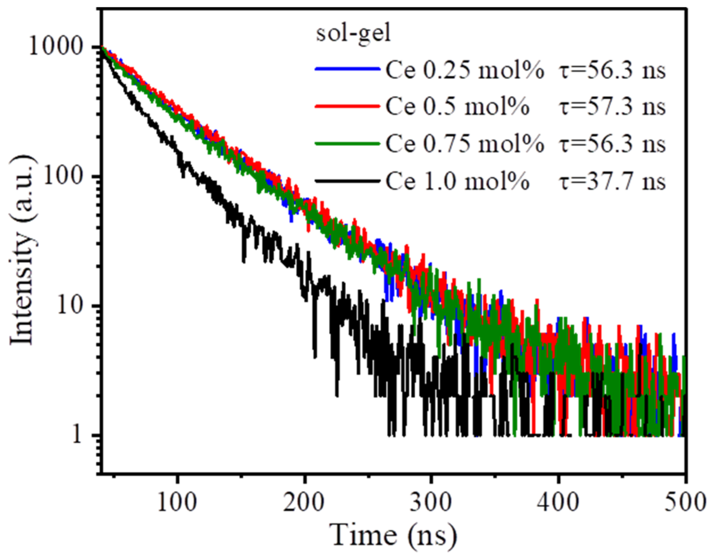
3.2.2. Fluorescence Lifetime Properties

The fluorescence lifetime of the sol-gel YAG: Ce powder was measured using the spectrofluorometer; a 460 nm laser with an excitation source of ps pulse was selected as the monitoring wavelength, and the test results are shown in Figure 8.
The resulting decay spectra can be fitted by Equation (3) to obtain the corresponding attenuation time.
I t = A exp t τ + B
where I represents the intensity of fluorescence, A is the initial amplitude, τ indicates the life of fluorescence, and B is a fit result of an order higher than two, which can be omitted. As seen from Figure 8, the fluorescence life of the YAG: Ce powder prepared by the sol-gel method belongs on the nanosecond level.
By comparing the trend of fluorescence lifetime and the trend of emission intensity in Figure 6 and Figure 8, both show that the Ce3+ concentration of 0.5 mol.% reaches maximum, and the maximum fluorescence lifetime of the sol-gel method YAG: Ce powder is 57.3 ns. Then, with the increase in Ce3+ concentration, the fluorescence lifetime showed a decreasing trend. After reaching the maximum, both the intensity of PL and the lifetime decreased, indicating the consistency between. The change is due to the time of energy conversion from the lattice to the luminescence center, which generally depends on the distance between the electron-hole pairs or the donor–acceptor pair, which is ultimately due to the intervention of the Ce3+ activator agent [39]. As the doping concentration of Ce3+ increases, the distance between the luminescent centers in the material becomes shorter, so the fluorescence life decreases, and the excitation molecules return to the ground state through other processes, such as quenching or energy transfer, which speed up the process of energy release from the excitation molecules, explaining why the luminescence lifetime of 1 mol.% is significantly reduced compared to other samples [40]. This conclusion confirms the theoretical speculation about the changes in emission peaks discussed in the previous section.

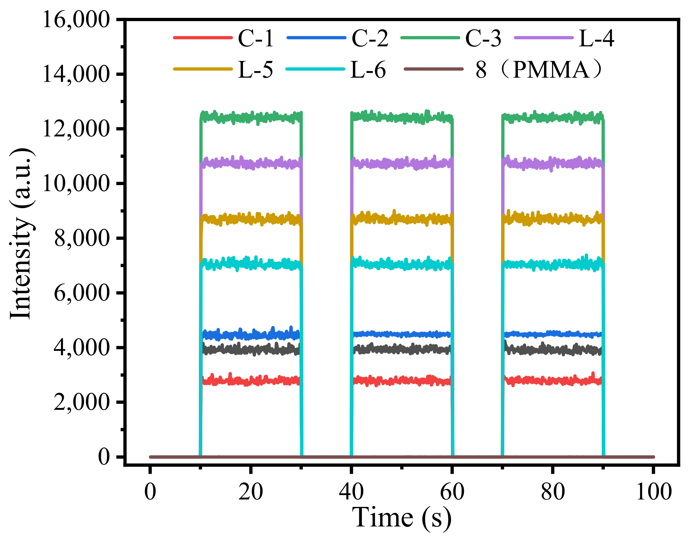
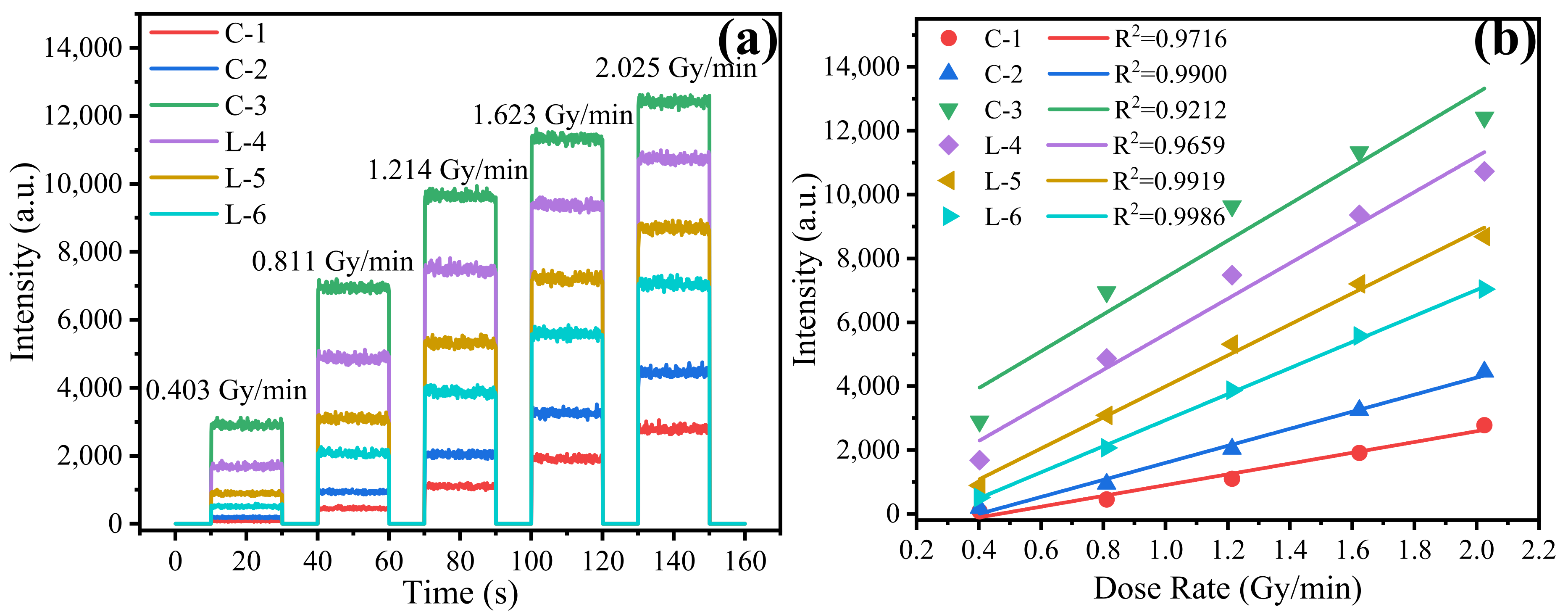
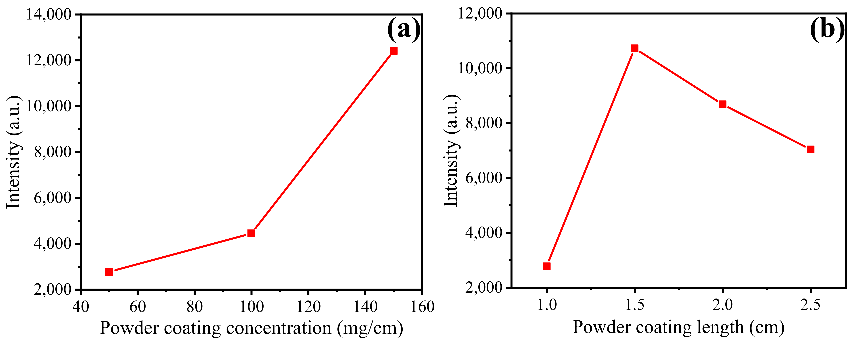
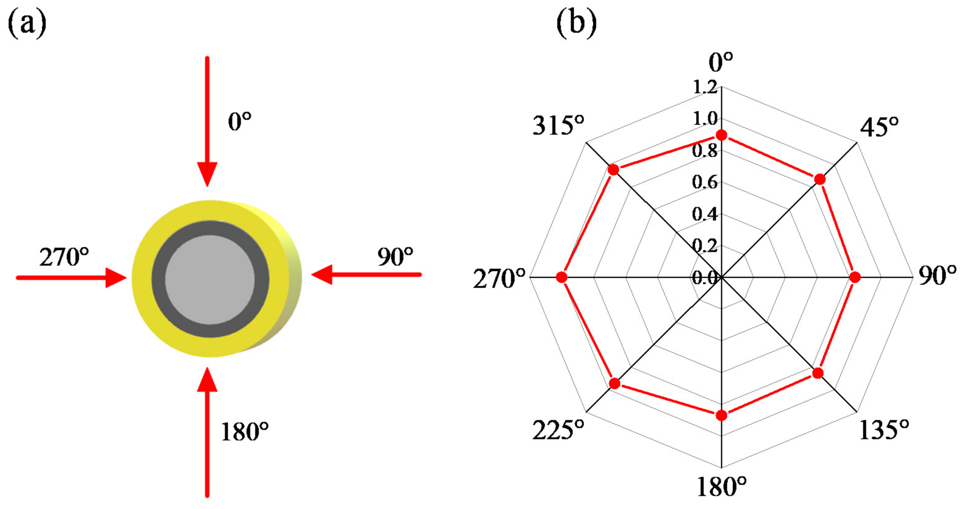
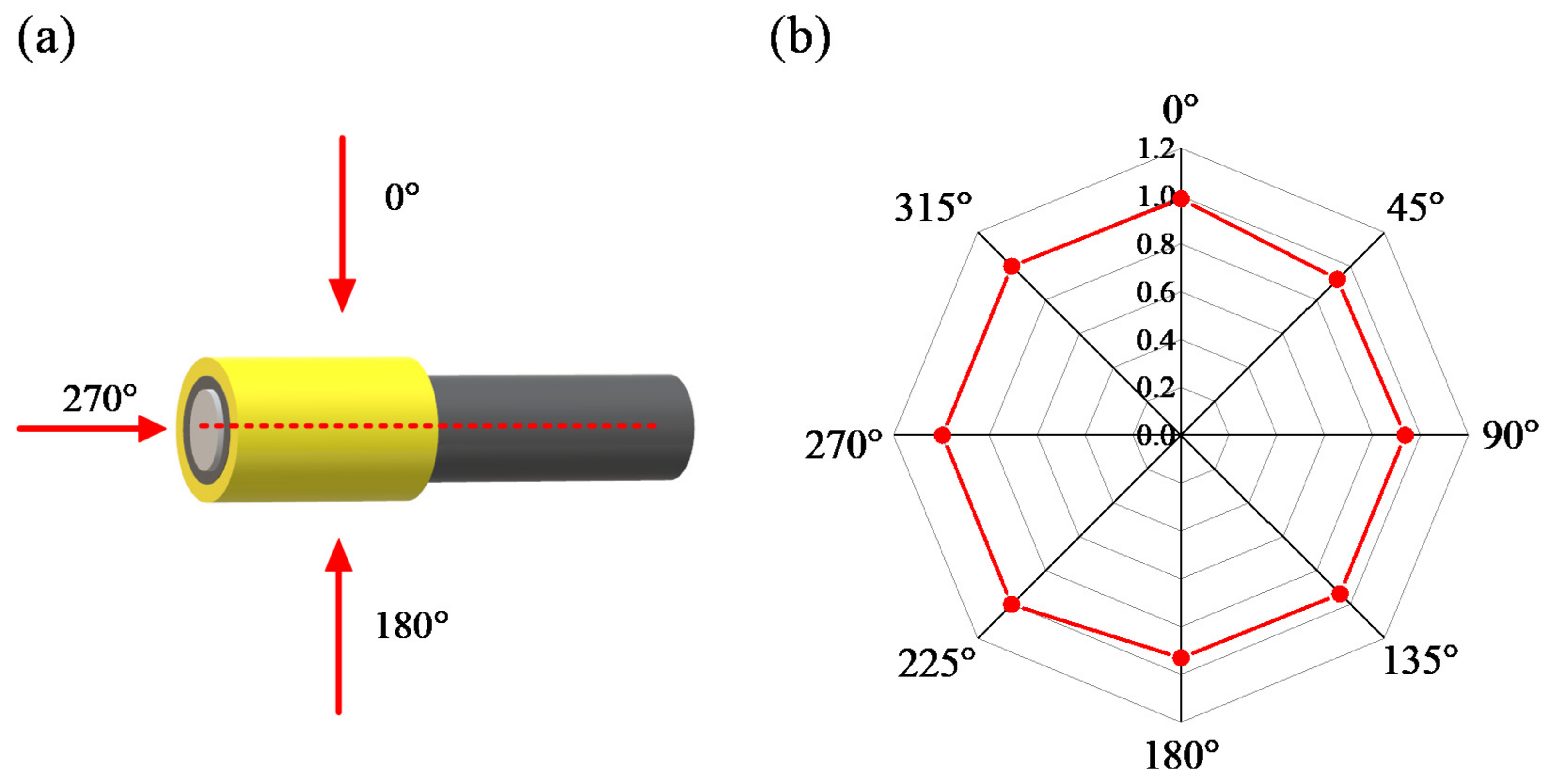
3.3. Radiation Sensing Characteristic

X-ray irradiation systems employed the MultiRad160 by Faxitron® (Tucson, AZ, USA) with a set energy of 60 kV and adjustable dose rate according to a separate experiment. The detection unit consisted of a photomultiplier tube (PMT) (CR105, Hamamatsu Photonics, Iwata, Japan) of a sampling frequency of 10 Hz, and a data acquisition card was sent to a computer.
For certain radiation sources, the parameters for radiation measurement are mainly the dose and dose rate, and whether these two parameters can be measured correctly and repeatable becomes the criteria of radiation dosimeter. The first thing to identify is whether the dosimeter is repeatable; we studied the RL response of the seven dosimeters prepared in Section 2.2; the parameters are listed in Table 1. We set the X-ray energy at 60 kV with dose rates of 2.025 Gy/min, and an irradiation time of 20 s per exposure, carried out several repeated experiments with seven dosimeters, and intercepted the RL response three times, as shown in Figure 9. Figure 9 shows that under the same irradiation conditions, the response of the RL signal produced by each dosimeter of repeat tests is basically level, indicating that the dosimeter prepared by coating YAG: Ce powder on PMMA can completely carry out radiation detection; with the sensitive monitoring unit, a rather flat waveform during irradiation was obtained. It was found that the C-3 response is much higher than that for other dosimeters. The dosimeter of C-3 has a relatively high YAG: Ce powder coating concentration, and it therefore has more luminescence centers; thus, a higher light yield is reached. Under the same coating length, C-1, C-2, and C-3 show a gradually increased signal intensity, indicating that the increase in coating concentration could lead to a higher luminous efficiency to a certain extent, whereas C-1, L-4, L-5, and L-6 have a fixed coating concentration and gradually increased the coating length. However, the response rose and then decreased, indicating that saturation was reached. Further increasing the length of the dosimeter will only result in a greater loss.
Through the uniform and stable performance of the curves in Figure 9, it is found that the cumulative value of the fluorescence intensity of each dosimeter is stable under the same radiation environment, which indicates that the YAG: Ce powder dosimeter has good stability and repeatability when monitoring the dose of X-ray radiation. At the same time, it also found that the background noise represented by dosimeter 8, i.e., the PMMA signal, compared with the response of the rest of the dosimeters, can be ignored. In the course of this experiment, the effect of the Cherenkov effect does not need to be considered; compared with the application of the radiation dosimeter under radiation sources of higher energy, the source of this paper is rather weak, and low energy and strong closure during radiation makes it less influenced. Subsequent experiments will show signals that have removed the radiation background signal of dosimeter-8.
The RL response of the dosimeter at differently irradiated dose rates of 0.403 Gy/min, 0.811 Gy/min, 1.214 Gy/min, 1.623 Gy/min, and 2.025 Gy/min was studied under the same test conditions. RL responses for six dosimeters are shown in Figure 10a. As can be seen from the figure, the signal intensity comparison of dosimeters at each radiation dose rate is consistent with the results of repetitive measurements, and when the given dose rate is altered from low to high, the real time RL response of all dosimeters increases. The mean value of RL response under certain dose rates was taken as the RL response at that dose rate, and the relationship between the radiation dose rate and the response of the six dosimeters was linearly regressed in Figure 10b.
The results of Figure 10b show a linear relationship between the RL response of the dosimeter and the dose rate of X-rays, in which the growth of C-3, L-4, and L-5 dosimeters’ signal decreases with the increase in the X-ray dose rate, which appears to exhibit a “staying” phenomenon. This may be due to the YAG: Ce coating concentration being too high or coated too long, affecting signal propagation into the PMMA; thus, even though the dose rate increases, or more luminescent centers are activated and release stronger fluorescence, only a certain amount of fluorescence transmitted to PMMA to form an optical waveguide can be monitored by the PMT. It is therefore assumed that the coating concentration being too high or the coating length being too long will limit the dosimeter’s ability to monitor the linear range of the radiation dose rate, as shown in Figure 11.
Figure 11 compares the RL response of different dosimeters of YAG: Ce powder coating concentrations and coating length. Figure 11a shows that the concentration of the dosimeter powder coating is positively correlated with the RL response of dosimeters within the range of powder coating concentration in this experiment. Figure 11b compares the RL response and coating length, and the results show that under the condition of fixed powder coating concentration, the appropriate increase in powder coating length can improve the RL response. However, longer may not be better; because the resulting fluorescence is transmitted to PMMA through the epoxy resin and powder-mixing medium, the longer sensing probe affects the fluorescence propagating to PMMA, whereas the dosimeter-sensing part should be shorter than the requirements of clinical radiation monitoring dosimeter miniaturization. This analysis is consistent with the conclusion reached by Figure 10b. Although we have proven that the Cherenkov effect is negligible, when it comes to a source with higher energies, it should be taken into consideration in further studies.
The variation in response as a function of the angle of the incidence of the radiation is called the directional dependence of a dosimeter [19,41,42]. It is an important to evaluate the performance of a radiation dosimeter; commercial dosimeters’ directional dependence is due to their composition, physical shape, production, and practical application. The previous section on the X-ray measurement of repeatability and different dose rate response characteristics based on the study determined the availability of the dosimeter; this is followed by the verification of the angle dependence of the dosimeter, taking the most sensitive C-3 dosimeter to show the effect of the angle to the greatest extent.
In the radial angle dependence experiment shown in Figure 12, the X-ray irradiator was set to have an irradiate energy of 60 kV and a dose rate of 2.025 Gy/min, with a duration of 20 s, and the dosimeter was rotated clockwise, as shown in Figure 12a. After normalizing the cumulative values of the various angles of fluorescence intensity detected by the dosimeter, the radical dependence radar diagram is shown in Figure 12b. It was found that the RL response decreased slightly from 270 degrees clockwise to 90 degrees and gradually increased from 90 degrees clockwise to 270 degrees of strength, showing certain symmetry, presumably due to an immature preparation process, since the powder and epoxy mixture coating around the PMMA takes a certain amount of time, during which the crystal powder should be deposited evenly, suggesting an inclination during the process that results in the uneven distribution of powder.
Axial angle dependence experiments are similar, and the dependence is available in Figure 13; the X-ray source settings remained unchanged, the angles of X-rays and dosimeters were set at 0, 45, 90, 135, 180, 225, 270, and 315 degrees, and the cumulative values of fluorescence intensity were normalized to obtain the results shown in Figure 13b. At angles of 225, 270, 315, and 0 degrees, the intensity is larger than that at other points, and the reasons for the deviation of angle dependence under rotation conditions may be due to the fiber adapter, flanges, and transmission fibers connected to the dosimeter and transmission fiber having a certain occlusion to the X-ray source when testing from 45 degrees clockwise to 135 degrees. Fluorescent materials were coated on the surface of PMMA fiber, and the fluorescence generated by X-ray irradiation excitation at this angle has a greater scattering loss to the transmission fiber, resulting in a decrease in the cumulative value of fluorescence intensity; it can also be seen that the fluorescence intensity is inconsistent at 0 and 180 degrees. The reason for this may be consistent with the reason for the deviation of the radial-angle dependence, because the crystal powder in the dosimeter is not evenly distributed radially around the PMMA.
Through the comparison of the above two experiments, we found that the method of preparing the YAG: Ce powder dosimeter has a certain angle dependence, which is related to the preparation process. In subsequent studies, preparation dosage and timing should ensure the uniformity of material coating or embedding to reduce the effect of the angle. Similarly, in the case of scintillating fiber preparation, the YAG: Ce powder is injected into the quartz casing, which is concentrated by an ultrasonic bath shock, and the powder casing is used to prepare quartz fiber; however, in previous studies [20], it is shown that the fiber core layer prepared in this way is not uniform and the core is not a perfect circle, which will certainly affect the light waveguide, and the fluorescence effect will not be good, so the method of this paper brings some improvement. However, with the improvement of the drawing techniques, the radiation sensing effect of crystal fiber is promising.

4. Discussion and Conclusion

In this paper, YAG: Ce powder with four concentration gradients was prepared by the sol-gel method for online radiation sensing. After exploring the microcharacteristics and optical properties of such materials, we found that the ideal doping concentration suitable for radiation-sensing purposes is 0.5 mol.%. Six radiation dosimeters were prepared to detect the dose and dose rate parameters of X-ray radiation and their reliability and accuracy.
Through XRD and SEM patterns, it was speculated and verified that the fluorescent powder prepared by the sol-gel legal system method produced a complete phase of YAG: Ce structure with a nanoscale particle size, and the effect of doping on the fluorescence efficiency of the sample was found through the study of its fluorescence properties. The doping concentration of the sample of 0.5 mol.% shows a relatively high emission spectrum and long fluorescence life (57 ns).
By considering the parameters of dose and dose rate under actual radiation conditions under the same dose rate, we obtained the conclusion of good repeatability; a changing dose rate shows the rise of step-by-step accumulation, which shows good sensitivity, and the verification that each dosimeter can work repeatably under continuous irradiation; that is, prepared dosimeters have good stability and reliability. Additionally, we summarized the influence of coating concentration and length on the RL response under comprehensive consideration of their application. Likewise, experimental control proved that the Cherenkov effect could be ignored, and its angle dependence is considered for subsequent improvement.
Although the feasibility of the dosimeter was verified by the experiment in this paper, more research on the continuous measurement of X-rays with higher energy and dose rates under more complex and uncontrollable radiation compositions is needed for further consideration.

Author Contributions

Y.Y. coordinated the study of materials and wrote the main part of the manuscript; C.Z. participated in validation of experiments; L.Z. and T.W. contributed in dosimeter preparation; M.L. reviewed and edited the manuscript; F.X. participated in investigation; G.P. contributed in methodology, and Q.G. was in charge of supervision and project administration. All authors have read and agreed to the published version of the manuscript.

Funding

This research was funded by Higher Education Discipline Innovation Project of China, grant number D20031.

Data Availability Statement

Data are available from the corresponding author on request.

Conflicts of Interest

The authors declare no conflict of interest.

References

  1. Nikl, M. Scintillation detectors for X-rays. Meas. Sci. Technol. 2006, 17, R37–R54. [Google Scholar] [CrossRef]
  2. Skaane, P.; Bandos, A.I.; Gullien, R.; Eben, E.B.; Ekseth, U.; Haakenaasen, U.; Izadi, M.; Jebsen, I.N.; Jahr, G.; Krager, M.; et al. Comparison of digital mammography alone and digital mammography plus tomosynthesis in a population-based screening program. Radiology 2013, 267, 47–56. [Google Scholar] [CrossRef] [PubMed] [Green Version]
  3. Lee, Y.; Hara, T.; Fujita, H.; Itoh, S.; Ishigaki, T. Automated detection of pulmonary nodules in helical CT images based on an improved template-matching technique. IEEE Trans. Med. Imaging 2001, 20, 595–604. [Google Scholar] [CrossRef] [PubMed]
  4. Mones, E.; Veronese, I.; Moretti, F.; Fasoli, M.; Loi, G.; Negri, E.; Brambilla, M.; Chiodini, N.; Brambilla, G.; Vedda, A. Feasibility study for the use of Ce3+-doped optical fibres in radiotherapy. Nucl. Instrum. Methods Phys. Res. Sect. A Accel. Spectrometers Detect. Assoc. Equip. 2006, 562, 449–455. [Google Scholar] [CrossRef]
  5. Siva, S.; MacManus, M.P.; Martin, R.F.; Martin, O.A. Abscopal effects of radiation therapy: A clinical review for the radiobiologist. Cancer Lett. 2015, 356, 82–90. [Google Scholar] [CrossRef] [PubMed]
  6. Qin, Z.; Xie, T.; Dai, X.; Zhang, B.; Ma, Y.; Khan, I.U.; Zhang, X.; Li, H.; Yan, Y.; Zhao, W.; et al. New model for explaining the over-response phenomenon in percentage of depth dose curve measured using inorganic scintillating materials for optical fiber radiation sensors. Opt. Express 2019, 27, 23693–23706. [Google Scholar] [CrossRef] [PubMed]
  7. Prasanna, P.G.; Woloschak, G.E.; DiCarlo, A.L.; Buchsbaum, J.C.; Schaue, D.; Chakravarti, A.; Cucinotta, F.A.; Formenti, S.C.; Guha, C.; Hu, D.J.; et al. Low-Dose Radiation Therapy (LDRT) for COVID-19: Benefits or Risks? Radiat. Res. 2020, 194, 452–464. [Google Scholar] [CrossRef] [PubMed]
  8. Girard, S.; Kuhnhenn, J.; Gusarov, A.; Brichard, B.; van Uffelen, M.; Ouerdane, Y.; Boukenter, A.; Marcandella, C. Radiation Effects on Silica-Based Optical Fibers: Recent Advances and Future Challenges. IEEE Trans. Nucl. Sci. 2013, 60, 2015–2036. [Google Scholar] [CrossRef]
  9. Adhikari, R.X. Gravitational radiation detection with laser interferometry. Rev. Mod. Phys. 2014, 86, 121–151. [Google Scholar] [CrossRef]
  10. Almond, P.R.; Svensson, H. Ionization chamber dosimetry for photon and electron beams. Acta Radiol. Ther. Phys. Biol. 1977, 16, 177–186. [Google Scholar] [CrossRef] [PubMed]
  11. Knoll, G.F. Radiation Detection and Measurement. Proc. IEEE 2010, 69, 495. [Google Scholar]
  12. Robar, J.L.; Clark, B.G. The use of radiographic film for linear accelerator stereotactic radiosurgical dosimetry. Med. Phys. 1999, 26, 2144–2150. [Google Scholar] [CrossRef]
  13. Martens, C.; Claeys, I.; Wagter, C.D.; Neve, W.D. The value of radiographic film for the characterization of intensity-modulated beams. Phys. Med. Biol. 2002, 47, 2221–2234. [Google Scholar] [CrossRef] [PubMed]
  14. Rikner, G.; Grusell, E.; Kostjuchenko, V.; Lukjashin, V.; Lomanov, M. Radiation damage and dose rate linearity response of a p-Si detector in 70 MeV protons. Nucl. Instrum. Methods Phys. Res. A 1983, 217, 501–505. [Google Scholar] [CrossRef]
  15. Srinivasan, V.S.S.; Pandya, A. Dosimetry aspects of hafnium oxide metal-oxide-semiconductor (MOS) capacitor. Thin Solid Films 2011, 520, 574–577. [Google Scholar] [CrossRef]
  16. Veronese, I.; Chiodini, N.; Cialdi, S.; d’Ippolito, E.; Fasoli, M.; Gallo, S.; La Torre, S.; Mones, E.; Vedda, A.; Loi, G. Real-time dosimetry with Yb-doped silica optical fibres. Phys. Med. Biol. 2017, 62, 4218–4236. [Google Scholar] [CrossRef] [PubMed]
  17. Payne, S.A.; James, R.B.; Franks, L.; Burger, A.; Fiederle, M.; Loi, G.; Vedda, A.; Mones, E.; Fasoli, M.; D’Ippolito, E.; et al. Characterization of Yb-doped silica optical fiber as real-time dosimeter. In Hard X-ray, Gamma-Ray, and Neutron Detector Physics XIX; SPIE: San Diego, CA, USA, 2017. [Google Scholar]
  18. Savard, N.; Potkins, D.; Beaudry, J.; Jirasek, A.; Duzenli, C.; Hoehr, C. Characteristics of a Ce-Doped silica fiber irradiated by 74 MeV protons. Radiat. Meas. 2018, 114, 19–24. [Google Scholar] [CrossRef]
  19. Yoo, W.J.; Shin, S.H.; Jeon, D.; Hong, S.; Kim, S.G.; Sim, H.I.; Jang, K.W.; Cho, S.; Lee, B. Simultaneous measurements of pure scintillation and Cerenkov signals in an integrated fiber-optic dosimeter for electron beam therapy dosimetry. Opt. Express 2013, 21, 27770–27779. [Google Scholar] [CrossRef]
  20. Vedda, A.; Chiodini, N.; Di Martino, D.; Fasoli, M.; Keffer, S.; Lauria, A.; Martini, M.; Moretti, F.; Spinolo, G.; Nikl, M.; et al. Ce3+-doped fibers for remote radiation dosimetry. Appl. Phys. Lett. 2004, 85, 6356–6358. [Google Scholar] [CrossRef]
  21. Girard, S.; Ouerdane, Y.; Marcandella, C.; Boukenter, A.; Quenard, S.; Authier, N. Feasibility of radiation dosimetry with phosphorus-doped optical fibers in the ultraviolet and visible domain. J. Non-Cryst. Solids 2011, 357, 1871–1874. [Google Scholar] [CrossRef]
  22. Chen, W.Q.; Jo, D.S.; Song, Y.H.; Masaki, T.; Yoon, D.H. Synthesis and photoluminescence properties of YAG: Ce3+ phosphor using a liquid-phase precursor method. J. Lumin. 2014, 147, 304–309. [Google Scholar] [CrossRef]
  23. Saat, A.; Harun, A.; Hamzah, Z. Synthesis and characterization of YAG: Ce prepared by solid state reaction method. Malays. J. Anal. Sci. 2011, 15, 101–1050. [Google Scholar]
  24. You, Z.; Yue, K.; Zhang, J.; Ke, P.; Gu, D.; Guo, Q.; Luo, W. Effects of atmosphere and temperature on luminescence property of YAG: Ce synthesized by co-precipitation method. Optik 2019, 176, 241–245. [Google Scholar] [CrossRef]
  25. Zhang, L.; Lu, Z.; Zhu, J.; Yang, H.; Han, P.; Chen, Y.; Zhang, Q. Citrate sol-gel combustion preparation and photoluminescence properties of YAG: Ce phosphors. J. Rare Earths 2012, 30, 289–296. [Google Scholar] [CrossRef]
  26. Guo, Q.; Li, M.; Yue, K.; Yan, Y.; Xie, F.; Zhang, C.; Mou, C.; Peng, G.D. Characterization of YAG: Ce phosphor dosimeter by the co-precipitation method for radiotherapy. Appl. Opt. 2021, 60, 3044–3048. [Google Scholar] [CrossRef]
  27. Guo, Q.; Li, M.; Gu, D.; Yan, Y.; Yue, K.; Xie, F.; Zhang, C.; Mou, C.; Peng, G.-D.; Wang, T. Luminescence characterizations of YAG: Ce crystal via sol-gel method for radiotherapy. Opt. Mater. 2020, 109, 110297. [Google Scholar] [CrossRef]
  28. Drits, V.; Środoń, J.; Eberl, D.D. XRD Measurement of Mean Crystallite Thickness of Illite and Illite/Smectite: Reappraisal of the Kubler Index and the Scherrer Equation. Clays Clay Miner. 1997, 45, 461–475. [Google Scholar] [CrossRef]
  29. Zhang, Z.; Zhou, F.; Lavernia, E.J. On the analysis of grain size in bulk nanocrystalline materials via X-ray diffraction. Metall. Mater. Trans. A 2003, 34, 1349–1355. [Google Scholar] [CrossRef]
  30. Goonewardene, A.; Guo, X.; Guo, X.Z.; Jia, D.; Jia, W.; Li, K.K.; Shaffer, C.V.; Wang, Y.; Weyant, J.E.; Zou, Y.K. YAG: Ce3+ Nanophosphor Synthesized with Salted Sol-Gel Method. In Proceedings of the 2006 NSTI Nanotechnology Conference and Trade Show, Boston, MA, USA, 7–11 May 2006; Volume 1, pp. 339–342. [Google Scholar]
  31. Rai, P.; Song, M.-K.; Song, H.-M.; Kim, J.-H.; Kim, Y.-S.; Lee, I.-H.; Yu, Y.-T. Synthesis, growth mechanism and photoluminescence of monodispersed cubic shape Ce doped YAG nanophosphor. Ceram. Int. 2012, 38, 235–242. [Google Scholar] [CrossRef]
  32. He, X.; Liu, X.; Li, R.; Yang, B.; Yu, K.; Zeng, M.; Yu, R. Effects of local structure of Ce(3+) ions on luminescent properties of Y3Al5O12: Ce nanoparticles. Sci. Rep. 2016, 6, 22238. [Google Scholar] [CrossRef] [PubMed] [Green Version]
  33. Lee, Y.-W.; Wu, S.-H. Fabrication and performance assessment of coprecipitation-based YAG: Ce nanopowders for white LEDs. Microelectron. Eng. 2018, 199, 24–30. [Google Scholar] [CrossRef]
  34. Veith, M.; Mathur, S.; Kareiva, A.; Jilavi, M.; Zimmer, M.; Huch, V. Low temperature synthesis of nanocrystalline Y3Al5O12 (YAG) and Ce-doped Y3Al5O12via different sol–gel methods. J. Mater. Chem. 1999, 9, 3069–3079. [Google Scholar] [CrossRef]
  35. Jacobs, R.R.; Krupke, W.F.; Weber, M.J. Measurement of excited-state-absorption loss for Ce3+ in Y3Al5O12 and implications for tunable 5d→4f rare-earth lasers. Appl. Phys. Lett. 1978, 33, 410–412. [Google Scholar] [CrossRef]
  36. Huang, S.H.; Lou, L.R. Concentration dependence of sensitizer fluorescence intensity in energy transfer. Chin. J. Lumin 1990, 11, 1–7. [Google Scholar]
  37. Dai, Q.; Song, H.; Wang, M.; Bai, X.; Zhang, H. Size and Concentration Effects on the Photoluminescence of La2O2S: Eu3+ Nanocrystals. J. Phys. Chem. C 2008, 112, 19399–19404. [Google Scholar] [CrossRef]
  38. Dexter, D.L.; Schulman, J.H. Theory of Concentration Quenching in Inorganic Phosphors. J. Chem. Phys. 1954, 22, 1063–1070. [Google Scholar] [CrossRef]
  39. Lisitsyn, V.; Lisitsyna, L.; Tulegenova, A.; Ju, Y.; Polisadova, E.; Lipatov, E.; Vaganov, V. Nanodefects in YAG: Ce-Based Phosphor Microcrystals. Crystals 2019, 9, 476. [Google Scholar] [CrossRef] [Green Version]
  40. Gorbenko, V.; Zorenko, T.; Witkiewicz-Łukaszek, S.; Shakhno, A.; Osvet, A.; Batentschuk, M.; Fedorov, A.; Zorenko, Y. Crystallization and Investigation of the Structural and Optical Properties of Ce3+-Doped Y3−xCaxAl5−ySiyO12 Single Crystalline Film Phosphors. Crystals 2021, 11, 788. [Google Scholar] [CrossRef]
  41. Suchowerska, N.; Hoban, P.; Butson, M.; Davison, A.; Metcalfe, P. Directional dependence in film dosimetry: Radiographic and radiochromic film. Phys. Med. Biol. 2001, 46, 1391–1397. [Google Scholar] [CrossRef] [PubMed]
  42. Hosokai, Y.; Matsumoto, K.; Kozakai, M.; Takahashi, K.; Usui, A.; Win, T.P.; Muroi, K.; Saito, H. Development of Real-Time Radiation Exposure Dosimetry System Using Synthetic Ruby for Interventional Radiology. Radiat. Prot. Dosim. 2017, 175, 517–522. [Google Scholar] [CrossRef]
Figure 1. Eight YAG: Ce dosimeters with different parameters were made with the physical graph shown on the right side. On the left side are phosphors prepared via the sol-gel method; the color deepened as the concentration of Ce became higher; from top to bottom are YAG: Ce powders with Ce concentration of 0.25 mol.%, 0.5 mol.%, 0.75 mol.%, and 1 mol.%.
Crystals 11 01567 g001
Figure 2. The schematic diagram of the sensing experimental setup; inside the dashed line box, the composition of the dosimeter is shown, where the yellow part represents the YAG: Ce powder and the gray part refers to the PMMA fiber.
Crystals 11 01567 g002
Figure 3. XRD patterns of samples synthesized under four sintering temperatures by the sol-gel method grown in an inert atmosphere with nominal content pattern.
Crystals 11 01567 g003
Figure 4. SEM patterns of samples with four coping concentrations with magnification ×30,000. (a) 0.25 mol.% Ce doping (b) 0.5 mol.% Ce doping (c) 0.75 mol.% Ce doping (d) 1 mol.% Ce doping. Corresponding physical map in the lower-left corner.
Crystals 11 01567 g004
Figure 5. PL spectra of sample doped with 0.5 mol.% Ce grown in inert atmosphere; solid purple line is excitation with monitoring at 550 nm; solid red line and solid black line are emissions with excitation at 460 and 340 nm, respectively; dashed blue lines represent the Gauss decomposition of 460 nm emission peak, which corresponds to the transition of Ce3+.
Crystals 11 01567 g005
Figure 6. PL spectra with excitation at 460 nm of sol-gel samples with four concentrations under an inert atmosphere and sintering temperature of 1400 °C.
Crystals 11 01567 g006
Figure 7. YAG: Ce powder luminous intensity and activator concentration.
Crystals 11 01567 g007
Figure 8. Kinetics of photoluminescence (PL) decay.
Crystals 11 01567 g008
Figure 9. Dose–response of dosimeter, RL levels of the dosimeter with a different formation. The PMMA signal is faint and marked with ochre acting as the background signal.
Crystals 11 01567 g009
Figure 10. Radiation characteristic of dosimeters. (a) Dose rate response of dosimeter, RL levels of the dosimeter with a different formation; (b) relationship between signal intensity response and dose rate of powder dosimeters under different X-ray radiation dose rates.
Crystals 11 01567 g010
Figure 11. Effect of coating. (a) Comparison between coating concentration and signal intensity; (b) comparison between coating length and signal intensity.
Crystals 11 01567 g011
Figure 12. Radial-angle-dependence response of dosimeter. (a) schematic diagram; (b) radar chart of radial-angle dependence.
Crystals 11 01567 g012
Figure 13. Axial-angle-dependence response of dosimeter. (a) schematic diagram; (b), radar chart of axial-angle dependence.
Crystals 11 01567 g013
Table 1. Parameters of 7 dosimeters with a separate coating case, except for the last PMMA set as a control group; the method is sol-gel and a coping concentration of Ce3+ is 0.5 mol.%.
No.MaterialMethod Concentration (mg/cm)Length (cm)Diameter (mm)
C-1YAG: Cesol-gel5011.5
C-2YAG: Cesol-gel10011.5
C-3YAG: Cesol-gel15011.5
L-4YAG: Cesol-gel501.51.5
L-5YAG: Cesol-gel5021.5
L-6YAG: Cesol-gel502.51.5
8PMMAcommercial//1
Table 2. Estimated size of sol-gel samples with different concentrations of Ce3+.
MaterialMethodAtmosphereTemperature (°C)Grain Size (nm)
YAG: Cesol-gelnitrogen110073.8
YAG: Cesol-gelnitrogen120064.5
YAG: Cesol-gelnitrogen130070.1
YAG: Cesol-gelnitrogen140057.3
Publisher’s Note: MDPI stays neutral with regard to jurisdictional claims in published maps and institutional affiliations.

