
In Situ Investigations on Stress and Microstructure Evolution in Polycrystalline Ti(C,N)/α-Al2O3 CVD Coatings under Thermal Cycling Loads


 ,
,
Abstract
:
1. Introduction
2. Materials and Methods
2.1. Samples
2.2. Residual Stress Analysis in the Coating Layers
2.3. Microstrain and Domain Analysis
2.4. Microstructure Characterization
3. Results and Discussion
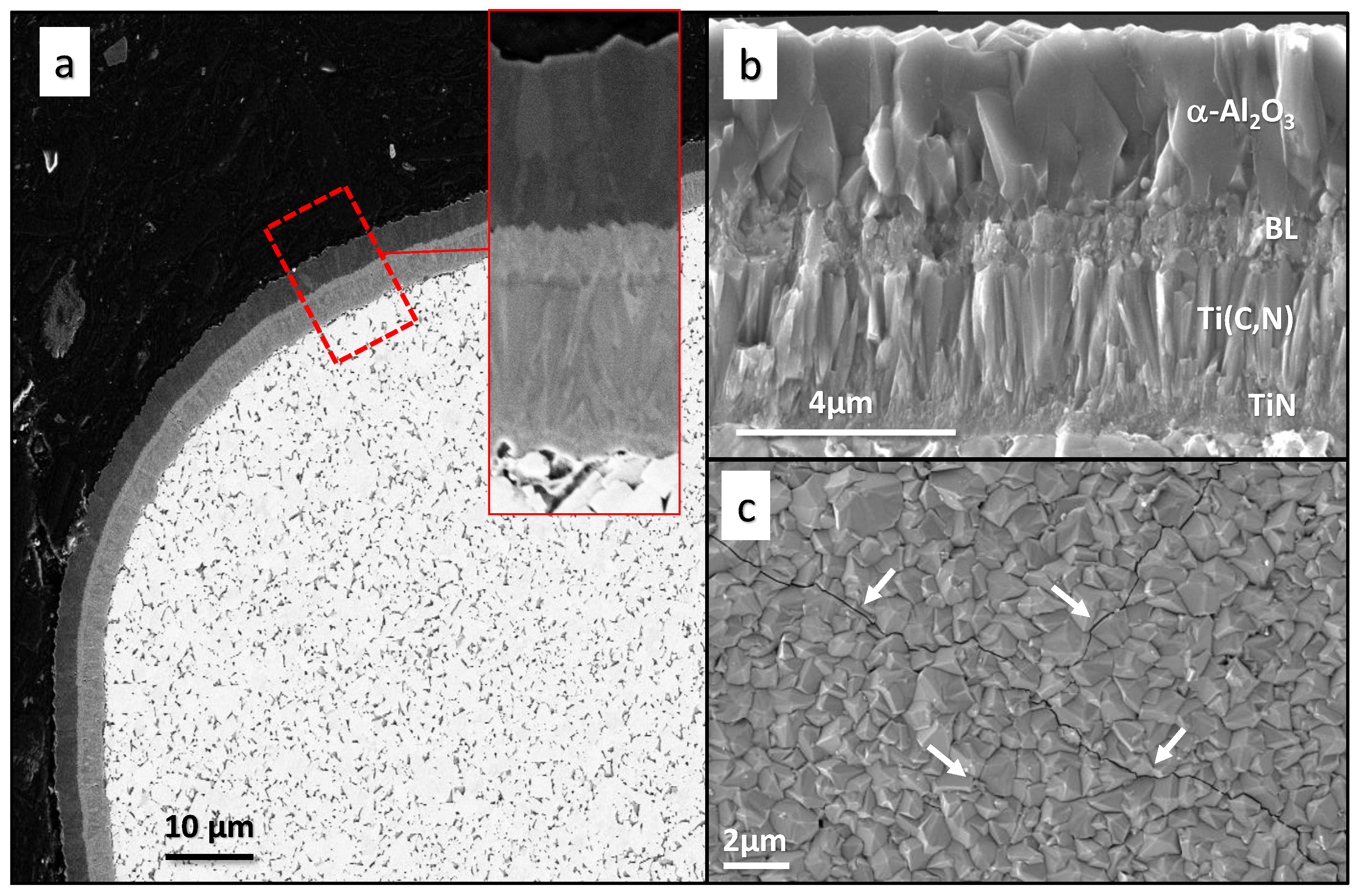
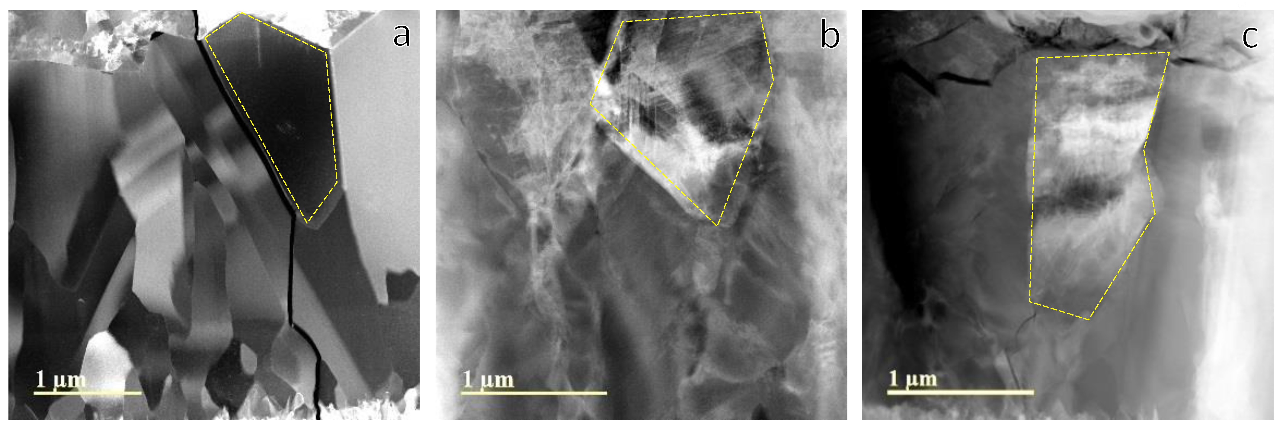
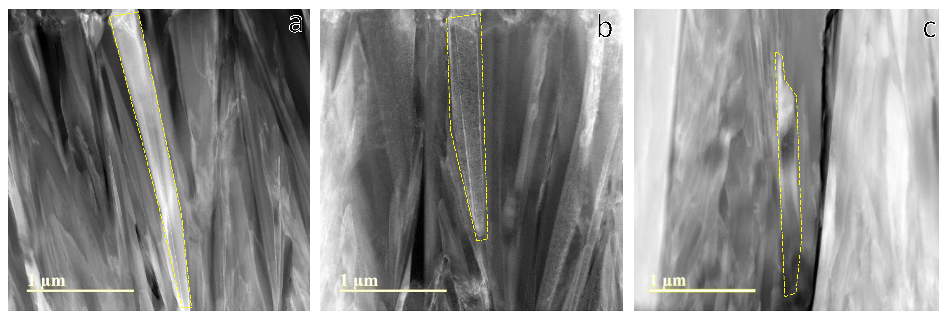
3.1. SEM Microstructure Analysis
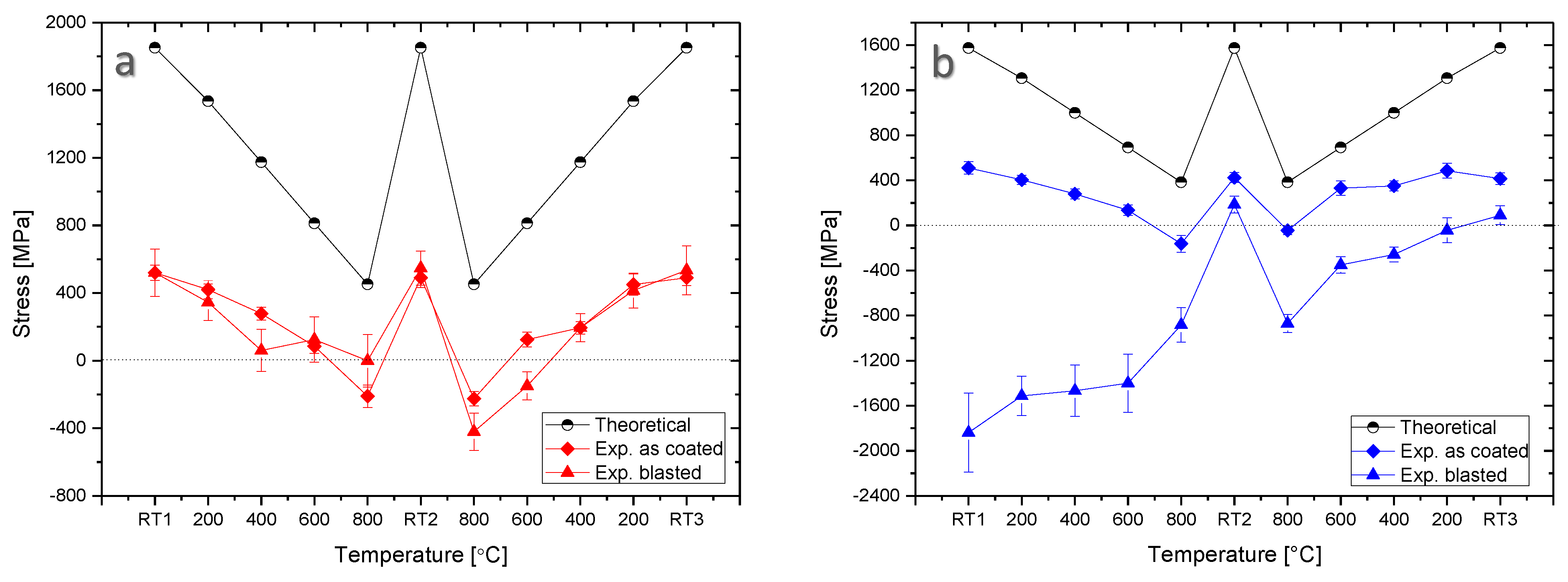
3.2. Synchrotron X-ray Stress Analysis
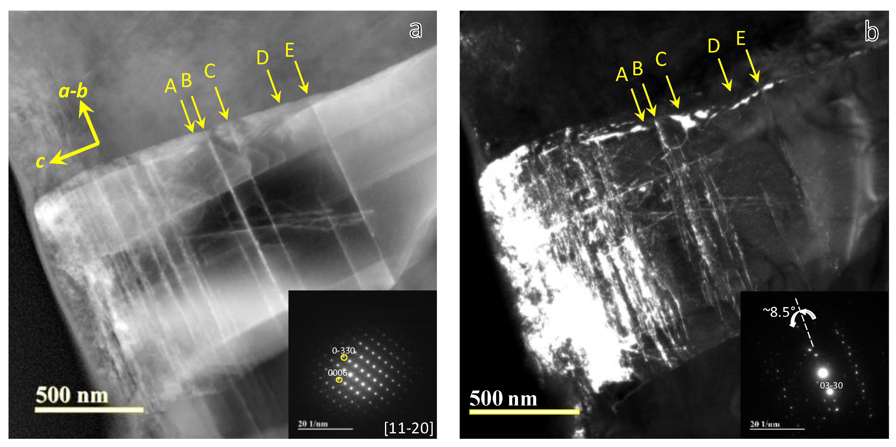
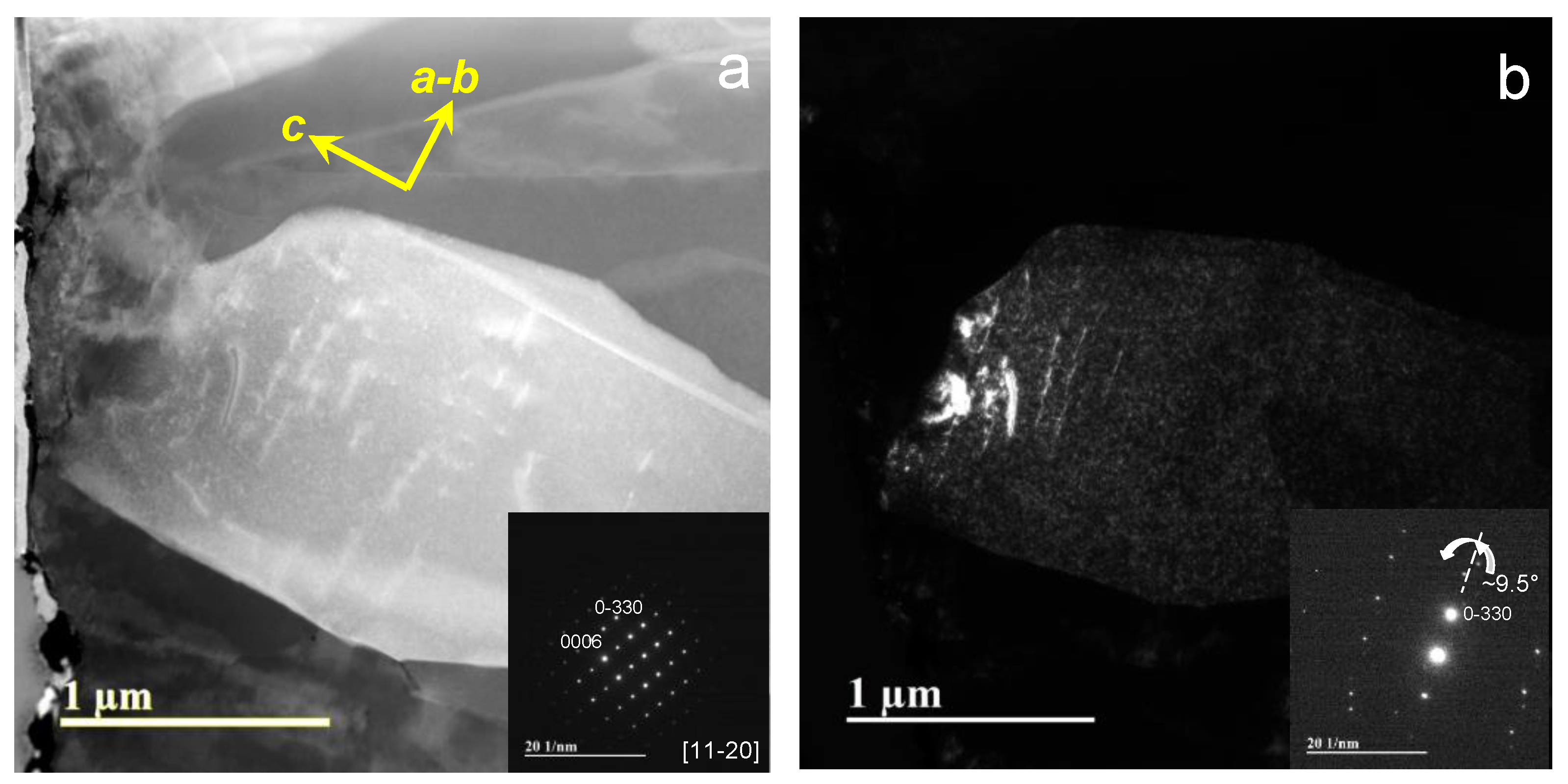
3.3. TEM and XRD Microstructure Analysis
4. Conclusions
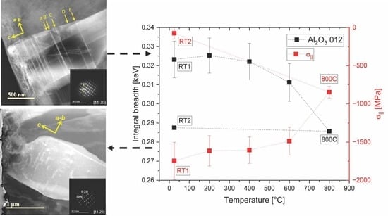
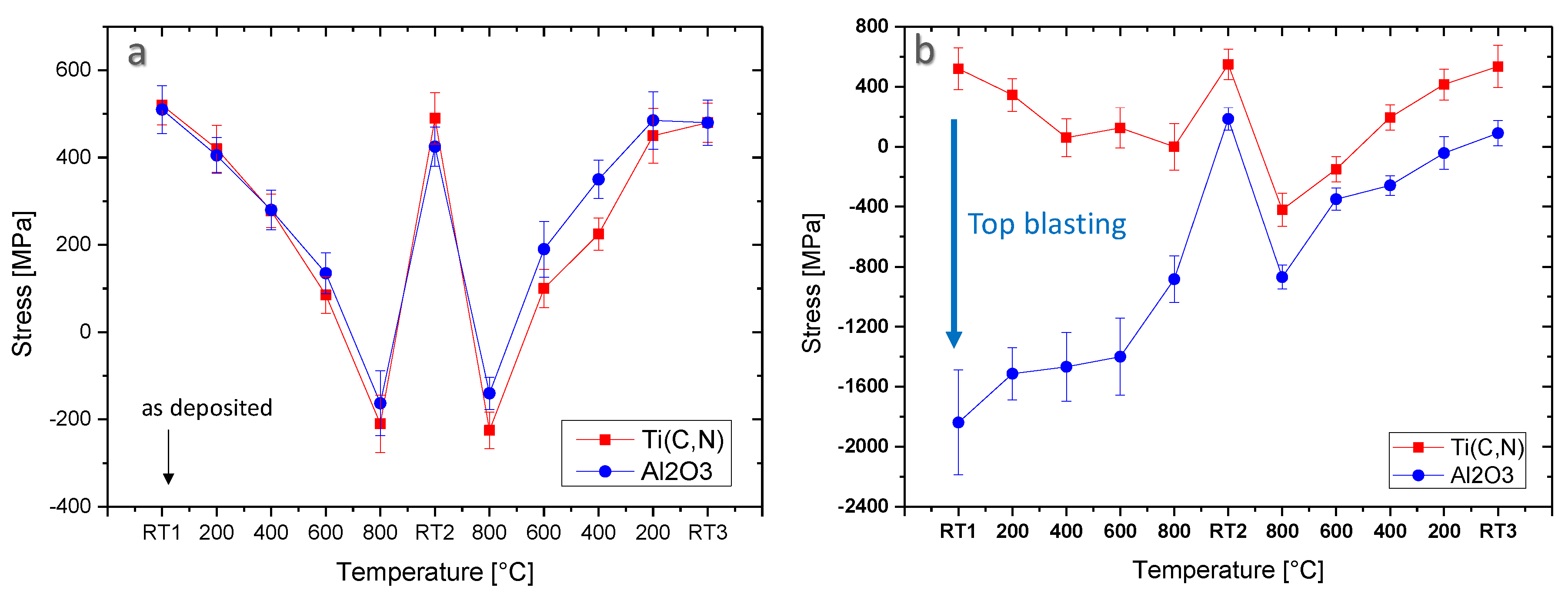
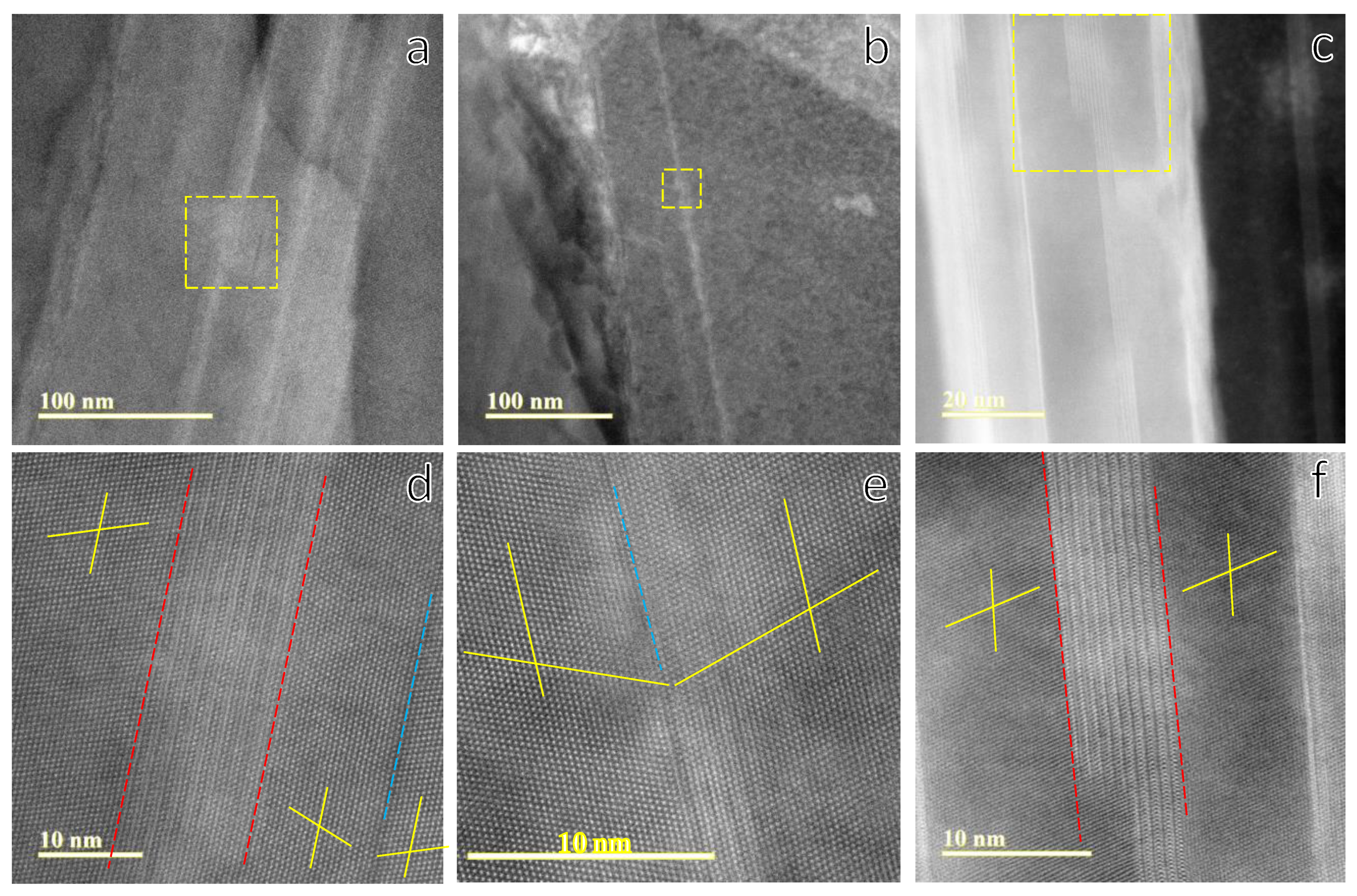
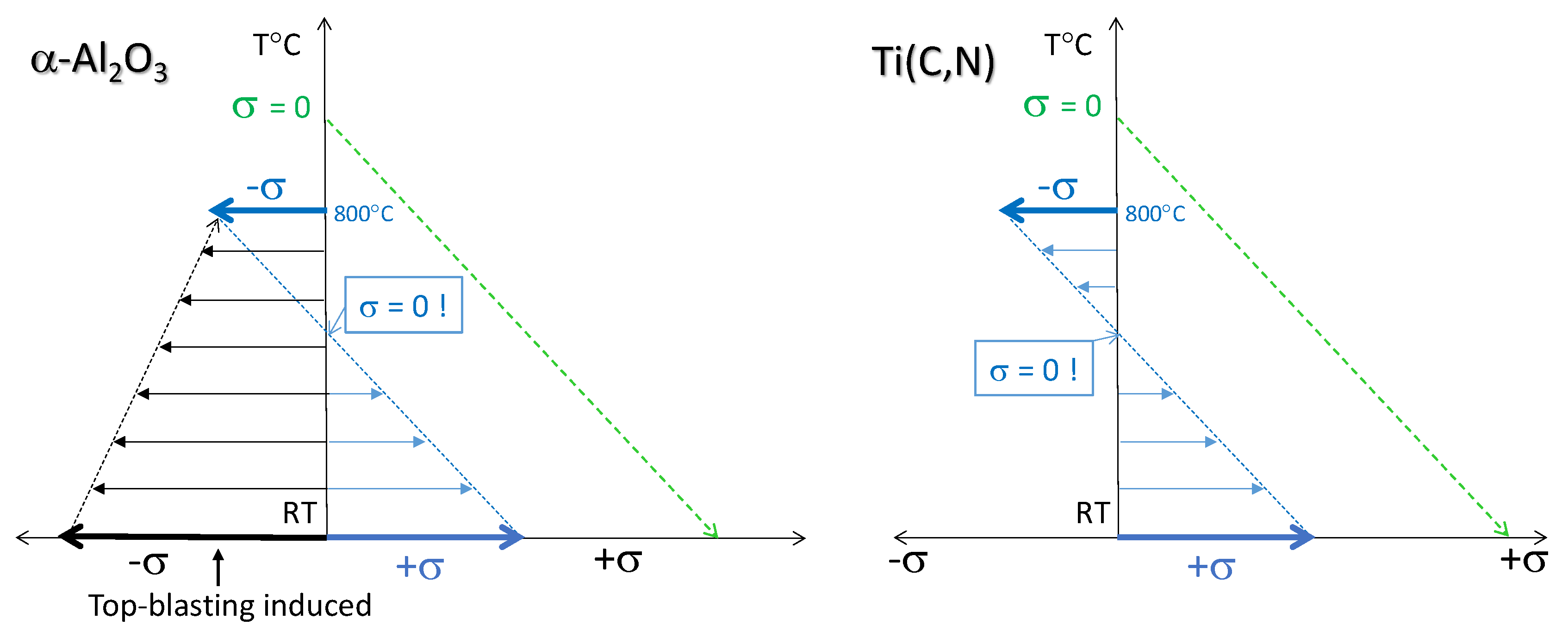
- The introduction of high compressive stresses in α-Al2O3 by top-blasting is connected to a high defect density at the basal planes of the alumina layer, as shown in the TEM image analysis.
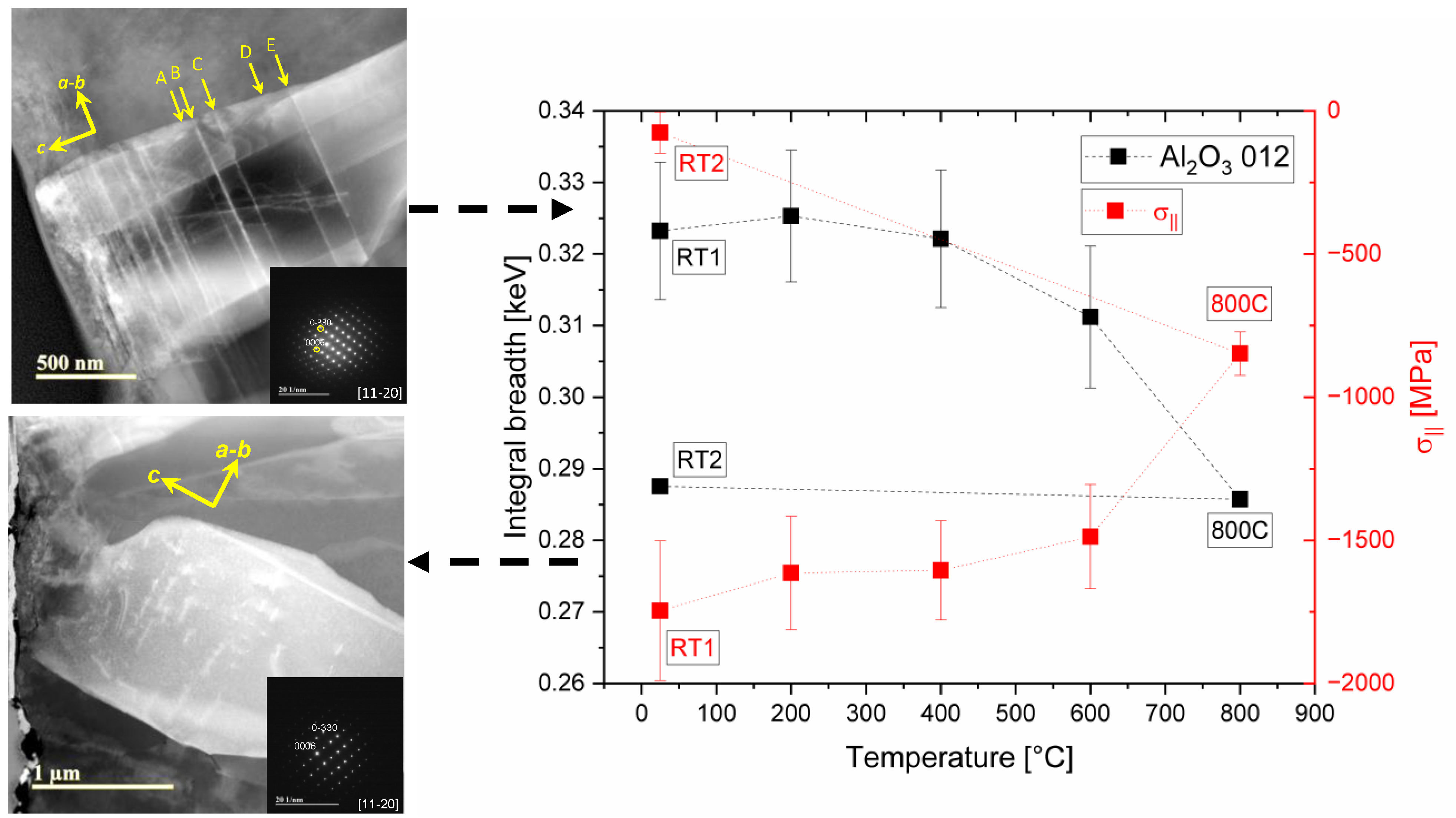
- Upon thermal cycling, the measured stress relaxation in α-Al2O3 is due to annihilation of defects, as observed by the reduction in integral breadth for the 012 diffraction line as well as the contrast change in the dark-field STEM analysis.
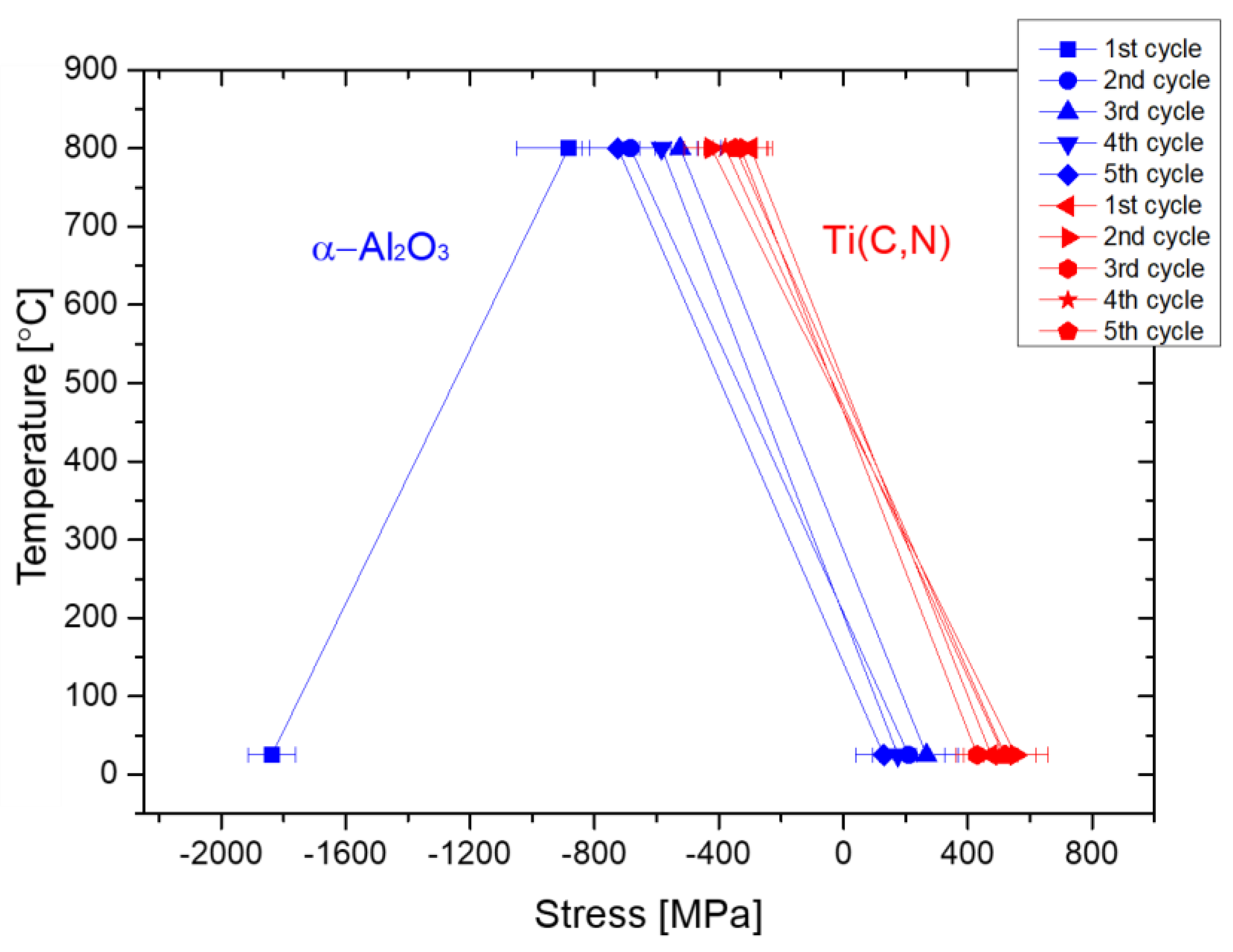
- By increasing the number of cycles, a reversible temperature-dependent stress condition in the α-Al2O3 layer is achieved.
- Top-blasting does not affect the initial microstructure and residual stress of the Ti(C,N) layer.
- The Ti(C,N) layer shows a temperature-dependent reversible cycling behavior and an elastic deformation behavior in the temperature range investigated.
- Observed deviations between theoretical stresses and measured stresses can be associated with microcrack formation during the cooling step in the CVD process.
- The zero stress condition for the temperature-dependent reversible stress behavior of the Ti(C,N)/α-Al2O3 system sets at a temperature between 300 and 500 °C, which is a favorable condition that can contribute to the formation and propagation of thermomechanical cracks in, e.g., milling inserts.
- The results show that the matching of CTE between the substrate and coating is crucial to reduce cycling stresses that promotes crack propagation. Technically, this could be achieved by cemented carbide substrates with higher CTE (by, for example, increasing the binder content) or by layers with low CTE, such as Zr(C,N) or Hf(C,N). This, alongside tailored top-blasting parameters, is crucial for delaying crack opening in interrupted machining operations.
Author Contributions
Funding
Institutional Review Board Statement
Informed Consent Statement
Data Availability Statement
Acknowledgments
Conflicts of Interest
References
- Sadik, I. An Introduction to Cutting Tools Materials and Applications; Elanders: Mölndal, Sweden, 2013; ISBN 978-91-637-4920-9. [Google Scholar]
- García, J.; Collado Cipres, V.; Blomqvist, A.; Kaplan, B. Cemented carbide microstructures: A review. Int. J. Ref. Met. Hard Mater. 2019, 80, 40–68. [Google Scholar] [CrossRef]
- Mitterer, C. PVD and CVD Hard Coatings. Encyclopedia Comprehensive Hard Materials; Elsevier Ltd.: Amsterdam, The Netherlands, 2014; Volume 2, pp. 449–467. [Google Scholar]
- García, J.; Moreno, M.; Östby, J.; Persson, J.; Pinto, H. Design of coated cemented carbide with improved comb crack resistance. In Proceedings of the Plansee Seminar 2017, Reutte, Austria, 29 May–2 June 2017. [Google Scholar]
- Klaus, M.; Genzel, C.; Holzschuh, H. Residual stress depth profiling in complex hard coating systems by X-ray diffraction. Thin Solid Films 2008, 517, 1172–1176. [Google Scholar] [CrossRef]
- Schalk, N.; Mitterer Ch Czettl, C.; Sartory, B.; Penoy, M.; Michotte, C. Dry blasting of alpha and kappa-Al2O3 CVD hard coatings: Friction behavior and thermal stress relaxation. Tribol. Lett. 2013, 52, 147–154. [Google Scholar] [CrossRef]
- Teppernegg, T.; Klünsner, T.; Angerer, P.; Tritremmel, C.; Czettl, C.; Keckes, J.; Ebner, R.; Pippan, R. Evolution of residual stress and damage in coated hard metal milling inserts over the complete tool life. Int. J. Ref. Met. Hard Mater. 2014, 47, 80–85. [Google Scholar] [CrossRef]
- Bartosik, M.; Pitonak, R.; Keckes, J. In Situ High Temperature X-Ray Diffraction Reveals Residual Stress Depth Profiles in Blasted TiN Hard Coatings. Adv. Eng. Mat. 2011, 13, 705–711. [Google Scholar] [CrossRef]
- García, J.; Pinto, H.; Ramos-Moore, E.; Espinoza, C.; Östby, J.; Coelho, R. In-situ high temperature stress analysis of Ti(C,N) coatings on functionally graded cemented carbides by energy dispersive synchrotron X-ray diffraction. Int. J. Ref. Met. Hard Mater. 2016, 56, 27–34. [Google Scholar] [CrossRef]
- Faksa, L.; Daves, W.; Ecker, W.; Klünsner, T.; Tkadletz, M.; Czettl, C. Effect of shot peening on residual stresses and crack closure in CVD coated hard metal cutting inserts. Int. J. Ref. Met. Hard Mater. 2019, 82, 174–182. [Google Scholar] [CrossRef]
- Stylianou, R.; Velic, D.; Daves, W.; Ecker, W.; Stark, A.; Schell, N.; Tkadletz, M.; Schalk, N.; Czettl, C.; Mitterer, C. Stress relaxation through thermal crack formation in CVD TiCN coatings grown on WC-Co with different Co contents. Int. J. Ref. Met. Hard Mater. 2020, 86, 105012. [Google Scholar] [CrossRef]
- Stylianou, R.; Velic, D.; Daves, W.; Ecker, W.; Tkadletz, M.; Schalk, N.; Czettl, C.; Mitterer, C. Thermal crack formation in Ti(C,N)/Al2O3 bilayer coatings grown by thermal CVD WC-Co substrates with varied Co content. Surf Coat Techn. 2020, 392, 125687. [Google Scholar] [CrossRef]
- Genzel, C.; Denks, I.A.; Gibmeier, J.; Klaus, M.; Wagener, G. The materials science synchrotron beamline EDDI for energy-dispersive diffraction analysis, Nuclear Instruments and Methods. In Physics Research Section A: Accelerators, Spectrometers, Detectors and associated Equipment; Elsevier: Amsterdam, The Netherlands, 2007; Volume 578, pp. 23–33. [Google Scholar]
- Klaus, M.; Garcia-Moreno, F. The 7T-MPW-EDDI Beamline at Bessy II. J. Large Scale Res. Facil. 2016, 2, A40. [Google Scholar] [CrossRef] [Green Version]
- Klaus, M.; Genzel, C.; García, J. Nondestructive separation of residual stress and composition gradients in thin films by angle- and energy-dispersive X-ray diffraction. II. Experimental validation. J. Appl. Cryst. 2017, 50, 265–277. [Google Scholar] [CrossRef]
- Stefenelli, M.; Todt, J.; Riedl, A.; Ecker, W.; Müller, T.; Daniel, R.; Burghammer, M.; Keckes, J. X-ray analysis of residual stress gradients in TiN coatings by Laplace space approach and cross sectional nanodiffraction: A critical comparison. J. Appl. Cryst. 2013, 46, 1378–1385. [Google Scholar] [CrossRef] [Green Version]
- Noyan, I.C.; Huang, T.C.; York, B.R. Residual stress/strain analysis in thin films by X-ray diffraction. Crit. Rev. Solid State Mater. Sci. 1995, 20, 125–177. [Google Scholar] [CrossRef]
- Noyan, I.C.; Cohen, J.B. Residual Stress: Measurement by Diffraction and Interpretation; Springer: Berlin/Heidelberg, Germany, 1987. [Google Scholar]
- Macherauch, E.; Müller, P. Das sin²ψ—Verfahren der röntgenographischen Spannungsmessung. Z. Angew. Physik 1961, 13, 305–312. [Google Scholar]
- Eshelby, J.D. The Determination of the Elastic Field of an Ellipsoidal Inclusion, and Related Problems. Proc. Roy. Soc. 1957, A241, 376–396. [Google Scholar]
- Kröner, E. Berechnung der elastischen Konstanten des Vielkristalls aus den Konstanten des Einkristalls. Z. Physik 1958, 151, 504–518. [Google Scholar] [CrossRef]
- Gao, C.; Zhao, Z.; Li, Z. Modeling of thermal stresses in elastic multilayer coating systems. J. Appl. Phys. 2015, 117, 055305. [Google Scholar] [CrossRef]
- El Azhari, I.; García, J.; Soldera, F.; Suarez, S.; Jiménez-Piqué, E.; Mücklich, F.; Llanes, L. Contact damage investigation of CVD carbonitride hard coatings deposited on cemented carbides. Int. J. Ref. Met. Hard Mater. 2020, 86, 105050. [Google Scholar] [CrossRef]
- Ruppi, S.; Larsson, A.; Flink, A. Nanoindentation hardness, texture and microstructure of α-Al2O3 and κ-Al2O3 coatings. Thin Solid Films 2008, 516, 5959–5966. [Google Scholar] [CrossRef]
- Friedrich, C.; Berg, G.; Broszeit, E.; Berger, C. Datensammlung zu Hartstoffeigenschaften. Mater. Werkst. 1997, 28, 59–76. [Google Scholar] [CrossRef]
- Wachtman, J.B.; Scuderi, T.G.; Cleek, G.W. Linear thermal expansion of aluminium oxide. J. Am. Ceram. Soc. 1961, 10, 319–323. [Google Scholar]
- Kral, C.; Lengauer, W.; Rafaja, D.; Ettmayer, P. Critical review on the elastic properties of transition metal carbides, nitrides and carbonitrides. J. Alloys Compd. 1998, 265, 215–233. [Google Scholar] [CrossRef]
- Aigner, K.; Lengauer, W.; Rafaja, D.; Ettmayer, P. Lattice parameters and thermal expansion of Ti(CxN1-x), Zr(CxN1-x), Hf(CxN1-x) and TiN1-x from 298 to 1473 K as investigated by high-temperature X-ray diffraction. J. Alloys Compd. 1994, 215, 121–126. [Google Scholar] [CrossRef]
- Halvarsson, M.; Langer, V.; Vuorinen, S. Determination of the thermal expansion of α-Al2O3 by high temperature XRD. Surf. Coat. Technnol. 1995, 76–77, 358–362. [Google Scholar] [CrossRef]
- De Keijser, T.H.; Langford, J.I.; Mittemeijer, E.J.; Vogels, A.B.P. Use of the Voigt function in a single-line method for the analysis of X-ray diffraction line broadening. J. Appl. Cryst. 1982, 15, 308–314. [Google Scholar] [CrossRef]
- Delhez, R.; De Keijser, T.H.; Mittemeijer, E.J. Determination of crystallite size and lattice distortions through X-ray diffraction line profile analysis. Fresenius Z. Anal. Chem. 1982, 312, 1–16. [Google Scholar] [CrossRef]
- Apel, D.; Klaus, M.; Genzel, C.; Balzar, D. Rietveld refinement of energy-dispersive synchrotron measurements. Z. Krist. 2011, 226, 934–943. [Google Scholar] [CrossRef]
- Rojas, D.; Garcia, J.; Prat, O.; Agudo, L.; Carrasco, C.; Kaysser-Pyzalla, A.R. Effect of processing parameters on the evolution of dislocation density and sub-grain size of a 12% Cr heat resistant steel during creep at 650° C. Mater. Sci. Eng. A 2011, 528, 1372–1381. [Google Scholar] [CrossRef]
- Gassner, M.; Schalk, N.; Tkadletz, M.; Czettl, C.; Mitterer, C. Thermal crack network on CVD TiCN/α-Al2O3 coated cemented carbide cutting tools. Int. J. Ref. Met. Hard Mater. 2019, 81, 1–6. [Google Scholar] [CrossRef]
- Barbatti, C.; García, J.; Pinto, H.; Kostka, A.; Di Prinzio, A.; Staia, M.; Pitonak, R.; Pyzalla, A. Influence of micro-blasting on the microstructure and residual stresses of CVD κ-Al2O3 coatings. Surf. Coat. Technol. 2009, 203, 3708–3717. [Google Scholar] [CrossRef] [Green Version]
- Ekström, E. Effect of texture and blasting pressure on residual stresses and surface modifications in wet sand blasted α-Al2O3 coating. Master’s Thesis, Linköping University, Linköping, Sweden, 2015. [Google Scholar]
- Ramos-Moore, E.; Espinoza, C.; Coelho, R.; Pinto, H.; Brito, P.; Soldera, F.; Mücklich, F.; García, J. Investigations on thermal stresses of a graded Ti (C, N) coating deposited on WC-Co hardmetal. Adv. Mater. Res. 2014, 996, 848–854. [Google Scholar] [CrossRef] [Green Version]
- Chien, H.; Diaz-Jimenez, C.; Rohrer, G.S.; Ban, Z.; Prichard, P.; Liu, Y. The influence of residual thermal stresses on the mechanical properties of multilayer -Al2O3 /TiCxN1-x coatings on WC/Co cutting tools. Surf. Coat. Technol. 2013, 215, 119–126. [Google Scholar] [CrossRef]
- Gruber, D.P.; Kiefer, D.; Rössler, R.; Beckmann, F.; Tkadletz, M.; Klünsner, T.; Czettl, C.; Keckes, J.; Gibmeier, J. 20 Hz synchrotron Z-ray diffraction analysis in laser-pulsed WC-Co hard metal reveals oscillatory stresses and reversible composite plastification. Int. J. Ref. Met. Hard Mater. 2019, 82, 121–128. [Google Scholar] [CrossRef]
- Ruppi, S. Cemented carbide body with high wear resistance and extra tough behavior. U.S. Patent 2000/6015614 A1, 18 January 2000. [Google Scholar]
- Ruppi, S. Enhanced performance of α-Al2O3 coatings by control of crystal orientation. Surf. Coat. Technol. 2008, 202, 4257–4269. [Google Scholar] [CrossRef]
- Tkadletz, M.; Keckes, J.; Schalk, N.; Krajinovic, I.; Burghammer, M.; Czettl, C.; Mitterer, C. Residual stress gradients in α-Al2O3 hard coatings determined by pencil-beam X-ray nano-diffraction: The influence of blasting media. Surf. Coat. Technol. 2015, 262, 134–140. [Google Scholar] [CrossRef]
- Hockey, B. Plastic deformation of aluminum oxide by indentation and abrasion. J. Am. Ceram. Soc. 1971, 54, 223–231. [Google Scholar] [CrossRef]
- Karlsson, L.; Hörling, A.; Johansson, M.P.; Hultman, L.; Ramanath, G. The influence of thermal annealing on residual stresses and mechanical properties of arc-evaporated TiCxN1-x (X = 0, 0.15 and 0.45) thin films. Acta Mater. 2002, 50, 5103–5114. [Google Scholar] [CrossRef]
- El Azhari, I.; Garcia, J.; Zamanzade, M.; Soldera, F.; Pauly, C.; Llanes, L.; Mücklich, F. Investigations on micro-mechanical properties of polycrystalline Ti(C,N) and Zr(C,N) coatings. Acta Mater. 2018, 149, 364–376. [Google Scholar] [CrossRef] [Green Version]
- Riley, F.L. Structural Ceramics: Fundamentals and Case Studies; Cambridge University Press: Cambridge, UK, 2009. [Google Scholar]
- Klaus, M.; Genzel, C. Multilayer Systems for Cutting Tools: On the Relationship between Coating Design, Surface Processing, and Residual Stress. Adv. Eng. Mater. 2011, 13, 845–850. [Google Scholar] [CrossRef]
- Genzel, C. X-Ray Stress Gradient Analysis in Thin Layers—Problems and Attempts at Their Solution. Phys. Stat. Sol. A 1997, 159, 283–296. [Google Scholar] [CrossRef]
- Klaus, M.; Denks, I.A.; Genzel, C. X-Ray Diffraction Analysis of Nonuniform Residual Stress Fields under Difficult Conditions. Mater. Sci. Forum 2006, 524–525, 601–606. [Google Scholar] [CrossRef]
- AB Sandvik Coromant. Measurement and Modeling of Temperature Fluctuations in Milling Operations; AB Sandvik Coromant: Sandviken, Sweden, 2019. [Google Scholar]


| Primary Beam | 0.5 × 0.5 mm² |
|---|---|
| Absorber | - |
| Secondary Optics | double slit system 0.03 × 8 mm² (equatorial x axial), Δ2θ < 0.01 |
| Diffraction Angle | 2θ = 9° |
| XSA-Mode | symmetrical ψ-Mode (reflection), ψ = 0° to 77°, |
| Detector | Low energy solid state Ge detector (Canberra Model GL0110) |
| Counting Time | 100 s |
| Calibration | gold powder (standard specimen on glass plate) |
| Energy Range | 10–80 keV |
| Component | Hkl | ||
|---|---|---|---|
| α-Al2O3 | 012/024 | –0.685 | 3.36 |
| Ti(C,N) | 200 | –0.425 | 2.665 |
| 220 | –0.465 | 2.795 |
| Substrate/Coating Layer | Young’s Modulus (GPa) | Poisson Coefficient, υ | Average CTE (20–800 °C) (10−6/K) | Film Thickness (μm) |
|---|---|---|---|---|
| WC-Co | 620 ± 20 [23] | 0.22 [23] | 5.7 [23] | - |
| α-Al2O3 | 440 ± 20 [24] | 0.22 [25] | a: 8.4/c: 9.0 [26] | 4.5 |
| Ti(C,N) | 450 ± 20 [27] | 0.19 [25] | 9.0 [28] | 4.5 |
Publisher’s Note: MDPI stays neutral with regard to jurisdictional claims in published maps and institutional affiliations. |
© 2021 by the authors. Licensee MDPI, Basel, Switzerland. This article is an open access article distributed under the terms and conditions of the Creative Commons Attribution (CC BY) license (http://creativecommons.org/licenses/by/4.0/).
Share and Cite
García, J.; Moreno, M.; Wan, W.; Apel, D.; Pinto, H.; Meixner, M.; Klaus, M.; Genzel, C. In Situ Investigations on Stress and Microstructure Evolution in Polycrystalline Ti(C,N)/α-Al2O3 CVD Coatings under Thermal Cycling Loads. Crystals 2021, 11, 158. https://0-doi-org.brum.beds.ac.uk/10.3390/cryst11020158
García J, Moreno M, Wan W, Apel D, Pinto H, Meixner M, Klaus M, Genzel C. In Situ Investigations on Stress and Microstructure Evolution in Polycrystalline Ti(C,N)/α-Al2O3 CVD Coatings under Thermal Cycling Loads. Crystals. 2021; 11(2):158. https://0-doi-org.brum.beds.ac.uk/10.3390/cryst11020158
Chicago/Turabian StyleGarcía, José, Maiara Moreno, Wei Wan, Daniel Apel, Haroldo Pinto, Matthias Meixner, Manuela Klaus, and Christoph Genzel. 2021. "In Situ Investigations on Stress and Microstructure Evolution in Polycrystalline Ti(C,N)/α-Al2O3 CVD Coatings under Thermal Cycling Loads" Crystals 11, no. 2: 158. https://0-doi-org.brum.beds.ac.uk/10.3390/cryst11020158