Enlarging the Eyebox of Maxwellian Displays with a Customized Liquid Crystal Dammann Grating


1
College of Optics and Photonics, University of Central Florida, Orlando, FL 32816, USA
2
Himax Display, Inc., Tainan City 74148, Taiwan
*
Author to whom correspondence should be addressed.
Crystals 2021, 11(2), 195; https://0-doi-org.brum.beds.ac.uk/10.3390/cryst11020195
Submission received: 1 February 2021
/
Revised: 14 February 2021
/
Accepted: 16 February 2021
/
Published: 17 February 2021
(This article belongs to the Special Issue Patterned-Liquid-Crystal for Novel Displays)
Abstract
:The Maxwellian view offers a promising approach to overcome the vergence-accommodation conflict in near-eye displays, however, its pinhole-like imaging naturally limits the eyebox size. Here, a liquid crystal polymer-based Dammann grating with evenly distributed energy among different diffraction orders is developed to enlarge the eyebox of Maxwellian view displays via pupil replication. In the experiment, a 3-by-3 Dammann grating is designed and fabricated, which exhibits good efficiency and high brightness uniformity. We further construct a proof-of-concept Maxwellian view display breadboard by inserting the Dammann grating into the optical system. The prototype successfully demonstrates the enlarged eyebox and full-color operation. Our work provides a promising route of eyebox expansion in Maxwellian view displays while maintaining full-color operation, simple system configuration, compactness, and lightweight.
1. Introduction
Augmented reality (AR), virtual reality (VR), and mixed reality (MR) near-eye displays are emerging rapidly [1] because of their potential to revolutionize entertainment, education, engineering, and healthcare. A major obstacle that influences the user experience of these AR/VR displays is the vergence-accommodation conflict (VAC) [2,3]. For most existing near-eye displays, the depth cue is generated by binocular disparity, where two different images are respectively delivered to the observer’s left and right eyes. On the other hand, the virtual image plane is fixed so that the accommodation distance is not image-dependent. Such a mismatch between vergence and accommodation cues results in visual discomfort and fatigue.
To tackle VAC, plethora of methods have been proposed, including but not limited to multi-focal plane displays [4,5,6], varifocal plane displays [7,8], integral imaging-based displays [9,10], holographic displays [11,12,13], and Maxwellian view displays [14,15,16,17,18]. Among them, Maxwellian view is a special display to bypass this VAC issue by providing a very large depth of focus. Moreover, the optical system of a Maxwellian view display is usually quite energy efficient, simple, and compact. However, due to its pinhole-like imaging, the eyebox is limited. Upon eye movement, the viewpoint can be easily missed out by the pupil.
In this paper, we propose and demonstrate a Maxwellian view near-eye display with an enlarged eyebox achieved by viewpoint replication. To create multiple viewpoints at the same time, we propose to insert a Dammann grating with multiple diffraction orders, good overall efficiency, and high brightness uniformity into the optical system. In the experiment, we design and fabricate a customized Dammann grating based on patterned liquid crystal (LC) polymers. A simple proof-of-concept prototype is also established. The use of a Dammann grating in a Maxwellian view near-eye display can offer full-color imaging and enlarged eyebox, while keeping a compact size and lightweight.
2. Maxwellian View Near-Eye Displays
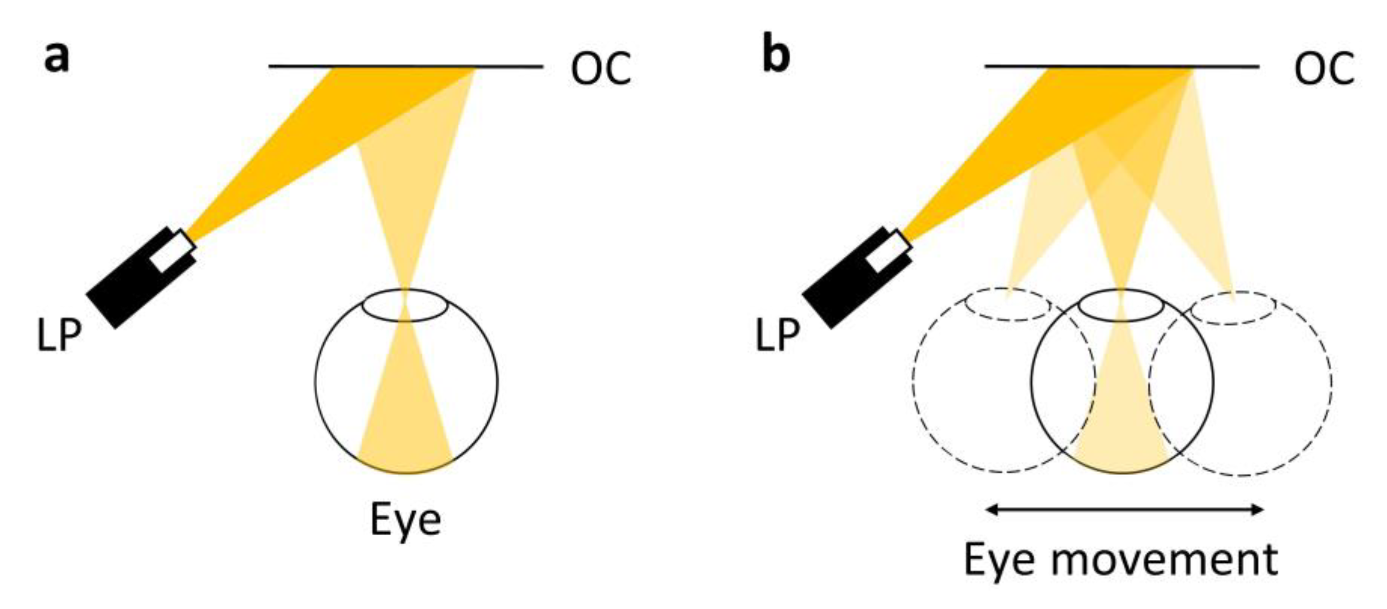
Figure 1a depicts a typical configuration of Maxwellian view near-eye display. The image produced by the laser beam scanning projector (LP) is incident on an optical combiner (OC) with focusing power. The eye views the image by placing the pupil near the focal point of the OC. The image is directly formed on the retina and is always in focus, regardless of the optical power of the eye lens. Ascribed to this pinhole-like imaging, this focal point of OC can be easily missed upon eye movement. To ensure that the image can be observed by the eye (as shown in Figure 1b), two common approaches have been investigated, namely pupil steering and pupil replication.
Pupil steering is generally more energy efficient, as it creates one viewpoint at a time. This can be realized by adjusting the eyebox in spatial frequency domain or using a mechanically movable device [14]. However, these methods usually result in a much more complex, high cost or large volume display system. By contrast, generating multiple viewing points in space at the same time can be much easier, but some of the optical power will be inevitably lost. Previously, 1D and 2D pupil replication in Maxwellian view near-eye displays with simple optical systems have been reported [15,16]. Nonetheless, they either suffer from single color operation, image artifacts, or limited eyebox expansion.
3. Improved LC Dammann Gratings
For viewpoint replication in Maxwellian view near-eye displays, multiple viewpoints with uniform brightness distribution are desired. Generating multiple views in space can be realized by diffracting beams into multiple orders in the angular domain. Although using an arbitrary grating may create a lot of viewpoints, it can hardly fulfil the requirement of evenly distributed optical power in those diffraction orders. Fortunately, Dammann gratings with optimizable diffraction orders can meet this challenge. They are binary gratings with calculated transition points within a period [19].
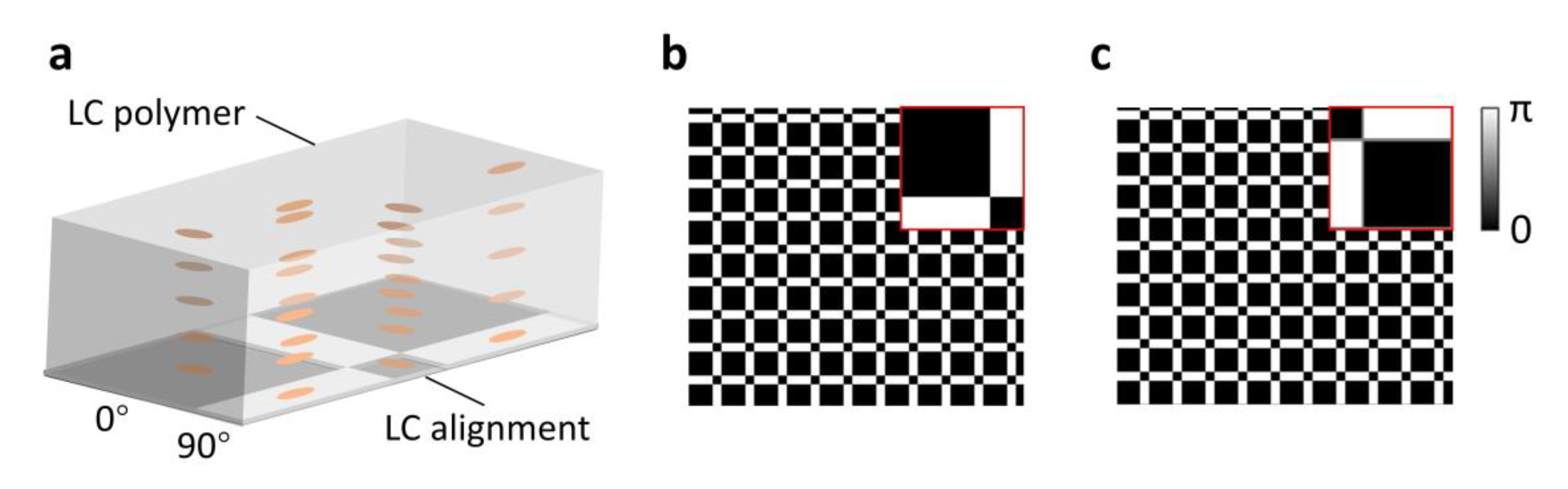
Here, patterned LC polymers are employed to fabricate the Dammann grating. As shown in Figure 2a, the LC polymer consists of a photoreactive mesogen and an alignment layer. To create the patterned binary phase, the LCs are aligned in either 0° or 90° with the desired alignment pattern created from a spatial light modulator (SLM), and the LC polymer film serves as a patterned half-wave plate. For incident left-handed circularly polarized light, its polarization is flipped to right-handed upon transmitting through such a wave plate and a geometric phase term is added [20]. Most previous Dammann grating designs have focused on achieving perfect binary gratings. However, in an LC-based Dammann grating, line defects can appear at the LC alignment domain boundaries [21]. As we will compare later, if LC alignment at the domain boundary has an abrupt change, the overall alignment quality would deteriorate, causing unwanted misalignment and light scattering. Therefore, in our design, we take this boundary continuity into account by inserting a single alignment transition pixel line with a 45° alignment angle in between two domains. With predefined rotation direction in between two domains, the unwanted misalignment can be mostly eliminated. During the optical optimization of the Dammann grating, the diffraction effect from the transition buffer pixels is also considered. Meanwhile, since we are using an SLM for patterning, the effect of discrete pixels needs to be accounted for as well.
To prove the concept, a 3-by-3 Dammann grating is optimized with good efficiency and high uniformity. The optimization is performed by sweeping the transition points of a 2D binary grating and the efficiency of each diffraction order is numerically calculated by the Huygens-Fresnel principle with the Fraunhofer approximation. As a comparison, we also adopt a design from perfect binary gratings [19]. The transition points for the control design and our design are 0.7353 and 0.2766, respectively, as depicted in Figure 2b,c. It is important to note that for LC polarization gratings with continuous LC director rotation, the diffraction pattern is strongly circular polarization-dependent [16]. For our customized Dammann gratings, the grating is almost binary and symmetric in 2D space, and thus the far-field diffraction pattern will be nearly the same for both circular polarizations. Consequently, the Dammann grating is suitable for both unpolarized and polarized light operations.
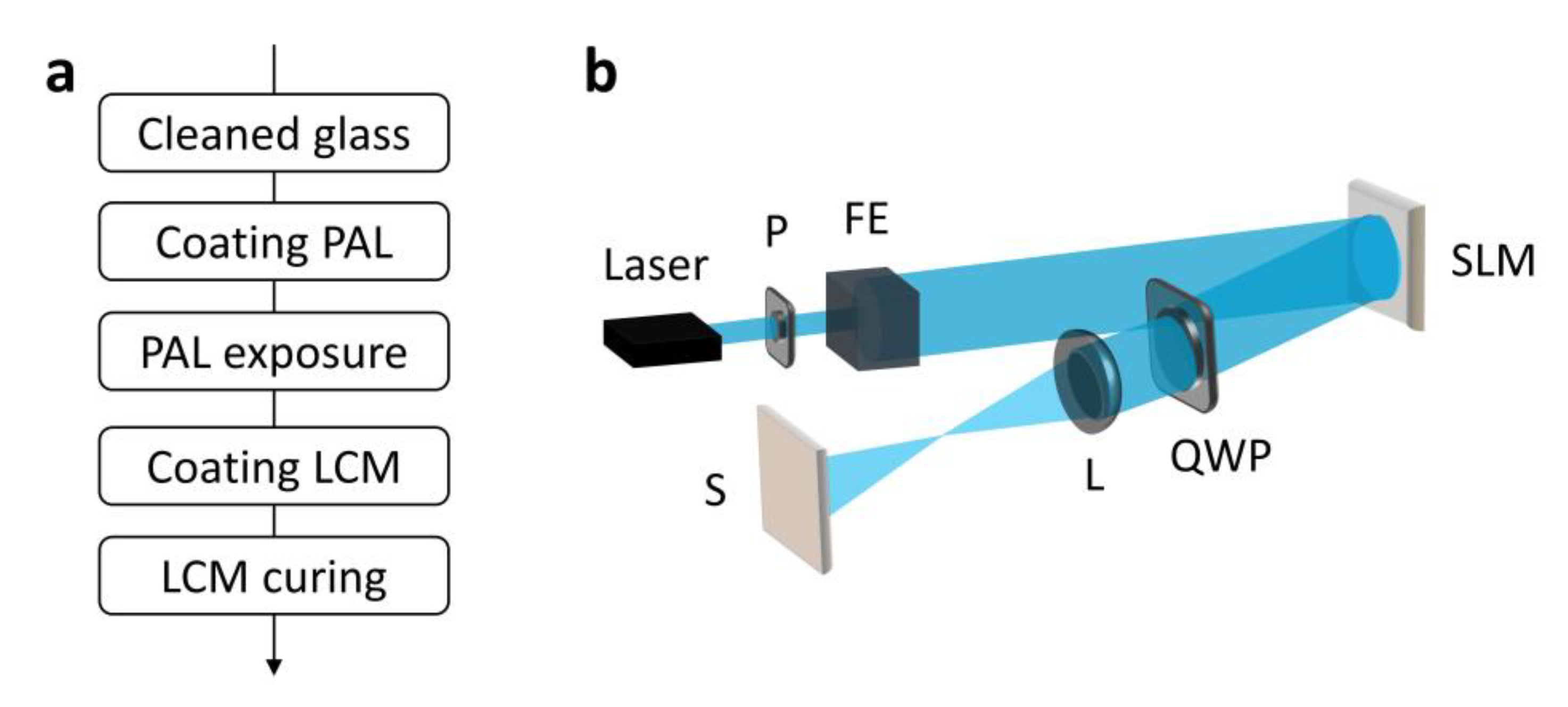
In experiment, both reference and customized Dammann gratings are fabricated, following the procedure shown in Figure 3a. First, a thin film of photoalignment material, 0.4wt% Brilliant Yellow (BY, from Tokyo Chemistry Industry) dissolved in dimethylformamide (DMF) solvent, is spin-coated onto cleaned glass substrates with 500 rpm for 5 s and 3000 rpm for 30 s. Then, the substrates coated with BY are mounted on the sample holder for exposure. The photoalignment material is responsive to linearly polarized short-wavelength light (e.g., UV, blue). Upon illumination, the photoalignment materials will be aligned perpendicular to the linear polarization of light, resulting in a minimum free-energy state [22,23]. The exposure setup is shown in Figure 3b, which is similar to that reported in [24], is to create the desired linear polarization field that matches the design. The employed SLM is a phase-only liquid-crystal-on-silicon (LCoS) device (Himax HX7322), the lens used in the setup has a focal length of ~8 cm, and the recording wavelength is 488 nm. In this setup, the incident light is linearly polarized along 45°, assuming that the LC alignment direction in SLM is along 0°. The fast axis of the quarter-wave plate is also placed along 45°. In this way, by increasing the phase retardation of SLM from 0 to 2π, the output linear polarization direction will be continuously rotated by π, and thus a full linear polarization control is achieved. The linear polarization patterning can be understood by the Jones matrix calculation [24]. After exposure, a reactive mesogen solution, consisting of 97wt% reactive mesogen RM257 (from LC Matter) and 3wt% photo initiator Irgacure 651 (from BASF) dissolved in toluene with a weight ratio of 1:3, is spin-coated onto the substrates with 2000 rpm for 30 s. As the final step, the samples are cured by a UV light (365 nm) for 5 min with ∼10 mW/cm2 irradiance.
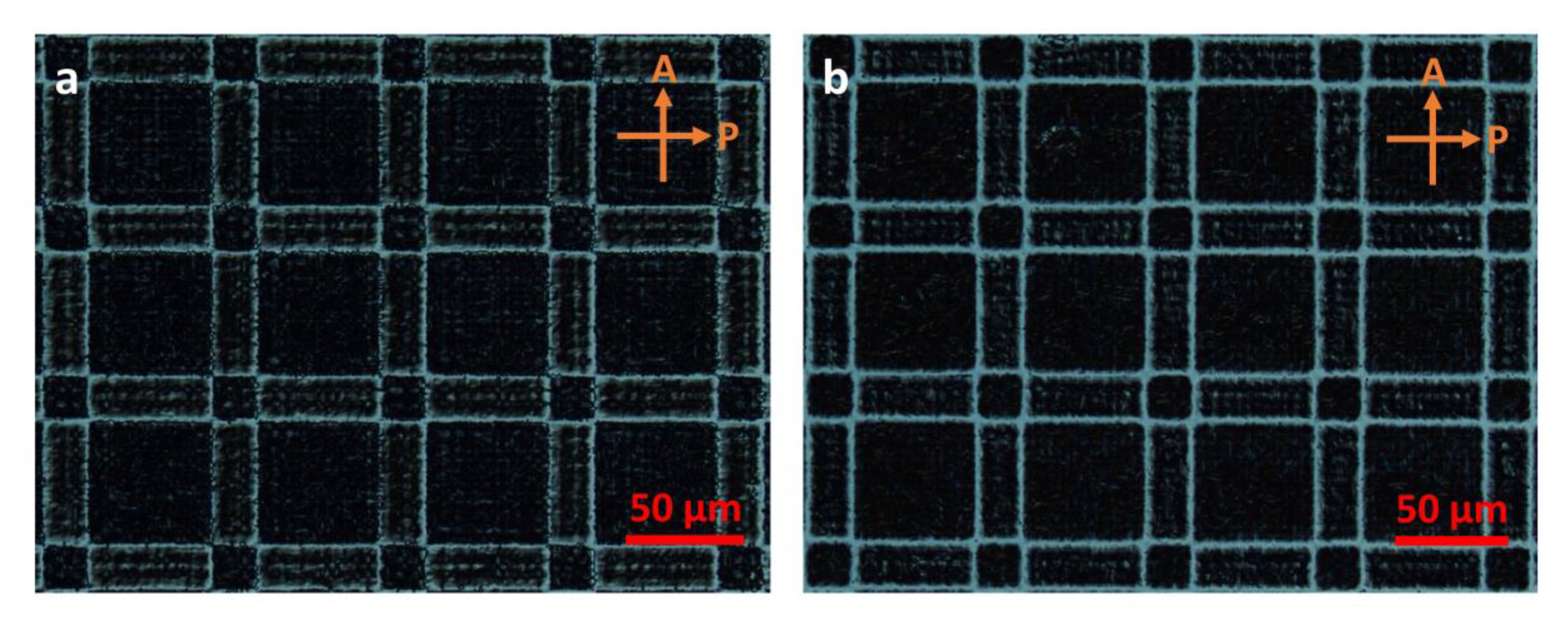
To characterize the fabricated LC Dammann gratings, polarized optical microscope (POM) images of reference grating and designed grating are recorded, as Figure 4 shows. Here, the alignment direction within a domain is parallel to the polarizer’s optic axis. In that sense, both 0° and 90° aligned LC domains will be dark under POM. However, at the boundary of different alignment directions, light leakage will be observed due to line defects (Figure 4a) or alignment transition (Figure 4b). As can be seen, the light leakage lines outline the alignment pattern, which agrees well with the designed phase pattern shown in Figure 2. For the reference grating, the light leakage lines are narrower. However, unwanted misalignment and defects are quite visible. Interestingly, with a predefined alignment transition, the alignment quality is much improved. The grating period of the customized grating is roughly 75 μm, which corresponds to ~0.41° first-order diffraction angle in the air for a green wavelength.
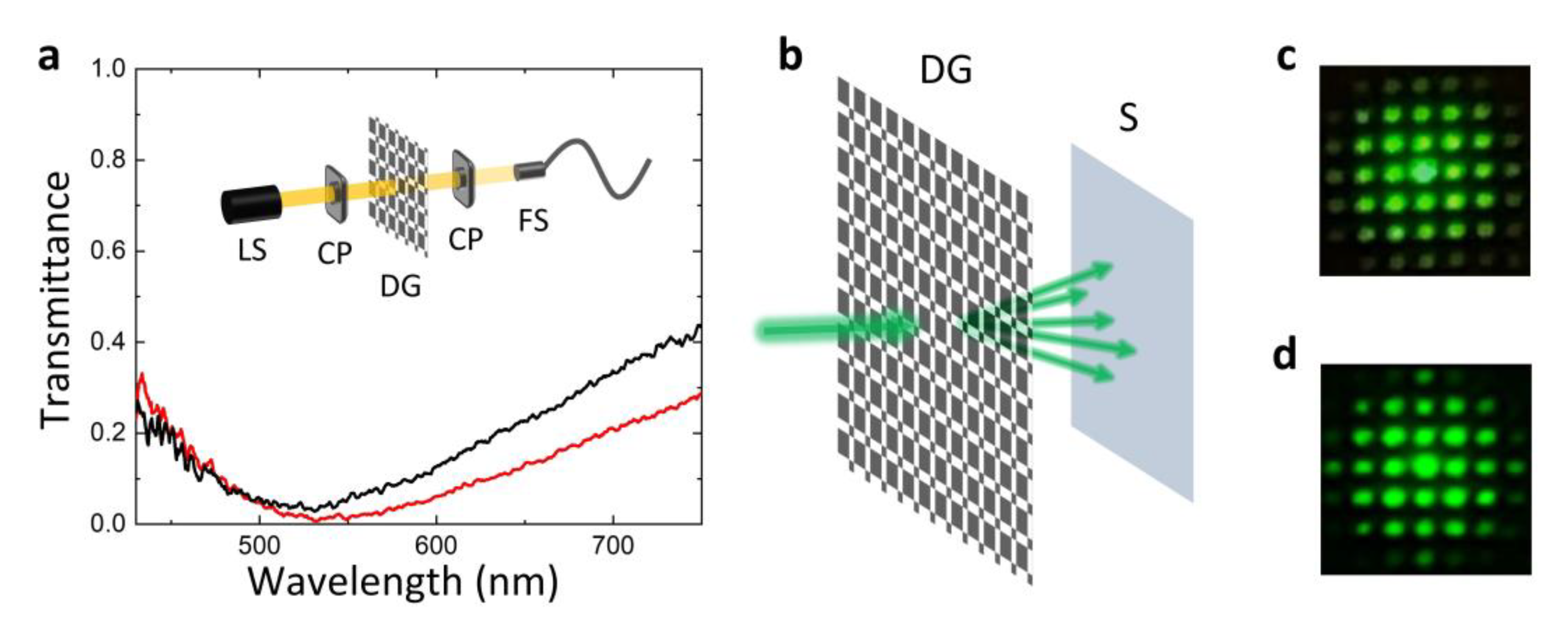
The half-wave wavelength of both fabricated Dammann gratings is characterized by inserting them in between two circular polarizers with the same handedness. As demonstrated in Figure 5a, the central wavelength appears at λ ≈ 530 nm. Noticeably, the customized Dammann grating can reach a reasonably good dark state, while the reference grating shows ~5% light leakage at λ ≈ 530 nm. This light leakage is mainly ascribed to the misalignment and defects, which cause light scattering. For the customized grating, its overall diffraction efficiency should follow the law upon wavelength changes, where Γ is the phase retardation of the LC polymer [20]. In fact, to overcome this wavelength-dependent diffraction efficiency, a multi-twist structure along thickness direction can be introduced, as reported in [25,26]. To observe the diffraction pattern of fabricated Dammann gratings, we put the samples in front of a green point source and use a camera to capture the transmitted light, as shown in Figure 5b. The diffraction patterns of reference grating and designed grating are manifested in Figure 5c,d, respectively. For both gratings, multiple diffraction orders are observed. Nevertheless, for the reference grating, the central 0th order shows much higher efficiency than other orders. Moreover, the higher orders of the reference grating exhibit a greater efficiency than those of the customized grating, and the diffraction pattern of the reference grating is more blurred, which is due mainly to LC misalignment and defects. For a well-aligned LC Dammann grating, the designed diffraction orders have more evenly distributed energy. Per our measurements, the diffraction efficiency of the customized Dammann gratings for green light and central 3-by-3 diffraction orders is ~45%, which is close to the simulation results (~55%). Here, the diffraction efficiency is defined as the power sum of the central 3-by-3 orders (in total 9 orders) divided by the total transmitted power. The uniformity, defined as (Imax − Imin)/(Imax + Imin), where Imax is the maximum intensity and Imin is minimum intensity, is measured as ~0.13, which agrees well with the simulation (~0.08).
4. Maxwellian View Displays With an Enlarged Eyebox
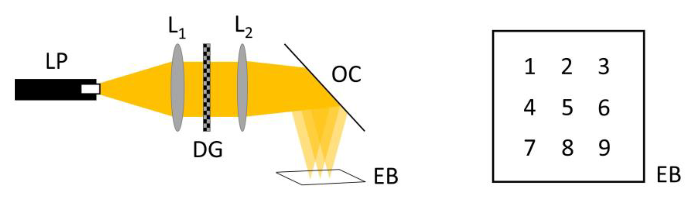
To show that Dammann grating can enlarge the eyebox of a Maxwellian view near-eye display, a proof-of-concept breadboard demo is constructed, as schematically shown in Figure 6. A laser beam scanning projector (Sony MP-CL1) is firstly collimated by a lens (L1). After passing through the fabricated Dammann grating (DG), an eyepiece lens (L2) is used to form the viewpoints. Since our Dammann grating is a 2D grating with multiple diffraction orders, the eyebox is enlarged in 2D space by several times. Here we mainly focus on the central 3-by-3 views, as numbered in Figure 6.
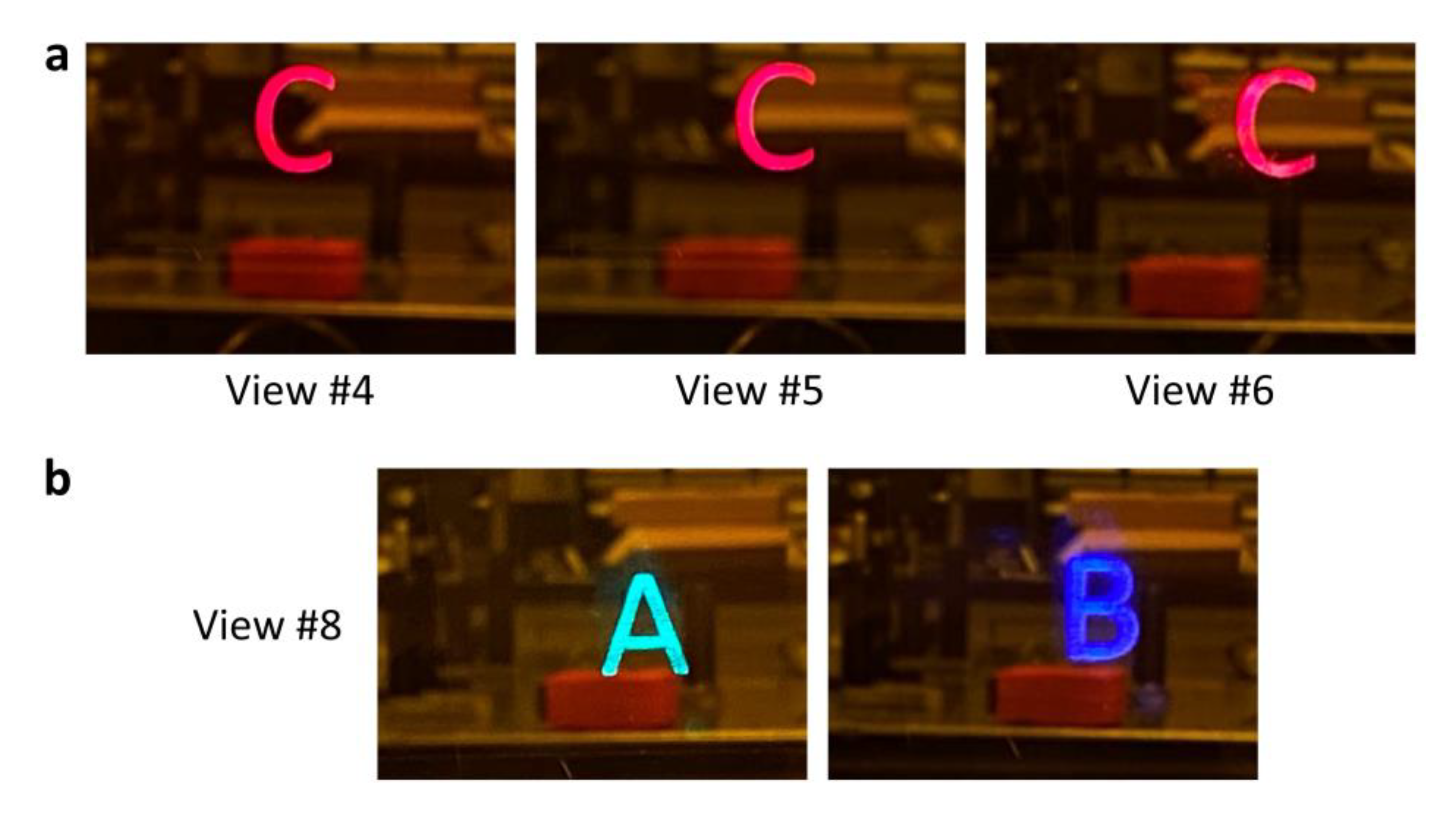
In our experiment, the optical combiner is a 2-inch non-polarizing beam splitter, and a camera is placed at the focal plane of the eyepiece lens to record the projected images. As demonstrated in Figure 7a, when the camera is shifted in the horizontal direction, different views of a red letter, C, is captured. To show that the Dammann grating is broadband, we also recorded the images of a green letter, A, and a blue letter, B, at view #8, which corresponds to the first diffraction order in the vertical direction.
In our feasibility demonstration, the distance between different viewpoints is ~1.4 mm along both x and y directions in the 2D space. From the geometry of the optical system, the viewpoint separation is closely related to the grating pitch (thus diffraction angle) and focal length of the eyepiece. Since here the grating pitch is quite large (~75 μm), the eyepiece needs to have a long focal distance (20 cm) to ensure a reasonable separation distance. In our demo, the field of view (FOV) is defined by the illumination system. However, if we have an illumination system that provides a large enough illumination area covering the entire eyepiece, the FOV of the Maxwellian view near-eye display will ultimately depend on the f/# of the eyepiece. In our optical setup, the eyepiece has an f/3.9, which corresponds to a maximum horizontal FOV of ~14.5° in theory. To enlarge the maximum FOV, a smaller f/# eyepiece is required, and thus a smaller grating pitch is needed. To fabricate a smaller pitch Dammann grating, decreasing the magnification factor of the exposure setup (Figure 3b) is an option. However, the total effective area of the grating will also be shrunk. Other options include using a predesigned photomask instead of an SLM or applying a different material other than LC polymer. With an improved fabrication technique, a Dammann grating with more uniform higher orders (e.g., 3-by-5) will be an intriguing choice for further enlarging the eyebox.
5. Conclusions
We proposed and demonstrated a Maxwellian view near-eye display with an enlarged eyebox for AR/VR/MR displays. The eyebox expansion is achieved by pupil replication, which is physically realized by inserting a Dammann grating into the optical system. In the experiment, a customized 3-by-3 Dammann grating was fabricated using patterned LC polymers which achieved good efficiency and high brightness uniformity. Through constructing a Maxwellian view display breadboard, an enlarged eyebox and full color operation are proven. To further enlarge FOV, a smaller pitch Dammann grating is desired. Our work shows a very promising means of eyebox expansion in Maxwellian view display while maintaining full-color operation, simple system configuration, compactness, and lightweight.
Author Contributions
Methodology, Z.H., K.Y., and K.-H.F.-C.; writing—original draft preparation, Z.H.; writing—review and editing, Z.H. and S.-T.W.; supervision, S.-T.W. All authors have read and agreed to the published version of the manuscript.
Funding
Air Force Office of Scientific Research (FA9550-14-1-0279).
Institutional Review Board Statement
Not applicable.
Informed Consent Statement
Not applicable.
Data Availability Statement
Data is contained within the article.
Conflicts of Interest
The authors declare no conflict of interest.
References
- Zhan, T.; Yin, K.; Xiong, J.; He, Z.; Wu, S.T. Augmented reality and virtual reality: Perspectives and challenges. iScience 2020, 23, 101397. [Google Scholar] [CrossRef]
- Kramida, G. Resolving the vergence-accommodation conflict in head-mounted displays. IEEE Trans. Vis. Comput. Graph. 2016, 22, 1912–1931. [Google Scholar] [CrossRef] [PubMed]
- Hua, H. Enabling focus cues in head-mounted displays. Proc. IEEE 2017, 105, 805–824. [Google Scholar] [CrossRef]
- Zhan, T.; Xiong, J.; Zou, J.; Wu, S.T. Multifocal displays: Review and prospect. PhotoniX 2020, 1, 10. [Google Scholar] [CrossRef] [Green Version]
- Hu, X.; Hua, H. High-resolution optical see-through multi-focal-plane head-mounted display using freeform optics. Opt. Express 2014, 22, 13896–13903. [Google Scholar] [CrossRef]
- He, Z.; Yin, K.; Wu, S.T. Passive polymer-dispersed liquid crystal enabled multi-focal plane displays. Opt. Express 2020, 28, 15294–15299. [Google Scholar] [CrossRef]
- Dunn, D.; Tippets, C.; Torell, K.; Kellnhofer, P.; Akşit, K.; Didyk, P.; Myszkowski, K.; Luebke, D.; Fuchs, H. Wide field of view varifocal near-eye display using see-through deformable membrane mirrors. IEEE Trans. Visual. Comput. Graphics 2017, 23, 1322–1331. [Google Scholar] [CrossRef]
- Lee, S.; Jo, J.; Yoo, D.; Cho, J.; Lee, D.; Lee, B. Tomographic near-eye displays. Nat. Commun. 2019, 10, 2497. [Google Scholar] [CrossRef] [Green Version]
- Lanman, D.; Luebke, D. Near-eye light field displays. ACM Trans. Graph. 2013, 32, 220. [Google Scholar] [CrossRef]
- Huang, F.C.; Chen, K.; Wetzstein, G. The light field stereoscope: Immersive computer graphics via factored near-eye light field displays with focus cues. ACM Trans. Graph. 2015, 34, 60. [Google Scholar] [CrossRef]
- Wakunami, K.; Hsieh, P.Y.; Oi, R.; Senoh, T.; Sasaki, H.; Ichihashi, Y.; Okui, M.; Huang, Y.P.; Yamamoto, K. Projection-type see-through holographic three-dimensional display. Nat. Commun. 2016, 7, 12954. [Google Scholar] [CrossRef] [Green Version]
- Li, G.; Lee, D.; Jeong, Y.; Cho, J.; Lee, B. Holographic display for see-through augmented reality using mirror-lens holographic optical element. Opt. Lett. 2016, 41, 2486–2489. [Google Scholar] [CrossRef]
- Xiong, J.; Yin, K.; Li, K.; Wu, S.T. Holographic optical elements for augmented reality: Principles, present status, and future perspectives. Adv. Photonics Res. 2020, 1, 2000049. [Google Scholar]
- Park, J.H.; Kim, S.B. Optical see-through holographic near-eye-display with eyebox steering and depth of field control. Opt. Express 2018, 26, 27076–27088. [Google Scholar] [CrossRef]
- Kim, S.B.; Park, J.H. Optical see-through Maxwellian near-to-eye display with an enlarged eyebox. Opt. Lett. 2018, 43, 767–770. [Google Scholar] [CrossRef] [PubMed]
- Lin, T.; Zhan, T.; Zou, J.; Fan, F.; Wu, S.T. Maxwellian near-eye display with an expanded eyebox. Opt. Express 2020, 28, 38616–38625. [Google Scholar] [CrossRef] [PubMed]
- Yoo, C.; Chae, M.; Moon, S.; Lee, B. Retinal projection type lightguide-based near-eye display with switchable viewpoints. Opt. Express 2020, 28, 3116–3135. [Google Scholar] [CrossRef]
- Chang, C.; Cui, W.; Park, J.; Gao, L. Computational holographic Maxwellian near-eye display with an expanded eyebox. Sci. Rep. 2019, 9, 18749. [Google Scholar] [CrossRef]
- Zhou, C.; Liu, L. Numerical study of Dammann array illuminators. Appl. Opt. 1995, 34, 5961–5969. [Google Scholar] [CrossRef]
- Chen, P.; Wei, B.; Hu, W.; Lu, Y.Q. Liquid-Crystal-Mediated Geometric Phase: From Transmissive to Broadband Reflective Planar Optics. Adv. Mater. 2019, 32, 1903665. [Google Scholar] [CrossRef]
- Fan, F.; Yao, L.; Wang, X.; Shi, L.; Srivastava, A.K.; Chigrinov, V.G.; Kwok, H.S.; Wen, S. Ferroelectric liquid crystal Dammann grating by patterned photoalignment. Crystals 2017, 7, 79. [Google Scholar] [CrossRef] [Green Version]
- Schadt, M.; Schmitt, K.; Kozinkov, V.; Chigrinov, V. Surface-induced parallel alignment of liquid crystals by linearly polymerized photopolymers. Jpn. J. Appl. Phys. 1992, 31, 2155–2164. [Google Scholar] [CrossRef]
- Yin, K.; Xiong, J.; He, Z.; Wu, S.T. Patterning Liquid Crystal Alignment for Ultra-Thin Flat Optics. ACS Omega 2020, 5, 31485–31489. [Google Scholar] [CrossRef] [PubMed]
- Li, Y.; Liu, Y.; Li, S.; Zhou, P.; Zhan, T.; Chen, Q.; Su, Y.; Wu, S.T. Single-exposure fabrication of tunable Pancharatnam-Berry devices using a dye- doped liquid crystal. Opt. Express 2019, 27, 9054–9060. [Google Scholar] [CrossRef] [PubMed] [Green Version]
- Oh, C.; Escuti, M.J. Achromatic diffraction from polarization gratings with high efficiency. Opt. Lett. 2008, 33, 2287–2289. [Google Scholar] [CrossRef]
- Zou, J.; Zhan, T.; Xiong, J.; Wu, S.T. Broadband wide-view Pancharatnam–Berry phase deflector. Opt. Express 2020, 28, 4921–4927. [Google Scholar] [CrossRef]
Figure 1.
Schematic illustrations of (a) a typical Maxwellian view display and (b) a Maxwellian view display with enlarged eyebox. LP: laser projector; OC: optical combiner.
Figure 1.
Schematic illustrations of (a) a typical Maxwellian view display and (b) a Maxwellian view display with enlarged eyebox. LP: laser projector; OC: optical combiner.

Figure 2.
(a) Liquid crystal director distribution in a Dammann grating-patterned liquid crystal polymer film. (b) Phase profile of a control Dammann grating. (c) Phase profile of the customized Dammann grating. The insets show the phase profile within a repeating unit. Note that in (c), there is a single pixel line with π/2 phase between 0 and π phase domains.

Figure 3.
(a) LC Dammann grating fabrication workflow. (b) Exposure setup for recording the Dammann grating pattern on LC alignment layer. PAL: photo-alignment layer; LCM: liquid crystal mesogen; P: polarizer; FE: filtering and expansion; SLM: spatial light modulator; QWP: quarter-wave plate; L: lens; S: sample.

Figure 4.
Polarized optical microscope image of the fabricated LC Dammann grating: (a) reference grating (period ~72 μm), (b) designed grating (period ~75 μm). A: analyzer; P: polarizer.
Figure 4.
Polarized optical microscope image of the fabricated LC Dammann grating: (a) reference grating (period ~72 μm), (b) designed grating (period ~75 μm). A: analyzer; P: polarizer.

Figure 5.
(a) Measured (normalized) transmission spectra of the fabricated reference (black line) and customized (red line) Dammann gratings between two parallel circular polarizers. (b) Schematic of diffraction pattern characterization of the fabricated LC Dammann gratings. (c) Recorded diffraction pattern for the reference grating. (d) Recorded diffraction pattern for the customized grating where the phase profile has been optimized. LS: light source; CP: circular polarizer; DG: Dammann grating; FS: fiber spectrometer; S: screen.

Figure 6.
Schematic plot of the established Maxwellian view display with an enlarged eyebox. The eyebox is enlarged in 2D space, and the different viewpoints are numbered with the central view (0th diffraction order) numbered as #5. LP: laser projector; L1: collimation lens; DG: Dammann grating; L2: eyepiece; OC: optical combiner; EB: eyebox.

Figure 7.
(a) Captured images of a red letter, C, at different viewing positions. (b) Captured images of a green letter, A, and a blue letter, B, at viewpoint #8.
Figure 7.
(a) Captured images of a red letter, C, at different viewing positions. (b) Captured images of a green letter, A, and a blue letter, B, at viewpoint #8.

Publisher’s Note: MDPI stays neutral with regard to jurisdictional claims in published maps and institutional affiliations. |
© 2021 by the authors. Licensee MDPI, Basel, Switzerland. This article is an open access article distributed under the terms and conditions of the Creative Commons Attribution (CC BY) license (http://creativecommons.org/licenses/by/4.0/).
Share and Cite
MDPI and ACS Style
He, Z.; Yin, K.; Fan-Chiang, K.-H.; Wu, S.-T. Enlarging the Eyebox of Maxwellian Displays with a Customized Liquid Crystal Dammann Grating. Crystals 2021, 11, 195. https://0-doi-org.brum.beds.ac.uk/10.3390/cryst11020195
AMA Style
He Z, Yin K, Fan-Chiang K-H, Wu S-T. Enlarging the Eyebox of Maxwellian Displays with a Customized Liquid Crystal Dammann Grating. Crystals. 2021; 11(2):195. https://0-doi-org.brum.beds.ac.uk/10.3390/cryst11020195
Chicago/Turabian StyleHe, Ziqian, Kun Yin, Kuan-Hsu Fan-Chiang, and Shin-Tson Wu. 2021. "Enlarging the Eyebox of Maxwellian Displays with a Customized Liquid Crystal Dammann Grating" Crystals 11, no. 2: 195. https://0-doi-org.brum.beds.ac.uk/10.3390/cryst11020195
Note that from the first issue of 2016, this journal uses article numbers instead of page numbers. See further details here.