Article

Impact Performance of Steel Fiber-Reinforced Self-Compacting Concrete against Repeated Drop Weight Impact

1
Civil Engineering Department, Wasit University, Kut 52003, Iraq
2
School of Civil Engineering, SASTRA Deemed University, Thanjavur 613401, India
3
Polytechnic Institute, Far Eastern Federal University, 690922 Vladivostok, Russia
4
Higher School of Industrial, Civil and Road Construction, Peter the Great St. Petersburg Polytechnic University, 195251 St. Petersburg, Russia
5
Department of Machinery Parts and Theory of Mechanisms, Moscow Automobile and Road Construction University, 125319 Moscow, Russia
*
Author to whom correspondence should be addressed.
Submission received: 9 January 2021 / Revised: 17 January 2021 / Accepted: 19 January 2021 / Published: 22 January 2021

Abstract

:
The self-compacting concrete (SCC) was invented to overcome the compaction problems in deep sections, owing to its perfect workability characteristics. Steel fibers when used with SCC would affect the required fluidity characteristics but improve its impact resistance. In this research, an experimental work was conducted to evaluate the impact response of micro-steel fiber-reinforced SCC, under flexural impact. A 5.47 kg free-falling mass was dropped repeatedly from 100 mm height on the top center of 270 mm-length beam specimens. Eight mixtures with two design grades of 30 and 50 MPa were prepared to distinguish the normal and high-strength SCCs. The distinguishing variable for each design grade was the fiber content, where four volumetric contents of 0%, 0.5%, 0.75%, and 1.0% were used. The test results showed that the impact resistance and ductility were significantly improved due to the incorporation of micro-steel fibers. The percentage improvements were noticeably higher at failure stage than at cracking stage. For the 30 MPa mixtures, the maximum percentage improvements at cracking and failure stages were 543% and 836%, respectively. Weibull’s linear correlations with R2 values of 0.84 to 0.97 were obtained at the failure stage, which meant that the impact failure number followed the Wiebull distribution.

1. Introduction

Concrete is known for its weakness in tension. Several types of loading induce tensile stresses, among which is bending, which induces flexural tensile and compressive stresses. Therefore, it is essential in the design of flexural members, such as beams and slabs, to add sufficient quantity of reinforcing steel in the tension zone, to withstand the applied tensile flexural stresses. However, in some cases, the structural member might be subjected to undesirable stresses induced from unusual loading sources, for which the member was not deigned. Examples for the probable undesired loads are high temperature thermal loads due to accidental fire or impact forces. Examples of undesired accidental sudden impacts are hits from collision of moving vehicles and gravity falling objects from higher altitudes, or due to hits by military projectiles in the case of wars or terrorist attacks [1,2,3,4,5]. On the other hand, some other types of structures or constructional elements are already designed to withstand repeated impact forces. Examples of which are the hydraulic structures, offshore structures, and bridge piers, where the impact of water and water-borne materials is one of the main design loads [6,7,8], and runways of airplanes in airports [4,5,9]. Several testing methods were used to test the ability of concrete against impacts, while some of these tests were more representative to the target loading types, like projectile and blast tests [10,11,12,13,14]; these were quite difficult to perform in academic laboratories. The drop-weight test is the more usual test used to examine the performance of concrete material and structural performance against impact loads, while the one recommended by ACI 544-2R [14] is considered to be the simplest impact test. In this test, no load, displacement, strain or vibration measurements are required. Instead, the drop weight is simply left to freely fall multiple times and the number of repeated blows required to crack and fail the concrete specimen are recorded [14,15,16].
In the ACI 544-2R [14] test, concrete disc specimens supported on a rigid steel plate are used to perform the repeated impact loading, where the impact is transferred through a steel ball located on the center of the top surface. This test was used by many previous studies to assess the response of various concrete types reinforced with steel fibers under falling impacts [17,18,19,20], or other types of synthetic or natural fibers [21,22,23,24,25]. On the other hand, some other studies used a similar procedure on beam specimens placed on two simple supports, to perform repeated three-point flexural impact loading [25,26,27,28,29].
Mohammadi et al. [30] carried out experimental impact tests on 100 × 100 × 500 mm beams on a span of 400 mm, using a drop weight of 5.54 kg and a free fall height of 457 mm. The objective of the tests was to evaluate the material and structural impact behavior of Steel Fiber-Reinforced Concrete (SFRC), incorporating various fiber volumetric contents of 1.0%, 1.5%, and 2.0%. The fibers have a length of 25 and 50 mm (aspect ratios of 40 and 20) and were used in different combinations of 100–0%, 65–35%, 50–50%, 35–65%, and 0–100%. The results of the impact experiments pointed that the failure impact energy of all SFRC mixtures was outstanding, in comparison to normal concrete, where it was approximately 10 to 32 times that of normal concrete. Another important conclusion is that as fiber content and the percentage content of the longer fibers in the mixture increased, the absorbed impact energy of SFRC also increased. Al-Tayeb et al. [31] studied the influence of the partial replacement of cement and fine aggregate by waste rubber, on the flexural impact resistance of concrete beams. Three replacement ratios of 5%, 10%, and 20% were adopted, while the size and span of the tested beams were 100 × 100 × 500 mm and 400 mm. The drop weight and height of the central impact mass were 5.15 kg and 900 mm. The results showed that using crumb rubber as a replacement of sand led to a higher impact resistance, which was higher as the content of crumb rubber increased. On the other hand, when the powder of this waste material was used as a replacement of cement, it led to a better impact resistance of up to 10% replacement. Zhang et al. [32] experimentally investigated the residual impact strength of SFRC subjected to freeze–thaw cycles. Beams with a cross-section, length, and span of 100 × 100 mm, 400 mm, and 300 mm were tested, under a flexural impact load and drop height of 3 kg and 300 mm. One mixture with a 1.5% fiber content by volume was utilized in the study. The results showed that the influence of freeze–thaw cycles on the cracking and failure impact resistances was slight up to 200 cycles, while the cracking impact resistance of the beams decreased significantly after 250 cycles of freeze and thaw. Noaman et al. [33] performed repeated flexural impact experiments using concrete beams of size 100 × 100 × 500 mm, to assess the combined action of steel fiber and waste rubber on their impact resistance. The test span was 400 mm, while the drop height and weight were 170 mm and 5.1 kg. For the SFRC, hooked-end steel fibers were used with 0.5% by volume, while two different crumb rubber contents of 17.5% and 20% were used as replacement of fine aggregate. They concluded that the use of steel fiber or waste rubber resulted in considerable improvements in cracking and failure impact energies, yet, the maximum improvements were gained for the mixture containing both steel fiber and 20% of waste rubber. For this mixture, the recorded impact energies at cracking and failure were higher than those of normal concrete, by more than seven times. Zhang et al. [34] performed repeated flexural impact experiments on SFRC and Polypropylene Fiber-Reinforced Concrete (PFRC) to assess the possible effect of changing the drop height and weight on impact capacity. Beams with 100 × 100 × 400 mm and 300 mm span were used with drop weights of 1 to 9 kg and drop heights of 100 to 900 mm, keeping the same impact energy/blow for all loading cases. The results revealed that using steel fibers led to enhanced ductility and higher resistance to impact, while the failure of PFRC was brittle. Another conclusion was that the cracking and failure impact resistances of both SFRC and PFRC significantly decreased, as the drop height increased.
Structural members like beams and slabs subjected to gravity falling objects or columns, and walls subjected to horizontal collision impact come under direct flexural impact. This condition of impact loading is much more critical than compression impact, owing to the large localized deformations at the impact points, which accelerate the fracture of the material and failure of the member. Hence, research work that focus on the performance of construction materials and structural response under flexural impact are of continuous need. The above reviewed experimental literature clarifies that the available research work on repeated flexural impact tests are generally still limited. Among these studies, no previous work geared towards the influence of micro-steel fibers on the impact resistance of Self-Compacting Concrete SCC. Previous studies [6,35] showed that SCC samples incorporating micro-steel fiber exhibited better durability and lower abrasion rates compared to plain ones. Therefore, an experimental study was carried out and presented in this article to assess the impact capacity of SCC comprising different volumes of micro-steel fibers, using three-point repeated flexural impact tests.

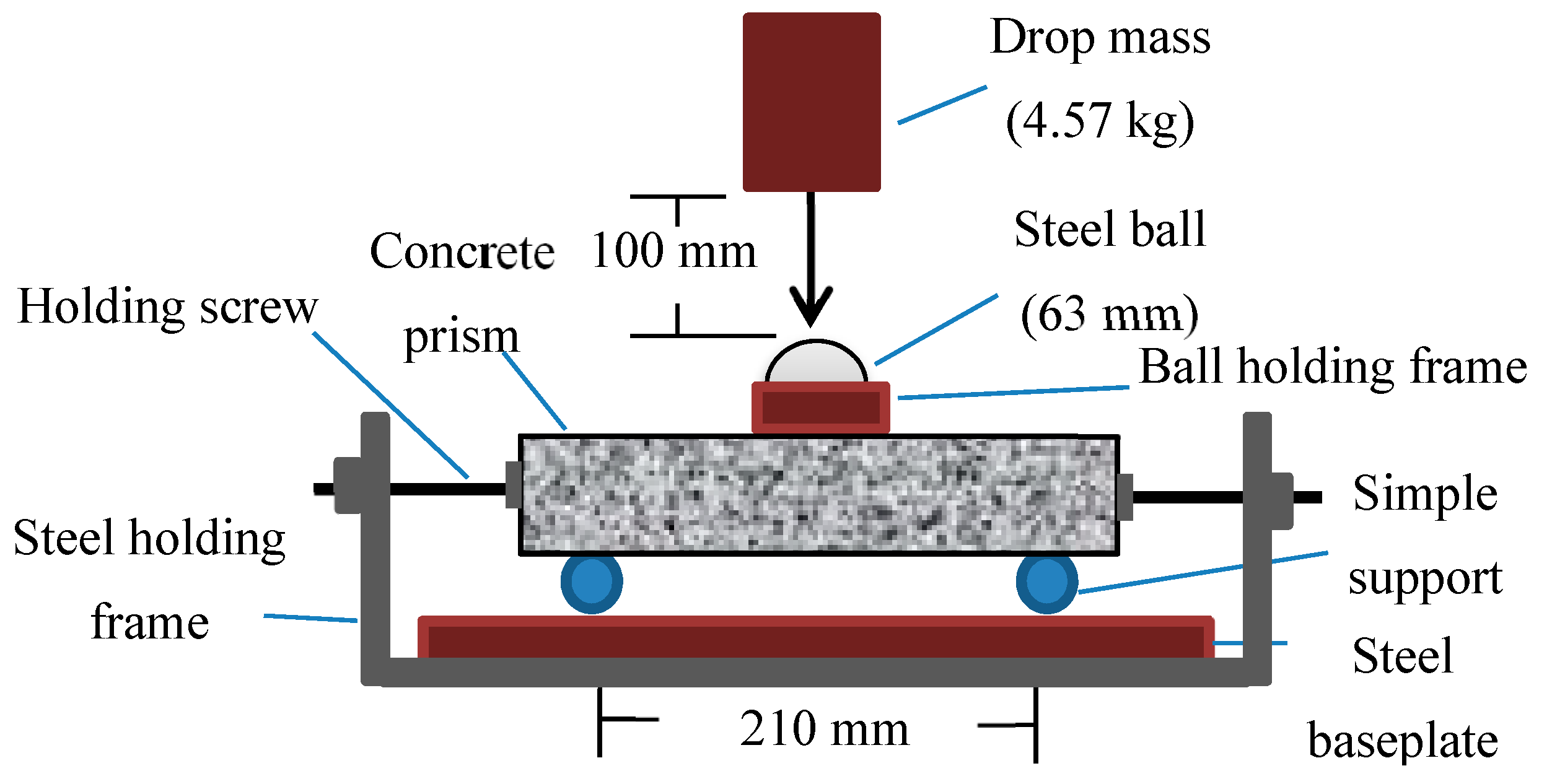
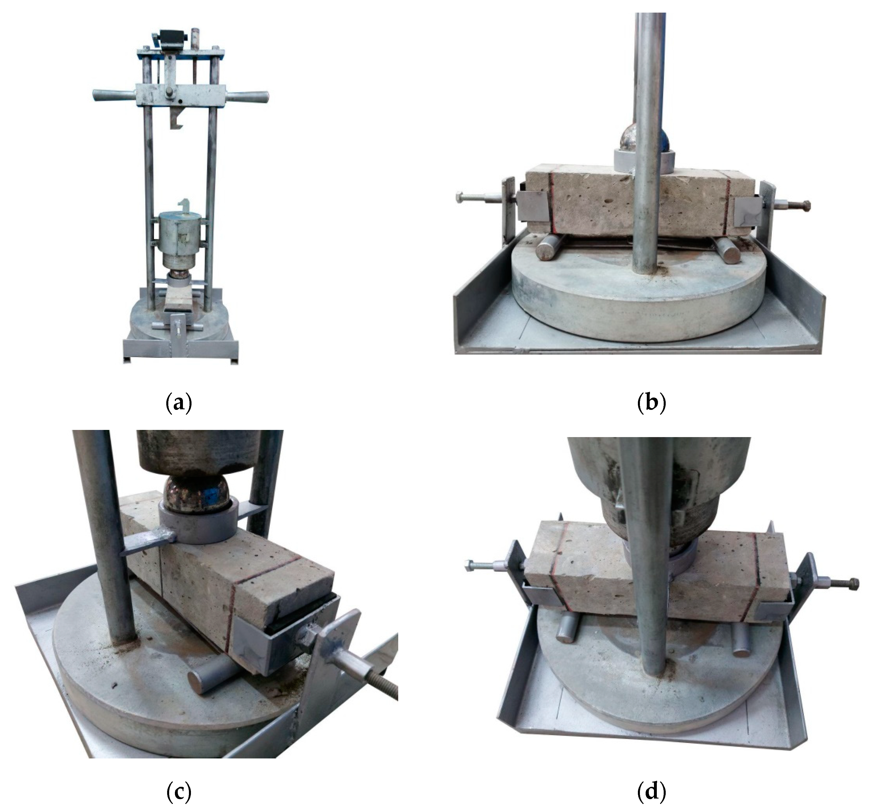
2. Materials and Methods

The ACI 363R-10 [36] adopted a compressive strength of 6 ksi (41.4 MPa) as a limit between normal and high strength concretes. The experimental study that was conducted comprised the preparing of eight mixtures of two groups with two concrete design strengths. The first was 30 MPa to represent normal strength concrete, while the second was 50 MPa to distinguish high strength concrete. Micro steel fiber was used in six mixtures to enhance their mechanical properties and impact energy absorption, while two mixtures were kept plain. For each of the two design strengths, four fiber contents of 0%, 0.5%, 0.75%, and 1.0% were used. Two types of specimens were used in this study. Prisms that have cross-section of 70 × 70 mm and length of 260 mm were tested on a simple span of 210 mm to perform the flexural impact test. Similar specimens were also used to obtain the static modulus of rupture, using the bending test on a span of 210 mm. At the same time, the compressive strength was tested using 70 mm cubes. Twelve identical prisms were used to carry out the impact and modulus of rupture tests and six cubes were used to obtain the compressive strength. All specimens were cured in temperature-controlled water curing tanks, until they were tested at an age of 28 days. The impact test was conducted using a free-falling mass of 4.57 kg, which was dropped repeatedly from a falling height of 100 mm, as illustrated in Figure 1. The conducted test followed the procedure of ACI 544-2R [14] repeated drop weight impact test, using a steel ball as a drop-load distributer. The steel ball has a diameter of approximately 63 mm and was positioned on the top surface of the prism at the center of the span, as shown in Figure 2. To prevent the rebound of the prism after each impact blow, steel holding screw bars with steel end-plates were used at the specimen’s cross-sectional ends. The used holding technique detailed in Figure 2 prevents the longitudinal and lateral movements and assures direct transfer of the impact force to the target specimen. The impact test requires recording the impact repetition (number of blows) that can initiate the first crack (Ncr) and the number of impact blows that causes the failure of the prism (Nf). The falling height was reduced to reduce the single impact energy so that the required impact repetition to crack or fail the specimens would be increased. Hence, the differences among the specimens of the eight groups would be clearer, which allow a better analysis to the effect of the parameters under investigation (design compressive strength and steel fiber content).
Excluding the silica fume that was used only with the 50 MPa mixtures, the same materials were used to produce the eight mixtures. Portland cement type R42.5 was used as the main binder for all mixtures. The used coarse aggregate was local crushed gravel with a maximum particle size of 12.5 mm and local sand was used as fine aggregates. Fixed quantity of limestone powder of 67 kg/m3 and different dosages of Sika ViscoCrete-5930 were used to improve the fresh properties of the adopted mixtures. The used micro-steel fiber was copper-coated straight fiber with a length of 15 mm and a diameter of 0.2 mm, while its tensile strength was 2600 MPa. The material quantities of the eight mixtures are shown in Table 1, while the sieve analysis of the two aggregate types is shown in Figure 3. The initial SC in the specimens’ identifications refers to self-compacting, which is followed by the concrete design grade (30 or 50), while the following number refers to the fiber content.

3. Results and Discussion

3.1. Compressive Strength and Modulus of Rupture
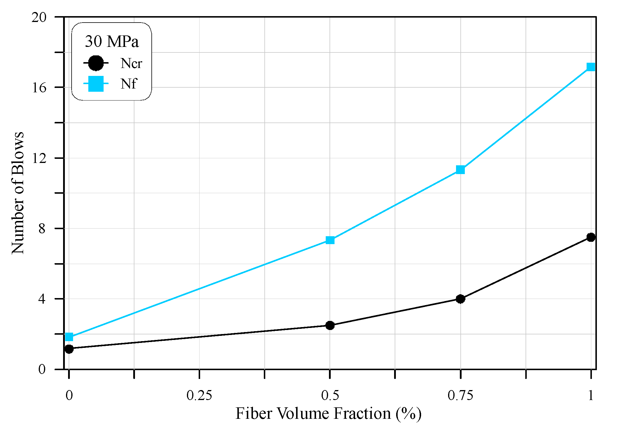
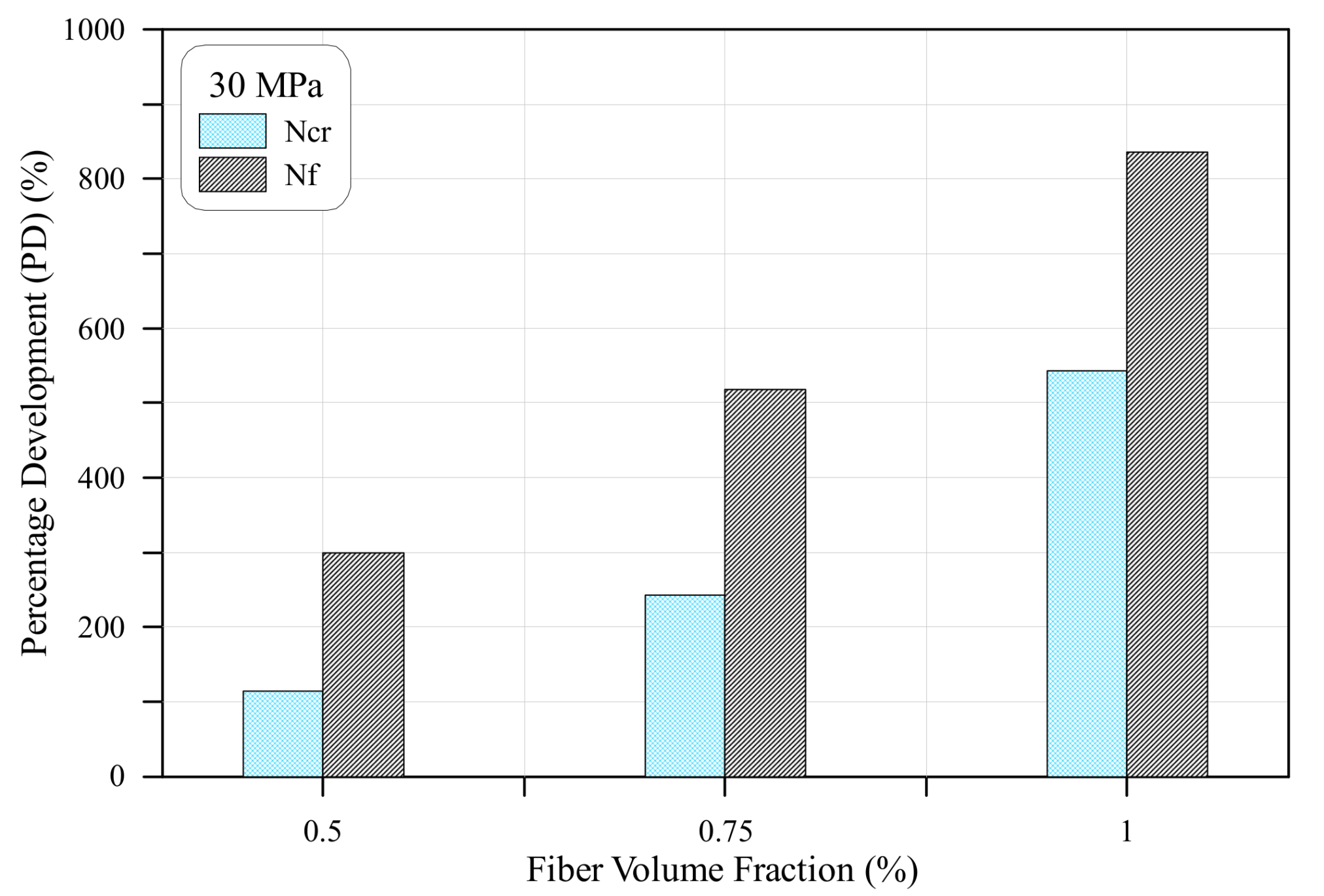
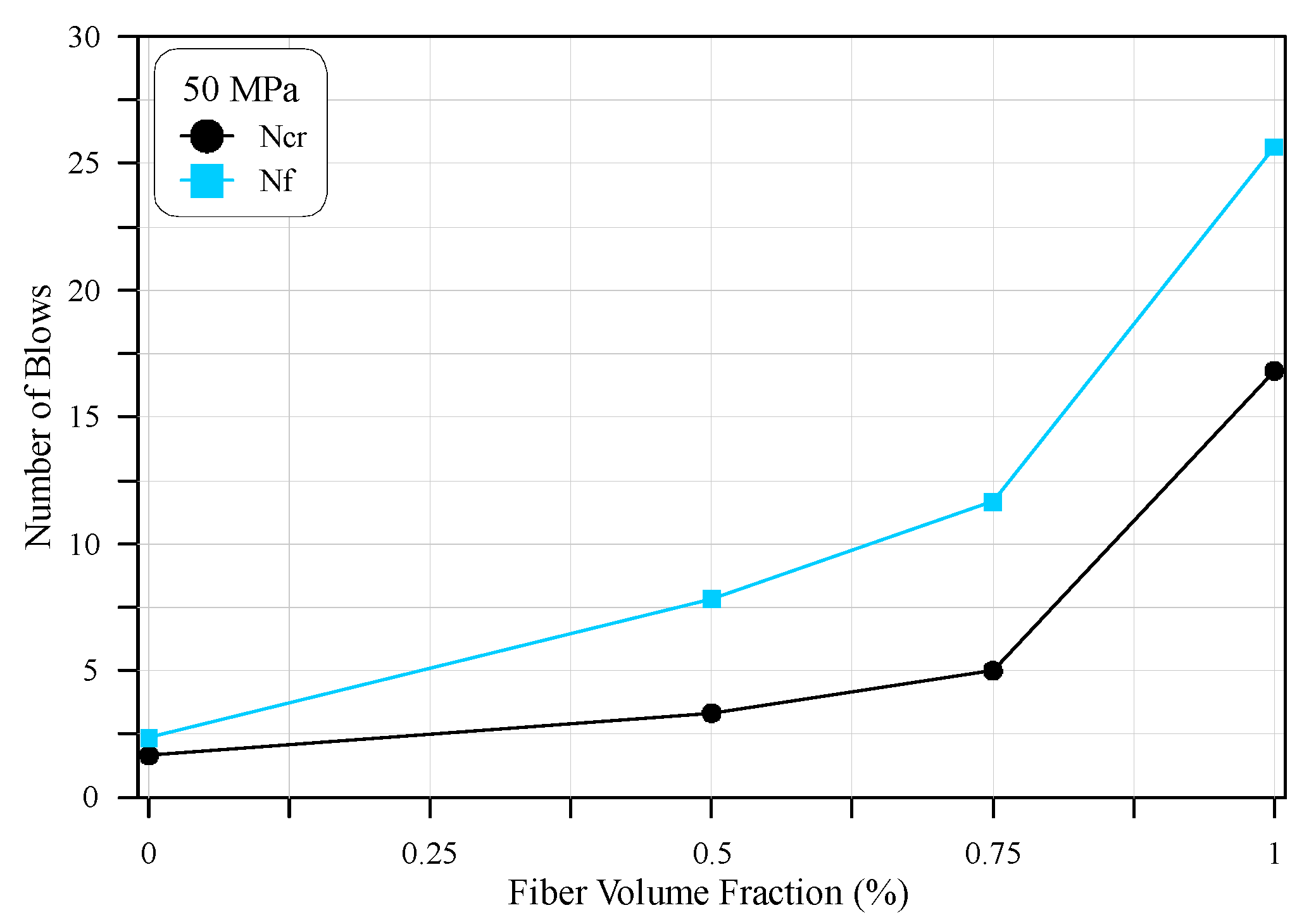
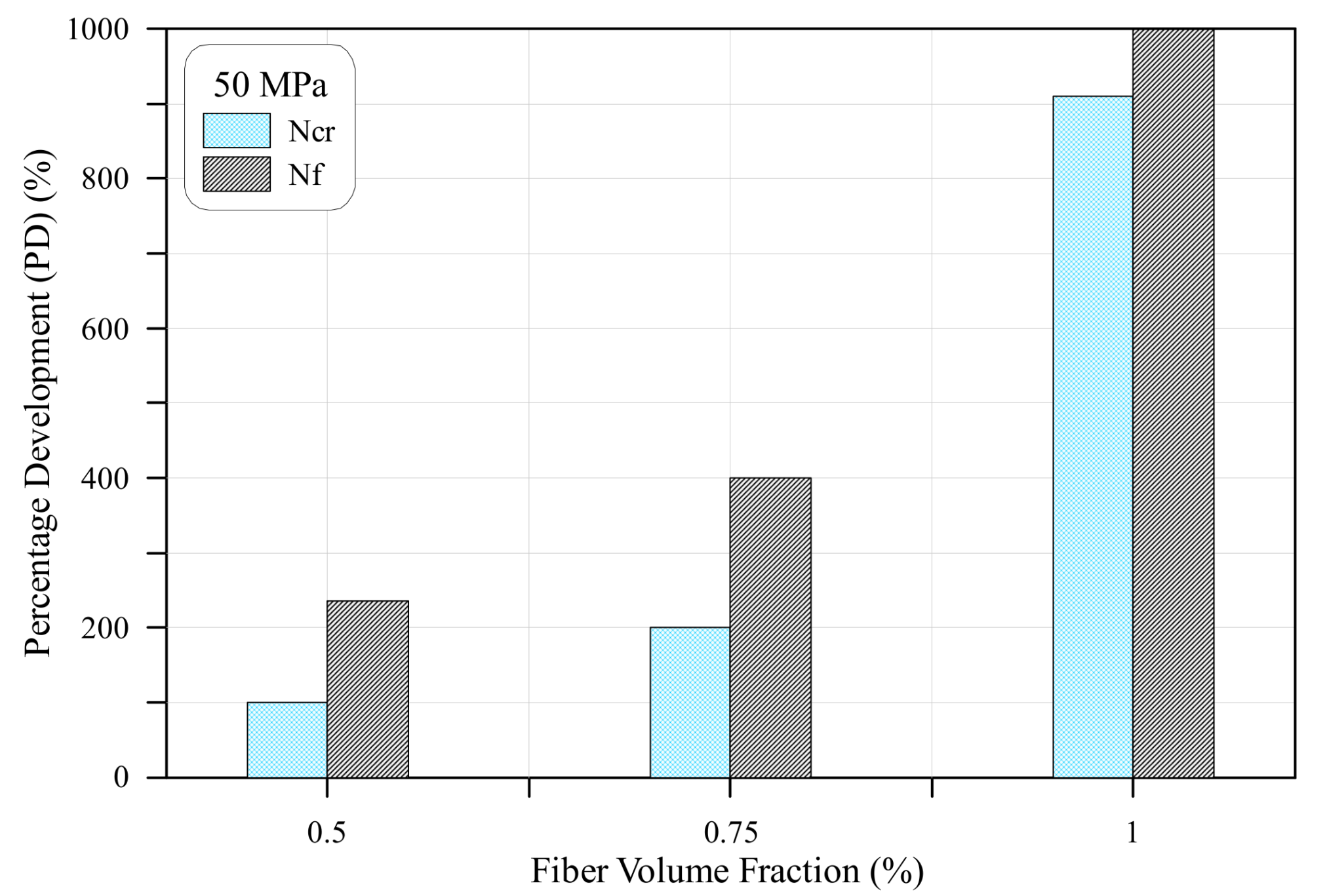
The compressive strength of cubes and modulus of rupture prisms are demonstrated in Table 2 for the eight mixtures. It was shown that the compressive strength of the 30 MPa design strength mixtures ranged from 51 to 56.5 MPa. These values were apparently higher than the basic design strength of the mixture, which was 30 MPa, due to the smaller used cubes, where the mix design depended on the 150 mm diameter standard cylinder, while this test was performed using 70 mm cubes in this study. Due to the same reason, those of the 50 MPa mixtures where noticeably higher than the design strength. Table 2 shows that the compressive strength of these mixtures ranges from 83.5 to 88.2 MPa. It can also be noticed that the fiber content had no distinguished effect on the compressive strength of the adopted mixtures, where there was no specific trend of increase or decrease of compressive strength with fiber content.
The modulus of rupture, which is an indirect indicator of concrete tensile strength, was strongly affected by fiber inclusion, where the modulus of rupture of mixtures containing 0.75% and 1.0% of steel fiber volumetric contents was noticeably higher than that of the plain specimens. For the 30 MPa mixtures, the modulus of rupture was increased by 26 and 42% when the fiber volume percentages of 0.75 and 1.0%, respectively, were used. However, it could be noticed that the inclusion of low content of 0.5% did not lead to any increase in the modulus of rupture. For the 50 MPa mixtures, the modulus of rupture increased as the fiber content increased. The percentage increases in the modulus of rupture for 0.5, 0.75, and 1.0% steel fibers were approximately 3, 17, and 34%, respectively. The increase in the modulus of rupture was attributed to the capability of fibers to bridge the formed cracks, allowing us to absorb higher loads until the bond between fibers and the concrete matrix was lost [37,38,39,40].

3.2. Impact Test

The experimental outcome of the impact beams is detailed in Table 3 and visualized in Figure 4, Figure 5, Figure 6 and Figure 7, for both the 30 and 50 MPa groups. Figure 4 shows the results of the repeated impact test of the 30 MPa specimens. The figure is presented for both the cracking number (Ncr) and the fracture number of blows (Nf). The figure apparently reveals that the number of blows increases as the content of steel fiber increases, both for Ncr and Nf. It should be reminded here that the numbers of blows shown in Figure 4 represent the average record of six specimens. The cracking number of blows increased from only 1.2 blows for plain concrete to 2.5, 4, and 7.5 blows for concretes with 0.5%, 0.75%, and 1.0% of steel fiber, respectively. Similarly, the failure number of blows was in the order of 1.8, 7.3, 11.3, and 17.2 blows for micro-steel fiber volume percentages of 0%, 0.5%, 0.75%, and 1.0%, respectively.
The influence of the adopted micro-steel fibers on impact capacity is shown in Figure 5 in terms of percentage development, as compared to the plain mixture that contains no fiber. These measurements are shown for both the cracking and failure numbers of impact blows. It is obvious in Figure 5 that the micro-steel fibers resulted in considerable improvements in the impact capacity at both first cracking and final fracture. However, this effect was more obvious at failure than at the cracking stage. The percentage developments due to the incorporation of 0.5%, 0.75%, and 1.0% of steel fiber were 114%, 243%, and 543%, respectively, at cracking, while they were 300%, 518%, and 836%, respectively, at failure. The high positive effect of steel fiber on impact resistance was due to the capability of fibers to bridge the initiated micro cracks due to the impact loading, which reflected the ability of the adopted micro-steel fibers to endure effective tensile stresses, to keep the two sides of the crack bonded. As a result, the recording of the first visual crack was delayed for several impact blows. As the cracks became continuous and visible, the tensile stress resistance by the fibers get larger after each single blow, while the two sides of the crack are still bridged by fibers. Consequently, the failure was postponed for several blows, ending by the breaking of the bond between the fibers concrete matrix, where the pullout of fibers was the most common recorded failure type [41,42]. Another possible type of failure is the breaking of fibers, which occurs when a sufficient bond is provided between the fibers and concrete matrix. Hence, the tensile strength of fibers is reached, while the bond shearing stresses are still lower than bond strength. The domination of bond failure in the current work was mostly due to fiber length (relatively short), which led to lower development lengths inside the matrix, across the cracks.
Figure 6 shows the impact results at the cracking and failure stages, in terms of number of blows for the 50 MPa mixtures. As for the 30 MPa mixtures, the steel fiber inclusion was very influential on impact resistance. The number of blows increased noticeably, as the fiber content increased. The number of repeated impacts required to crack the beams jumped from 1.6 for zero-fiber concrete to 3.3, 5, and 16.8 for the 0.5%, 0.75%, and 1.0% fiber contents, respectively. This meant, as shown in Figure 7, that the impact resistance was improved by 100%, 200%, and 910%, respectively, over the plain specimens. Similarly, the number of blows required to fail the beams increased from 2.3 for the plain beams to 7.8, 11.7, and 25.7 for beams including fiber contents of 0.5%, 0.75%, and 1.0%, respectively. Thus, the percentage development in impact resistance owing to the inclusion of 0.5%, 0.75%, and 1.0% micro-steel fibers were approximately 235%, 400%, and 1000%, respectively, as shown in Figure 7. As recorded for the 30 MPa beams (Figure 5), it is obvious in Figure 7 that the percentage developments were more evident at final fracture than at initial cracking. This result was attributed to the activity sequence of fibers with stress development, due to the impact loads. After the breaking of the mechanical interlock and friction bond components of concrete along the formed crack, fibers become more responsible for withstanding tensile stresses across this crack. Hence, increasing the difference between the cracking and failure number of blows compared to that of the plain specimens. On the other hand, fibers were only slightly stressed due to the internal matrix micro-cracks and were not in their full function before the first surface crack became visible.

3.3. Impact Ductility

Ductility in general is a measurement of the structural member ability to absorb plastic energy and withstand plastic deformations. Ductility is usually measured for flexural members as the deflection at failure, or at some other defined stress level along the post peak region, divided by the recorded deformation at yielding stage [37,40]. Hence, the failure plastic deformation divided by the maximum elastic deformation. Some previous studies [4,41] adopted a similar ductility definition to define the post-cracking ability of concrete to absorb impact energy, where the ratio of failure number of blows to the cracking number of blows was defined as impact ductility (DI). Using this definition, the impact ductility of the eight mixtures of this study were plotted; shown in Figure 7. The figure shows two major findings; the first was that the ductility of the 30 MPa beam specimens was in general higher than that of the 50 MPa beams for all fiber contents, while the second was that the impact ductility of beams with steel fibers was in general more than the impact ductility of zero-fiber beams. However, as shown in Figure 8, it was not assured that adding higher volumes of fiber resulted in higher impact ductility. The impact ductility was approximately 1.6 and 1.4 for the 30 and 50 MPa plain beams, respectively, while the impact ductility of fibrous beams was in the range of approximately 1.5 to 2.9. This result was expected, as it became known that fibers increase the absorbed energy after crack formation under tensile stresses, which increases the ability of absorbing higher plastic deformation, hence increasing the ductility [20,41,42,43].
To better discuss and compare the ductility of different concrete types, experimental records from the literature on flexural impact were utilized herein. Due to the different drop weights and drop heights adopted by the different research studies, the impact energy was used in this comparison, instead of the number of blows. Such measurement would assure a better and fairer comparison tool. The impact energy (Ei) was calculated for both the cracking and failure number of blows (N), using Equation (1), in which (h) is the drop height of the drop mass (w), while (ν) and (g) are the velocity at which the drop mass falls and gravity accelerates, respectively.
E i =   N w v 2 2 =   N w g h
Table 4 shows the details of the experimental records of flexural impact tests from Mohammadi et al. [30], Al-Tayeb et al. [31], and Noaman et al. [33], in addition to the test results obtained in this research. It is obvious that the impact energy ranges, both at cracking (Ecr) and at failure (EF) were dependent on the absorbed number of impacts, which was affected by the drop weight, drop height, beam size and span, in addition to the mixture constituents. Al-Tayeb et al. [31] showed that the utilization of crumb rubber could modify the impact absorbance capacity of concrete, which was reflected on the values of the retained numbers of impacts. However, the ductility of the mixture without crumb rubber was 3.54, which was the highest among all mixtures. This meant that recycled rubber could increase the impact resistance at the cracking stage by a similar or more amount than that at failure stage. This conclusion was also reinforced by the findings of Noaman et al. [33], where for the plain mixtures (no steel fiber), the impact ductility of the zero-rubber mixture was 1.67, while those of the rubberized mixtures were between 1.43 and 1.46. A similar sequence of results was obtained for the fibrous mixtures, where the mixture without crumb rubber retained a higher DI of 2.25, compared to no more than 1.7 for those with crumb rubber. Comparing the results of Noaman et al. [33], it was obvious that steel fiber could increase ductility, as concluded in this research, where the maximum ductility of the plain and fibrous mixtures were 2.25 and 1.67, respectively. This experimental finding was in good alignment with the results of Mohammadi et al. [30], as shown in Table 4, where high DI values were recorded for the mixtures containing steel fibers. The positive effect of steel fiber on ductility was ascribed to its function sequence, as discussed previously, where its post-cracking impact enhancement potential was noticeably higher than before cracking, which resulted in higher development in failure impact number, as compared to the cracking impact number, which consequently increased the ductility. The results of Mohammadi et al. [30] further supported this conclusion by a comparison between DI of the different fiber contents, where the maximum ductility increased as the fiber content increased, which were in the sequence of 5.35, 6.0, and 6.54 for 1.0%, 1.5%, and 2.0% steel fiber contents, respectively.

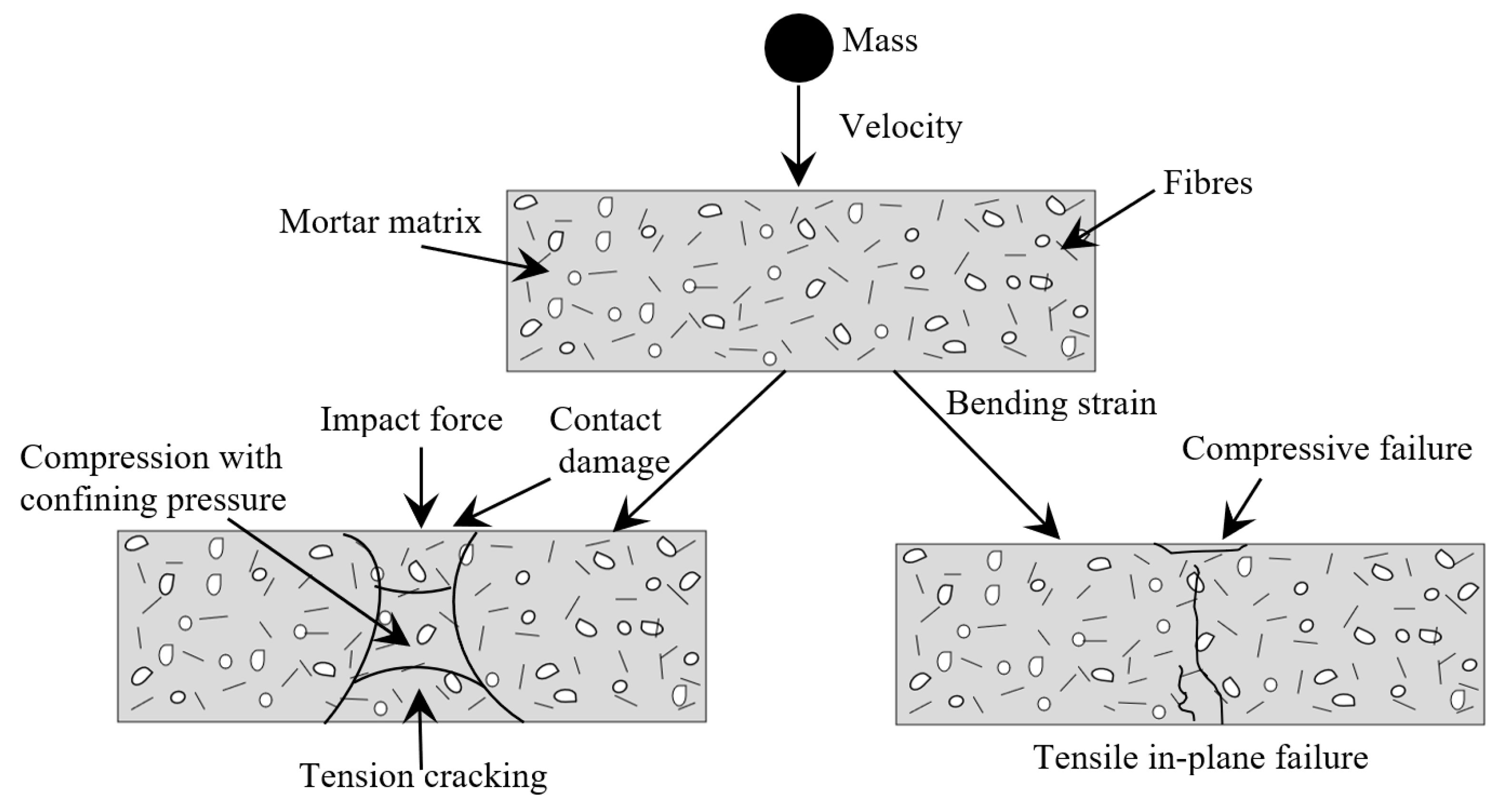
3.4. The Failure Mechanism of the Specimen under Drop Weight Impact

The schematic diagram of the specimen’s failure mechanism under impact load is depicted in Figure 9. The progression of failure mechanism is explained in four stages—(i) localized contact damage on the top surface of the specimen, due to the application of drop weight, (ii) matrix failure (iii), fiber failure, and (iv) fiber debonding [3]. The cement matrix damaged along the direction of impact force was called contact damage. Transverse shear stress/strain in the specimen resulted in inner debonding/matrix failure. The fiber/matrix failure resulted from compression bending on the impact plane. Fiber debonding occurred due to tensile bending at surface bottom. A tremendous amount of initial kinetic energy was transferred to the fiber, after the crack initiation. This demonstrated that the fibers tended to arrest cracks, and more energy was dissipated to the surrounding zones of concrete [44]. Henceforth, the failure mechanism’s vital juncture was fiber delamination, which caused negative consequences in strength properties. This phenomenon was tough enough to detect during the operation.

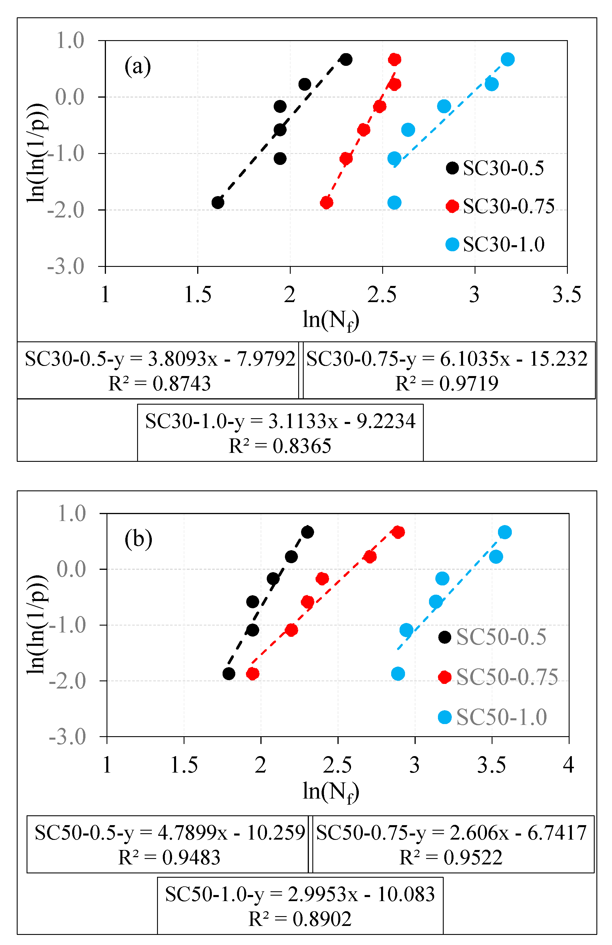
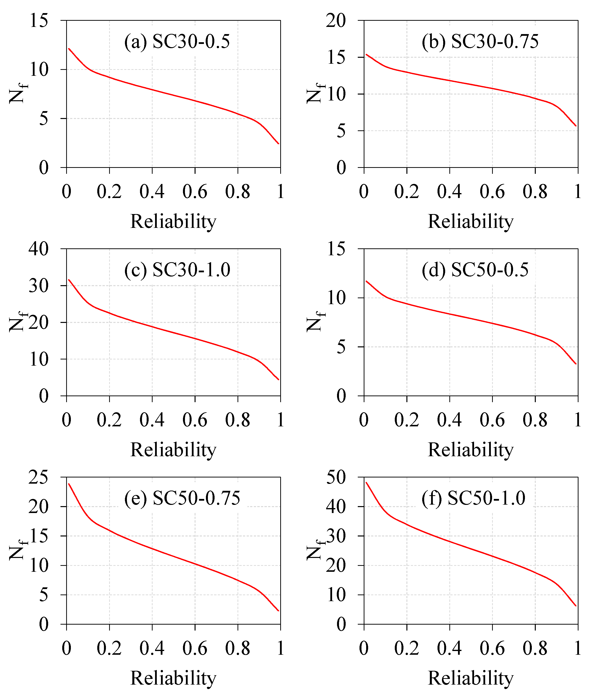
3.5. Distribution of Weibull

Several investigations reported that the ACI 544 [14] drop weight test is not reliable, and a minimum of six specimens per mixture should be tested [44,45]. Even though considerable effort was taken to establish identical testing conditions, the test results were distinct. Subsequently, a need arose to apply the statistical technique to analyze the dispersed drop weight test results. Earlier studies indicated that the drop weight test results complied with the Weibull distribution [19,46]. The Weibull distribution was introduced by Waloddi Weibull, who described the in-depth probability distribution [47]. With distribution of Weibull help, the minimum safety impact strength of concrete could be achieved and was realistic enough for practical design purposes. In the last few years, the distribution of Weibull was used frequently used to describe the impact strength of concrete [3,44,45,47]. In this research, the two-parameter Weibull distribution was applied to assess the impact strength of fibrous concretes in terms of different level of reliability. The observed variations in the number of impact blows at which the first crack had formed (Ncr), were significantly less, as compared to the number of impact blows that caused the failure of the prism (Nf). Moreover, the non-fibrous specimens exhibited fewer variations in Nf than the fibrous-specimens. Therefore, the Weibull distribution was performed only on fibrous specimens to analyze the Nf results. The scattered experimental drop weight test results could be analyzed by the two-parameter distribution of Weibull; the function of probability density is expressed in Equation (2) [4,41]:
f ( N f ) =   r N a N 0   [ N f N 0 N a N 0 ] r 1 e x p { [ N f N 0 N a N 0 ] r }   ( N 0 N f < )
where Na is the scale parameter of Nf, r is the shape parameter, N0 is the safety of Nf at the level of the minimum, and Nf is a Weibull variable. The distribution function (N) was obtained by deriving Equation (2) and is denoted in Equation (3) [41]:
F ( N p ) = P ( N f < N p ) = 1 e x p { [ N p N 0 N a N ] r }
P is the failure probability (Nf < N), then:
P ( N f > N p ) = 1 P ( N f < N p ) = e x p { [ N p N 0 N a N ] r }
From Equation (4), if r, Na, and N0 are known in a range of particular survival rate P, this contributes to finding N. Since the Nf of concrete is diverse, the N0 value for the concrete is considered to be 0 [48]. Consequently, simplifying Equation (2) into the Weibull function can be expressed as follows:
f ( Z f ) =   r N a   [ N f N a ] r 1 e x p { [ N f N a ] r }   ( N 0 N f < )
The survival possibility P and the failure probability could be articulated as follows:
p = e x p { [ N f N a ] r }
p = 1 p = 1 e x p { [ N f N a ] r }
Taking a function of natural logarithm on each side of Equation (7), the obtained formula can be expressed in Equation (8):
l n [ l n ( 1 p ) ] = r l n N f b l n N a
When reorganizing Equation (8) as a linear equation, it can be expressed below as,
Y =   l n [ l n ( 1 p ) ] = l n [ l n ( 1 p ) ]   ,   X =   l n N f ,   a = r l n N a , the Equation (8) could be expressed as follows:
Y = r X a
The above Equation (9) delivers a number of impact blows that causes the failure (Nf), which is well-defined by two parameters of Weibull. An easy linear regression model was performed on the drop weight experimental test results to obtain the Weibull parameters. If the linear relationship between X and Y is good, it indicates that the tested results follow the Weibull two-parameter distribution. Using Equation (10), the relationship between Nf and p can be determined as [49]:
p = 1 e h + 1
where e is the number of specimens tested per mix, arranged in ascending order, and h is the overall amount of testing data.
A graphical representation of ln[ln(1/p)] in the y-axis and every number of impact blows that causes the failure (Nf) in the x-axis is shown in Figure 10. If the test point’s relationship is linear, it is expected that the Nf follows the Weibull distribution. The linear regression slope describes the shape parameter, which can be found directly; whereas the scale parameter is determined using Equation (11), expressed as follows:
N a = e ( a / r )
The number of impact blows that causes failure (Nf) in terms of the different levels of reliability is determined from the parameters of Weibull, using Equation (12) [16,50].
N = N a ( l n ( R x ) ( 1 / r )
where Rx is the required level of reliability function.
The determined Weibull parameters from the linear regression model of the tested fibrous specimens are demonstrated in Table 5, in which it is obvious that the coefficient of determination (R2) of the tested specimens hit values greater than 0.83 to 0.97. This confirms the good linear relationship between the X and Y data. In a nutshell, the number of impact blows that cause the failure (Nf), follows the two-parameter Weibull distribution.
The number of impact blows that causes the failure of the prism (Nf) in terms of different levels of reliability, is illustrated in Figure 11. By taking the 0.9 reliability level from Figure 11a–c, the Nf values for the SC30-0.5, SC30-0.75, and SC30-1.0 specimens were 4, 8, and 9, respectively. Likewise, the Nf values were found to be 5, 6, and 14 for the SC50-0.5, SC50-0.75, and SC50-1 specimens, as shown in Figure 11d–f. Reliability analysis with the distribution of Weibull could be utilized prudently to analyze the dispersed experimental test results. This statistical tool eradicates the cost and the time to conduct the experimental drop weight test on specimens [47,48,49,50,51,52]. A structural design engineer could select the appropriate Nf value required for the design requirements from the developed reliability–Nf curves.

4. Conclusions

Repeated flexural drop-weight impact tests were carried out in this research study, on self-compacting concrete reinforced with micro-steel fibers. The concrete was made of two design grades of 30 and 50 MPa with 0%, 0.5%, 0.75%, and 1.0% volume content of steel fibers. In light of the test records of this research, the conclusions could be addressed as follows.
1—Steel fibers have a distinguishable positive effect on pre-cracking and post-cracking impact capacities of beams tested in flexural impact, where the impact resistance increased as the fiber content increased. For instance, the retained numbers of impact blows at cracking for the 50 MPa specimens with fiber contents of 0%, 0.5%, 0.75%, and 1.0% were 1.6%, 3.3%, 5%, and 16.8%, respectively. This significant positive effect was ascribed to the fibers ability to enhance the tensile and flexural responses under loading, which was mainly due to the fiber’s ability to absorb high bridging tensile stresses across the two faces of the formed cracks.
2—Due to the functionality of fibers as an efficient crack bridging reinforcement, its post cracking (failure stage) activity was much higher than the pre-cracking (cracking stage) activity. For the 30 MPa specimens as an example, the percentage increases in cracking impact resistance over plain specimens were 114%, 243%, and 543% for the fiber contents of 0.5%, 0.75%, and 1.0%, respectively, while these percentages were 300%, 518%, and 836%, respectively, at the failure stage.
3—The impact ductility was the ratio of failure number of blows to cracking number of blows, which was higher for the fibrous specimens than the plain specimens, where it ranged from approximately 1.4 to 1.6 for the plain specimens and from approximately 1.5 to 2.9 for the fibrous specimens. This was also ascribed to the greater tensile stress absorbance capacity of the fibrous specimens after crack formation.
4—The fibrous specimen’s data points were linearly correlated, where the number of impact blows that caused the failure of the prism was established to obey the distribution of Weibull. The Weibull distribution eradicated cost and time required to conduct the experimental test. Using the developed reliability curves, the structural design engineer can have an option of choosing suitable impact energy value for the design requirements.

Author Contributions

Conceptualization, S.R.A. and T.S.A.-G.; methodology, S.H.A., A.L.K., and T.S.A.-G.; software, M.G. and M.K.; validation, S.R.A., M.G., and R.F.; formal analysis, M.G. and N.V.; investigation, S.R.A. and T.S.A.-G.; resources, S.R.A., S.H.A., A.L.K., and T.S.A.-G.; data curation, T.S.A.-G. and M.K.; writing—original draft preparation, S.R.A. and M.G.; writing—review and editing, R.F., N.V. and M.K.; visualization, S.R.A., M.G. and S.H.A.; supervision, S.R.A.; project administration, S.R.A. and T.S.A.-G.; funding acquisition, R.F., M.K., and N.V. All authors have read and agreed to the published version of the manuscript.

Funding

The research is partially funded by the Ministry of Science and Higher Education of the Russian Federation as part of World-class Research Center program: Advanced Digital Technologies (contract No. 075-15-2020-934 dated 17 November 2020).

Institutional Review Board Statement

Not applicable.

Informed Consent Statement

Not applicable.

Data Availability Statement

Data can be shared upon direct request.

Acknowledgments

The authors would like to express their gratitude for the technical support of the Construction Materials Laboratory staff in Wasit University/College of Engineering/Civil Engineering Department.

Conflicts of Interest

The authors declare no conflict of interest.

References

  1. Nili, M.; Afroughsabet, V. Combined effect of silica fume and steel fibers on the impact resistance and mechanical properties of concrete. Int. J. Impact Eng. 2010, 37, 879–886. [Google Scholar] [CrossRef] [Green Version]
  2. Wang, W.; Chouw, N. The behavior of coconut fibre reinforced concrete (CFRC) under impact loading. Constr. Build. Mater. 2017, 134, 452–461. [Google Scholar] [CrossRef]
  3. Abirami, T.; Murali, G.; Mohan, K.S.R.; Salaimanimagudam, M.P.; Nagaveni, P.; Bhargavi, P. Multi-layered two stage fibrous composites against low-velocity falling mass and projectile impact. Const. Build. Mater. 2020, 248, 118631. [Google Scholar] [CrossRef]
  4. Abirami, T.; Loganaganandan, M.; Murali, G.; Fediuk, R.; Sreekrishna, R.V.; Vignesh, T.; Januppriya, G.; Karthikeyan, K. Experimental research on impact response of novel steel fibrous concretes under falling mass impact. Constr. Build. Mater. 2019, 222, 447–457. [Google Scholar] [CrossRef]
  5. Abid, S.R.; Shamkhi, M.S.; Mahdi, N.S.; Daek, Y.H. Hydro-abrasive resistance of engineered cementitious composites with PP and PVA fibers. Constr. Build. Mater. 2018, 187, 168–177. [Google Scholar] [CrossRef]
  6. Ayoob, N.S.; Abid, S.R.; Hilo, A.N. Water-impact abrasion of self-compacting concrete. Mag. Civ. Eng. 2020, 96, 60–69. [Google Scholar]
  7. Ali, S.H.; Ayoob, N.S.; Abdul-Hussein, M.L.; Abid, S.R. Water impact-abrasion erosion of hybrid fiber-reinforced high performance concrete. Nano Hybrids Compos. 2020, 30, 63–72. [Google Scholar] [CrossRef]
  8. Pan, Y.; Wu, C.; Cheng, X.; Li, V.C.; He, L. Impact fatigue behaviour of GFRP mesh reinforced engineered cementitious composites for runway pavement. Constr. Build. Mater. 2020, 230, 116898. [Google Scholar] [CrossRef]
  9. Wang, S.; Le, H.T.N.; Poh, L.H.; Feng, H.; Zhang, M.-H. Resistance of high-performance fiber-reinforced cement composites against high-velocity projectile impact. Int. J. Impact Eng. 2016, 95, 89–104. [Google Scholar] [CrossRef]
  10. Luccioni, B.; Isla, F.; Codina, R.; Ambrosini, D.; Zerbino, R.; Giaccio, G.; Torrijos, M.C. Effect of steel fibers on static and blast response of high strength concrete. Int. J. Impact Eng. 2017, 107, 23–27. [Google Scholar] [CrossRef] [Green Version]
  11. Yoo, D.-Y.; Banthia, N. Mechanical and structural behaviors of ultra-high-performance fiber-reinforced concrete subjected to impact and blast. Constr. Build. Mater. 2017, 149, 416–431. [Google Scholar] [CrossRef]
  12. Kim, G.-Y.; Choi, J.; Park, S.-E.; Kim, H.; Lee, Y.; Lee, B.Y. Response of UHPFRC and HDFRC under static and high-velocity projectile impact loads. Constr. Build. Mater. 2018, 188, 399–408. [Google Scholar] [CrossRef]
  13. Feng, J.; Gao, X.; Li, J.; Dong, H.; He, Q.; Dong, H.; Liang, J.; Sun, W. Penetration resistance of hybrid-fiber-reinforced high-strength concrete under projectile multi-impact. Constr. Build. Mater. 2019, 202, 341–352. [Google Scholar] [CrossRef]
  14. ACI 544.2R-89. Measurement of Properties of Fiber Reinforced Concrete; American Concrete Institute ACI: Farmington Hills, MI, USA, 1999. [Google Scholar]
  15. Abid, S.R.; Abdul-Hussein, M.L.; Ali, S.H.; Kazem, A.F. Suggested modified testing techniques to the ACI 544-R repeated drop-weight impact test. Constr. Build. Mater. 2020, 244, 118321. [Google Scholar] [CrossRef]
  16. Murali, G.; Chandana, V. Weibull reliability analysis of impact resistance on self-compacting concrete reinforced with recycled CFRP pieces. Rom. J. Mater. 2017, 47, 196–203. [Google Scholar]
  17. Song, P.S.; Wu, J.C.; Hwang, S.; Sheu, B.C. Assessment of statistical variations in impact resistance of high-strength concrete and high-strength steel fiber-reinforced concrete. Cem. Concr. Res. 2005, 35, 393–399. [Google Scholar] [CrossRef]
  18. Ismail, M.K.; Hassan, A.A. Impact resistance and mechanical properties of self-consolidating rubberized concrete reinforced with steel fibers. ASCE J. Mater. Civ. Eng. 2017, 29, 1–14. [Google Scholar] [CrossRef]
  19. Ding, Y.; Li, D.; Zhang, Y.; Azevedo, C. Experimental investigation on the composite effect of steel rebars and macro fibers on the impact behavior of high performance self-compacting concrete. Constr. Build. Mater. 2017, 136, 495–505. [Google Scholar] [CrossRef] [Green Version]
  20. Abid, S.R.; Abdul-Hussein, M.L.; Ayoob, N.S.; Ali, S.H.; Kadhum, A.L. Repeated drop-weight impact tests on self-compacting concrete reinforced with micro-steel fiber. Heliyon 2020, 6, 1–11. [Google Scholar] [CrossRef] [Green Version]
  21. Bard, A.; Ashour, A.F.; Platten, A.K. Statistical variations in impact resistance of polypropylene fiber-reinforced concrete. Int. J. Impact Eng. 2006, 32, 1907–1920. [Google Scholar] [CrossRef] [Green Version]
  22. Nili, M.; Afroughsabet, V. The effects of silica fume and polypropylene fibers on the impact resistance and mechanical properties of concrete. Constr. Build. Mater. 2010, 24, 927–933. [Google Scholar] [CrossRef]
  23. Mastali, M.; Dalvand, A.; Sattarifard, A. The impact resistance and mechanical properties of reinforced self-compacting concrete with recycled glass fiber reinforced polymers. J. Clean Produc. 2016, 124, 312–324. [Google Scholar] [CrossRef]
  24. Mastali, M.; Dalvand, A. The impact resistance and mechanical properties of self-compacting concrete reinforced with recycled CFRP pieces. Compos. B Eng. 2016, 92, 360–376. [Google Scholar] [CrossRef]
  25. Abdel Aleem, B.H.; Ismail, M.K.; Hassan, A.A. The combined effect of crumb rubber and synthetic fibers on impact resistance of self-consolidating concrete. Constr. Build. Mater. 2018, 162, 816–829. [Google Scholar] [CrossRef]
  26. Zhu, D.; Gencoglu, M.; Mobasher, B. Low velocity flexural impact behavior of AR glass fabric reinforced composites. Cem. Concr. Compos. 2009, 31, 379–387. [Google Scholar] [CrossRef]
  27. Rao, M.C.; Bhattacharyya, S.K.; Barai, S.V. Behaviour of recycled aggregate concrete under drop weight impact load. Constr. Build. Mater. 2011, 25, 69–80. [Google Scholar] [CrossRef]
  28. Dey, V.; Bonakdar, A.; Mobasher, B. Low-velocity flexural impact response of fiber-reinforced aerated concrete. Cem. Concr. Compos. 2014, 49, 100–110. [Google Scholar] [CrossRef]
  29. Zanuy, C.; Ulzurrun, G.S.D. Rate effects of fiber-reinforced concrete specimens in impact regime. Procedia Eng. 2017, 193, 501–508. [Google Scholar] [CrossRef]
  30. Mohammadi, Y.; Carkon-Azad, R.; Singh, S.P.; Kaushik, S.K. Impact resistance of steel fibrous concrete containing fibers of mixed aspect ratio. Constr. Build. Mater. 2009, 23, 183–189. [Google Scholar] [CrossRef]
  31. Al-Tayeb, M.M.; Abu Bakar, B.H.; Ismail, H.; Akil, H.M. Impact resistance of concrete with partial replacements of sand and cement by waste rubber. Polym. Plast. Technol. Eng. 2012, 51, 1230–1236. [Google Scholar] [CrossRef]
  32. Zhang, W.; Chen, S.; Zhang, N.; Zhou, Y. Low-velocity flexural impact response of steel fiber reinforced concrete subjected to freeze-thaw cycles in NaCl solution. Constr. Build. Mater. 2015, 101, 522–526. [Google Scholar] [CrossRef]
  33. Noaman, A.T.; Abu Bakar, B.H.; Akil, H.M. The effect of combination between crumb rubber and steel fiber on impact energy of concrete beams. Procedia Eng. 2015, 125, 825–831. [Google Scholar] [CrossRef] [Green Version]
  34. Zhang, W.; Chen, S.; Liu, Y. Effect of weight and drop height of hammer on the flexural impact performance of fiber-reinforced concrete. Constr. Build. Mater. 2017, 140, 31–35. [Google Scholar] [CrossRef]
  35. Abid, S.R.; Hilo, A.N.; Ayoob, N.S.; Daek, Y.H. Underwater abrasion of steel fiber-reinforced self-compacting concrete. Case Stud. Constr. Mater. 2019, 11, e00299. [Google Scholar] [CrossRef]
  36. ACI 363.R-10. Report on High-Strength Concrete; American Concrete Institute ACI: Farmington Hills, MI, USA, 2010. [Google Scholar]
  37. Abbass, A.A.; Abid, S.R.; Arnaot, F.H.; Al-Ameri, R.A.; Özakça, M. Flexural response of hollow high strength concrete beams considering different size reductions. Structures 2019, 23, 69–86. [Google Scholar] [CrossRef]
  38. Abid, S.R.; Murali, G.; Amran, M.; Vatin, N.; Fediuk, R.; Karelina, M. Evaluation of Mode II Fracture Toughness of Hybrid Fibrous Geopolymer Composites. Materials 2021, 14, 349. [Google Scholar] [CrossRef] [PubMed]
  39. Yoo, D.-Y.; Moon, D.-Y. Effect of steel fibers on the flexural behavior of RC beams with very low reinforcement ratios. Constr. Build. Mater. 2018, 188, 237–254. [Google Scholar] [CrossRef]
  40. Abbass, A.; Abid, S.; Özakça, M. Experimental investigation on the effect of steel fibers on the flexural behavior and ductility of high-strength concrete hollow beams. Adv. Civ. Eng. 2019, 2019, 1–13. [Google Scholar] [CrossRef]
  41. Haridharan, M.K.; Matheswaran, S.; Murali, G.; Abid, S.R.; Fediuk, R.; Amran, Y.H.; Abdelgader, H.S. Impact response of two-layered grouted aggregate fibrous concrete composite under falling mass impact. Constr. Build. Mater. 2020, 263, 120628. [Google Scholar] [CrossRef]
  42. Salaimanimagudam, M.P.; Suribabu, C.R.; Murali, G.; Abid, S.R. Impact response of hammerhead pier fibrous concrete beams designed with topology optimization. Period. Polytechnol. Civ. Eng. 2020, 64, 1244–1258. [Google Scholar] [CrossRef]
  43. Murali, G.; Abid, S.R.; Abdelgader, H.S.; Amran, M.; Shekarchi, M.; Wilde, K. Repeated Projectile Impact Tests on Multi-Layered Fibrous Cementitious Composites. Int. J. Civ. Eng. 2021, 1–17. [Google Scholar] [CrossRef]
  44. Asrani, N.P.; Murali, G.; Parthiban, K.; Surya, K.; Prakash, A.; Rathika, K.; Chandru, U. A feasibility of enhancing the impact resistance of hybrid fibrous geopolymer composites: Experiments and modeling. Constr. Build. Mater. 2019, 203, 56–68. [Google Scholar] [CrossRef]
  45. Murali, G.; Asrani, N.P.; Ramkumar, V.R.; Siva, A.; Haridharan, M.K. Impact resistance and strength reliability of novel two-stage fibre-reinforced concrete. Arab. J. Sci. Eng. 2019, 44, 4477–4490. [Google Scholar] [CrossRef]
  46. Chen, X.-Y.; Ding, Y.-N.; Azevedo, C. Combined effect of steel fibres and steel rebars on impact resistance of high-performance concrete. J. Cent. South Univ. 2011, 18, 1677–1684. [Google Scholar] [CrossRef] [Green Version]
  47. Amran, M.; Fediuk, R.; Vatin, N.; Lee, Y.H.; Murali, G.; Ozbakkaloglu, T.; Klyuev, S.; Alabduljabber, H. Fibre-reinforced foamed concretes: A review. Materials 2020, 13, 4323. [Google Scholar] [CrossRef]
  48. Murali, G.; Gayathri, R.; Ramkumar, V.R.; Karthikeyan, K. Two statistical scrutinize of impact strength and strength reliability of steel fibre-reinforced concrete. KSCE J. Civ. Eng. 2018, 22, 257–269. [Google Scholar] [CrossRef]
  49. Murali, G.; Indhumathi, T.; Karthikeyan, K.; Ramkumar, V.R. Analysis of flexural fatigue failure of concrete made with 100% coarse recycled and natural aggregates. Comput. Concr. 2018, 21, 291–298. [Google Scholar] [CrossRef]
  50. Murali, G.; Abid, S.R.; Amran, Y.H.M.; Abdelgader, H.S.; Fediuk, R.; Susrutha, R.; Poonguzhali, K. Impact performance of novel multi-layered prepacked aggregate fibrous composites under compression and bending. Structrues 2020, 28, 1502–1515. [Google Scholar] [CrossRef]
  51. Jabir, H.A.; Abid, S.R.; Murali, G.; Ali, S.H.; Klyuev, S.; Fediuk, R.; Vatin, N.; Promakhov, V.; Vasilev, Y. Experimental tests and reliability analysis of the cracking impact resistance of UHPFRC. Fibers 2020, 8, 74. [Google Scholar] [CrossRef]
  52. Prasad, N.; Murali, G. Exploring the impact performance of functionally-graded preplaced aggregate concrete incorporating steel and polypropylene fibres. J. Build. Eng. 2021, 35, 102077. [Google Scholar] [CrossRef]
Figure 1. Drop-weight impact test of the concrete prism.
Crystals 11 00091 g001
Figure 2. Repeated impact testing apparatus: (a) Appearance of testing device, (b) Specimen holder and support, (c) Appearance of channel section to prevent lateral movement and (d) Three-dimensional view of specimen and holding arrangement.
Crystals 11 00091 g002
Figure 3. Grading of the sand and crushed gravel.
Crystals 11 00091 g003
Figure 4. Number of cracking and failure impact blows for 30 MPa mixtures with different fiber contents.
Crystals 11 00091 g004
Figure 5. Percentage development (PD) in impact capacity due to micro-steel fibers of the 30 MPa mixtures.
Crystals 11 00091 g005
Figure 6. Number of cracking and failure impact blows for 50 MPa mixtures with different fiber contents.
Crystals 11 00091 g006
Figure 7. Percentage development (PD) in impact capacity due to micro-steel fibers of the 50 MPa mixtures.
Crystals 11 00091 g007
Figure 8. Impact ductility index for different fiber contents.
Crystals 11 00091 g008
Figure 9. Mechanism of failure.
Crystals 11 00091 g009
Figure 10. The Weibull lines: (a) SC30 series specimens and (b) SC50 series specimens.
Crystals 11 00091 g010
Figure 11. Impact strength in terms of reliability level: (a) SC30-0.5, (b) SC30-0.75, (c) SC30-1.0, (d) SC50-0.5, (e) SC50-0.75 and (f) SC50-1.0.
Crystals 11 00091 g011
Table 1. Mix proportions of the eight mixtures.
Material (kg/m3)SC30-0SC30-0.5SC30-0.75SC30-1.0SC50-0SC50-0.5SC50-0.75SC50-1.0
Cement392412412417525525525525
Sand1039106310631052907907931931
Gravel574503503468518518486486
Silica fume----67676767
Water181.3190190204190209209209
S.P.9.3131314.317171717
Fiber03958.57803958.578
Table 2. Outcome of experiments from the compressive strength and modulus of rupture tests.
VfCompressive Strength
(MPa)
Modulus of Rupture
(MPa)
SC30SC50SC30SC50
054.983.55.576.06
0.55185.75.356.22
0.7556.584.97.027.11
155.688.27.938.1
Table 3. Drop weight test results.
MixtureNSpecimen NumberMeanSDCOV
123456
SC30-0Ncr1111121.20.435
Nf1122231.80.841.1
SC30-0.5Ncr2223332.50.521.9
Nf57778107.31.622.3
SC30-0.75Ncr33444641.127.4
Nf9101112131311.31.614.4
SC30-1.0Ncr566710117.52.432.4
Nf13131417222417.24.827.9
SC50-0Ncr1122221.70.531
Nf2222332.30.522.1
SC50-0.5Ncr2334443.30.824.5
Nf67789107.81.518.8
SC50-0.75Ncr24457852.243.8
Nf791011151811.74.135
SC50-1.0Ncr8121414252816.87.946.7
Nf18192324343625.77.629.6
Table 4. Impact ductility records from the literature and current research.
ResearchMohammadi et al., 2009 [30]Al-Tayeb et al., 2010 [31]Noaman et al., 2015 [33]Current Research
Drop Height457900170100
Drop Weight5.545.155.14.57
Beam Section100 × 100100 × 100100 × 10070 × 70
Beam Span400400400210
Ecr79–178621–127543–3305–75
EF378–11612176–290679–5598–115
DI4.58–6.542.28–3.541.43–2.251.4–2.93
Table 5. The obtained Weibull parameters.
MixturerNaInterceptR2
SC30-0.53.8098.12−7.980.8502
SC30-0.756.13112.00−15.230.9719
SC30-1.03.11319.35−9.2230.8365
SC50-0.54.7908.51−10.2590.9483
SC50-0.752.60613.29−6.7420.9522
SC50-1.02.99528.97−10.0830.8902
Publisher’s Note: MDPI stays neutral with regard to jurisdictional claims in published maps and institutional affiliations.

