Article

Effect of Metal Powder Characteristics on Structural Defects of Graphene Nanosheets in Metal Composite Powders Dispersed by Ball Milling

1
State Key Laboratory of Solidification Processing, Northwestern Polytechnical University, Xi’an 710072, China
2
Joining & Welding Research Institution, Osaka University, 11-1 Mihogaoka, Ibaraki, Osaka 565-0047, Japan
*
Author to whom correspondence should be addressed.
Submission received: 31 January 2021 / Revised: 28 February 2021 / Accepted: 1 March 2021 / Published: 6 March 2021
(This article belongs to the Special Issue Thermomechanical Processing and Microstructure Control of Ti Alloys)

Abstract

:
Ball milling (BM) is the prime method to disperse graphene into metal powders; however, it inevitably introduces structural defects to graphene. The balance between dispersion quality and structural damage of graphene during BM is a significant issue for fabricating graphene/metal composite powders. In this study two metal powder characteristics, namely type and size, were investigated to understand the effect of the BM process on graphene structure in graphene/metal composite powders. Graphene nanosheets (GNSs) were added into commercial Ti-6Al-4V and pure Al powders with different diameters by three kinds of BM processes with distinct energy levels. According to the microstructure and Raman spectra, the results suggested that metal particle size had a minor influence in low-energy BM, while it played an important role in high-energy BM (HEBM). The structural defects of GNS crystals increase with increasing BM energy. However, increasing energy in BM has limited damage as the discrepancy in particle size is quite large. Furthermore, Al powders with lower hardness tend to deform with lower BM effect, which will cause less damage to GNSs compared to that in the harder Ti powder. Those findings may have implications for the development of high-performance metal matrix composites reinforced with nanocarbon materials.

1. Introduction

Ceramic particles, such as Mg2Si [1], Al2O3 [2], SiC [3], TiB [4], TiC [5], and others, have been utilized to enhance metal matrix composites (MMCs) and have been applied in the automobile [6] and aviation industries [7]. However, high-performance MMCs are always required with the development of industries. Thus, it is hoped that potential reinforcements with super properties will further improve the properties of MMCs. Because of its super-high strength (up to 130 GPa), high Young’s modulus (up to 1 TPa), low density (~1 g/cm3), and high thermal conductivity (3000 to 5000 K), graphene has drawn great attention for the fabrication of high-performance MMCs [8,9]. However, the huge discrepancy between metals and carbon materials is still a challenge for graphene uniform distribution, which is a crucial issue for exerting the strengthening effects of reinforcements [10,11,12]. Therefore, effective approaches for the homogeneous distribution of high-volume fraction graphene have been imperative in the field of nanocarbon-MMCs in recent years [13,14,15].
To overcome the uneven dispersion problem, various novel methods have been developed in metal matrix composite production by a powder metallurgy method with flexible procedures, such as molecular level mixing process [16], in situ space-confined synthesis [17], and in situ grown on the surface of metal powders [18]. However, disadvantages, such as cumbersome procedures and immature technologies, limit their further application in the dispersion processes. As a classical dispersion method with the advantages of cost saving and simplicity, BM has been successfully applied in extensive studies to fabricate kinds of MMCs, such as Al [19,20,21], Mg [22,23,24], Cu [16,25,26], and Ti [27,28,29]. For example, Dong et al. [29] used HEBM to disperse the nanocarbon materials uniformly in Ti64 powder. They showed that all nanocarbon materials attached on the surface of Ti64 powder with higher structure defects because of the milling effect. Munir et al. [30] utilized HEBM to disperse 0.5–1 wt% of carbon nanotubes (CNTs) in titanium powder. Their work implied that the CNTs were broken into short fragments with much higher defects in the CNTs crystal. Moreover, some in-situ carbides caused by the dry milling process would appear during uncontrolled HEBM. Kim et al. [26] combined vibration dispersion and HEBM methods to distribute multi-layer graphene homogeneously in Cu powders. Their results suggested that higher defects would be introduced into the graphene because of the milling effect, even though the chemical reaction tendency between graphene and Cu was poor. All of those results illustrate that a HEBM procedure not only distributes the nanocarbon materials homogeneously, but also breaks the bulk of nanocarbon materials into smaller pieces with higher damage because of the milling effect. Therefore, decreasing the introduced damage in nanocarbon materials by controlling the milling effect during HEBM is necessary.
Recently, the addition of a process control agent has been confirmed to decrease the milling effect by controlling the milling process. Chen et al. [31] developed solution BM (SBM) to distribute homogeneous CNTs in Al composites with the addition of isopropyl alcohol solution. Their work suggested the solution dispersion conditions would homogeneously disperse CNTs with less damage and larger aspect ratios. Munir et al. [32,33] combined HEBM and a process control agent of stearic acid to disperse 0.5–1 wt% CNTs in titanium powder. They found that the HEBM process with the addition of stearic acid would also decrease the damage to the crystal structures of CNTs. However, how the discrepancies of particle size and hardness between nanocarbon materials and metal powder impact the defects are rarely reported. Therefore, in order to further understand the milling effect on the crystal structure of graphene, the contributions of the size and hardness of metal powders have to be clarified.
In this study, the purpose was to reveal the role of particle size and hardness of metal powders in the milling effect on the crystal structure of graphene. In order to investigate the particle size influence, the same GNS was incorporated into three kinds of Ti64 powders with various diameters (15~300 μm) through three dispersion methods. The low-energy BM procedure was displayed in rocking milling. The HEBM methods were applied in the planetary BM and 3D (three-dimension) BM processes. Furthermore, a lower hardness Al powder was applied to survey the hardness of powders in the milling effect during the HEBM process. The morphology of the powder after BM was studied to observe the deformations of the powders. The Raman spectra were analyzed to investigate the structural defects in GNS crystals, and the relationship between particle size, hardness, and the milling effect was discussed.

2. Materials and Methods

2.1. Raw Materials

The gas atomized spherical Ti64 powders with different diameters, 15–53 μm, 45–105 μm (supplied by Sino-Euro Materials Technology of Xi’an Co., LTD, Shanhai, China) and 100–300 μm (bought from Shaanxi Vic’s Sic. Tech. Co., LTD, Shaanxi, China), were adopted as the starting metal materials. Pure aluminum powders with a diameter of 45 μm (bought from Haoxi-Nano Co., LTD, Jiangsu, China) were also used as another starting material. The GNSs (3–10 nm thickness and a diameter range of 5–10 μm) were bought from Nanjing XFNANO company, Nanjing, China. To better discriminate the different diameters of the powders, the powders with a diameter range of 15–53 μm are marked as #1, the powders with a diameter range of 45~105 μm are marked #2, and the powders with a diameter range of 100~300 μm are marked #3. The schematic topographies of the raw materials are shown in Figure 1a.

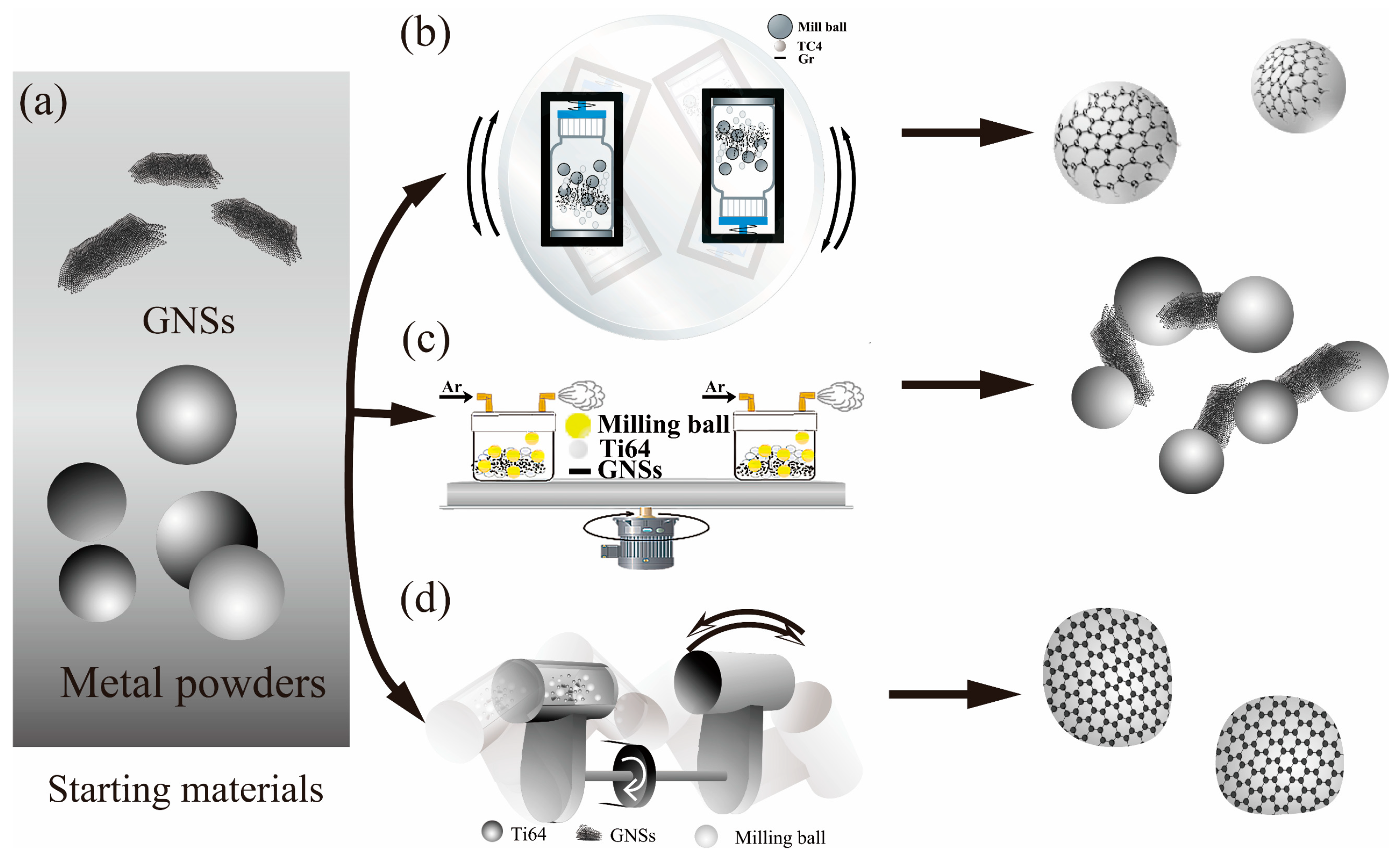
2.2. Dispersion Methods of the Composited Powders

Three powder dispersion methods, rocking milling (Figure 1b), planetary BM (Figure 1c,) and 3D BM (Figure 1d), were utilized to disperse the GNSs into metal powders with a ball to powder weight ratio of 1:1. Milling balls with a diameter of 10 mm were used in all processes. The schematic diagram and the illustration of powder shape are displayed in Figure 1.
A mechanical rocking mixer (NV-2F, Sanshin Trading Co., Ltd., Osaka, Japan) was used in rocking milling with low energy. Polycarbonate bottles (250 mL) were used as the mixing container, and the volume of powders and balls occupied 15–35% of the volume of the bottles. In this study, for example, 100 g GNSs/Ti64 powder and the same weight of ZrO2 milling balls were poured into a 250 mL polycarbonate bottle. Then the bottles were symmetrically loaded into the machine (Figure 1b) with a parameter of 60 Hz and milling time of 2 h.
In the planetary BM process, a planetary BM machine (Pulverisette 5, Fritsch, Rhineland-Palatinate, Germany) equipped with four symmetrical loading positions was utilized. A ZrO2 jar (500 mL) was used as the mixing container with the total volume of balls and powder less than 1/3 of the capacity of the jar. Here, for example, 400 g GNSs/Ti64 powder and ZrO2 milling balls were filled into the jars together. Before running, the jars were stuffed with argon and sealed (Figure 1c). Then the jars were symmetrically loaded into the positions, and milling was performed at 200 rpm for 4 h (running for 10 min and pausing for 20 min).
In 3D BM, a three-dimensional BM machine (SPEX 8000D, PYNN Co., Boston, MA, USA) was used. Eighty milliliter WC milling jars were used as the mixing containers with the total volume of powder and WC milling balls less than 25% of the capacity. Here, for example, 30 g of powder and milling balls were poured into the jars inside the glove box where they were filled with argon. Then, jars were sealed and loaded into the machine and run at 1450 rpm for 1 h (milling for 15 min and pausing for 15 min).

2.3. Morphology Characterization

The microstructure of the powders was observed by scanning electron microscope, SEM (TESCAN VEGA 3 LMU, Tescan Orsay Holding, Brno, Czech Republic), back electron microscope, BSE (Helios Nano-Lab G3 UC, Nanolab Technologies, Milpitas, CA, USA) and transmission electron microscopy, TEM (FEI Talos F200X, Thermo fisher scientific, Waltham, MA, USA) equipped with an energy dispersive spectrometer (EDS). HRTEM (high revolution TEM) and HAADF (high-angle annular dark field) were also obtained from the same instrument.
Microscopic confocal Raman spectroscopy (Alpha300R with 532 nm TEM00 laser, WITec, Ulm, Germany) was used to detect the structure and defects of GNSs at room temperature with a wavelength range of 0 to 3500 cm−1.

3. Results and Discussion

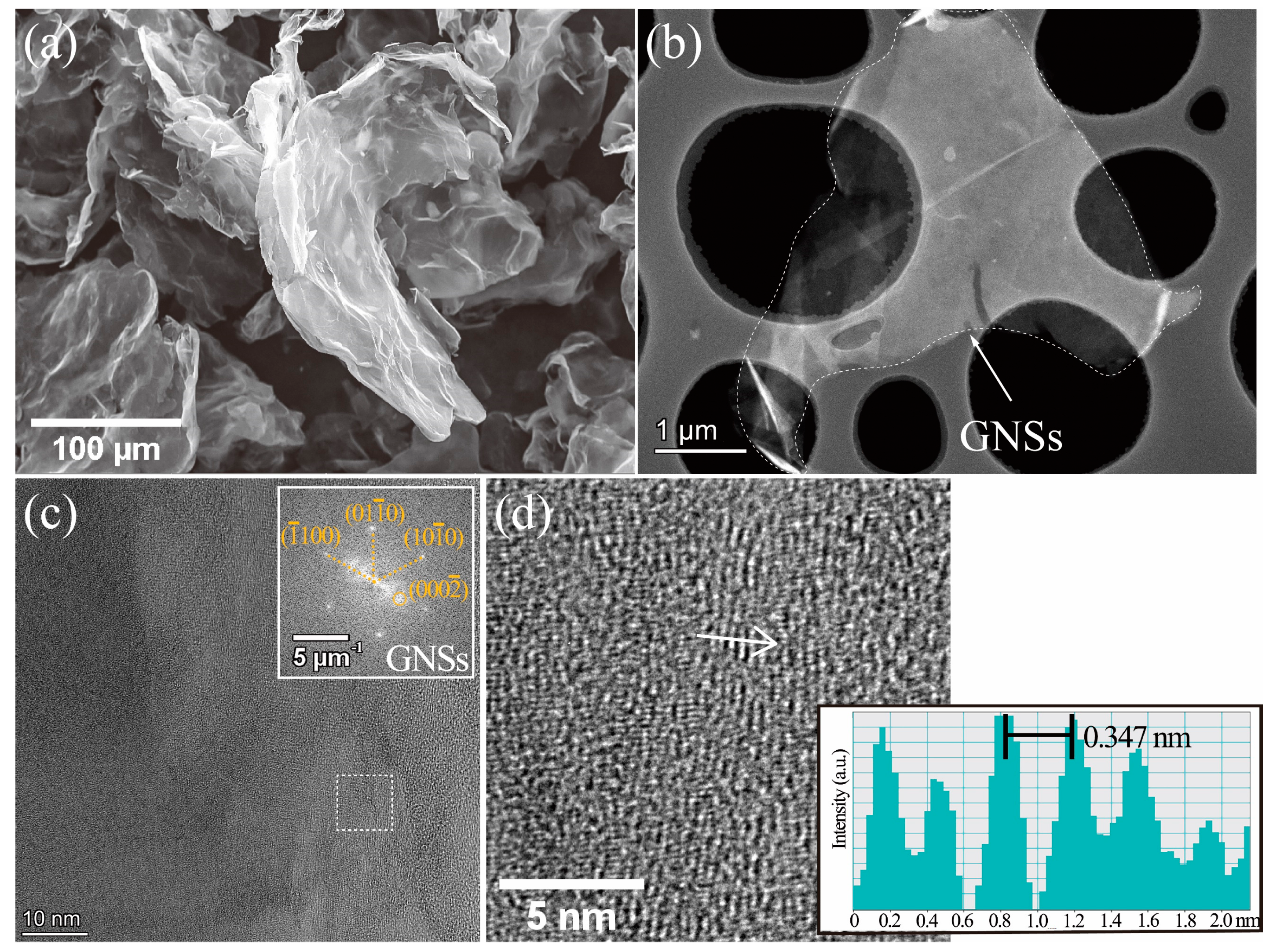
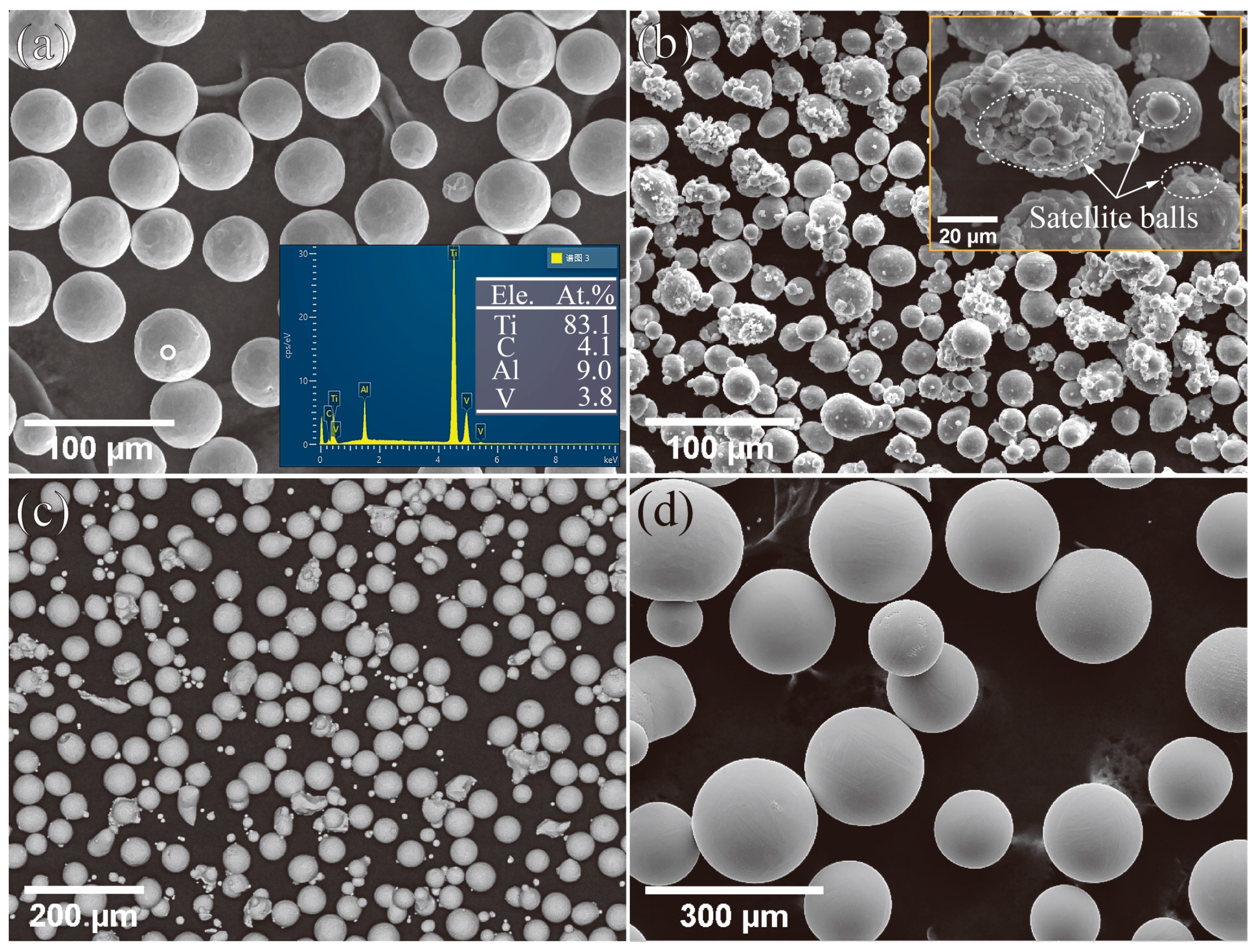
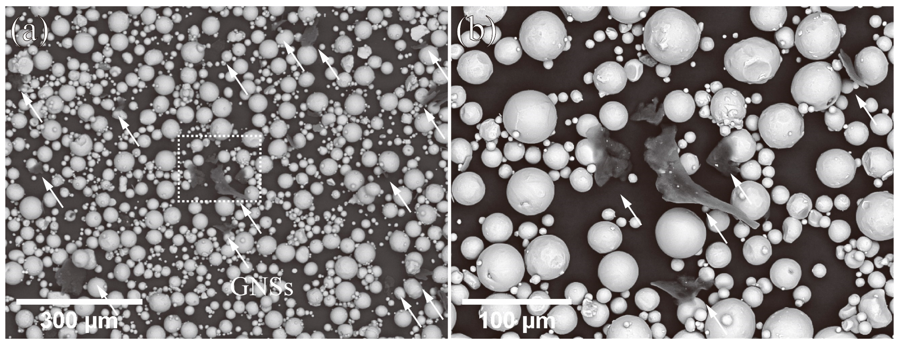
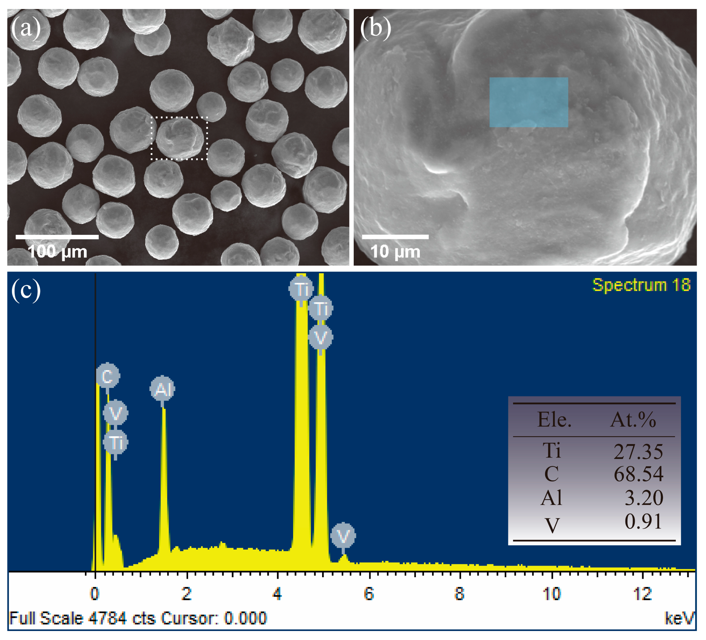
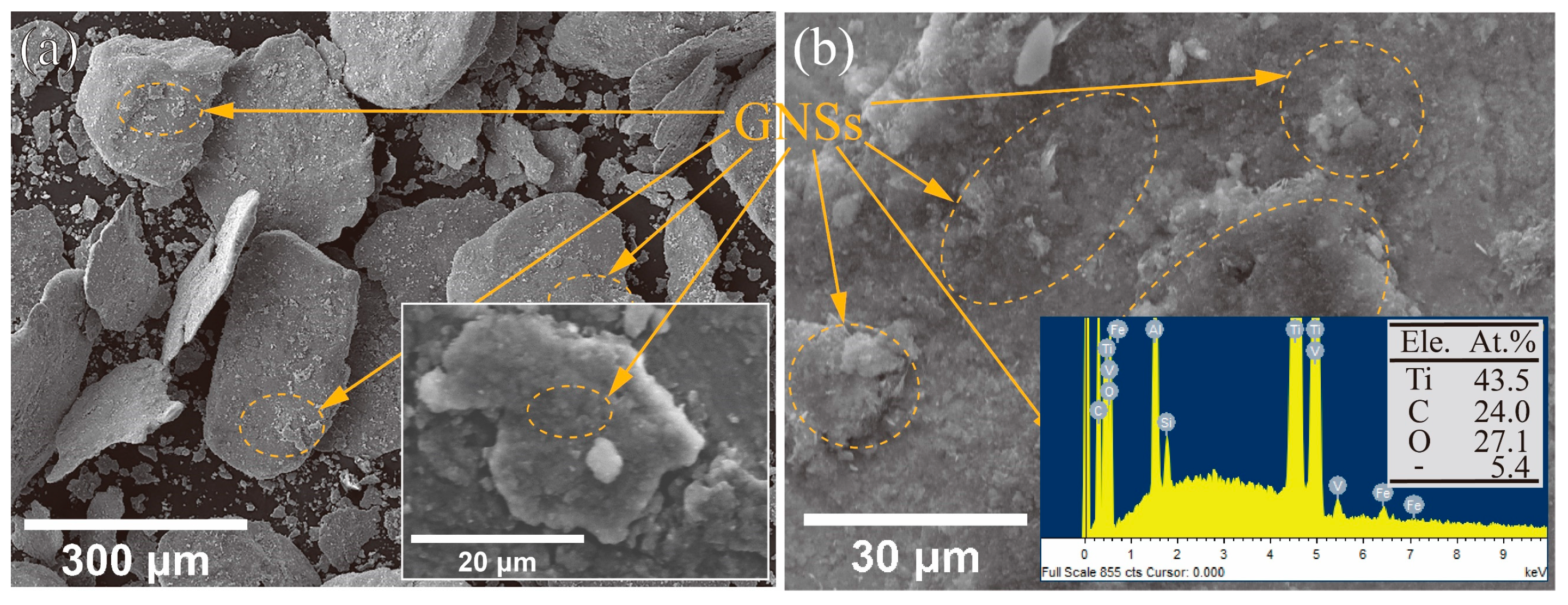
3.1. Raw Materials Characterization

Figure 2 shows the microstructure of raw GNSs powders. The SEM image displays the big bulk GNSs clustered together as multi-sheet layers with folds and small thin pieces. The HAADF image (Figure 2b) shows a piece of thin GNSs (~5 μm) with some folds appearing on the surface in bright contrast. The HRTEM image (Figure 2c) displays the lattice fringes of GNS, and the fast Fourier transform (the insert image in Figure 2c) illustrates the close-packed hexagonal structure of the GNS. In the white box in Figure 2c (magnified in Figure 2d), the lattice fringes can be observed clearly with a lattice space of 0.347 nm alongside the (0002) plane.
Figure 3 shows the morphology of the starting spherical metal powders. The #1 spherical Ti64 powders (Figure 3a) possessed an average diameter of 40 μm, and the relative EDS results on the powder surface suggest quite a low carbon content (<5%) for the accuracy error of instruments. The #1 Al powders (Figure 3b) had an average diameter of 45 μm with various irregular shapes. It appeared as a typical satellite ball structure where a number of small powder particles attached on the surface of bigger powders (insert image of Figure 3b), the larger particles being near-spherical structures. The SEM image of the #2 Ti64 powders with an average diameter of 55 μm is shown as Figure 3c. It can be observed that most powders were spherical shapes, while some were irregular structures. In addition, some fragmented powders with quite small sizes scattered among the larger powders. The #3 Ti64 powder (Figure 3d) with larger sized particles (an average diameter of 180 μm) exhibited better sphericity with few small satellite balls.

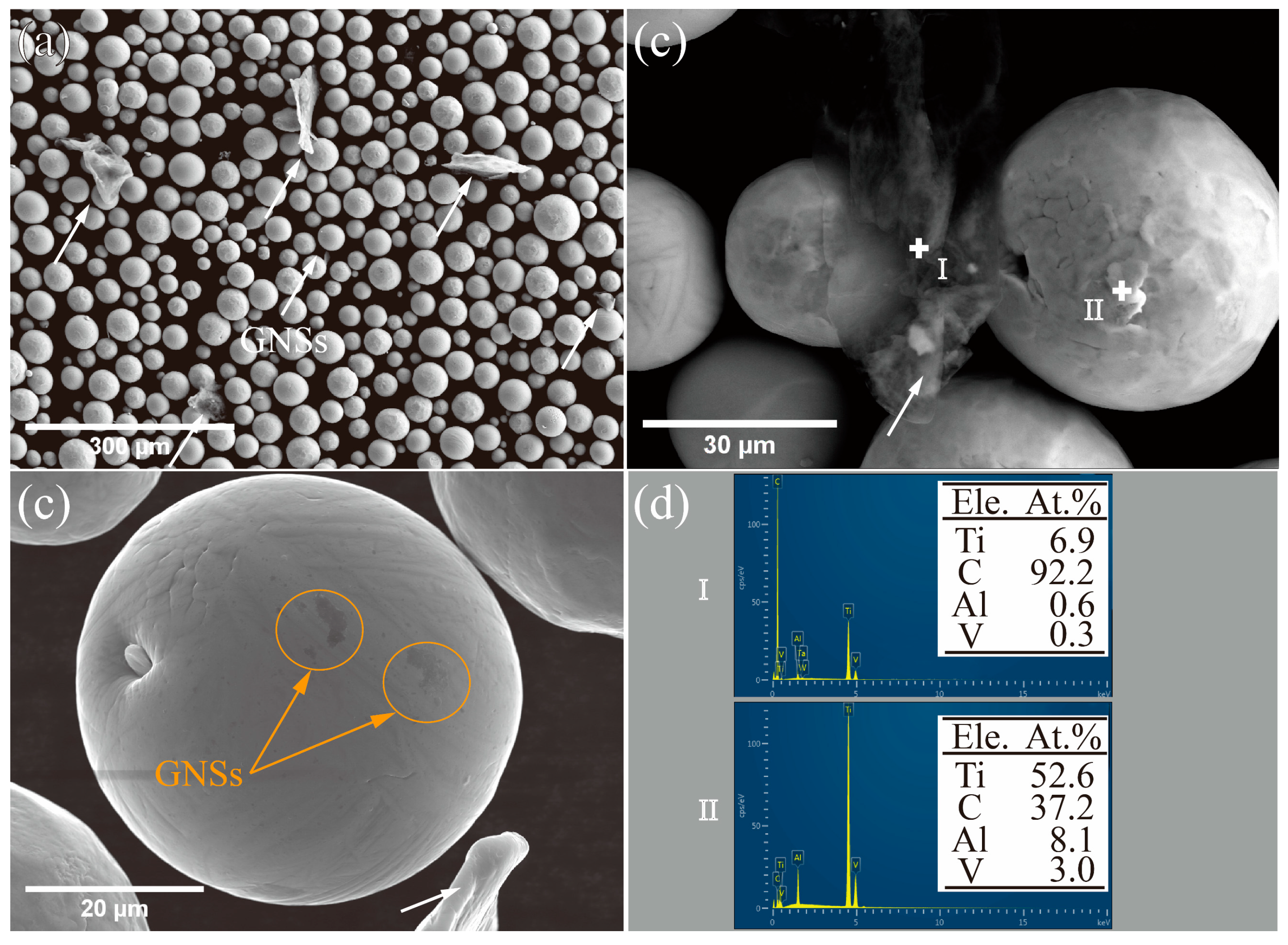
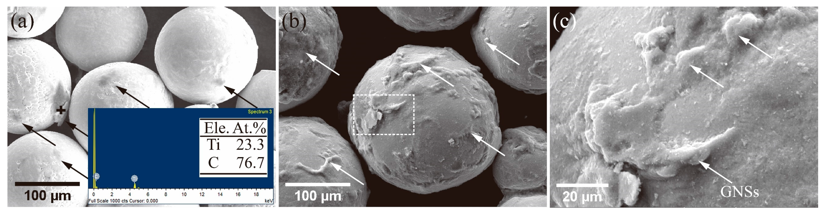
3.2. Powders after Low-Energy BM

Figure 4 shows the #1 GNSs/Ti64 composite powders fabricated by the rocking milling process. After dispersion (Figure 4a), single or clustered GNSs scattered randomly among the Ti64 powders (marked by arrows). It is obvious that the sizes of these drifting GNSs were larger than those Ti64 powders (Figure 4b). Even though, there were still a few GNSs attached on the surface of powders with big sizes (Figure 4c). The EDS spectra (Figure 4d) exhibited the increase in carbon content, which confirms the positions of GNSs among the powders and attached on the powder surface.
Figure 5 shows the BSE images of #2 GNSs/Ti64 composite powders with coarser Ti64 powder sizes. The different contrast of black and white (Figure 5a) manifests the different phases of GNSs (marked by arrows) and Ti64 in the composite powders. It was also observed that some single or clustered GNSs drifted among the basic Ti64 powders. When the selected box in Figure 5a is magnified (Figure 5b) , it can be seen that the drifting GNSs were slightly larger than those of the surrounding Ti64 powders. Furthermore, the drifting GNSs tended to distribute partially clustering, which is likely caused by the density discrepancy and strong Van der Waals forces between the drifting free GNSs.
When the GNSs were scattered among the Ti64 powders randomly via low-energy rocking mill methods, only a few GNSs with tiny sizes (Figure 4b) attached on the surface of Ti64 powders with much larger bulks. However, some GNSs (Figure 4a and Figure 5) with bigger diameters were still free to move among the spaces of composite powders. This will lead to secondary agglomeration triggered by the external force as the composite powders flow during the fabrication process, such as weighing and loading to the stamper. Therefore, for low-energy powder such as rocking milling, there is limited ability for a higher mass (more than 1 wt%) of GNSs to distribute uniformly in the metal powders. Even though the large discrepancy in particle sizes between GNSs and metal powders will lead to some small sized GNS attaching on the surface of large size powders, the increase in the powder diameters plays a limited role in low-energy BM dispersion of GNSs.

3.3. Composite Powders via HEBM

Figure 6a exhibits the SEM image of #1 GNSs/Ti64 powders after planetary BM. A few GNSs drifted among the powders, and the spherical powders were slightly deformed because of the BM collisions. The powder particle size was almost unchanged. When the box in Figure 6a is magnified (Figure 6b), the surface of the spherical powder becomes lightly coarse. The EDS results (Figure 6c) of the surface of the blue box exhibited the high mass content of carbon, which suggests that the GNSs were completely coated on the surface of powders without free GNSs drifting among the spaces of powder. This is likely due to the small difference in diameters between Ti64 powders and GNSs, where both metal powders and milling balls can cooperate together to break and mill the big bulks of GNSs into pieces. Thus, the tiny GNS fragments can attach on the surface of Ti64 powder.
Figure 7a displays the SEM image of #1 GNSs/Al after planetary BM. Comparing the shapes of the raw powders (Figure 3b), Al powders were notably deformed from a near-spherical shape into quite thin foils. These deformed foils maintained a similar size to the raw powder materials (Figure 7b). It suggests that the BM process will have a significant impact on the powder shape of low-hardness materials.
Due to the deformed nanoparticle foils, it is hard to distinguish the GNSs from the Al foils. Thus, Figure 8a exhibits a bright TEM image of deformed Al foils with uneven thickness and irregular shape. It is difficult to distinguish the GNSs from the Al matrix, while some single GNS can be found at the edges of powders (insert image of Figure 8a). The corresponding HAADF image (Figure 8b) illustrates that there is little discrepancy contrast inside the foils. However, according to the EDS maps of Al (Figure 8c) and C (Figure 8d), a big-size and thin-layer GNS is probably distributed uniformly on the surface or inside the Al foils without clustered GNSs. Therefore, the #1 Al powders probably had limited influence in the milling effects with GNSs.
In order to figure out the relationship between structural defects and diameters of powder, #3 GNSs/Ti64 composite powders with bigger diameters after BM are seen in Figure 9. Ti64 powders maintained a spherical shape after BM without free drifting GNSs (Figure 9a). The EDS spectra (insert image of Figure 9a) suggests the that bumps on the surface of powders with irregulate shapes and bulks were GNSs (marked by arrows, Figure 9b–c). This suggests that when the powder particle sizes increase, the milling effect with GNSs probably becomes weaker. Thus, large GNSs can remain on the surface of bigger-diameter powders with little breakage.
To understand the impacts of milling energy on the GNSs morphology, the #3 GNSs/Ti64 powders were also treated with a higher energy via 3D BM. Figure 10a shows that the #3 spherical Ti64 powders were notably deformed with irregular and flake shapes. GNSs (marked by arrows) with different particle size appeared clearly on the deformed surface (Figure 10b). This suggests even if the HEBM causes serious deformation of the powder, the GNSs are observed on the surface of powder under a lower magnification. In addition, the EDS spectra (insert image of Figure 10b) identified elements C, O, V, Al, Fe and Si on the surface of Ti64 powders (insert image of Figure 10a). The high content of carbon confirms GNSs attached on the powder surface. The oxygen peaks illustrate that HEBM will inevitably lead to the powder adsorbing the remaining oxygen during milling.

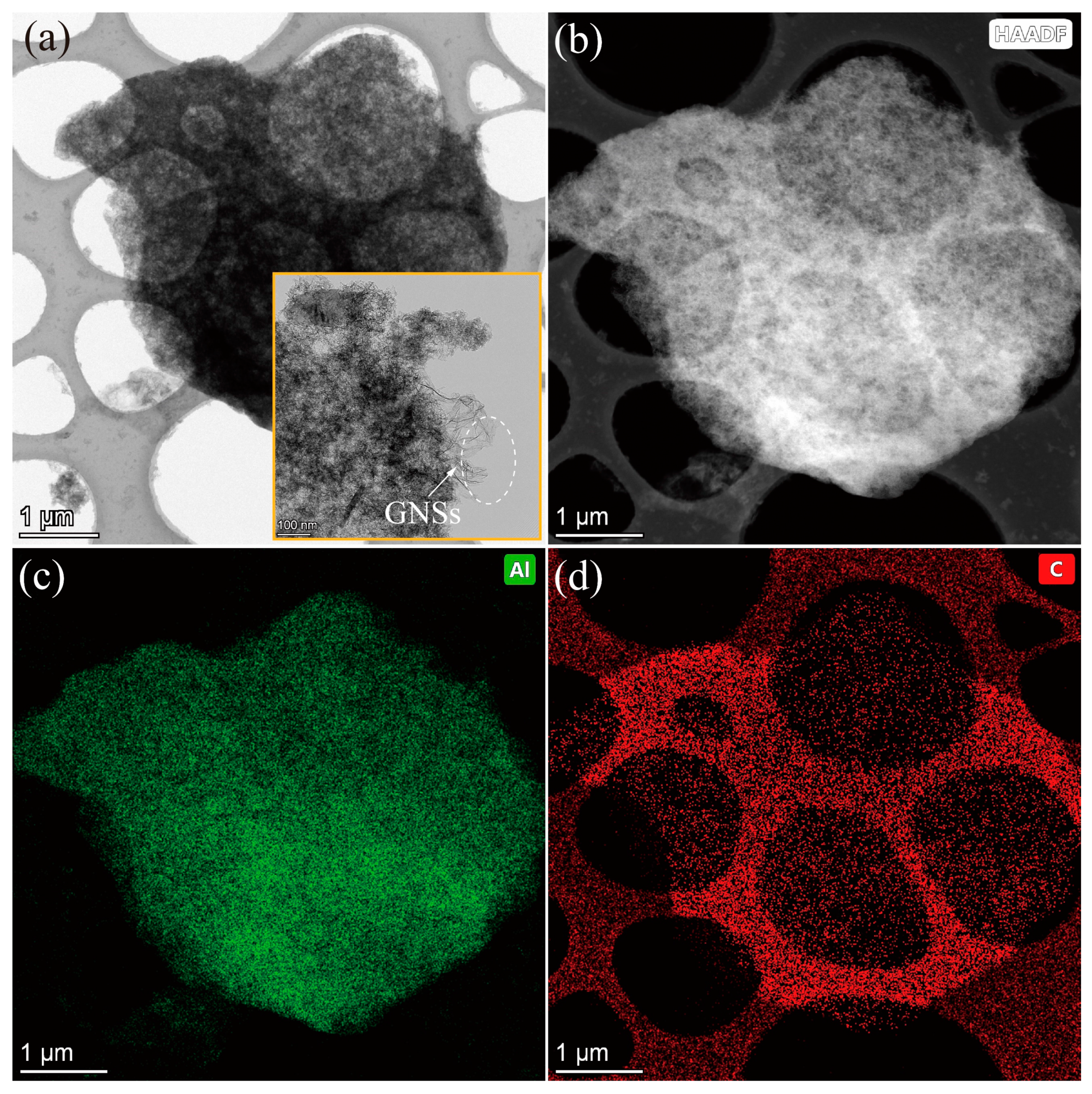
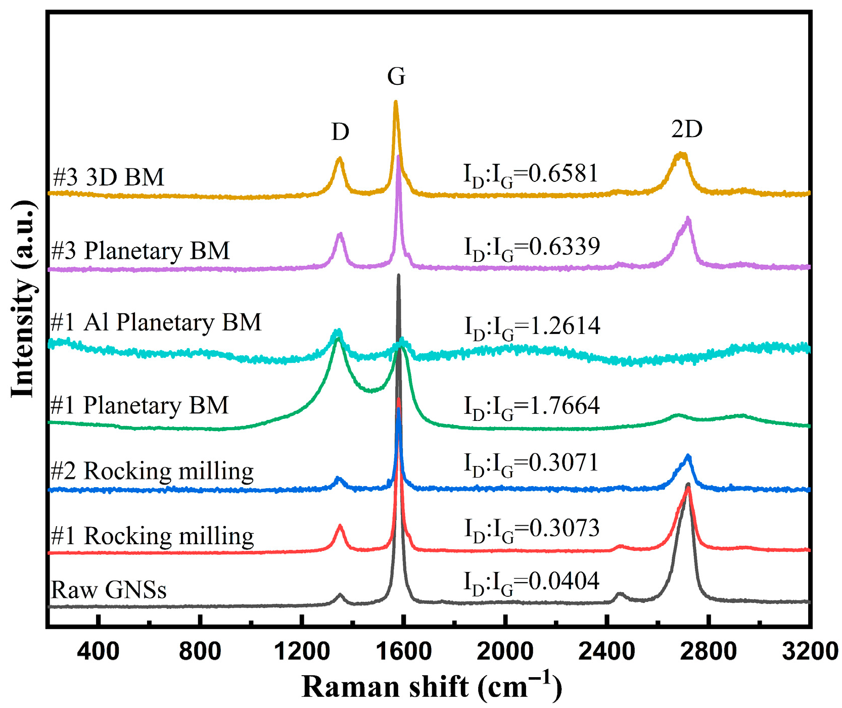
3.4. Structural Defects in Graphene Crystals

Although the diversification of deformed GNS microstructures can be clearly observed in the SEM and TEM images before and after BM, it is difficult to know if the structural defects in GNS crystals were caused by the dispersion process. Therefore, Raman spectra of the raw GNSs and all composite powders are presented (Figure 11) to measure the defects via the ratio of D- (defective structure, ~1349 cm−1) to G-bond (Graphene bond, ~1580 cm−1) [31,34,35]. The 2D bond (~2719 cm−1) contains information on the layer numbers according to its intensity and shape [36,37]. Moreover, the peak shifts (D-, G-, 2D-bond) caused by stress during BM [38,39] are listed in Table 1.
It suggests that the starting GNSs possessed a small value 0.0404 of ID/IG. Notwithstanding, the values increased 7–8-fold after rocking milling with similar peak shapes, which suggests that low-energy BM will introduce some structural defects to the GNSs with few layer numbers changing. Furthermore, the ratio values of #1 and #2 composite powder were similar (0.3071~0.3073), which implies that the diameters of powder had little impact on the structural defects to GNSs through low-energy BM such as rocking milling. By increasing the milling energy, such as with planetary BM, the peak shapes of small size #1 powders changed with much higher ID/IG values, 1.7664 (GNS/Ti64 powders) and 1.2614 (GNSs/Al powders), respectively. It suggests fine particle-size metal powders will introduce much more structural defects to GNSs with a better milling effect. Due to the hardness discrepancy of the powders between Al (0.5–1.3 GPa [40]) and Ti64 (3.5–5.3 GPa [41]), the softer Al powder will lead to less structural defects compared with the Ti64 composites powders. Moreover, the 2D-bond shifts at 2681 cm−1 (#1 GNSs/Ti64) and 2652 cm−1 (#1 GNSs/Al) with an inferior weak intensity imply the decreased layer numbers of GNSs for the damage. With increased diameter of Ti64 powders, the ratio value decreased to 0.6339 in #3 GNSs/Ti64 composite, around a 2–3-fold decrease compared to the #1 composite powders. This shows that the larger particle size of the metal powders used, the less structural defects will be introduced to GNSs. Moreover, the 2D peak shift (2717 cm−1) and shape were similar to the raw GNSs. Thus, it is probable that the layer numbers are constant without further deterioration. When the BM energy was high enough to force the Ti64 powders deformation (Figure 10), the Raman spectra of #3 GNSs/Ti64 powders via 3D BM showed that small structural defect increases may be caused by the ball collision. Compared to the #3 powder milled by planetary BM, the value ID/IG was 0.6581, a little higher than the 0.6339 value. This suggests that only a few more defects are introduced into GNSs even if the powders are seriously deformed, which confirms that the coarse powders will have a poor milling effect on the GNSs. Furthermore, the 2D peak position shifted slightly (2687.7 cm−1) with high intensity, which implies that the layer numbers may decrease slightly under the more serious ball collision. Thus, the larger particle sizes of powder will have much less milling effect on GNSs.

4. Conclusions

In this work, through applying three different powder metallurgy methods with different milling energy levels, GNSs were uniformly dispersed in metal powders with different damage states. Examinations of microstructures and structural defects were performed for the GNSs of composite powders with an emphasis on studying the increase in structural defects in GNS crystals caused by milling effects. According to the experimental results and discussion, it was concluded that the defects increased with higher BM energy. Conversely, a lower hardness of metal powders consumed the milling energy by deformation, which reduced the milling effect and inhibited the increase in structural defects in GNSs. Moreover, the increasing powder particle size helped lower the structural defects in GNS crystals. It was found that when the diameter of powder increased from around 15 μm to 300 μm, the ratio of ID/IG decreased 63%.

Author Contributions

Experiment, Formal analysis, data curation, writing—original draft preparation, writing—review and editing, Q.Y.; Methodology, Supervision, writing—review and editing, data curation, funding acquisition, B.C.; Experiment, investigation, X.Z.; Resources, supervision, project administration, J.L.; Resources, supervision, edition; K.K.; All authors have read and agreed to the published version of the manuscript.

Funding

This research was funded by the Key Research and Development Plan of Shaanxi Province, grant number 2020KW-034.

Institutional Review Board Statement

Not applicable.

Informed Consent Statement

Not applicable.

Data Availability Statement

No new data were created or analyzed in this study. Data sharing is not applicable to this article.

Acknowledgments

The authors would like to thank the financial support from the Key Research and Development Plan of Shaanxi Province (2020KW-034).

Conflicts of Interest

The authors declare no conflict of interest.

References

  1. Soltani, N.; Jafari Nodooshan, H.R.; Bahrami, A.; Pech-Canul, M.I.; Liu, W.; Wu, G. Effect of hot extrusion on wear properties of Al-15wt.% Mg2Si in situ metal matrix composites. Mater. Des. 2014, 53, 774–781. [Google Scholar] [CrossRef]
  2. Soltani, N.; Sadrnezhaad, S.K.; Bahrami, A. Manufacturing wear-resistant 10Ce-TZP/Al2O3 nanoparticle aluminum composite by powder metallurgy processing. Mater. Manuf. Pro. 2014, 29, 1237–1244. [Google Scholar] [CrossRef]
  3. Xin, L.; Yang, W.; Zhao, Q.; Dong, R.; Wu, P.; Xiu, Z.; Hussain, M.; Wu, G. Strengthening behavior in SiC nanowires reinforced pure Al composite. J. Alloys Compd. 2017, 695, 2406–2412. [Google Scholar] [CrossRef]
  4. Liu, B.X.; Huang, L.J.; Kaveendran, B.; Geng, L.; Cui, X.P.; Wei, S.L.; Yin, F.X. Tensile and bending behaviors and characteristics of laminated Ti-(TiBw/Ti) composites with different interface status. Compos. Part B 2017, 108, 377–385. [Google Scholar] [CrossRef]
  5. Wei, W.H.; Zhang, Q.; Wu, W.J.; Cao, H.Z.; Shen, J.; Fan, S.Q.; Duan, X.M. Agglomeration-free nanoscale TiC reinforced titanium matrix composites achieved by in-situ laser additive manufacturing. Scripta Materialia 2020, 187, 310–316. [Google Scholar] [CrossRef]
  6. Adebisi, A.A.; Maleque, M.A.; Rahman, M.M. Metal matrix composite brake rotor: Historical development and product life cycle analysis. Int. J. Automot. Mech. Eng. 2011, 4, 974–980. [Google Scholar] [CrossRef]
  7. Quast, J.P.; Boehlert, C.J. The out-of-phase thermomechanical fatigue behavior of Ultra SCS-6/Ti-24Al-17Nb-xMo (at.%) metal matrix composites. Int. J. Fatigue 2010, 32, 610–620. [Google Scholar] [CrossRef]
  8. Tjong, S.C. Recent progress in the development and properties of novel metal matrix nanocomposites reinforced with carbon nanotubes and graphene nanosheets. Mater. Sci. Eng. R 2013, 74, 281–350. [Google Scholar] [CrossRef]
  9. Hu, Z.; Tong, G.; Lin, D.; Chen, C.; Guo, H.; Xu, J.; Zhou, L. Graphene-reinforced metal matrix nanocomposites—A review. Mater. Sci. Technol. 2016, 32, 930–953. [Google Scholar] [CrossRef]
  10. Huang, L.J.; Geng, L.; Peng, H.X. Microstructurally inhomogeneous composites: Is a homogeneous reinforcement distribution optimal? Prog. Mater. Sci. 2015, 71, 93–168. [Google Scholar] [CrossRef]
  11. Yan, Q.; Chen, B.; Li, J.S. A review of carbon nanomaterials reinforced titanium metal matrix composites. Mater. China 2019, 38, 1061–1073. [Google Scholar]
  12. Gu, D.; Rao, X.; Dai, D.; Ma, C.; Xi, L.; Lin, K. Laser additive manufacturing of carbon nanotubes (CNTs) reinforced aluminum matrix nanocomposites: Processing optimization, microstructure evolution and mechanical properties. Add. Manuf. 2019, 29. [Google Scholar] [CrossRef]
  13. Munir, K.S.; Kingshott, P.; Wen, C. Carbon nanotube reinforced titanium metal matrix composites prepared by powder metallurgy—A review. Cri. Rev. Solid State Mater. Sci. 2015, 40, 38–55. [Google Scholar] [CrossRef]
  14. Munir, K.S.; Li, Y.; Liang, D.; Qian, M.; Xu, W.; Wen, C. Effect of dispersion method on the deterioration, interfacial interactions and re-agglomeration of carbon nanotubes in titanium metal matrix composites. Mater. Des. 2015, 88, 138–148. [Google Scholar] [CrossRef]
  15. Chen, B.; Li, S.; Imai, H.; Jia, L.; Umeda, J.; Takahashi, M.; Kondoh, K. An approach for homogeneous carbon nanotube dispersion in Al matrix composites. Mater. Des. 2015, 72, 1–8. [Google Scholar] [CrossRef]
  16. Hwang, J.; Yoon, T.; Jin, S.H.; Lee, J.; Kim, T.S.; Hong, S.H.; Jeon, S. Enhanced mechanical properties of graphene/copper nanocomposites using a molecular-level mixing process. Adv. Mater. 2013, 25, 6724–6729. [Google Scholar] [CrossRef]
  17. Zhang, X.; Shi, C.; Liu, E.; He, F.; Ma, L.; Li, Q.; Li, J.; Zhao, N.; He, C. In-situ space-confined synthesis of well-dispersed three-dimensional graphene/carbon nanotube hybrid reinforced copper nanocomposites with balanced strength and ductility. Compos. Part A 2017, 103, 178–187. [Google Scholar] [CrossRef]
  18. Zhang, X.; Xu, Y.; Wang, M.; Liu, E.; Zhao, N.; Shi, C.; Lin, D.; Zhu, F.; He, C. A powder-metallurgy-based strategy toward three-dimensional graphene-like network for reinforcing copper matrix composites. Nat. Commun. 2020, 11, 2775. [Google Scholar] [CrossRef]
  19. Deaquino-Lara, R.; Soltani, N.; Bahrami, A.; Gutiérrez-Castañeda, E.; García-Sánchez, E.; Hernandez-Rodríguez, M.A.L. Tribological characterization of Al7075–graphite composites fabricated by mechanical alloying and hot extrusion. Mater. Des. 2015, 67, 224–231. [Google Scholar] [CrossRef]
  20. Liu, G.; Zhao, N.; Shi, C.; Liu, E.; He, F.; Ma, L.; Li, Q.; Li, J.; He, C. In-situ synthesis of graphene decorated with nickel nanoparticles for fabricating reinforced 6061Al matrix composites. Mater. Sci. Eng. A 2017, 699, 185–193. [Google Scholar] [CrossRef]
  21. Guo, B.; Song, M.; Yi, J.; Ni, S.; Shen, T.; Du, Y. Improving the mechanical properties of carbon nanotubes reinforced pure aluminum matrix composites by achieving non-equilibrium interface. Mater. Des. 2017, 120, 56–65. [Google Scholar] [CrossRef]
  22. Zhou, H.; Zhang, C.; Han, B.; Qiu, J.; Qin, S.; Gao, K.; Liu, J.; Sun, S.; Zhang, H. Microstructures and mechanical properties of nanocrystalline AZ31 magnesium alloy powders with submicron TiB2 additions prepared by mechanical milling. Crystals 2020, 10, 550. [Google Scholar] [CrossRef]
  23. Matli, P.R.; Sheng, J.G.; Parande, G.; Manakari, V.; Chua, B.W.; Wong, S.C.; Gupta, M. A novel method of light weighting aluminium using magnesium syntactic composite core. Crystals 2020, 10, 917. [Google Scholar] [CrossRef]
  24. Shimizu, Y.; Miki, S.; Soga, T.; Itoh, I.; Todoroki, H.; Hosono, T.; Sakaki, K.; Hayashi, T.; Kim, Y.A.; Endo, M.; et al. Multi-walled carbon nanotube-reinforced magnesium alloy composites. Scr. Mater. 2008, 58, 267–270. [Google Scholar] [CrossRef] [Green Version]
  25. Chu, K.; Wang, F.; Li, Y.-b.; Wang, X.-h.; Huang, D.-j.; Zhang, H. Interface structure and strengthening behavior of graphene/CuCr composites. Carbon 2018, 133, 127–139. [Google Scholar] [CrossRef]
  26. Kim, W.J.; Lee, T.J.; Han, S.H. Multi-layer graphene/copper composites: Preparation using high-ratio differential speed rolling, microstructure and mechanical properties. Carbon 2014, 69, 55–65. [Google Scholar] [CrossRef]
  27. Wang, F.-C.; Zhang, Z.-H.; Sun, Y.-J.; Liu, Y.; Hu, Z.-Y.; Wang, H.; Korznikov, A.V.; Korznikova, E.; Liu, Z.-F.; Osamu, S. Rapid and low temperature spark plasma sintering synthesis of novel carbon nanotube reinforced titanium matrix composites. Carbon 2015, 95, 396–407. [Google Scholar] [CrossRef]
  28. Mu, X.N.; Cai, H.N.; Zhang, H.M.; Fan, Q.B.; Wang, F.C.; Zhang, Z.H.; Ge, Y.X.; Shi, R.; Wu, Y.; Wang, Z.; et al. Uniform dispersion and interface analysis of nickel coated graphene nanoflakes/ pure titanium matrix composites. Carbon 2018, 137, 146–155. [Google Scholar] [CrossRef]
  29. Dong, L.L.; Lu, J.W.; Fu, Y.Q.; Huo, W.T.; Liu, Y.; Li, D.D.; Zhang, Y.S. Carbonaceous nanomaterial reinforced Ti-6Al-4V matrix composites: Properties, interfacial structures and strengthening mechanisms. Carbon 2020, 164, 272–286. [Google Scholar] [CrossRef]
  30. Munir, K.S.; Zheng, Y.; Zhang, D.; Lin, J.; Li, Y.; Wen, C. Microstructure and mechanical properties of carbon nanotubes reinforced titanium matrix composites fabricated via spark plasma sintering. Mater. Sci. Eng. A 2017, 688, 505–523. [Google Scholar] [CrossRef]
  31. Chen, B.; Shen, J.; Ye, X.; Jia, L.; Li, S.; Umeda, J.; Takahashi, M.; Kondoh, K. Length effect of carbon nanotubes on the strengthening mechanisms in metal matrix composites. Acta Mater. 2017, 140, 317–325. [Google Scholar] [CrossRef]
  32. Munir, K.S.; Zheng, Y.; Zhang, D.; Lin, J.; Li, Y.; Wen, C. Improving the strengthening efficiency of carbon nanotubes in titanium metal matrix composites. Mater. Sci. Eng. A 2017, 696, 10–25. [Google Scholar] [CrossRef]
  33. Munir, K.S.; Oldfield, D.T.; Wen, C. Role of process control agent in the synthesis of multi-walled carbon nanotubes reinforced titanium metal matrix powder mixtures. Adv. Eng. Mater. 2016, 18, 294–303. [Google Scholar] [CrossRef]
  34. Yan, Q.; Chen, B.; Li, J.S. Super-high-strength graphene/titanium composites fabricated by selective laser melting. Carbon 2021, 174, 451–462. [Google Scholar] [CrossRef]
  35. Mu, X.N.; Cai, H.N.; Zhang, H.M.; Fan, Q.B.; Wang, F.C.; Zhang, Z.H.; Wu, Y.; Ge, Y.X.; Chang, S.; Shi, R.; et al. Uniform dispersion of multi-layer graphene reinforced pure titanium matrix composites via flake powder metallurgy. Mater. Sci. Eng. A 2018, 725, 541–548. [Google Scholar] [CrossRef]
  36. Ferrari, A.C.; Meyer, J.C.; Scardaci, V.; Casiraghi, C.; Lazzeri, M.; Mauri, F.; Piscanec, S.; Jiang, D.; Novoselov, K.S.; Roth, S.; et al. Raman spectrum of graphene and graphene layers. Phys. Rev. Lett. 2006, 97. [Google Scholar] [CrossRef] [Green Version]
  37. Ribeiro-Soares, J.; Oliveros, M.E.; Garin, C.; David, M.V.; Martins, L.G.P.; Almeida, C.A.; Martins-Ferreira, E.H.; Takai, K.; Enoki, T.; Magalhães-Paniago, R.; et al. Structural analysis of polycrystalline graphene systems by Raman spectroscopy. Carbon 2015, 95, 646–652. [Google Scholar] [CrossRef] [Green Version]
  38. Chen, B.; Shen, J.; Ye, X.; Imai, H.; Umeda, J.; Takahashi, M.; Kondoh, K. Solid-state interfacial reaction and load transfer efficiency in carbon nanotubes (CNTs)-reinforced aluminum matrix composites. Carbon 2017, 114, 198–208. [Google Scholar] [CrossRef]
  39. Pavithra, C.L.; Sarada, B.V.; Rajulapati, K.V.; Rao, T.N.; Sundararajan, G. A new electrochemical approach for the synthesis of copper-graphene nanocomposite foils with high hardness. Sci Rep. 2014, 4, 4049. [Google Scholar] [CrossRef] [PubMed]
  40. Chen, B.; Moon, S.K.; Yao, X.; Bi, G.; Shen, J.; Umeda, J.; Kondoh, K. Comparison study on additive manufacturing (AM) and powder metallurgy (PM) AlSi10Mg alloys. JOM 2018, 70, 644–649. [Google Scholar] [CrossRef]
  41. Yan, Q.; Chen, B.; Kang, N.; Lin, X.; Lv, S.; Kondoh, K.; Li, S.; Li, J.S. Comparison study on microstructure and mechanical properties of Ti-6Al-4V alloys fabricated by powder-based selective-laser-melting and sintering methods. Mater. Charact. 2020, 164, 110358. [Google Scholar] [CrossRef]
Figure 1. Schematic diagram of the fabrication of composite powders: starting materials (a); rocking milling (b); planetary BM (c); 3D BM (d).
Crystals 11 00260 g001
Figure 2. SEM image (a), HAADF-TEM image (b), HRTEM image (c), and magnified HRTEM with (d) lattice fringe of GNSs.
Crystals 11 00260 g002
Figure 3. SEM image of #1 Ti64 powders (a), #1 Al powders (b), #2 Ti64 powders (c), and #3 Ti64 powders (d).
Crystals 11 00260 g003
Figure 4. SEM images of #1 GNSs/Ti64 composite powders via rocking milling (a), GNSs among powders (b), GNSs on the surface (c), and EDS spectra (d).
Crystals 11 00260 g004
Figure 5. BSE images of #2 GNS/Ti64 composite powders via rocking milling (a) and the magnified box (b).
Crystals 11 00260 g005
Figure 6. SEM images of #1 GNSs/Ti64 composite via powders planetary BM (a), the magnified box (b), and the EDS spectra (c).
Crystals 11 00260 g006
Figure 7. SEM image of #1 GNSs/Al composite powders (a) and magnified SEM image (b).
Crystals 11 00260 g007
Figure 8. TEM image of GNS/Al composite powders: bright TEM image (a); HAADF image (b). EDS maps of Al (c) and C (d).
Crystals 11 00260 g008
Figure 9. SEM images of #3 GNS/Ti64 composite powders by planetary BM (a,b) and the magnified box (c).
Crystals 11 00260 g009
Figure 10. SEM images of #3 GNS/Ti64 composite powders (a) via three-dimensional BM and a magnified powder surface (b).
Crystals 11 00260 g010
Figure 11. Raman spectra of GNSs and GNSs/metal composite powders.
Crystals 11 00260 g011
Table 1. GNS peak position obtained from Raman spectra.
PowdersD/cm−1G/cm−12D/cm−1
Raw GNSs1349.61580.52719.2
#1 Rocking milling1349.61580.52719.2
#2 Rocking milling1349.11579.92719.6
#1 Planetary BM1344.11592.12681.5
#1 Al Planetary BM1343.71594.42652.6
#3 Planetary BM1349.815802717
#3 3D BM1349.51569.32687.7
Publisher’s Note: MDPI stays neutral with regard to jurisdictional claims in published maps and institutional affiliations.

