Article

1,4-Dibromo-2,5-bis(phenylalkoxy)benzene Derivatives: C–Br...π(arene) Versus C–H...Br and Br...Br Interactions in the Solid State

by
Giacomo Manfroni
,
Alessandro Prescimone
,
Edwin C. Constable
and
Catherine E. Housecroft
*
Department of Chemistry, University of Basel, BPR 1096, Mattenstrasse 24a, CH-4058 Basel, Switzerland
*
Author to whom correspondence should be addressed.
Submission received: 10 March 2021 / Revised: 21 March 2021 / Accepted: 23 March 2021 / Published: 25 March 2021
(This article belongs to the Special Issue Advanced Research in Halogen Bonding)

Abstract

:
We have prepared and characterized 1,4-dibromo-2,5-bis(2-phenylethoxy)benzene (1) and 1,4-dibromo-2,5-bis(3-phenylpropoxy)benzene (2). Their single-crystal structures confirm that, at the molecular level, they are similar with the phenylalkoxy chains in extended conformations. However, there are significant differences in packing interactions. The packing in 1 is dominated by C–Br...π(arene) interactions, with each Br located over one C–C bond of the central arene ring of an adjacent molecule. In contrast, the packing of molecules of 2 involves a combination of C–H...Br hydrogen bonds, Br...Br interactions, and arene–arene π-stacking. The single-crystal structures of both orthorhombic and triclinic polymorphs of 1 have been determined and the packing interactions are shown to be essentially identical.

Graphical Abstract

1. Introduction

In 2013, the IUPAC provided the following definition of a halogen bond [1]: “A halogen bond occurs when there is evidence of a net attractive interaction between an electrophilic region associated with a halogen atom in a molecular entity and a nucleophilic region in another, or the same, molecular entity”. Despite this definition, the nature of the halogen bond and the scope of close contacts that fall under this umbrella remain a subject of debate, and the IUPAC definition has been termed “elusive” in a recent review by Meyer and coworkers [2]. The relatively recent recognition of halogen bonding as an important supramolecular interaction in crystal engineering has spawned numerous reviews and data-mining overviews in the past few years [3,4,5,6,7,8,9,10]. Of particular note are discussions which demonstrate the distinction between a halogen bond and a halogen...halogen interaction [11,12]. When a halogen atom X forms a covalent bond, e.g., a C–X bond, the resulting electron distribution is such that atom X possesses an ‘electrophilic cap’ (also referred to as a ‘σ-hole’) located zenithal to the C–X covalent bond. This electron-poor region complements the electron-rich ‘belt’ around atom X, allowing X to act as either an electron acceptor or donor, respectively. The ‘halogen bond’ encompasses interactions in which the covalently bound halogen atom acts as an electrophile towards a heteroatom such as N, O, or S. In addition to halogen bonds, solid-state structures may exhibit close (≤the sum of the van der Waals radii) contacts between halogen atoms. Such interactions typically involve Cl, Br and I atoms and may be classified as type I or type II interactions as depicted in Scheme 1 [13]. Interactions are not confined to homonuclear interactions, although analysis of entries in the Cambridge Structural Database (CSD) reveal that Cl...Cl and Br...Br are the most common halogen...halogen contacts [11,13]. Analyses of scatter plots of angles θ1 against θ2 (defined in Scheme 1) by Desiraju and coworkers have illustrated that there is a clear distinction between type I and II interactions for I...I contacts. However, this becomes less well defined for Br...Br contacts, and even less so for Cl...Cl contacts [13]. Spilfogel et al. have similarly analysed plots of θ1 against θ2, and (with a restricted set of halogenated porphyrins) also demonstrated the difficulties in unambiguously assigning the structure type [11].
As well as encompassing hydrogen bonds, halogen bonds and halogen...halogen short contacts, supramolecular interactions involving halogen atoms also include halogen...π contacts. The role of C–I...π interactions in molecular crystals has recently been surveyed in detail by Tiekink [14]. The criteria used to define a ‘delocalized C–I...π(arene)’ contact were that the angle α (defined in Scheme 2a) was between 160° and 180°, and that the ring-centroid....I separation was ≤3.88 Å. This limit derives from the van der Waals radius of I (1.98 Å [15]) and half of the upper limit of an arene...arene π-stacking distance (half of ≈ 3.8 Å [16]). In addition to this ‘delocalized’ C–X...π(arene) interaction (X = any halogen), classifications of ‘localized’ and ‘semi-localized’ contacts have been introduced which place an emphasis on C...X separations (Scheme 2b) [17,18] rather than ring-centroid...X. The semi-localized and localized, rather than delocalized, interactions dominate in crystal packing. Significantly, C–X...π(arene) interactions with X = F are as numerous as those with X = Cl, Br and I [19,20].
Given the current interest in the diversity of supramolecular interactions involving halogen atoms, both in the solid state (see above) and in solution [21], we were encouraged to present the structural differences found in the single-crystal structures of 1,4-dibromo-2,5-bis(2-phenylethoxy)benzene (1) and 1,4-dibromo-2,5-bis(3-phenylpropoxy)benzene (2).

2. Materials and Methods

2.1. General

1H and 13C{1H} NMR spectra were recorded on a Bruker Avance III-500 spectrometer (Bruker BioSpin AG, Fällanden, Switzerland) at 298 K. The 1H and 13C NMR chemical shifts were referenced with respect to residual solvent peaks (δ TMS = 0). Electrospray ionization (ESI) mass spectra with ion separation using time of flight (TOF) were measured on a Bruker maXis 4G QTOF instrument (Bruker BioSpin AG, Fällanden, Switzerland). PerkinElmer UATR Two (Perkin Elmer, 8603 Schwerzenbach, Switzerland) and UV-2600 (Shimadzu Schweiz GmbH, 4153 Reinach, Switzerland) spectrometers were used to record solid-state FT-infrared (IR) and solution absorption spectra, respectively.
(2-bromoethyl)benzene and 2,5-dibromobenzene-1,4-diol were bought from Alfa Aesar (Thermo Fisher GmbH, 76870 Kandel, Germany) and Sigma Aldrich (Merck, 9470 Buchs, Switzerland), repectively, and 1-bromo-3-phenylpropane was bought from Fluka (Fluka Chemie GmbH, 9471 Buchs, Switzerland). All chemicals were used as received.

2.2. 1,4-Dibromo-2,5-bis(2-phenylethoxy)benzene, 1

Dry DMF (40 mL) was added to a mixture of anhydrous K2CO3 (3.61 g, 26.1 mmol), 2,5-dibromobenzene-1,4-diol (2.00 g, 7.47 mmol) and (2-bromoethyl)benzene (3.66 mL, 26.1 mmol). The solution was stirred and heated to 100 °C under a nitrogen atmosphere for 22 h. The mixture was cooled to room temperature, poured onto ice water (200 mL) and stirred for 20 min. The resulting suspension was extracted with CHCl3 (3 × 100 mL), dried with MgSO4 and concentrated in vacuo. The red-brown solid was recrystallized from a hot mixture of MeOH and CHCl3 (cooled down to room temperature). The filtrate was reduced to half its original volume, and then cooled to 5 °C to yield a second crop of crystalline product. Off-white crystals were isolated by filtration, washed with MeOH and then dried in vacuo for 2 days (2.55 g, 5.36 mmol, 71.7%). M.p. = 126.5–127.0 °C. 1H NMR (500 MHz, DMSO-d6) δ/ppm 7.34 (overlapping m + s, 6H, HB2+A3), 7.30 (t, J = 7.6 Hz, 4H, HB3), 7.21 (t, J = 7.2, 2H, HB4), 4.21 (t, J = 6.7 Hz, 4H, Ha), 3.02 (t, J = 6.7 Hz, 4H, Hb). 13C{1H} NMR (500 MHz, DMSO-d6) δ/ppm 149.3 (CA2), 138.1 (CB1), 129.1 (CB2), 128.2 (CB3), 126.3 (CB4), 118.1 (CA3), 110.4 (CA1), 70.2 (Ca), 34.9 (Cb). UV-VIS (MeCN, 2.0 × 10⁻⁵ mol dm−3) λ/nm 210 (ε/dm3 mol−1 cm−1 48,300), 232 sh (14,300), 300 (5760). HR-ESI MS m/z 498.9699 [M + Na]+ (calc. 498.9702). Found C 55.09, H 4.01; required: C 55.49, H 4.23.

2.3. 1,4-Dibromo-2,5-bis(3-phenylpropoxy)benzene, 2

Dry DMF (40 mL) was added to a mixture of anhydrous K2CO3 (3.61 g, 26.1 mmol), 2,5-dibromobenzene-1,4-diol (2.00 g, 7.47 mmol) and (3-bromopropyl)benzene (3.97 mL, 26.1 mmol). The yellow-brown suspension was stirred and heated to 100 °C under a nitrogen atmosphere for 22 h. The pale yellow mixture was cooled to room temperature, poured onto ice water (200 mL), and stirred for 20 min. The resulting suspension was extracted with CH2Cl2 (3 × 100 mL), dried with MgSO4 and concentrated in vacuo. The ochre solid was recrystallized from a hot mixture of MeOH and CHCl3 which was cooled down to room temperature. Colorless crystals were isolated by filtration, washed with MeOH, and then dried in vacuo overnight (3.29 g, 6.52 mmol, 87.3%). M.p. = 86.4–87.8 °C. 1H NMR (500 MHz, DMSO-d6) δ/ppm 7.34 (s, 2H, HA3), 7.29 (t, J = 7.4 Hz, 4H, HB3), 7.22 (d, J = 6.7 Hz, 4H, HB2), 7.18 (t, J = 7.2 Hz, 2H, HB4), 4.00 (t, J = 6.2 Hz, 4H, Ha), 2.77 (t, J = 7.6 Hz, 4H, Hc), 1.99 (m, 4H, Hb). 13C{1H} NMR (500 MHz, DMSO-d6) δ/ppm 149.4 (CA2), 141.2 (CB1), 128.4 (CB2/CB3), 128.3 (CB2/CB3), 125.9 (CB4), 118.3 (CA3), 110.6 (CA1), 68.7 (Ca), 31.3 (Cc), 30.3 (Cb). UV-VIS (MeCN, 2.0 × 10⁻⁵ mol dm−3) λ/nm 210 (ε/dm3 mol−1 cm−1 52,000), 232 sh (13,700), 302 (5510). HR-ESI MS m/z 527.0017 [M + Na]+ (calc. 527.0015). Found C 57.27, H 4.68; required: C 57.17, H 4.80.

2.4. Crystallography

Single crystal data for 1 (polymorph I) and 2 were collected on a STOE StadiVari diffractometer equipped with a Pilatus300K detector with a Metaljet D2 source (GaKα radiation), the structures were solved using Superflip [22,23] and Olex2 [24], and the model was refined with ShelXL v. 2014/7 [25]. Single-crystal data for 1 (polymorph II) were collected using a Bruker APEX-II diffractometer (CuKα radiation) with data reduction, solution, and refinement using the programs APEX [26], ShelXT [27], Olex2 [24], and ShelXL v. 2014/7 [25]. All H atoms were included at geometrically calculated positions and refined using a riding model with Uiso = 1.2 of the parent atom. Structure analysis used CSD Mercury 2020.1 [28].
1 (polymorph I): C22H20Br2O2 Mr = 476.20, colorless block, triclinic, space group P–1, a = 8.2806(13), b = 10.6327(16), c = 22.885(4) Å, α = 91.027(14), β = 91.663(14), γ = 89.806(13)°, V = 2013.7(6) Å3, Dc = 1.571 g cm−3, T = 200 K, Z = 4, μ(Ga) = 3.586 mm−1. Total 33,981 reflections, 8265 unique (Rint = 0.0216). Refinement of 7408 reflections (470 parameters) with I > 2σ(I) converged at final R1 = 0.0380 (R1 all data = 0.0406), wR2 = 0.1047 (wR2 all data = 0.1076), F(000) = 952, gof = 1.084. CCDC 2061062.
1 (polymorph II): C22H20Br2O2 Mr = 476.20, colorless block, orthorhombic, space group Pbca, a = 10.5176(7), b = 8.2178(5), c = 22.7853(14) Å, V = 1969.4(2) Å3, Dc = 1.606 g cm−3, T = 200 K, Z = 4, μ(Cu) = 5.321 mm−1. Total 11,852 reflections, 1812 unique (Rint = 0.0389). Refinement of 1798 reflections (118 parameters) with I > 2σ(I) converged at final R1 = 0.0346 (R1 all data = 0.0348), wR2 = 0.0882 (wR2 all data = 0.0883), F(000) = 952, gof = 1.131. CCDC 2068243.
2: C24H24Br2O2, Mr = 504.25, colorless plate, triclinic, space group P–1, a = 9.9626(4), b = 10.2503(4), c = 17.6464(7) Å, α = 82.754(3), β = 77.201(3), γ = 67.946(3)°, V = 1626.85(12)Å3, Dc = 1.544 g cm−3, T = 150 K, Z = 3, μ(Ga) = 3.218 mm−1. Total 18,658 reflections, 6466 unique (Rint = 0.0418). Refinement of 6040 reflections (397 parameters) with I > 2σ(I) converged at final R1 = 0.0564 (R1 all data = 0.0587), wR2 = 0.1521 (wR2 all data = 0.1554), F(000) = 762, gof = 1.035. CCDC 2061063.
Powder X-ray diffraction (PXRD) patterns were collected at ~295 K in transmission mode on a Stoe Stadi P diffractometer with Cu Kα1 radiation (Ge(111) monochromator) and a DECTRIS MYTHEN 1K detector. Profile matching analysis [29,30,31] of the diffraction patterns was carried out using the program FULLPROF SUITE (version July 2019) [31,32] with an instrument resolution function based on a NIST640d standard that had previously been determined. The structural models were based on the single-crystal X-ray diffraction refinements. Refined parameters in Rietveld were: scale factor, zero shift, lattice parameters, and halogen atomic positions, background points and peaks shapes as a Thompson-Cox-Hastings pseudo-Voigt function. Preferred orientations as a March-Dollase multi-axial phenomenological model were included in the analysis.

3. Results and Discussion

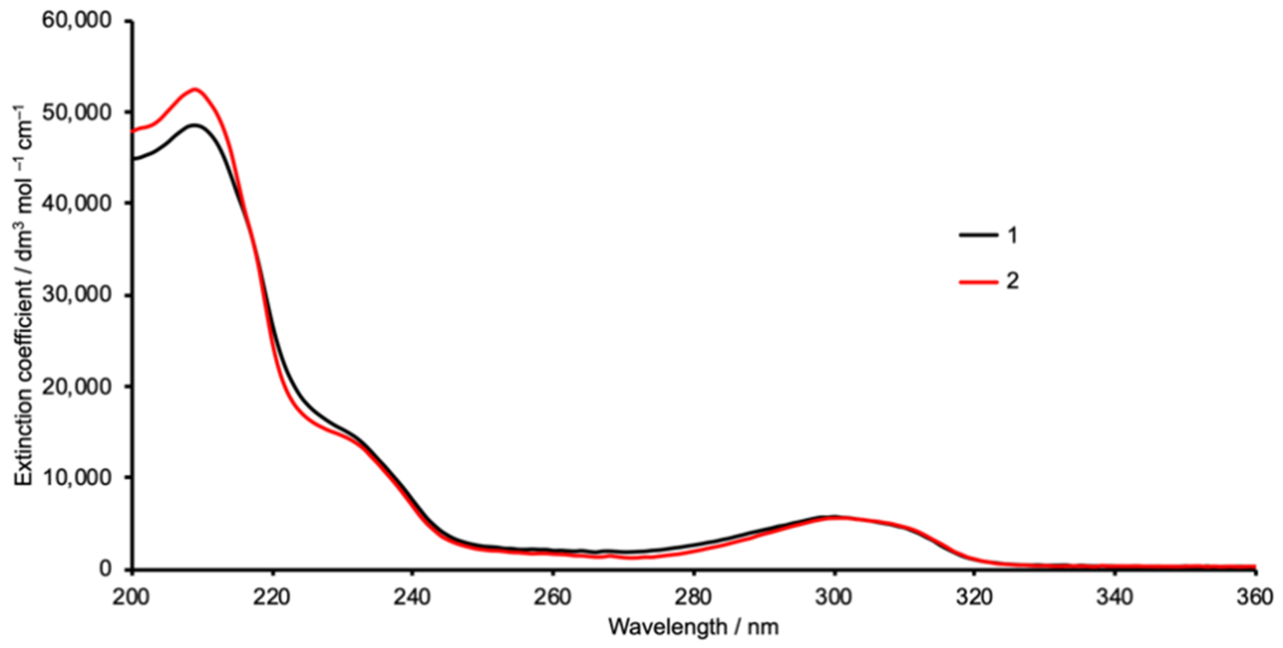
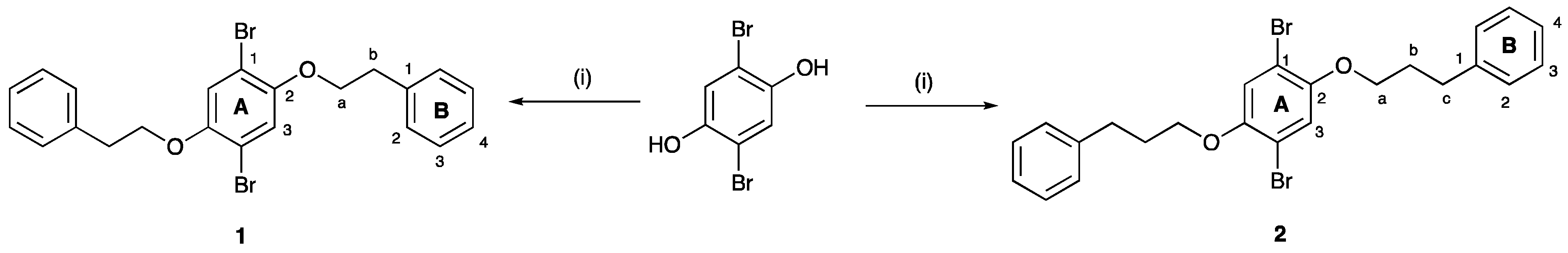
3.1. Synthesis and Characterization

Compounds 1 and 2 were prepared by the route shown in Scheme 3 which we have previously used for the synthesis of related 1,4-dibromo-2,5-bis(alkyloxy)benzene derivatives [33]. We find this strategy more convenient than the general methodology described by Neil and coworkers [34]. The base peaks in the high-resolution electrospray mass spectra (Figures S1 and S2 in the Supporting Material) arose from the [M + Na]+ ions at m/z = 498.9699 for 1, and m/z = 527.0017 for 2, and showed the characteristic dibromine isotope pattern. The 1H and 13C{1H} NMR spectra were assigned using NOESY, COSY, HMBC and HMQC spectra and were in accord with the structures displayed in Scheme 3. Figures S3–S8 show the 1H NMR, HMQC and HMBC spectra. The compounds were further characterized by FT-IR spectroscopy (Figures S9 and S10) and by solution absorption spectroscopy. The absorption spectra of 1 and 2 are similar (Figure 1), with bands at λmax 210, 232, and 300 (for 1) or 302 (for 2) nm arising from π*←π and π*←n transitions.

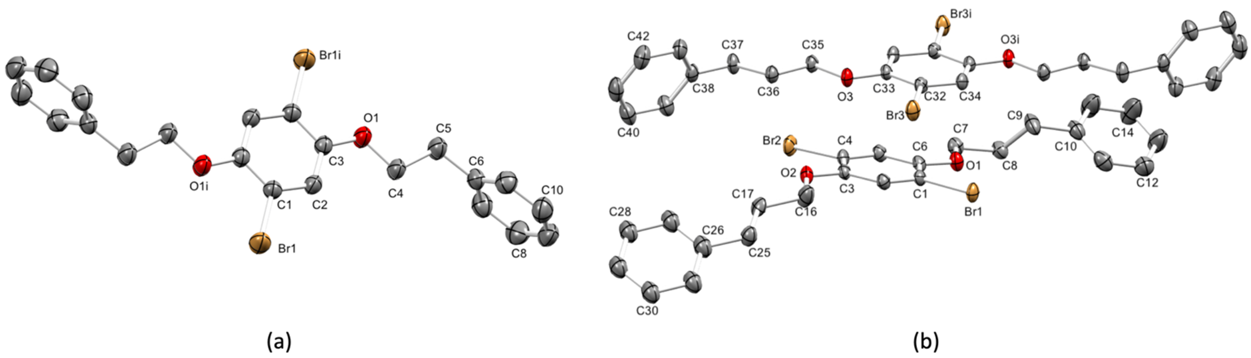
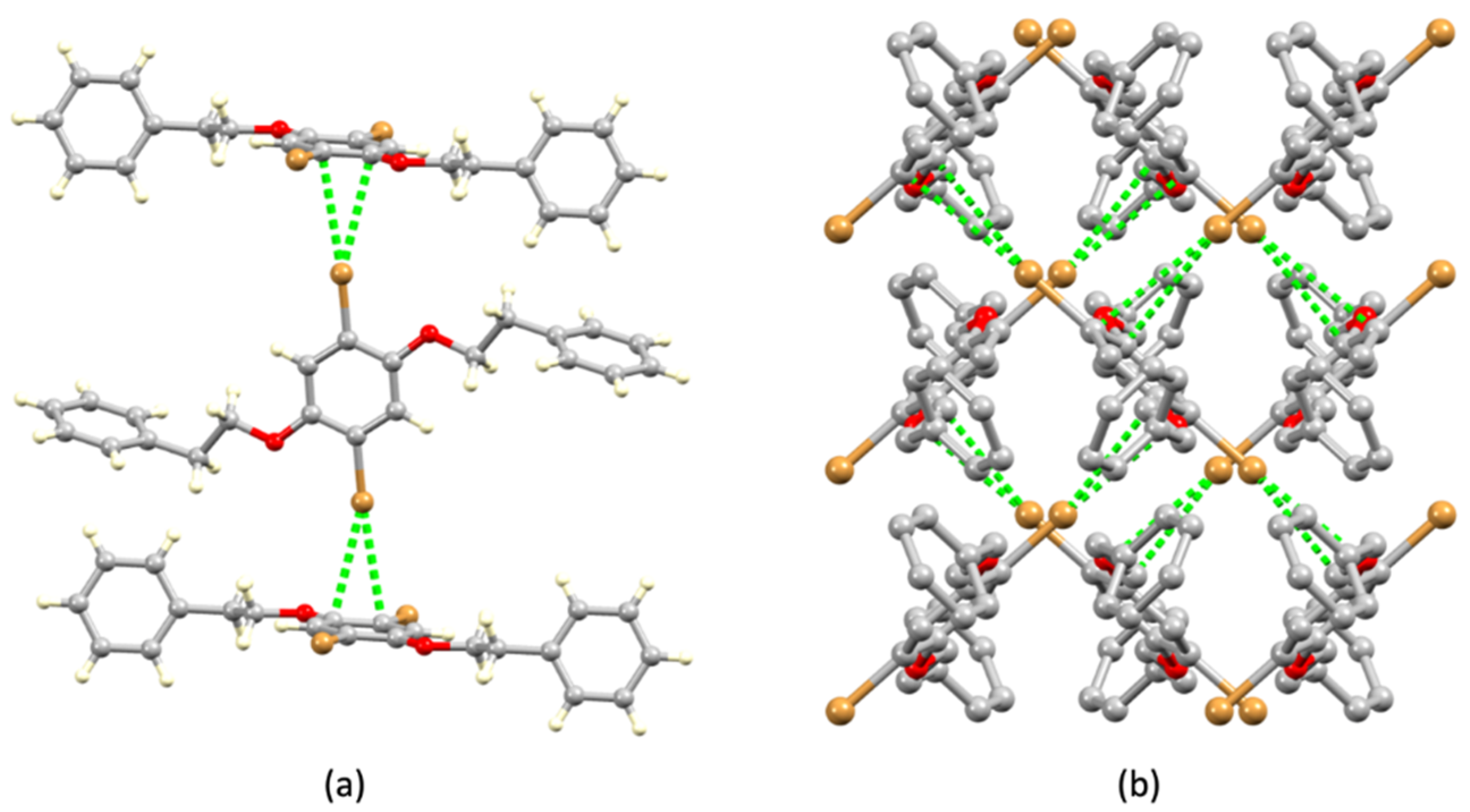
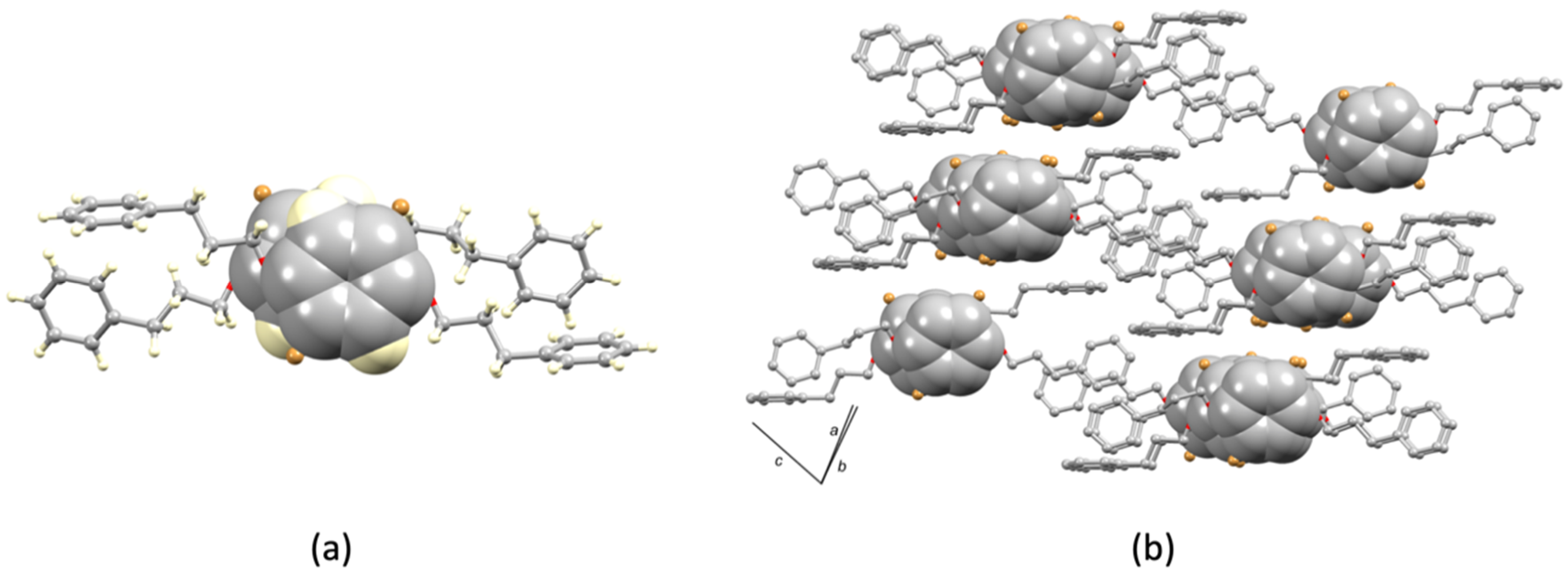
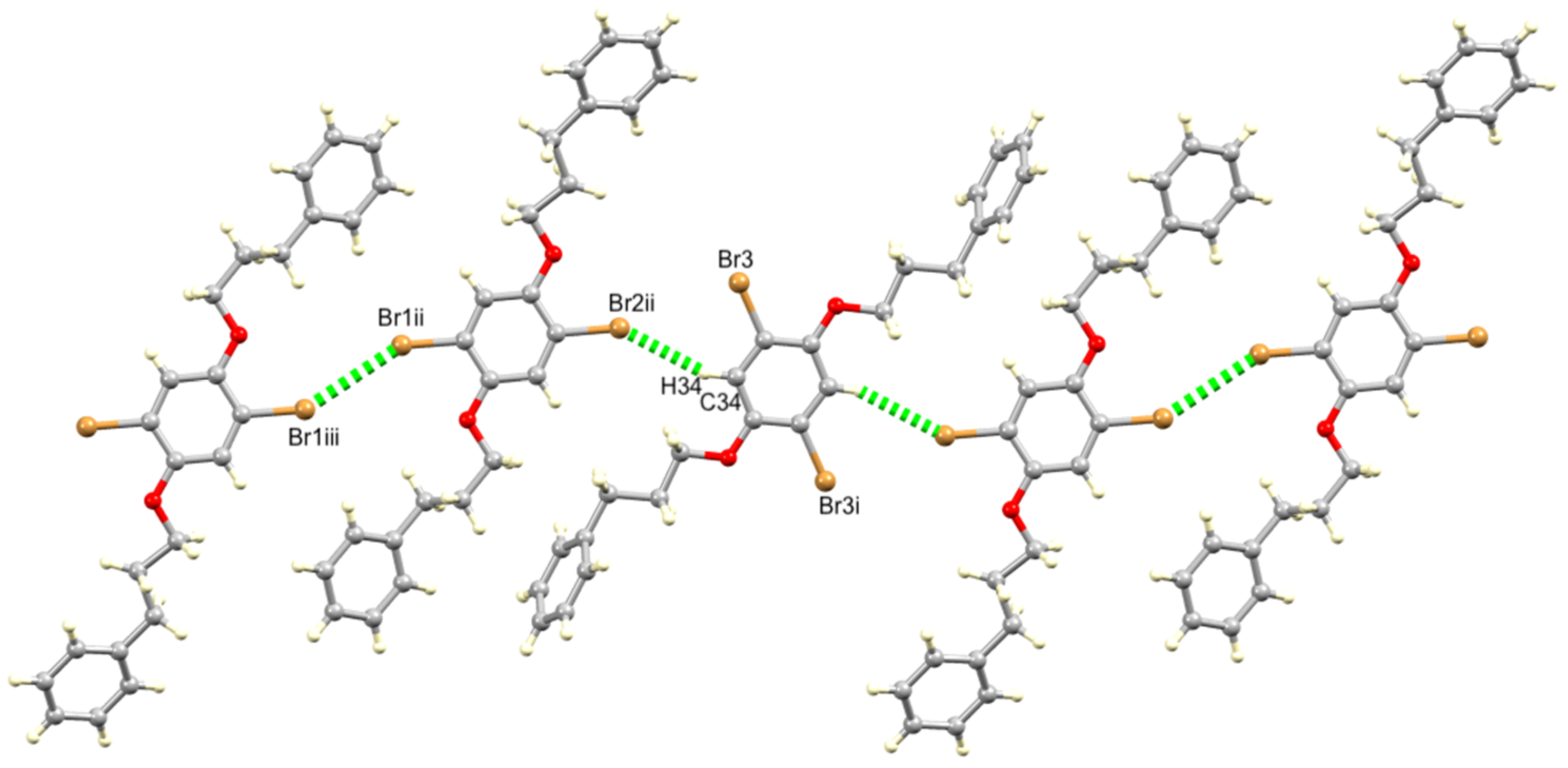
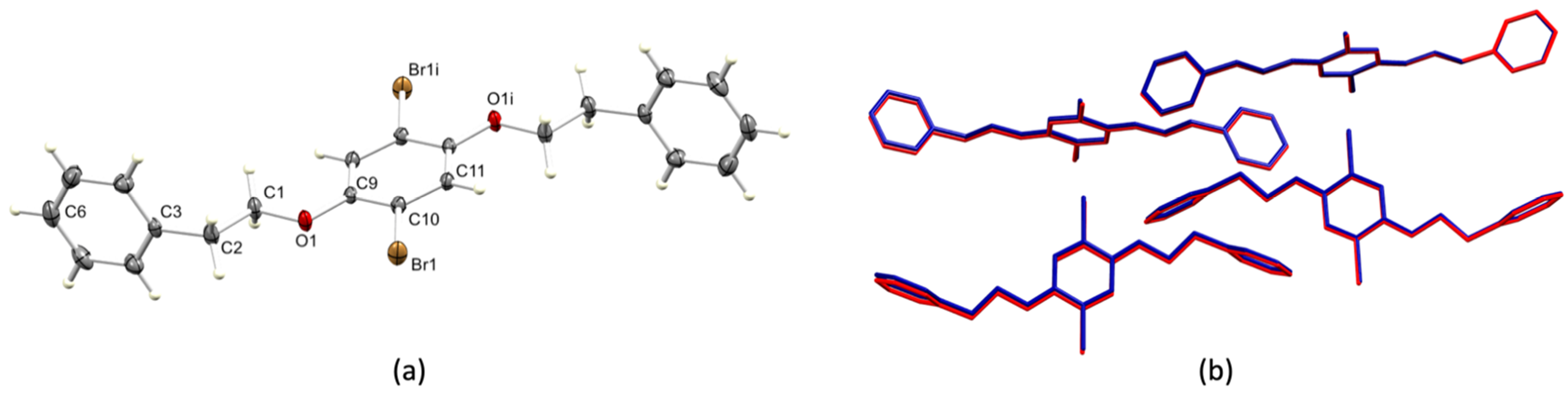
3.2. Single Crystal Structures of 1 (Polymorph I) and 2

Single crystals of 1 (polymorph I) and 2 were grown from hot solutions of the compounds in a mixture of MeOH and CHCl3 which was allowed to cool to room temperature. Both compounds crystallize in the triclinic space group P–1. The asymmetric unit for 1 (polymorph I) contains four crystallographically independent half-molecules, the second half of each being related to the first by inversion (Wyckoff sites d, b, c, and h for the molecules containing Br1, Br2, Br3, and Br4, respectively). The four molecules are conformationally and dimensionally similar (Figures S11 and S12) and we therefore focus on the bond parameters (Table 1) in the molecule containing atom Br1 (Figure 2a). The asymmetric unit of 2 contains one molecule and one half-molecule which are crystallographically independent. One 3-phenylpropoxy chain in the molecule containing atoms Br1 and Br2 is disordered and has been modelled over two sites of equal occupancies. The disorder affects the propoxy chain and the disordered terminal phenyl rings lie in planes differing by 16.0°, and twisted with respect to one another, as shown in Figure S13. Anisotropic behavior of the C10-C15 ring also indicates some slight disorder but this could not be modelled. Figure 2b illustrates the structures of the two independent molecules of 2. In both 1 and 2, the phenylalkoxy chains are in extended conformations. The Carene–O–Calkyl bond angles in 1 (polymorph I) and 2, and the shorter Carene–O compared to Calkyl–O bond lengths (Table 1) are indicative of sp2 hybridized O atoms and π-conjugation extending from the arene ring to the O atoms. In all independent molecules of 1 (polymorph I) and 2, the alkyloxy substituent adopts the same conformation relative to the central arene ring (Figure 2).
Each molecule of 1 (polymorph I) and 2 can be considered as a rod-like entity extending between the two para-carbon atoms of the phenyl rings. The introduction of the extra CH2 in each alkyloxy substituent leads to an elongation of the rod from ≈ 17.5 Å to 20.0 Å (distances between the para-C atoms of the terminal phenyl rings). This has a significant effect on the crystal packing. In polymorph I of 1, molecules containing Br1 and Br3 (see Figure S11 for atom labels) are arranged such that their central arene rings are approximately orthogonal with respect to each other (Figure 3a), and the same relationship is observed for molecules containing Br2 and Br4. This produces stacks of molecules (Figure 3a) with each Br atom directed towards the central arene ring of an adjacent molecule. Each Br atom engages in interactions with two C atoms, as depicted in Figure 3a. These can be classified as semi-localized C–Br...π(arene) interactions (Scheme 2b). Short contacts are Br1...C25i = 3.475(2) Å and Br1...C23ii = 3.529(2) Å (symmetry codes i = 1 − x, −y, −z; ii = 1 + x, −1 + y, z), with C1–Br1…C25i and C1–Br1…C23ii angles of 161.25(8) and 176.15(8)°. Similarly, Br4 forms two short contacts Br4...C12ii = 3.529(2) Å and Br4...C14iii = 3.468(2) A (symmetry code iii = 1 − x, 1 − y, 1 − z), with C34–Br4…C12ii and C34–Br4…C14iii angles of 176.22(8) and 160.54(8)°. Atoms Br2 and Br3 are involved in analogous interactions with arene rings containing C34iv and C36v, and C1iv and C3vi, respectively (symmetry codes: iv = x, 1 + y, z; v = 1 − x, 2 − y, 1 − z; vi = 1 − x, 1 − y, −z), at distances of 3.543(2), 3.449 (2), 3.541(2), and 3.516(2) Å and with C–Br…C angles of 176.14(8), 160.72(8), 176.14(8) and 161.28(8)°, respectively. Figure 3b illustrates the overall effect of these interactions within the lattice.
In contrast to solid-state structure of 1, the crystal packing in 2 is dominated by a combination of arene–arene π-stacking, C–H...Br hydrogen bonds, and short Br....Br contacts. The two independent molecules of 2 are involved in a face-to-face π-stacking interaction. The central arene rings are offset with respect to each other (Figure 4a) and the ring plane-to-centroid distance is 3.58 Å, with an inter-centroid distance of 3.76 Å. Crystal packing involves extension of the stacks as displayed in Figure 4b. Weak C–H...Br and Br...Br contacts interconnect the crystallographically independent molecules into ribbons as shown in Figure 5. The molecule containing Br1 and Br2 engages in both Br...Br and Br...H–C interactions, while atom Br3 has no significant short-contacts. In the molecule containing Br3, the C34–H34 unit acts as a hydrogen-bond donor. (Note that, as defined by Steiner [35], the C–H group is considered as a hydrogen bond donor.) Pertinent distances (defined in Figure 5) are C34–H34...Br2ii = 2.87Å, angle C34–H34...Br2ii = 159°, Br1ii...Br1iii = 3.4584(6) Å. This Br...Br separation is less than the sum of the van der Waals radii (3.70 Å) [15], and lies within the range of contacts found in the CSD [11]. The C–Br...Br–C interaction shown in Figure 5 belongs to the type I category (Scheme 1), and each C–Br–Br angle is 150.6(1)°.

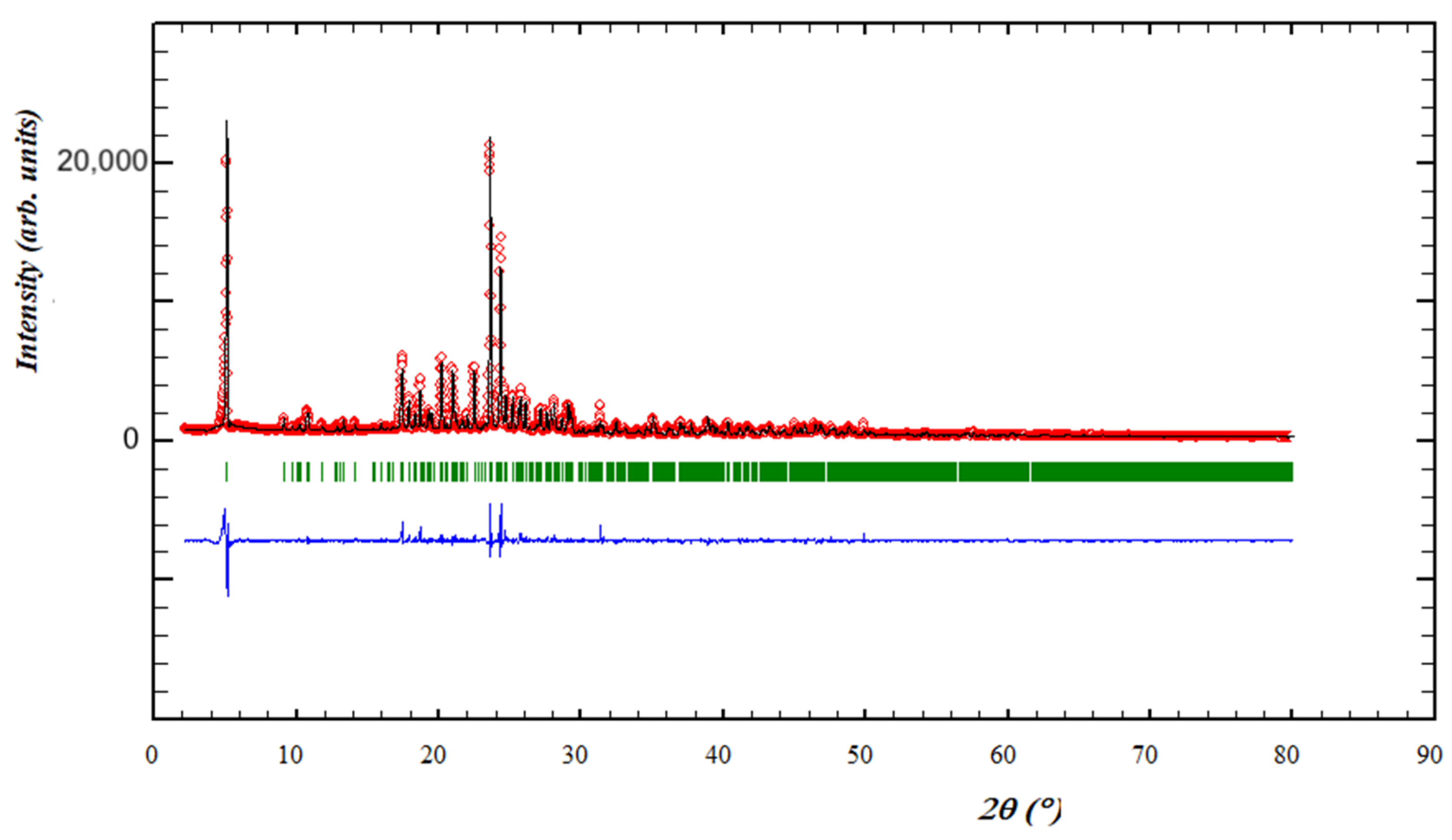
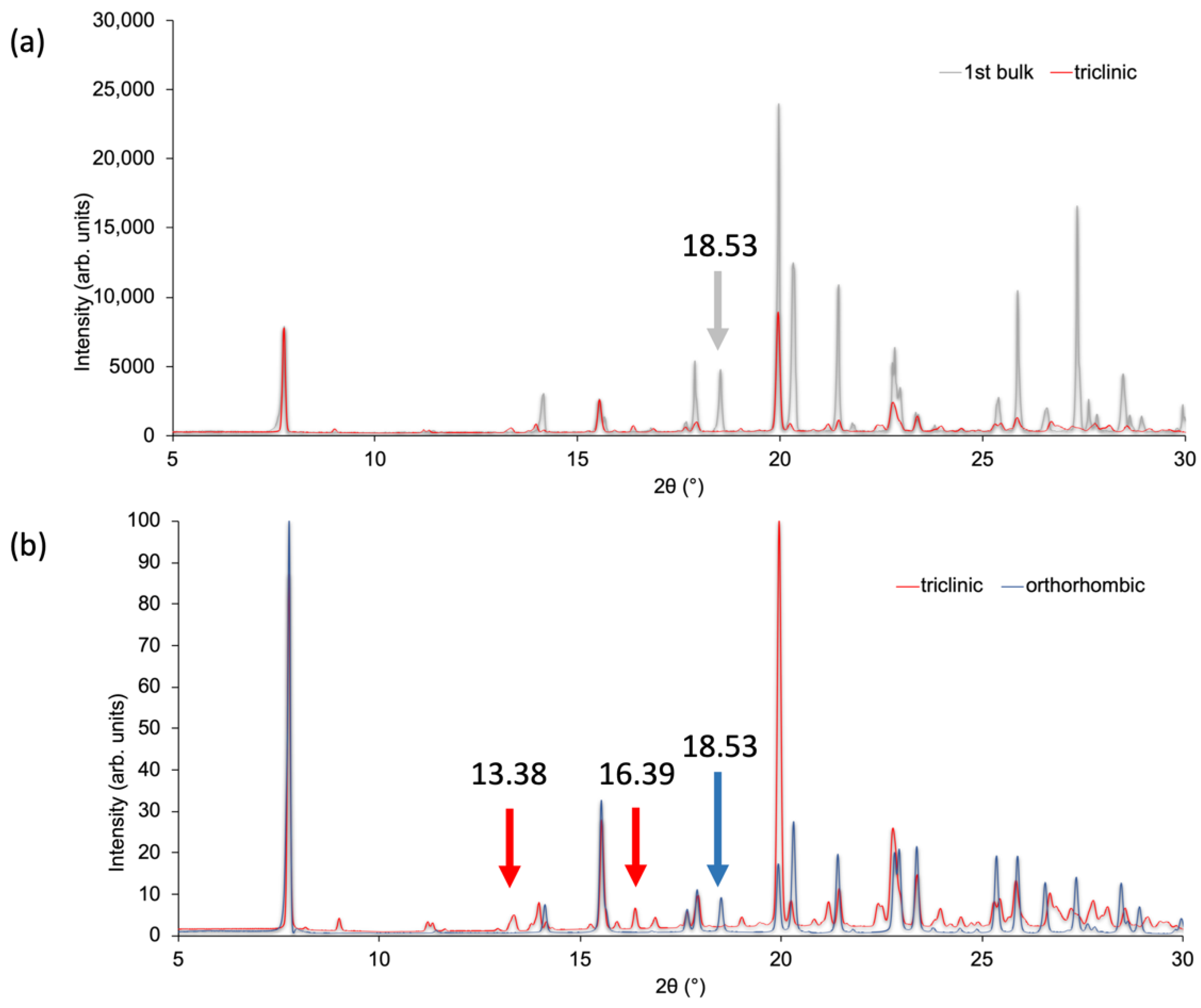
3.3. Powder XRD of Bulk Materials and a Second Polymorph of Compound 1

Even though 1 and 2 differ in their rod-like dimensionalities (see above), we considered it important to rule out the possibility of polymorphism as being responsible for the differences in crystal packing. Thus, the bulk materials were analysed by PXRD. The refinement for 2 (Figure 6) confirmed that the crystalline solid for 2 was representative of the crystal selected for single-crystal structural analysis. Peaks in the experimental plots match those in the fitted spectra, and the differences in intensities are explained in terms of differences in the preferred orientations.
For compound 1, the PXRD of the bulk material was not commensurate with the predicted pattern from the single crystal structure described above (Figure 7a and Figure S14). The high χ2 value of 121.2 and the appearance of peaks in the residuals (blue lines) with no matches in the predicted pattern confirmed that the single crystal was not representative of the bulk sample. The peak at 2θ = 18.53° (Figure 7a), in particular, has no match in the predicted pattern. Recrystallization of the ground powder used for the bulk material PXRD from a hot solution of MeOH and CHCl3 cooled to room temperature, yielded X-ray quality crystals. Cell checks on four crystals revealed a consistent set of cell parameters (Table 2) but the parameters differed slightly from those of the single crystal selected from the first batch of crystals (labelled polymorph I in Table 2). One crystal was, therefore, selected for single-crystal X-ray diffraction and the structure determination confirmed a second polymorph (II) of compound 1 which crystallized in the orthorhombic space group Pbca. The cell parameters are given in the last line of Table 2. The PXRD of this second recrystallized bulk sample was consistent with the pattern predicted from the single crystal structure data of polymorph II (Figure S15) with every line in the experimental pattern having a match with a peak in the predicted pattern. Figure 7b shows a comparison of the PXRD patterns predicted from the single-crystal data of the triclinic and orthorhombic polymorphs of 1. From the low angle data, several peaks can be picked as being diagnostic of a specific polymorph, and, using the peak at 2θ = 18.53°, we were able to confirm the presence of both polymorphs in the initial bulk sample.
The geometric center of polymorph II of 1 lies on a crystallographic inversion center (Wyckoff site 4b) (Figure 8a). The conformation of the molecule and the bond lengths and angles (caption to Figure 8a) are essentially the same as those in polymorph I (Table 1). The angle between the planes of the phenyl ring containing C3 and arene ring with C9 is 82.3°, and this compares to a range of values from 81.1° to 82.6° for the corresponding angles for the four independent molecules in polymorph I (Table 1). Figure 8b illustrates an overlay of the four independent molecules of polymorph I of 1 and the molecule of polymorph II with additional symmetry-generated molecules. This confirms that the relative positions of the molecules in the lattice are the same in the two polymorphs, and the packing interactions in polymorph II involve C–Br...π(arene) contacts, just as in polymorph I. Thus, we have demonstrated that while compound 1 exhibits polymorphism, it is not this phenomenon that is responsible for the differences in crystal packing between 1 and 2.

4. Conclusions

Two 1,4-dibromo-2,5-bis(phenylalkoxy)benzene derivatives 1 and 2 have been synthesized and characterized. Their single-crystal structures were determined, and the PXRD data for 2 confirmed that the single-crystal structure represents the bulk crystalline materials. For 1, analysis of the bulk material by PXRD led to the identification of two polymorphs (triclinic and orthorhombic) but with essentially the same molecular structures and the same packing interactions.
At the molecular level, 1 and 2 are similar with the phenylalkoxy chains in extended conformations, and the rod-like molecules have dimensions of ≈ 17.5 to 20.0 Å. This results in significant changes in the intermolecular interactions in the crystal lattices. The packing interactions in 1 are dominated by semi-localized C–Br...π(arene) contacts, with each Br located over one C–C bond of the central arene ring of an adjacent molecule. In 2, the packing involves a combination of C–H...Br hydrogen bonds, Br...Br interactions, and arene–arene π-stacking. We have also shown that while compound 1 exists in two polymorphic forms (I, triclinic, and II, orthorhombic), it is not this phenomenon that is responsible for the differences in crystal packing between 1 and 2.

Supplementary Materials

The following are available online at https://0-www-mdpi-com.brum.beds.ac.uk/article/10.3390/cryst11040325/s1: Figures S1 and S2: mass spectra of 1 and 2; Figures S3–S8: NMR spectra of 1 and 2; Figures S9 and S10: IR spectra of 1 and 2; Figures S11–S13: additional structural figures; Figures S14 and S15: PXRD data.

Author Contributions

Project conceptualization, administration, supervision, and funding acquisition, E.C.C. and C.E.H.; investigation and data analysis, G.M.; crystallography, A.P.; structure analysis and manuscript writing, C.E.H.; manuscript editing, G.M., A.P., and E.C.C. All authors have read and agreed to the published version of the manuscript.

Funding

This research was funded in part by the Swiss National Science Foundation, grant number 200020_182559.

Data Availability Statement

The data presented in this study are available on request from the corresponding author. The data are not publicly accessible at present.

Acknowledgments

We thank the University of Basel for support of our research.

Conflicts of Interest

The authors declare no conflict of interest.

References

  1. Desiraju, G.R.; Ho, P.S.; Kloo, L.; Legon, A.C.; Marquardt, R.; Metrangolo, P.; Politzer, P.; Resnati, G.; Rissanen, K. Definition of the halogen bond (IUPAC Recommendations 2013). Pure Appl. Chem. 2013, 85, 1711–1713. [Google Scholar] [CrossRef]
  2. Berger, G.; Fragville, P.; Meyer, F. Halogen bonding for molecular recognition: New developments in materials and biological sciences. Chem. Commun. 2020, 56, 4970–4981. [Google Scholar] [CrossRef]
  3. Cavallo, G.; Metrangolo, P.; Milani, R.; Pilati, T.; Priimagi, A.; Resnati, G.; Terraneo, G. The Halogen Bond. Chem. Rev. 2016, 116, 2478–2601. [Google Scholar] [CrossRef] [PubMed]
  4. Brammer, L.; Espallargas, G.M.; Libri, S. Combining metals with halogen bonds. CrystEngComm 2008, 10, 1712–1727. [Google Scholar] [CrossRef]
  5. Pancholi, J.; Beer, P.D. Halogen bonding motifs for anion recognition. Coord. Chem. Rev. 2020, 416, 213281. [Google Scholar] [CrossRef]
  6. Riel, A.M.S.; Rowe, R.K.; Ho, E.N.; Carlsson, A.-C.C.; Rappé, A.K.; Berryman, O.B.; Ho, P.S. Hydrogen Bond Enhanced Halogen Bonds: A Synergistic Interaction in Chemistry and Biochemistry. Acc. Chem. Res. 2019, 52, 2870–2880. [Google Scholar] [CrossRef]
  7. Varadwaj, P.R.; Varadwaj, A.; Marques, H.M. Halogen Bonding: A Halogen-Centered Noncovalent Interaction Yet to Be Understood. Inorganics 2019, 7, 40. [Google Scholar] [CrossRef]
  8. Zhu, Z.; Xu, Z.; Zhu, W. Interaction Nature and Computational Methods for Halogen Bonding: A Perspective. J. Chem. Info. Model. 2020, 60, 2683–2696. [Google Scholar] [CrossRef]
  9. Metrangolo, P.; Resnati, G. Halogen Bonding: A Paradigm in Supramolecular Chemistry. Chem. Eur. J. 2001, 7, 2511–2519. [Google Scholar] [CrossRef]
  10. Scholfield, M.R.; Vander Zanden, C.M.; Carter, M.; Ho, P.M. Halogen bonding (X-bonding): A biological perspective. Protein Sci. 2013, 22, 139–152. [Google Scholar] [CrossRef]
  11. Spilfogel, T.S.; Titi, H.M.; Friščić, T. Database Investigation of Halogen Bonding and Halogen...Halogen Interactions between Porphyrins: Emergence of Robust Supamolecular Motifs and Frameworks. Cryst. Growth Des. 2021, 21, 1810–1832. [Google Scholar] [CrossRef]
  12. Teyssandier, J.; Mali, K.S.; De Feyter, S. Halogen Bonding in Two-Dimensional Crystal Engineering. ChemistryOpen 2020, 9, 225–241. [Google Scholar] [CrossRef] [PubMed]
  13. Pedireddi, V.R.; Reddy, D.S.; Goud, B.S.; Craig, D.C.; Rae, A.D.; Desiraju, G.R. The Nature of Halogen...Halogen Interactions and the Crystal Structure of 1,3,5,7-Tetraiodoadamantane. J. Chem. Soc. Perkin Trans. 1994, 2, 2353–2360. [Google Scholar] [CrossRef]
  14. Tiekink, E.R.T. Supramolecular architectures sustained by delocalised C–I...π(arene) interactions in molecular crystals and the propensity of their formation. CrystEngComm 2021, 23, 904–928. [Google Scholar] [CrossRef]
  15. Bondi, A. van der Waals Volumes and Radii. J. Phys. Chem. 1964, 68, 441–451. [Google Scholar] [CrossRef]
  16. Janiak, C. A critical account on π–π stacking in metal complexes with aromatic nitrogen-containing ligands. J. Chem. Soc. Dalton Trans. 2000, 3885–3896. [Google Scholar] [CrossRef]
  17. Schollmeyer, D.; Shishkin, O.V.; Rühl, T.; Vysotsky, M.O. OH–π and halogen–π interactions as driving forces in the crystal organisations of tri-bromo and tri-iodo trityl alcohols. CrystEngComm 2008, 10, 715–723. [Google Scholar] [CrossRef]
  18. Shishkin, O.V. Evaluation of true energy of halogen bonding in crystals of halogen derivatives of trityl alcohol. Chem. Phys. Lett. 2008, 458, 96–100. [Google Scholar] [CrossRef]
  19. Prasanna, M.D.; Row, T.N.G. C–halogen··· π interactions and their influence on molecular conformation and crystal packing: A database study. Cryst. Eng. 2000, 3, 135–154. [Google Scholar] [CrossRef]
  20. Saraogi, I.; Vijay, V.G.; Das, S.; Sekar, K.; Row, T.N.G. C–halogen…π interactions in proteins: A database study. Cryst. Eng. 2003, 6, 69–77. [Google Scholar] [CrossRef]
  21. Robertson, C.C.; Perutz, R.N.; Brammer, L.; Hunter, C.A. A solvent-resistent halogen bond. Chem. Sci. 2014, 5, 4179–4183. [Google Scholar] [CrossRef]
  22. Palatinus, L.; Chapuis, G. Superflip—A Computer Program for the Solution of Crystal Structures by Charge Flipping in Arbitrary Dimensions. J. Appl. Cryst. 2007, 40, 786–790. [Google Scholar] [CrossRef]
  23. Palatinus, L.; Prathapa, S.J.; van Smaalen, S. EDMA: A Computer Program for Topological Analysis of Discrete Electron Densities. J. Appl. Cryst. 2012, 45, 575–580. [Google Scholar] [CrossRef]
  24. Dolomanov, O.V.; Bourhis, L.J.; Gildea, R.J.; Howard, J.A.K.; Puschmann, H. Olex2: A Complete Structure Solution, Refinement and Analysis Program. J. Appl. Cryst. 2009, 42, 339–341. [Google Scholar] [CrossRef]
  25. Sheldrick, G.M. Crystal Structure Refinement with ShelXL. Acta Cryst. 2015, C27, 3–8. [Google Scholar] [CrossRef]
  26. Bruker. Software for the Integration of CCD Detector System Bruker Analytical X-ray Systems; Bruker axs: Madison, WI, USA, 2013. [Google Scholar]
  27. Sheldrick, G.M. ShelXT-Integrated space-group and crystal-structure determination. Acta Cryst. 2015, A71, 3–8. [Google Scholar] [CrossRef]
  28. Macrae, C.F.; Sovago, I.; Cottrell, S.J.; Galek, P.T.A.; McCabe, P.; Pidcock, E.; Platings, M.; Shields, G.P.; Stevens, J.S.; Towler, M.; et al. Mercury 4.0: From visualization to analysis, design and prediction. J. Appl. Cryst. 2020, 53, 226–235. [Google Scholar] [CrossRef] [PubMed]
  29. LeBail, A.; Duroy, H.; Fourquet, J.L. Ab-initio structure determination of LiSbWO6 by X-ray powder diffraction. Mat. Res. Bull. 1988, 23, 447–452. [Google Scholar] [CrossRef]
  30. Pawley, G.S. Unit-cell refinement from powder diffraction scans. J. Appl. Cryst. 1981, 14, 357–361. [Google Scholar] [CrossRef]
  31. Rodríguez-Carvajal, J. Recent Advances in Magnetic Structure Determination by Neutron Powder Diffraction. Physica B 1993, 192, 55–69. [Google Scholar] [CrossRef]
  32. Roisnel, T.; Rodríguez-Carvajal, J. WinPLOTR: A Windows tool for powder diffraction patterns analysis Materials Science Forum. In Proceedings of the Seventh European Powder Diffraction Conference (EPDIC 7), Barcelona, Spain, 20–23 May 2000; pp. 118–123. [Google Scholar]
  33. Klein, Y.M.; Prescimone, A.; Neuburger, M.; Constable, E.C.; Housecroft, C.E. What a difference a tail makes: 2D→2D parallel interpenetration of sheets to interpenetrated nbo networks using ditopic-4,2′:6′,4″-terpyridine ligands. CrystEngComm 2017, 19, 2894–2902. [Google Scholar] [CrossRef]
  34. Moy, C.L.; Kaliappan, R.; McNeil, A.J. Aryl Trihydroxyborate Salts: Thermally Unstable Species with Unusual Gelation Abilities. J. Org. Chem. 2011, 76, 8501–8507. [Google Scholar] [CrossRef] [PubMed]
  35. Steiner, T. The Hydrogen Bond in the Solid State. Angew. Chem. Int. Ed. 2002, 41, 48–76. [Google Scholar] [CrossRef]
Scheme 1. Classification of halogen...halogen interactions. In type I, θ1 = θ2, and in type II, θ1 ≈ 180° and θ2 ≈ 90°.
Crystals 11 00325 sch001
Scheme 2. (a) Tiekink’s [14] criteria for identifying a C–X...π(arene) interaction: 160° ≤ α ≤ 180°, and the ring-centroid....X distance is 3.88 Å. (b) Classification of localized and semi-localized C–X...π(arene) interactions; for the semi-localized interaction, d1(C–X) is close in value to d2(C–X) [17,18].
Crystals 11 00325 sch002
Scheme 3. Synthetic route to compounds 1 and 2. Reaction conditions: (i) (2-bromoethyl)benzene or (3-bromopropyl)benzene, anhydrous K2CO3, DMF, 100 °C, 22 h. Yields: 1, 71.7% and 2, 87.3%. The ring and atom labelling for the NMR spectroscopic assignments are shown.
Crystals 11 00325 sch003
Figure 1. Solution absorption spectra of compounds 1 and 2 (MeCN, 2.0 × 10⁻⁵ mol dm−3).
Crystals 11 00325 g001
Figure 2. Molecular structures of (a) one of the crystallographically independent molecules of polymorph I of 1 (symmetry code i = −x, −y, −z), and (b) the two independent molecules of 2 (symmetry code i = −x, 1 − y, 1 − z). In 2, the 3-phenylpropoxy chain with C26 is disordered and only one position is shown; see text and Figure S13. Ellipsoids are plotted at the 40% probability level and H atoms are omitted for clarity.
Crystals 11 00325 g002
Figure 3. Packing of molecules of compound 1 (polymorph I) (a) Semi-localized interactions between each Br and two arene C atoms of adjacent molecules. (b) View down the c-axis illustrating orthogonal sets of Br...arene interactions; H atoms are omitted for clarity.
Crystals 11 00325 g003
Figure 4. (a) π-Stacking between the two crystallographically independent molecules of 2 with the C and H atoms of the stacked rings shown in space-filling representation. (b) Extension of the same π-stacking contacts through the lattice (H atoms are omitted for clarity).
Crystals 11 00325 g004
Figure 5. Alternating crystallographically independent molecules of 2 are associated into ribbons (symmetry code i = −x, 1 − y, 1 − z; ii = −1 + x, y, z; iii = −1 − x, −y, 1 − z).
Crystals 11 00325 g005
Figure 6. X-Ray diffraction (CuKα1 radiation) patterns (red circles) of the bulk crystalline material of 2 with fitting to the predicted pattern from single-crystal structure. The black lines correspond to the best fits from the Rietveld refinements, and green vertical lines show the Bragg peak positions. The blue line in each plot shows the difference between experimental and calculated points.
Crystals 11 00325 g006
Figure 7. (a) Comparison of the PXRD patterns (expansion of the range between 2θ = 5–30°) for the bulk sample from the first crystallization (grey) and the pattern predicted from the single-crystal data for the triclinic polymorph of 1 (red); the peak at 2θ = 18.53° arises from the second (orthorhombic) polymorph. (b) Comparison of the PXRD patterns (expansion of the range between 2θ = 5° and 30°, and normalized to maximum intensity = 100) predicted from the single-crystal data of the triclinic polymorph I of 1 (red) and of the orthorhombic polymorph II (blue); peaks at 2θ = 13.38° and 16.39° are representative of low angle data characteristic of polymorph I.
Crystals 11 00325 g007
Figure 8. (a) Molecular structure of 1, polymorph II (orthorhombic) with ellipsoids at 40% probability level. Symmetry code i: 1 − x, 1 − y, 1 − z. Selected bond parameters: C10–Br1 = 1.889(2), C9–O1 = 1.363(3), C1–O1 = 1.429(3) Å; C1–O1–C9 = 117.92(17)°. (b) Overlay of the four independent molecules of polymorph I of 1 (in red), and the molecule of polymorph II of 1 with additional symmetry-generated molecules; H atoms are omitted for clarity.
Crystals 11 00325 g008
Table 1. Selected bond lengths and angles in compounds 1 (polymorph I, for the molecule containing Br1) and compound 2 (both independent molecules A (with Br1 and Br2) and B (with Br3)).
Bond Parameter12 Molecule A2 Molecule B
C–Br/Å1.891(2) a1.889(3), 1.891(3)1.892(3)
Carene–O/Å1.361(3) a1.358(4), 1.363(4)1.365(4)
Calkyl–O/Å1.422(3) a1.434(4), 1.418(5)1.433(4)
Carene–O–Calkyl118.51(19) a117.7(3), 118.4(3)116.5(2)
Angle between planes of phenyl and central arene rings/°82.6 b29.3, 38.173.3
a Range of values for all four independent molecules: C–Br = 1.890(2) to 1.894(2) Å; Carene–O = 1.351(3) to 1.386(3) Å, Calkyl–O = 1.406(3) to 1.447(3) Å; Carene–O–Calkyl = 118.3(2) to 118.57(19)°. b The corresponding angles in molecules containing Br2, Br3 and Br4 are 81.6°, 82.3°, and 81.1°, respectively (see Figures S11 and S12).
Table 2. Cell parameters for polymorphs I and II of 1, and for four crystals selected from the recrystallization of the bulk sample.
Crystalabcα/Degβ/Degγ/Deg
Polymorph I (P–1) a8.2806(13) 10.6327(16)22.885(4)91.027(14)91.663(14)89.806(13)
Recrystallized bulk, crystal 1 b8.23 c10.5522.8489.8889.8189.93
Recrystallized bulk, crystal 2 a8.22 c10.5222.7889.9789.9289.99
Recrystallized bulk, crystal 3 a8.22 c10.5222.7689.9989.9890.00
Recrystallized bulk, crystal 4 a8.21 c10.5222.7790.0790.0790.05
Polymorph II (Pbca) a10.5176(7)8.2178(5)22.7853(14)909090
a Measured at 200 K; b measured at 150 K; c the axis order has been chosen for direct comparison with those of polymorph I.
Publisher’s Note: MDPI stays neutral with regard to jurisdictional claims in published maps and institutional affiliations.

