
Comparative Study of High-Performance Concrete Characteristics and Loading Test of Pretensioned Experimental Beams


1
Department of Structures, Faculty of Civil Engineering, VSB–Technical University of Ostrava, Ludvíka Podéště 1875/17, 708 33 Ostrava-Poruba, Czech Republic
2
Department of Building Materials and Diagnostics of Structures, Faculty of Civil Engineering, VSB–Technical University of Ostrava, Ludvíka Podéště 1875/17, 708 33 Ostrava-Poruba, Czech Republic
3
Centre of Building Experiments, Faculty of Civil Engineering, VSB–Technical University of Ostrava, Ludvíka Podéště 1875/17, 708 33 Ostrava-Poruba, Czech Republic
*
Author to whom correspondence should be addressed.
Crystals 2021, 11(4), 427; https://0-doi-org.brum.beds.ac.uk/10.3390/cryst11040427
Submission received: 12 March 2021
/
Revised: 9 April 2021
/
Accepted: 13 April 2021
/
Published: 15 April 2021
(This article belongs to the Special Issue Properties and Performance of Concrete Materials and Structures)
Abstract
:High-performance concrete (HPC) is subjected to wide attention in current research. Many research tasks are focused on laboratory testing of concrete mechanical properties with specific raw materials, where a mixture is prepared in a relatively small amount in ideal conditions. The wider utilization of HPC is connected, among other things, with its utilization in the construction industry. The paper presents two variants of HPC which were developed by modification of ordinary concrete used by a precast company for pretensioned bridge beams. The presented variants were produced in industrial conditions using common raw materials. Testing and comparison of basic mechanical properties are complemented with specialized tests of the resistance to chloride penetration. Tentative expenses for normal strength concrete (NSC) and HPC are compared. The research program was accomplished with a loading test of model experimental pretensioned beams with a length of 7 m made of ordinarily used concrete and one variant of HPC. The aim of the loading test was to determine the load–deformation diagrams and verify the design code load capacity calculation method. Overall, the article summarizes the possible benefits of using HPC compared to conventional concrete.
1. Introduction
High-performance concrete (HPC) is not a new player in the field of concrete construction. The beginning of the HPC era is connected with the development of superplasticizers together with the use of mineral admixtures finer than cement in the 1970s and 1980s. Though HPC is no longer a novelty [1], it is still an object of interest of many research activities in a few fields.
Scientific work has been focused primarily on the design of suitable concrete mixtures. For HPC, a low water to binder ratio is required. The concrete mixture has to contain a well-compatible superplasticizer and an optimum composition of the binding system [2].
Replacement of part of the cement with mineral admixtures finer than cement helps, among others, to reach significantly better consistency. As a mineral admixture, silica fume is widely used, and another possibility is the utilization of metakaolin. The advantage of metakaolin is the possibility for it to be one of the compounds of a ternary binder, as it contains alumina ions, and together with calcium carbonate (ground limestone), it can create a good base for a ternary binder. In addition, ternary binders with metakaolin are considered as a very effective arrangement for the reduction in expansion caused by the alkali–silica reaction [3].
Considering the fact that HPCs are usually based on a high portion of cement, it is also necessary to deal with impact on the environment (e-CO2 and e-Energy) [4,5] and compare it with other materials from the point of view of sustainability [6].
The topics of life cycle analysis and environmental impact are closely connected with the material durability and structural service life [7,8]. Concrete durability could be assessed in a few aspects, including testing of carbonation, frost resistance or testing of resistance to chloride penetration. HPC possesses increased durability thanks to its compact microstructure [9,10]. High frost resistance [11], carbonation resistance [12,13] and chloride resistance [14,15] were proved in a few research tasks. Research, which is referred to in [16], indicates that the frost resistance of concretes with metakaolin is more favorable than that of concretes with silica fume.
Parallel with the progress in technology, it is also important to amend design codes and rules for construction [17,18]. Model code 2010 [19] reflects the utilization of HPC with increasing validity for concrete up to the compressive strength of 140 MPa. From this point of view, experimental tests of structural elements made of new types of concrete are very valuable as a verification of load capacity calculation models given in design codes and as a background for numerical modeling. Testing of load-bearing elements is demanding with respect to production, manipulation, transport and the requirement of commonly unavailable testing equipment, and that is why it is less frequentative.
Scientific papers in the field of HPC are usually focused narrowly on mechanical properties [20], compressive strength and microstructure [21], influence of high temperature [22] or, on the other hand, on testing of structural elements [23,24,25].
The presented paper reflects the mentioned experiences in complex research which starts with the development of an HPC mixture, continues with the description of the microstructure and material mechanical properties and load capacity testing of the experimental structural element, proves the increased resistance to environmental effects and brings forth a possible application in load-bearing structures and the primary quantification of expenses. A complex approach with emphasis on application in the construction industry is the preference of the presented research.
Based on extensive and long-term parametrical laboratory testing, two variants of an HPC mixture were designed using common raw materials. The subobjective was to prove the mechanical properties of concrete developed in the laboratory in industrial conditions with respect to the amount of mixture, fresh concrete transport and casting conditions.
The research program was complemented with the testing of the load capacity of a pretensioned structural element. The aim of the loading test was the verification of the calculation model for bending moment load capacity used in the current code for concrete with compressive strength on the border or outreaching the limits of validity. A comparison of the reserve in load capacities with the calculated value of the structural element made of common concrete and HPC is presented.
Utilization of HPC is also connected with an expected improved durability. The developed variants of HPC are intended to be used preferably in bridge beams which are exposed to chloride aerosols due to traffic on or under the bridge, and that is why testing of chloride resistance was given priority. New variants of HPC show, on the basis of the performed test, higher resistance to chloride penetration, which is promising from the perspective of durability.
Tentative expenses on used materials are compared not only for testing beams but also on an example of a model bridge structure. Though this comparison cannot consider all of the problematic life cycle cost quantification, it has a meaning for the basic notion of the economy aspect of using HPC in the traditional cross-section of pretensioned beams.
2. Concrete Mixture and Material Properties of Concrete
The industrial partner of the presented research is a traditional producer of precast pretensioned and post-tensioned bridge beams. The concrete composition has to be adapted to the volume of the mixture device, which is 1 m3, and fulfill the requirements of workability and compaction of fresh concrete, together with a target of high early strength.
The current concrete mixture used for pretensioned elements is stated in Table 1 and, in this paper, is identified as normal strength concrete (NSC) and listed as the reference concrete. The concrete composition is based on ordinary Portland cement. High-quality granite aggregates 4/8 and 8/16 from the quarry in Litice nad Orlici and sand 0/4 from Lipa nad Orlici belong to local natural resources. The amount of plasticizer is 4.5 l per m3. The water cement ratio of NSC is 0.4.
Based on long-term and extensive laboratory work on composition optimization [26,27], the NSC concrete mixture was modified to develop an HPC mixture. In Table 1, the composition of two variants of the HPC mixture is shown, identified as HPC1 and HPC2. Concrete mixture HPC1 preserves the utilization of the 8/16 aggregate, while in concrete mixture HPC2, aggregate 8/16 is replaced with 0/4 and 4/8 aggregates. Utilization of HPC2 without the 8/16 aggregate is profitable, especially for subtle elements with dense reinforcement. Another advantage is only needing minimum vibration due to the fine-grained composition.
Both variants of HPC were designed with ternary binders using slag and limestone. The ordinarily used plasticizer was replaced with a superplasticizer, based on polycarboxal ethers, due to the low water–cement ratio, which is, respectively, 0.29 and 0.25. Low water–cement and water–binder ratios cause deterioration of workability, and the mixture shows a sticky consistency if only Portland cement is used. Replacing part of the cement with mineral admixtures finer than cement helps to achieve a better consistency. In the presented HPC mixture, metakaolin was used as a mineral admixture. The consistency of all analyzed concretes was classified as superfluid on the basis of the cone slump test, where the slump was over 210 mm. The result of the optimization is a mixture with high early strength as an effect of the ternary binder. Based on previous research, it is supposed that the designed HPC possesses high frost resistance with a minimum risk of the alkali–silica reaction [3,16].
The main advantage of HPC is its dense microstructure, which is a premise for the high strength and high durability. The dense microstructure is a consequence of the very low water to binder ratio. The microstructures of common concrete and HPC are compared in Figure 1.
In Table 2, the test results of the basic mechanical properties of NSC and HPC variants are shown. Laboratory testing was carried out according to valid codes [28,29,30]. The split tensile strength of HPC was tested on cube specimens both in directions parallel (six specimens) and perpendicular to the filling (three specimens). The mixed mode fracture resistance together with the tensile strength of the analyzed types of concrete is discussed in [31,32].
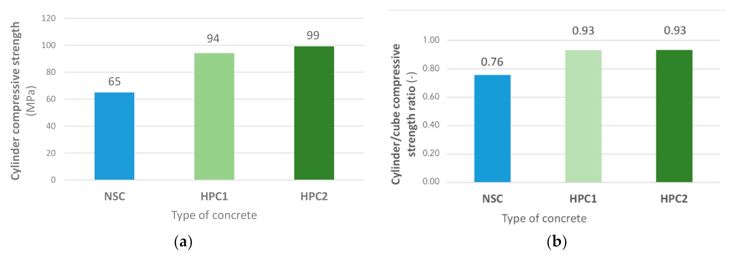
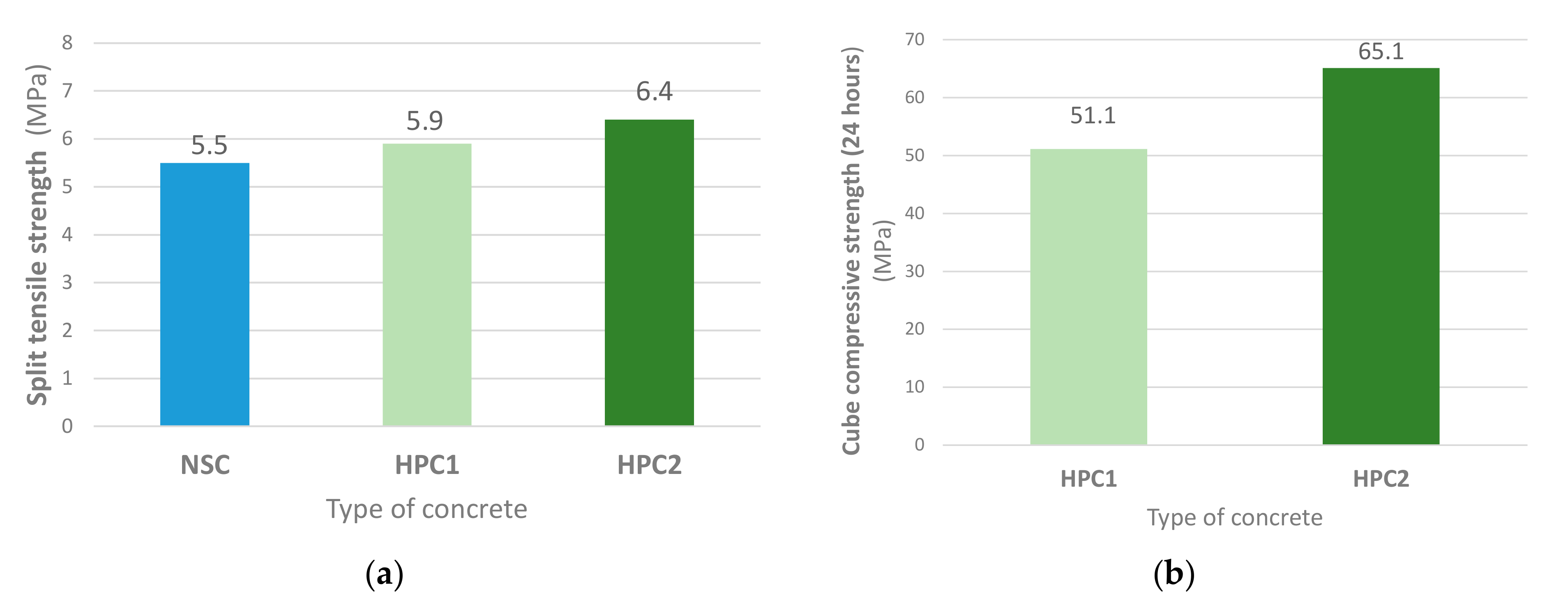
In Figure 2, comparisons of the cylinder compressive strength of NSC and variants of HPC are presented. The increment in cylinder compressive strength is, respectively, 45% and 52%. The value of the cylinder/cube compressive strength ratio is 0.76 for NSC and 0.93 for both variants of HPC. Values of the cylinder/cube compressive strength ratio correspond to the expected values, which are, for NSC, 0.8–0.85 and, for HPC, 0.9–1.0. The increment in the static modulus of elasticity of HPC is 16%, and 18% for the second variant. Values of the modulus of elasticity are slightly lower but roughly correspond to the values expected according to the design code [17] both for NSC and HPC. Values of the split tensile strength are compared in Figure 3. The cube compressive strength of HPC variants in 24 h is compared in Figure 3, and it reaches 50% and 60% of the cube compressive strength in 28 days.
3. Durability of Concrete
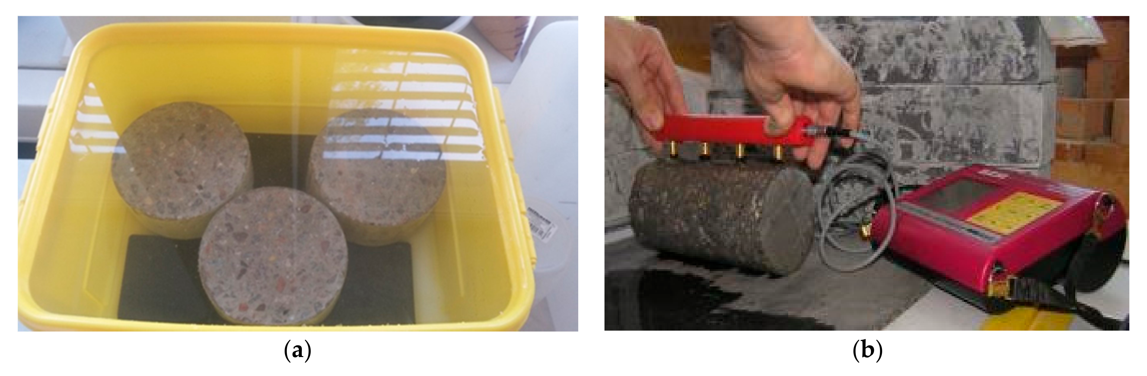
Resistance to chloride penetration is characterized with a diffusion coefficient Dc and an aging factor m. AASHTO TP-95 tests [33] were carried out (Figure 4), where a surface electrical resistance was measured for six time points for the determination of the diffusion coefficient, which changes with the maturing of concrete, as a function of time. The reference aging factor m was derived based on those values. A higher aging factor represents an increasing resistance to chloride penetration over time, which may be related to a higher persistence of the concrete structure to aggressive substances. The reference diffusion coefficient based on the NT-BUILD 443 method [34] was also evaluated. Results of the tests are stated in Table 3, Table 4 and Table 5.
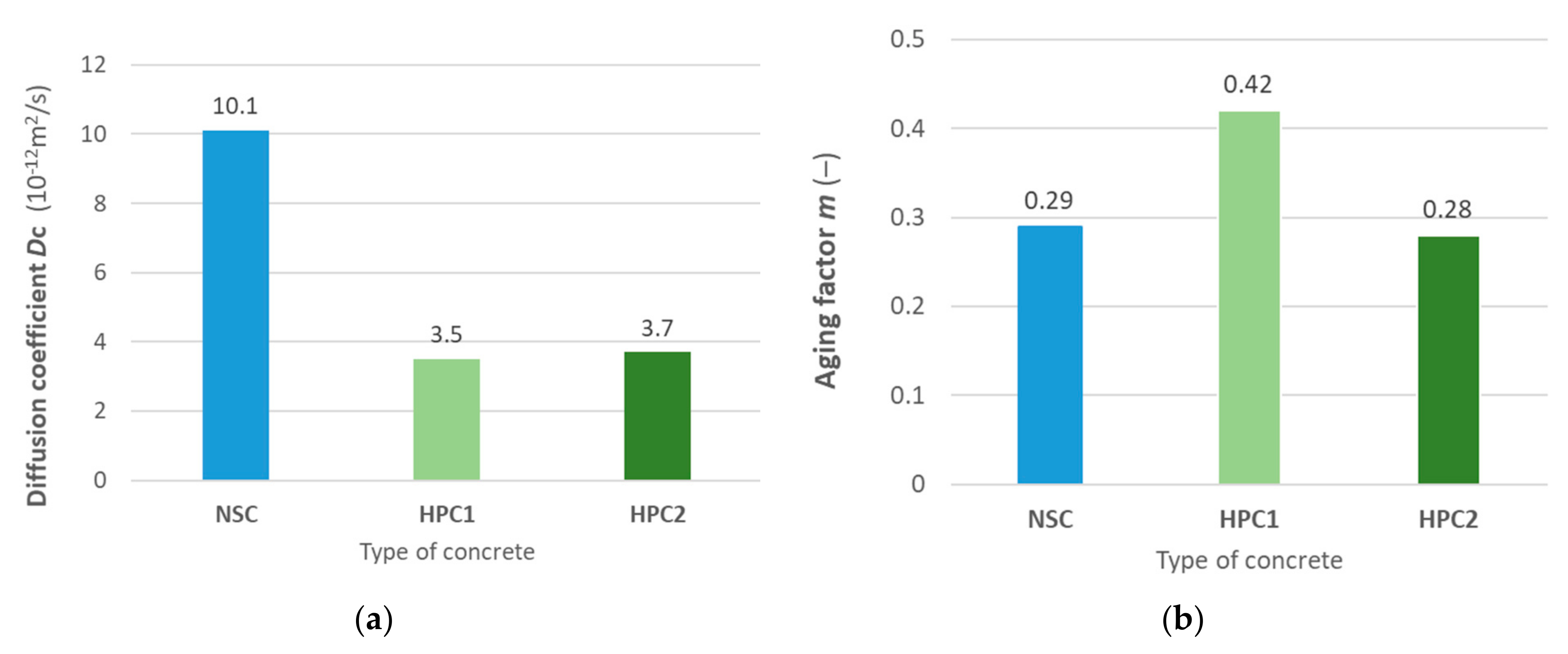
In Figure 5, the diffusion coefficient and aging factor of the analyzed concretes are compared. The diffusion coefficient is about 3 times lower both for HPC1 and HPC2 than for NSC according to Nord 443. The aging factors of NSC and HPC2 are almost the same, and the aging factor of HPC1 is considerably more favorable than the NSC value. A more detailed description of the testing and discussion of results can be found in [35,36,37].
4. Experiments of Pretensioned Concrete Beams
4.1. Description and Production of Experimental Beams
The background for the experimental beam design was the portfolio of bridge beams of the industrial partner, which is composed mainly of slab beams and T-shaped beams. It was also necessary to take into consideration the disposition of Centre of Building Experiments at VSB-TUO (CBE), especially the load and space capacity of the testing device, where the limit specimen width is 900 mm and the limit span is 10 m. It was decided to use a modified slab beam, which roughly corresponds to the real structural element, rather than a T-shaped beam, whose cross-section would have to be modified due to the space and loading capacity of the CBE device. Variant HPC2 was selected for experimental beam production.
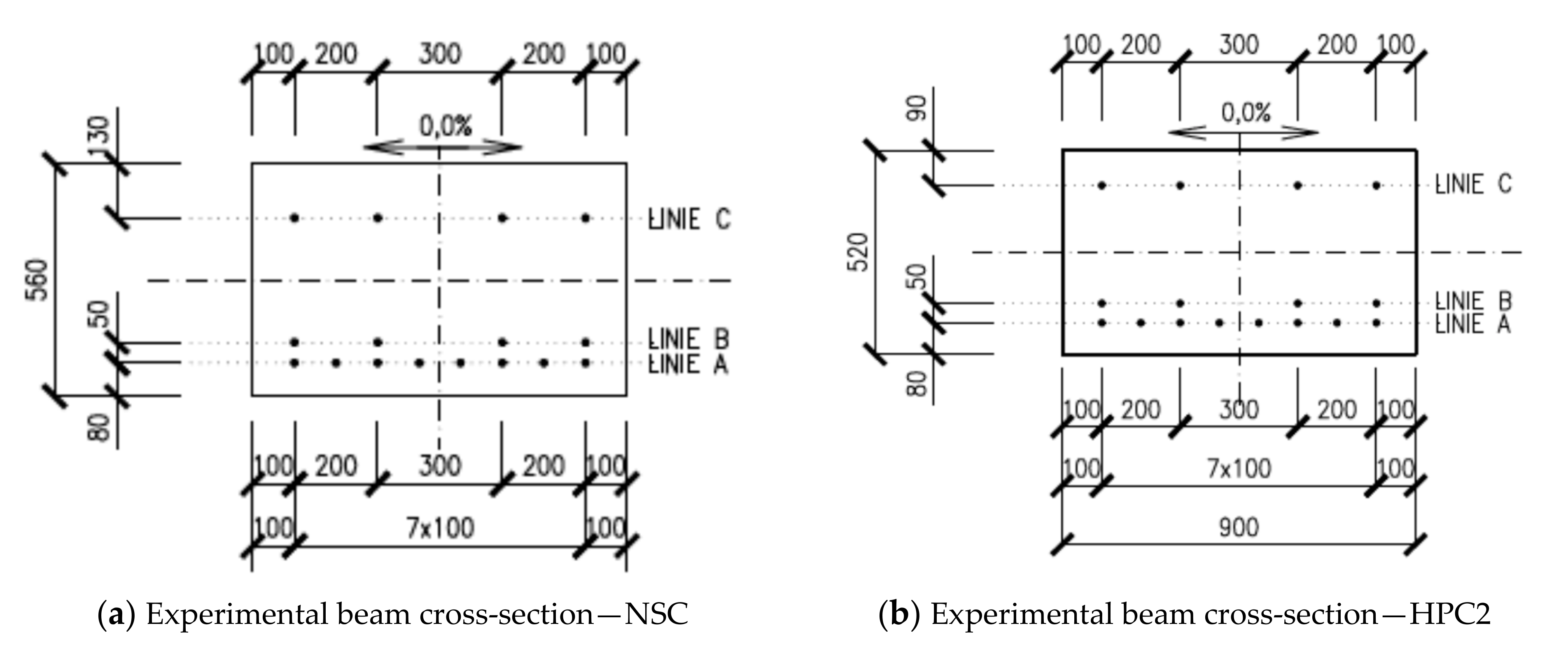
The criterion for the design of cross-sectional dimensions was the same flexural stiffness of the experimental beam’s cross-section both for NSC and HPC2. Slab beams were designed with the width of 900 mm and the height of 560 mm for the beam made of NSC, and 520 mm for the beam made of HPC2, Figure 6. The height of experimental beams corresponds to the expected height of a real slab bridge beam. The length of the beams was 7.0 m, and the span was 6.5 m. The length was limited by the crane load capacity in CBE.
The pretensioned reinforcement with a diameter of 15.7 mm and a strength of 1860 MPa was designed in three rows with a similar layout in both NSC and HPC cross-sections, Figure 6. The upper layer of the pretensioned reinforcement was designed to reduce the negative deformation. Together with the bottom pretensioned reinforcement, which is partially provided with separation, it eliminates tensile stress on the element’s upper surface. Initial stress was 1400 MPa in all pretensioned reinforcements. Stress after releasing was calculated with a value of 1312 MPa and stress after long-term changes was 1129 MPa in the bottom layer of the pretensioned reinforcement.
There was also non-pretensioned reinforcement designed with a yield stress of 500 MPa. Four-legged stirrups with a profile of 8 mm and a distance in the longitudinal direction of 150 mm were designed to bear the shear force and to ensure accessories for manipulation. Stirrups were complemented with longitudinal reinforcement, with a profile of 16 mm.
Experimental beams were designed with approximately the same load capacity and cracking moment. Bending moment load capacities, cracking moments and appropriate loading forces together with testing peak load force are compared in Table 6. Load capacities were calculated according to the design code [17], based on the limit strain method, using the software IDEA statica [38]. Mean values of compressive and tensile strengths based on the test results were considered. Probabilistic assessment of the time-dependent load capacity is discussed in [39]. Cracking moment was calculated using the value of the pretensioned force in the appropriate time with respect to long-term changes. The designed shear reinforcement allows presupposing the bending failure of experimental beams.
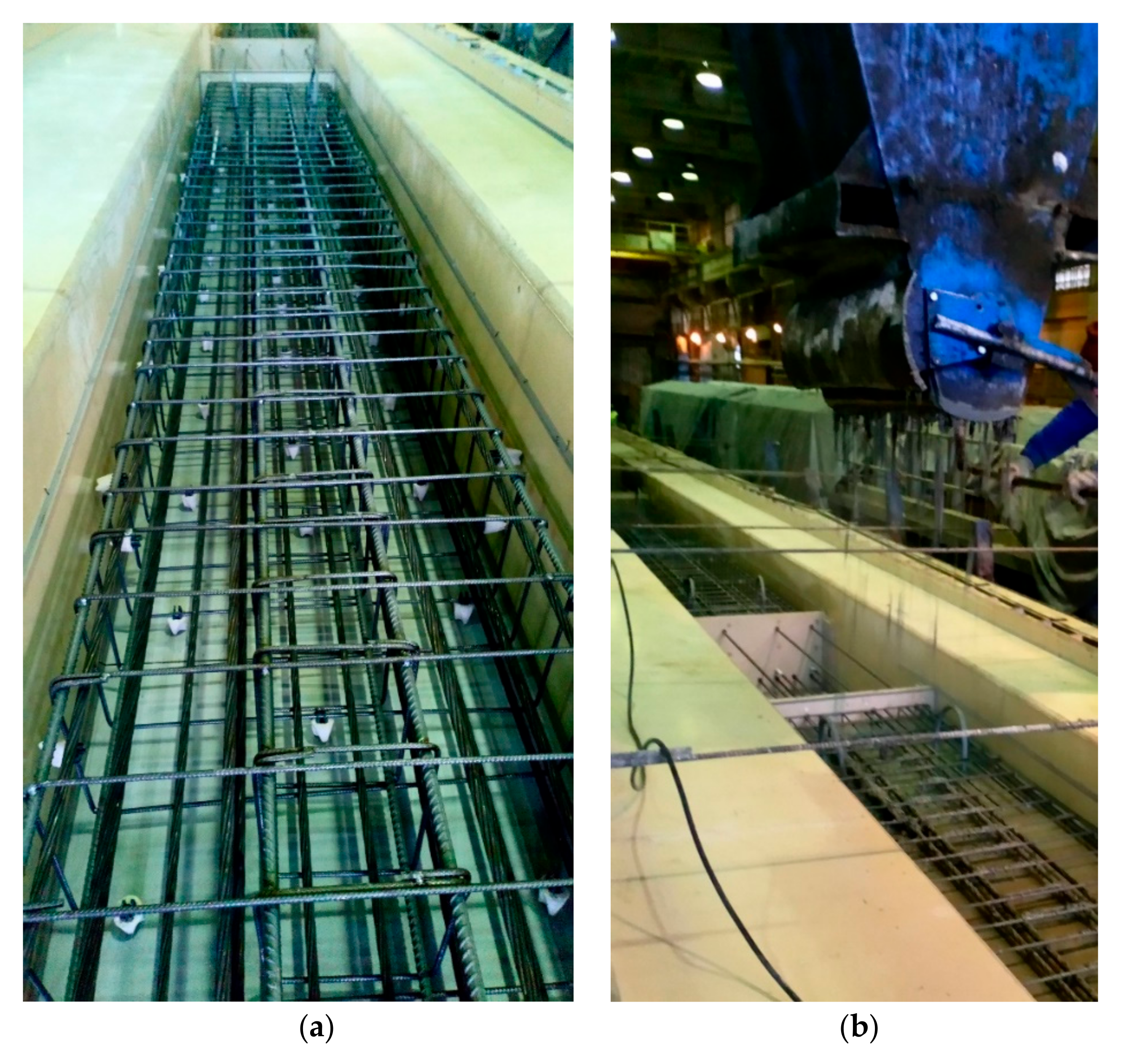
Experimental beams were produced in the manufacturing plant of the industrial partner, Figure 7. Together with the experimental beams, specimens for laboratory testing were also concreted. Results of laboratory testing are listed in Chapter 2–Chapter 3 of this paper.
4.2. Testing of Experimental Beams
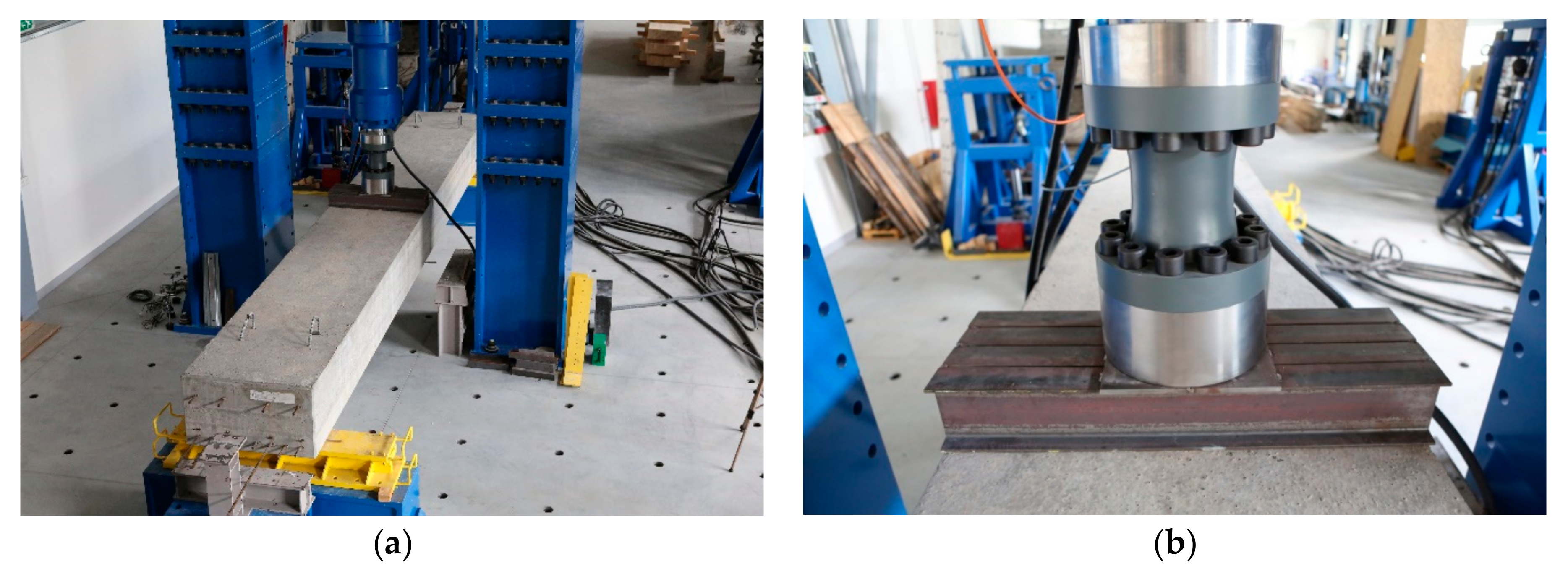
Experimental beams were exposed to a three-point loading test, Figure 8. Three beams were tested, one made of NSC and two made of HPC2. The testing frame equipped with a system of hydraulic cylinders allowed achieving a loading force up to 2000 kN. The loading force was recorded with a hydraulic electronic control system, and the deflection in the mid-span was measured with a precision of 0.01 mm. Initial negative deformation due to pretension was not measured. The concentrated load of the hydraulic cylinder was spread to the width of the experimental beam with the steel welded element, Figure 8. Experimental beams were supported with cylinder bearings to draw the supports close to the hinge support. The application of the load was controlled with deformation, and the loading step was 5 mm. After applying the load in one step, there was a 5–10 min time delay for the deformation setting.
The tested peak load of the NSC experimental beam was 1148 kN and there is about 18% reserve when compared with the calculated value of the load capacity. The load x mid-span deflection diagram (LD diagram) is shown in Figure 9. Yielding of the reinforcement is apparent in the diagram, the rupture of pretensioned reinforcement was reached and there was also significant damage of the concrete in the compressed part of the cross-section, where also buckling of the compressed non-pretensioned reinforcement emerged, Figure 10. The first visible cracks, with a width of 0.05/0.1 mm, appeared for a loading force of about 586 kN. This value is also distinct in the diagram, and with this value of the loading, the linear part of the LD function finishes. The calculated value of the cracking force is lower.
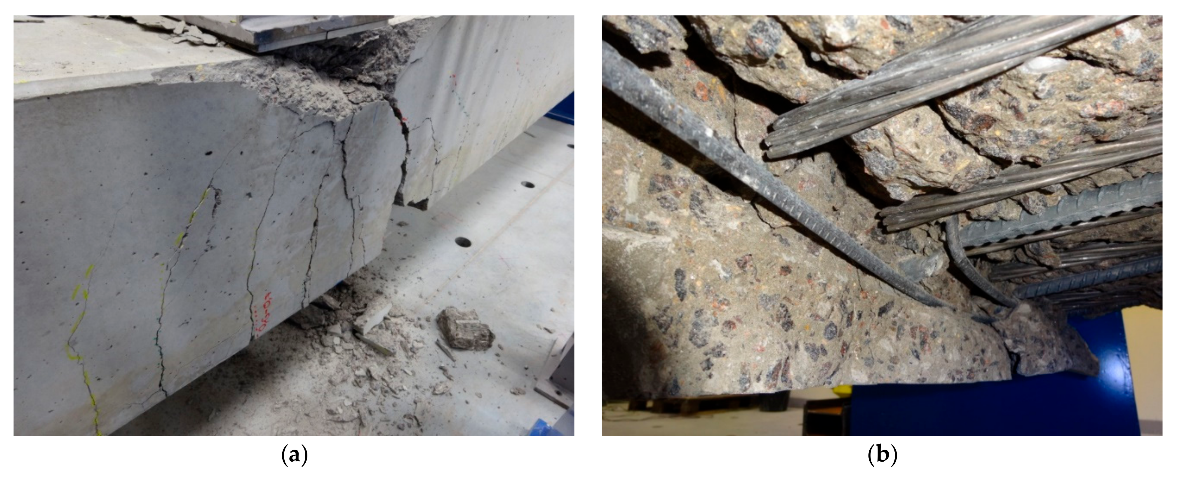
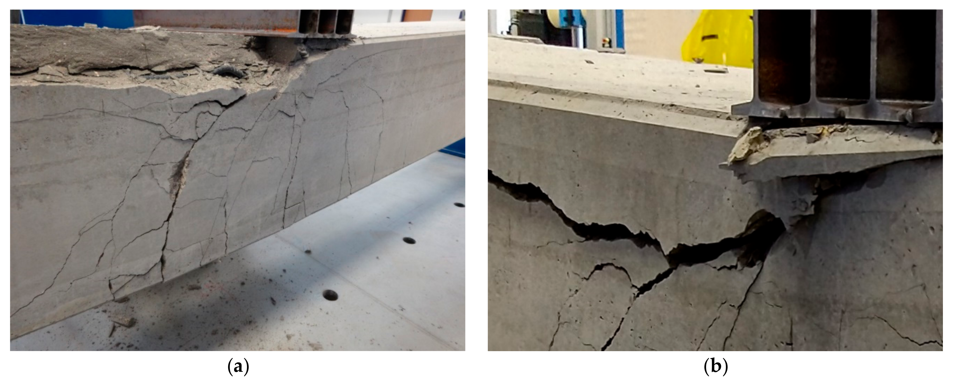
The tested peak load of HPC experimental beams was 1080 kN and 1043 kN. There is about 14% reserve when comparing the mean value of the tested load capacity and the calculated load capacity. The load x mid-span deflection diagram is shown in Figure 9. Yielding of the reinforcement is apparent in the diagram, and rupture of the pretensioned reinforcement was not reached. There was significant damage of the concrete in the compressed part of the cross-section, and in the final stage of testing, the compressed part of the cross-section was detached, Figure 11. Buckling of the compressed non-pretensioned reinforcement emerged. The first visible crack, with a width of 0.05/0.1 mm, appeared for the loading force of about 546 kN. This value is also distinct in the diagram, and, approximately, for this value of the loading force, the linear part of the loading function finishes. The calculated value of the cracking force is 480 kN.
LD diagrams are very similar both for experimental HPC2 beams and the NSC beam. In the initial phase of loading, the LD function is linear. The first visible cracks appeared in the same loading step for the loading force of about 550 kN. As it had been supposed, the first cracks initiated in the mid-span of the tested beam from the bottom surface roughly perpendicular to the lower edge. Under further loading, there was a gradual development of cracks at nearly regular distances from the mid-span to the support area. When reaching the load of approximately 800 kN, the width of the crack increased up to 0.3 mm and the cracks progressed gradually to the upper surface of the beams. The decrease in bending rigidity is significant also in the load x displacement diagram.
A subsequent meaningful decrease in bending rigidity is in the load step of approximately 1000 kN, and the width of some cracks exceeds 1 mm. The increment of the loading force became smaller with the applied deformation. When the peak load was reached, the experimental beams did not collapse to downfall and the beams were gradually unloaded. In the final stage of loading, when testing the NSC beam, the rupture of the pretensioned reinforcement was reached and significant damage of concrete in the compressed part appeared together with buckling of the non-pretensioned reinforcement. In the final stage of testing of the HPC beam, the rupture of the pretensioned reinforcement was not reached; however, when applying the deformation with a nearly zero increment of force, the damaged area under the load-applying steel element was connected with a progressive crack, and this led to the detachment of the compressed upper part of the cross-section.
The load capacity was reached in bending as expected with the yielding of the pretensioned reinforcement. The reserve in the calculated load capacity is 18% for NSC and 14% for HPC. The reserve in the calculated crack load is 22% for NSC and 14% for HPC.
5. Tentative Price and Expenses
5.1. Tentative Price of Materials
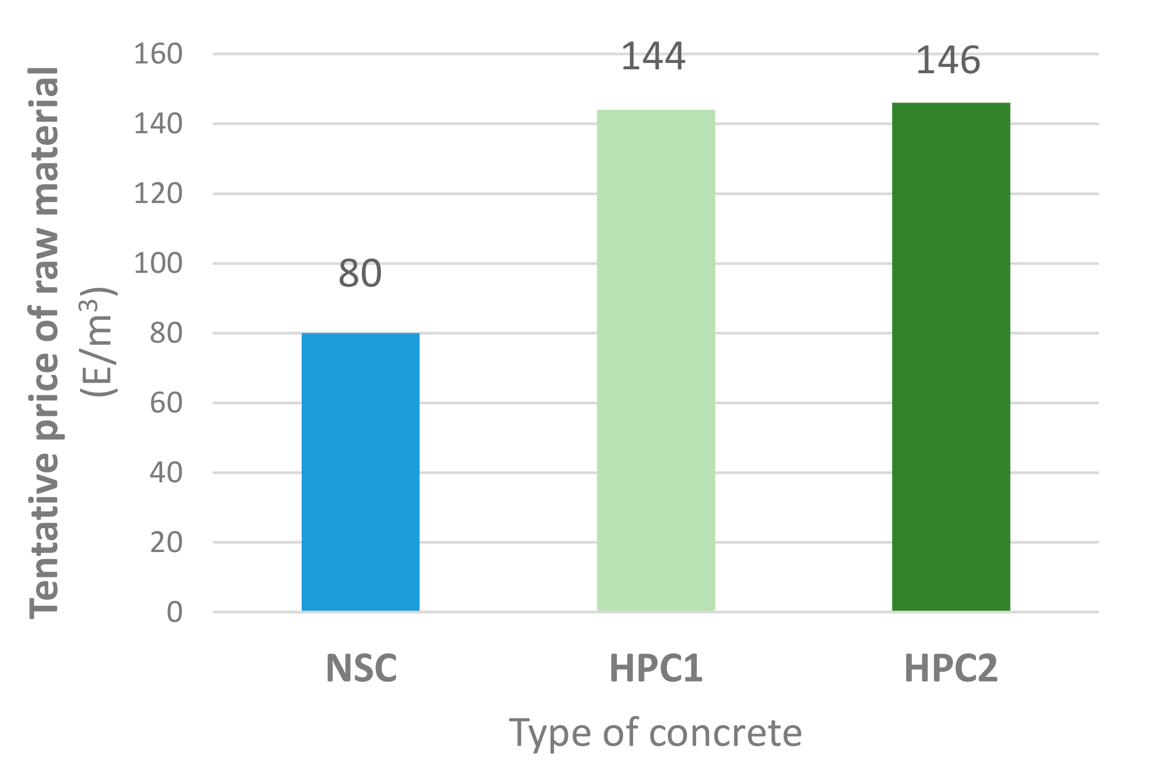
The incorporation of precast load-bearing elements made of HPC in the portfolio of an industrial company is strongly connected with economical aspects. In Figure 12, a graphical comparison of tentative initial expenses on 1 m3 of concrete based on the price of raw materials is shown, according to data provided from the producer. Both variants of HPC are about 1.8 times more expensive than NSC, which corresponds to data from the professional literature, where the price of HPC is about 1.5–2.0 times more expensive than NSC. Prices of reinforcement in parametrical calculations are 0.9 E/m for pretensioned reinforcement, and 0.8 E/kg for non-pretensioned reinforcement.
5.2. Comparison of Testing Slab Beams
In Table 7, the initial expenses for testing slab beams are compared. Consumption of pretensioned and non-pretensioned reinforcements is nearly the same for both types of testing beams. The reduction in concrete consumption is small when retaining the same load and crack capacity. The increase in initial expenses for 1 kN of tested load capacity is 40% for the HPC testing beam compared with the NSC beam. It has to be emphasized that the comparison of expenses is only a basic rough assessment of prices of used materials.
5.3. Study of T- and I-Shaped Beams
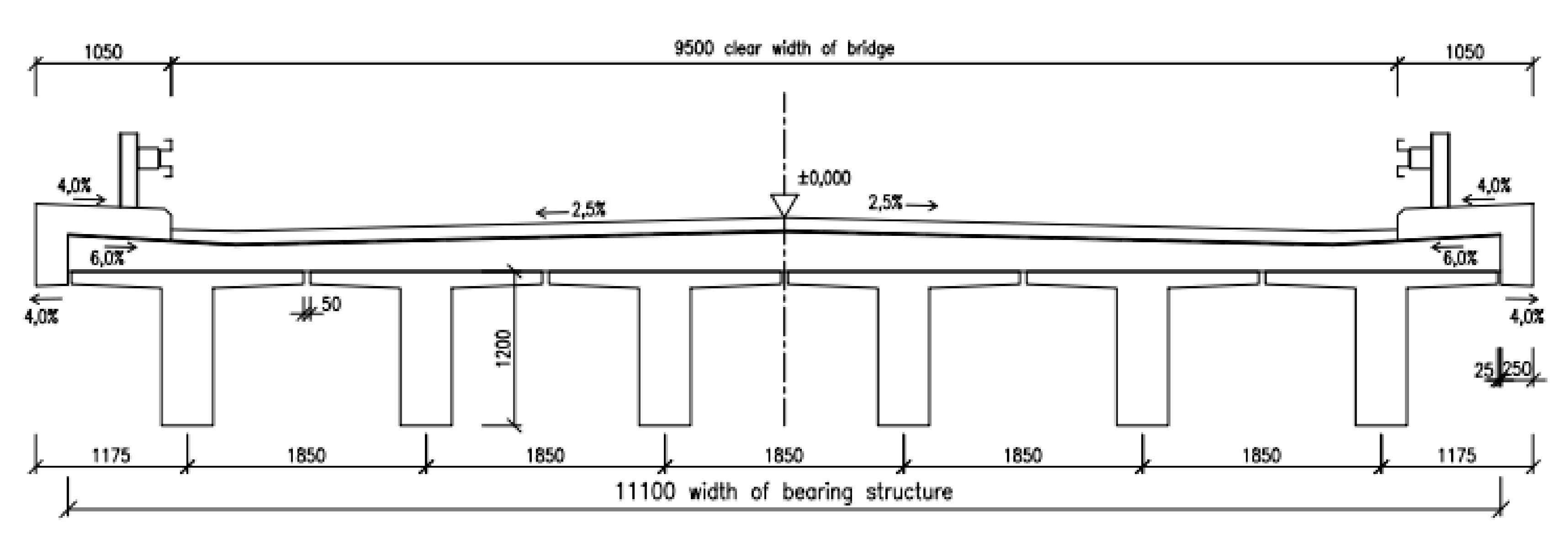
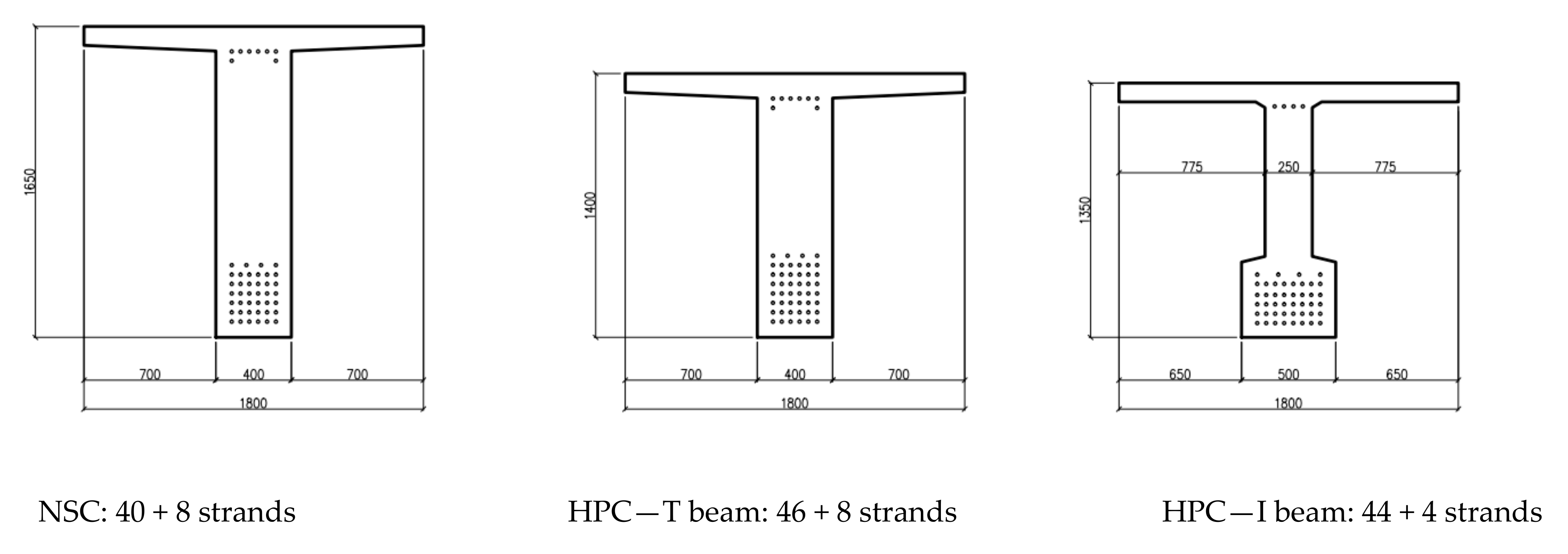
A deeper study of HPC utilization was conducted on a model road bridge made of six beams with a clear width of 9.5 m, Figure 13. The span of the parametric bridge is 15 m, 20 m, 25 m and 30 m. Utilization of the higher compressive strength of HPC enables an increase in the initial prestressing force. In each variant of the used material and span, it is possible to design a few variants of beams. In this study, beams with a minimum height/cross-sectional area are mentioned. In Table 8, heights and cross-sectional areas of T- and I-shaped bridge beams, designed for a parametrical bridge, are stated. The decrease in the cross-sectional area of T beams made of HPC is about 12% compared with NSC. In a slightly optimized variant of the bridge beam with an enlarged bottom flange, the I-shaped beam, the decrease in the cross-sectional area is about 30% compared with the T-shaped NSC beam. In Figure 14, cross-sections of bridge beams for a span of 30 m are compared together with the number of pretensioned strands.
In Table 9, a comparison of raw material expenses for T- and I-shaped parametrical bridge beams made of HPC and NSC is presented. A considerable part of the price is represented by the pretensioned and non-pretensioned reinforcements, and this affects the final expenses balance, which is a 25% increase in expenses for the HPC T-shaped beam and only a 5% increase for the HPC I-shaped beam compared with T beam made of NSC; however, this variant is inconsiderably more laborious due to the more complicated formwork.
It has to be emphasized that the comparison of expenses is only a tentative rough assessment of the prices of the used material without taking into consideration costs concerning the used technology, build-in reinforcement and labor, e.g., due to the more complicated formwork of I-shaped beams. On the other hand, the decrease in structural elements’ weight brings forth savings in transport expenses.
6. Discussion
Extensive material research focused on new compositions of HPC is carried out worldwide, with the aim to increase the strength characteristics together with improvements in other utility properties. The limiting factor of this research is, among other things, the context of laboratory small specimen testing and the industrial conditions of production.
Within the presented research, it was proved that within the optimization of the ordinary concrete composition, it is possible to achieve a compressive strength of about 100 MPa under the industrial conditions of the research partner. HPC was designed with a ternary binder with an increased cement portion, utilization of metakaolin and a superplasticizer and a change in the aggregate size ratio. The subject of different laboratory and industrial conditions is also discussed in [40], where the testing of precast bridge segments is described.
Based on previous testing, the second variant of HPC was preferred. In [41], long-term testing of the fracture energy and toughness of concrete with a lower water–cement ratio is described. A significant decrease in the fracture parameters of specimens made of concrete with an aggregate size of 22 mm was observed after one year, whilst the decrease in concrete with an aggregate size of 16 mm was smaller and no decrease in the fracture parameters was observed in concrete with an aggregate size of 8 mm. Strength characteristics stayed unaffected. The explanation is probably in the autogenous shrinkage of the cement paste and microcracks that arose on the aggregate’s surface. The interfacial transition zone, which is developed especially around the higher-size aggregate, promotes this microcracking.
The HPC concrete mixture brings forth the change in microstructure, the increase in compactness and, consequently, increased durability. The case of bridge structure degradation due to exposure to chloride aerosols is the key factor for material durability and structural life span. Within the tests of the chloride diffusion coefficient, it was proved that the resistance to chloride penetration is about three times higher for both variants of HPC than for NSC.
When designing a new concrete mixture, it is valuable to complement laboratory testing of small specimens with the loading test of structural elements. The three pretensioned elements which were tested within the presented research showed very similar behavior. The positive influence of pretension resulted in a higher cracking load and slow crack development. Failure due to the pretensioned reinforcement yielding enabled high deformability, which was in the final stage of loading in 1/30 of the span. The calculated value of the load-bearing capacity and the value based on testing correspond well both for experimental beams made of NSC and HPC2. The disadvantage of HPC with the compressive strength on the border or outreaching the limits of validity of the current design code is the higher danger of brittle failure. Testing of the load capacity indicates that the ultimate bending moment calculation model reflected the danger of brittle failure in the value of the concrete ultimate limit strain and particular coefficients for the decrease in the compressed cross-sectional area [17,19]. The similar course of the loading test and failure mode allows assuming analogical computational methods both for NSC and HPC beams. An analogical discussion of HPC column design is presented in [42].
Conditions for wider utilization of HPC and UHPC in the precast industry are concisely and objectively discussed in [43]. Locally mixed and produced HPC/UHPC mixtures and optimized structural members are mainly cost-effective for buildings and bridges.
When taking into consideration the price of pretensioned and non-pretensioned reinforcements, the increase in the structural element total price is 40% for HPC in the case of experimental slab beams. However, in a deeper study of a parametrical bridge, it was quantified that HPC T-shaped beams are about 25% more expensive than NSC T beams and in a slightly optimized variation of HPC I-shaped beams, the increase in price is only 5%. Though all complex and hardly quantified relevant expenses are not taken into consideration, the information about the price of used materials is meaningful for primary comparison.
The decrease in the structural element‘s height could be decisive in the case of replacing an insufficient existing structure [8] and also from the perspective of the design value of the water level.
Nevertheless, the expenses should be inspected not only with respect to the manufacturing cost but also in the context of the whole life span, which is, in the case of bridges, 100 years. Convincing quantification of all relevant expenses, together with environmental impact, i.e., life cycle analysis, is the objective of many research tasks [44,45]. Their application in the case of bridge beams is the object of future research.
7. Conclusions
Complex research of HPC was presented which comprises the design of concrete mixtures, testing of mechanical properties of concrete cast in industrial conditions, testing of load capacity of pretensioned experimental beams made of commonly used and newly developed concrete, testing of durability and a tentative primary comparison of expenses.
In the paper, two variants of HPC were presented. Under industrial conditions, a progressive and perspective compressive strength of HPC of about 100 MPa was achieved.
Testing of pretensioned experimental beams indicates the conveniency of the calculation model of the ultimate bending moment capacity for structural elements made of concrete with compressive strength on the border or outreaching the limits of validity of the current design code.
An increase in resistance to chloride penetration of the new HPC variant compared to ordinarily used concrete was proved with AASTO and NORD laboratory testing.
The designed HPC is 1.8 times more expensive than NSC. Nevertheless, the inconsiderable item of the price is the cost of the reinforcement. The tentative raw comparison on parametrical bridge beams indicates that when taking into consideration the total cost, the increase in expenses of HPC bridge beams is acceptable at 25%, which is balanced with increased durability. In the slightly optimized but more laborious variant of the cross-section, the increase in expenses is only 5%.
Application of HPC in the construction industry leads to its further development and, in a wider context, to the construction of economical and sustainable structures with an increased life span.
Author Contributions
V.B., design of concrete mixture; O.S., supervisor of material characteristics tests, supervisor of loading tests of experimental beams in Centre of Building Experiments, VSB-TU Ostrava, evaluation of test results; P.M., design of precast bridge beams, preparing manuscript. All authors have read and agreed to the published version of the manuscript.
Funding
Czech Science Foundation (GACR) and conceptual development of science, research and innovation assigned to VŠB-TUO by the Ministry of Education, Youth and Sports of the Czech Republic.
Acknowledgments
The work was supported by project GACR 21-08772S—Influence of Self-Healing effects on structural fatigue life extension of structures made from high performance concrete (InShe), and The Operational Programme Enterprise and Innovation for Competitiveness (OP EIC), project CZ.01.1.02/0.0/0.0/15_019/0004505 Complex design of beams made of new advanced types of concrete. The work was also supported by means of the conceptual development of science, research and innovation assigned to VŠB-TUO by the Ministry of Education, Youth and Sports of the Czech Republic. The authors would like to appreciate the considerable support of the industrial partners, namely, Cevora, Rudolecka and Andres from divisions in Litice and Orlici.
Conflicts of Interest
The authors declare no conflict of interest.
References
- Aitcin, P.C. High Performance Concrete; CRC Press: Boca Raton, FL, USA, 2018; ISBN 978036786598. [Google Scholar]
- Park, S.; Wu, S.; Liu, Z.; Pyo, S. The Role of Supplementary Cementitious Materials (SCMs) in Ultra High Performance Concrete (UHPC): A Review. Materials 2021, 14, 1472. [Google Scholar] [CrossRef]
- Thomas, M. The effect of supplementary cementing materials on alkali-silica reaction: A review. Cem. Concr. Res. 2011, 41, 1224–1231. [Google Scholar] [CrossRef]
- Long, G.; Gao, Y.; Xie, Y. Designing more sustainable and greener self-compacting concrete. Constr. Build. Mater. 2015, 84, 301–306. [Google Scholar] [CrossRef]
- Chiaia, B.; Fantilli, A.P.; Guerini, A.; Volpatti, G.; Zampini, D. Eco-mechanical index for structural concrete. Constr. Build. Mater. 2014, 67, 386–392. [Google Scholar] [CrossRef]
- Kuruşcu, A.O.; Girgin, Z.C. Efficiency of Structural Materials in Sustainable Design. J. Civ. Eng. Arch. 2014, 8, 8. [Google Scholar] [CrossRef] [Green Version]
- Kioumarsi, M.; Benenato, A.; Ferracuti, B.; Imperatore, S. Residual Flexural Capacity of Corroded Prestressed Reinforced Concrete Beams. Metals 2021, 11, 442. [Google Scholar] [CrossRef]
- Moravcik, M.; Bujnakova, P.; Bahleda, F. Failure and damage of a first-generation precast prestressed bridge in Slovakia. Struct. Concr. 2020, 21, 2353–2362. [Google Scholar] [CrossRef]
- Chu, H.; Wang, F.; Wang, L.; Feng, T.; Wang, D. Mechanical properties and environmental evaluation of ultra-high-performance concrete with aeolian sand. Materials 2020, 13, 3148. [Google Scholar] [CrossRef]
- Vázquez-Rodríguez, F.J.; Elizondo-Villareal, N.; Verástegui, L.H.; Tovar, A.M.A.; López-Perales, J.F.; de León, J.E.C.; Gómez-Rodríguez, C.; Fernández-González, D.; Verdeja, L.F.; García-Quiñonez, L.V.; et al. Effect of Mineral Aggregates and Chemical Admixtures as Internal Curing Agents on the Mechanical Properties and Durability of High-Performance Concrete. Materials 2020, 13, 2090. [Google Scholar] [CrossRef]
- Feo, L.; Ascione, F.; Penna, R.; Lau, D.; Lamberti, M. An experimental investigation on freezing and thawing durability of high performance fiber reinforced concrete (HPFRC). Compos. Struct. 2020, 234, 111673. [Google Scholar] [CrossRef]
- Singh, S.P.; Singh, N. Reviewing the carbonation resistance of concrete. J. Mater. Eng. Struct. 2016, 3, 35–57. [Google Scholar]
- Czarnecki, L.; Woyciechowski, P.; Adamczewski, G. Risk of concrete carbonation with mineral industrial by-products. KSCE J. Civ. Eng. 2017, 22, 755–764. [Google Scholar] [CrossRef]
- Yoon, Y.S.; Kwon, S.J. Evaluation of time-dependent chloride resistance in HPC containing fly ash cured for 1 year. J. Korea Inst. Struct. Maint. Insp. 2018, 22, 52–59. [Google Scholar]
- Li, L.; Zheng, J.; Ng, P.; Zhu, J.; Kwan, A. Cementing efficiencies and synergistic roles of silica fume and nano-silica in sulphate and chloride resistance of concrete. Constr. Build. Mater. 2019, 223, 965–975. [Google Scholar] [CrossRef]
- Bilek, V., Sr.; Bilek, V., Jr.; Krutil, K.; Krutilova, K. Some aspect of durability of concrete with ternary binders. In Proceedings of the 8th CCC Durability of Concrete, Plitvice Lakes, Croatia, 4–6 October 2012; pp. 359–364, ISBN 978-953-7621-14-8. [Google Scholar]
- EN 1992-1-1: Eurocode 2: Design of Concrete Structures—Part 1–1: General Rules and Rules for Buildings; British Standard Institution: London, UK, 2004.
- EN 1992-2: Eurocode 2: Design of Concrete Structures: Part 2: Concrete Bridges; British Standard Institution: London, UK, 2005.
- Cairns, J. Model Code 2010 First Complete Draft; fib Bulletin: Lausanne, Switzerland, 2010; Volume 1, ISBN 978-2-88394-095-6. [Google Scholar]
- Siwiński, J.; Szcześniak, A.; Stolarski, A. Modified Formula for Designing Ultra-High-Performance Concrete with Experimental Verification. Materials 2020, 13, 4518. [Google Scholar] [CrossRef] [PubMed]
- He, Z.-H.; Du, S.-G.; Chen, D. Microstructure of ultra high performance concrete containing lithium slag. J. Hazard. Mater. 2018, 353, 35–43. [Google Scholar] [CrossRef] [PubMed]
- Park, G.-K.; Park, G.-J.; Park, J.-J.; Lee, N.; Kim, S.-W. Residual Tensile Properties and Explosive Spalling of High-Performance Fiber-Reinforced Cementitious Composites Exposed to Thermal Damage. Materials 2021, 14, 1608. [Google Scholar] [CrossRef] [PubMed]
- Li, C.; Feng, Z.; Ke, L.; Pan, R.; Nie, J. Experimental Study on Shear Performance of Cast-In-Place Ultra-High Performance Concrete Structures. Materials 2019, 12, 3254. [Google Scholar] [CrossRef] [Green Version]
- Karimipour, A.; Edalati, M. Shear and flexural performance of low, normal and high-strength concrete beams reinforced with longitudinal SMA, GFRP and steel rebars. Eng. Struct. 2020, 221, 111086. [Google Scholar] [CrossRef]
- Tej, P.; Kolísko, J.; Kněž, P.; Čech, J. The overall research results of prestressed i-beams made of ultra-high performance concrete. In Proceedings of the IOP Conference Series: Materials Science and Engineering, Prague, Czech Republic, 13–16 September 2017; IOP Publishing: Bristol, UK, 2017; Volume 246, p. 12051. [Google Scholar]
- Bilek, V.; Fiala, C.; Hajek, P. High Performance concrete for sustainable building elements and structures, In Proceedings of the 3rd R. N. Raikar Memorial International Conference Gettu-Kodur International Symposium on Advances in Science Technology of Concrete, Mumbai, India, 14–15 December 2018; pp. 213–218, ISBN 978-93-88237-28-4. [Google Scholar]
- Sucharda, O.; Bilek, V.; Mateckova, P. Testing and mechanical properties of high strength concrete. In Proceedings of the IOP Conference Series: Materials Science and Engineering, Zuberec, Slovakia, 29–31 May 2019; IOP Publishing: Bristol, UK, 2019; Volume 549, p. 012012. [Google Scholar]
- CSN EN 12390-3:2020: Testing Hardened Concrete—Part 3: Compressive Strength of Test Specimens; Czech Standardization Agency: Prague, Czech Republic, 2020.
- CSN EN 12390-6:2010: Testing Hardened Concrete—Part 6: Tensile Splitting Strength of Test Specimens; Czech Standardization Agency: Prague, Czech Republic, 2010.
- CSN ISO 1920-10:2016: Testing of Concrete—Part 10: Determination of Static Modulus of Elasticity in Compression; Czech Standardization Agency: Prague, Czech Republic, 2016.
- Seitl, S.; Miarka, P.; Bílek, V. The mixed-mode fracture resistance of C 50/60 and its suitability for use in precast elements as determined by the Brazilian disc test and three-point bending specimens. Theor. Appl. Fract. Mech. 2018, 97, 108–119. [Google Scholar] [CrossRef]
- Miarka, P.; Seitl, S.; Bílek, V. Mixed-mode fracture analysis in high-performance concrete using a Brazilian disc test. Mater. Teh. 2019, 53, 233–238. [Google Scholar] [CrossRef]
- AASHTO TP 95—AASHTO Method of Test for Surface Resistivity Indication of Concrete’s Ability to Resist Chloride Ion Penetration; American Association of State Highway and Transportation Officials: Washington, DC, USA, 2011.
- NT BUILD 443—Concrete, Hardened: Accelerated Chloride Penetration; Nordtest: Espoo, Finland, 1995.
- Tran, Q.; Ghosh, P.; Lehner, P.; Konečný, P. Determination of Time Dependent Diffusion Coefficient Aging Factor of HPC Mixtures. Key Eng. Mater. 2020, 832, 11–20. [Google Scholar] [CrossRef]
- Konečný, P.; Lehner, P.; Ghosh, P.; Morávková, Z.; Tran, Q. Comparison of procedures for the evaluation of time dependent concrete diffusion coefficient model. Constr. Build. Mater. 2020, 258, 119535. [Google Scholar] [CrossRef]
- Lehner, P.; Konečný, P.; Le, D.T.; Bílek, V. Contribution to comparison of methods for the investigation of chloride ingress related resistance. Res. Model. Civ. Eng. 2019, 1, 31–40. [Google Scholar]
- IDEA, Idea Statica [Software]. Available online: https://www.ideastatica.com/concrete (accessed on 10 January 2021).
- Le, T.D.; Konecny, P.; Mateckova, P. Time dependent variation of carrying capacity of prestressed precast beam. IOP Conf. Ser. Earth Environ. Sci. 2018, 143, 012013. [Google Scholar] [CrossRef]
- Vitek, J.L.; Coufal, R.; Čítek, D. UHPC—Development and Testing on Structural Elements. Procedia Eng. 2013, 65, 218–223. [Google Scholar] [CrossRef] [Green Version]
- Bilek, V. Possibility of explanation of interesting development of mechanical characteristics of concrete. In Life Prediction and Aging Management of Concrete Structures; RILEM Publications SARL: Bratislava, Slovakia, 1999; pp. 213–218. [Google Scholar]
- Fiala, C.; Hejl, J.; Tomalová, V.; Bílek, V.; Pavlů, T.; Vlach, T.; Volf, M.; Novotná, M.; Hajek, P. Structural Design and Experimental Verification of Precast Columns from High Performance Concrete. Adv. Mater. Res. 2015, 1106, 110–113. [Google Scholar] [CrossRef]
- Tadros, M.K.; Gee, D.; Asaad, M.; Lawler, J. Ultra-High-Performance Concrete: A Game Changer in the Precast Concrete Industry. PCI J. 2020, 65, 33–36. [Google Scholar] [CrossRef]
- Hrabová, K.; Teplý, B.; Hájek, P. Concrete, Sustainability and Limit States. IOP Conf. Ser. Earth Environ. Sci. 2019, 290, 012049. [Google Scholar] [CrossRef]
- Geiker, M.R.; Michel, A.; Stang, H.; Vikan, H.; Lepech, M.D. Design and maintenance of concrete structures requires both engineering and sustainability limit states. In Proceedings of the 6th International Symposium on Life-Cycle Civil Engineering, Ghent, Belgium, 28–31 October 2018; CRC Press: Boca Raton, FL, USA, 2019; pp. 987–991. [Google Scholar]
Figure 1.
Concrete microstructure: common concrete with water–cement ratio w/c = 0.55 (a), and high-performance concrete, variant 1 with w/c = 0.29 (b).
Figure 1.
Concrete microstructure: common concrete with water–cement ratio w/c = 0.55 (a), and high-performance concrete, variant 1 with w/c = 0.29 (b).

Figure 2.
Comparison of cylinder compressive strength (a) and cylinder/cube compressive strength ratio (b).
Figure 2.
Comparison of cylinder compressive strength (a) and cylinder/cube compressive strength ratio (b).

Figure 3.
Comparison of spit tensile strength (a) and cube compressive strength in 24 h (b).

Figure 4.
Specimens in chloride solution prepared for NT BUILD 443 test (a) and diffusion coefficient testing based on AASHTO TP-95 (b).
Figure 4.
Specimens in chloride solution prepared for NT BUILD 443 test (a) and diffusion coefficient testing based on AASHTO TP-95 (b).

Figure 5.
Comparison of aging factor (a) and diffusion coefficient (b)—NSC and HPC.

Figure 6.
Dimensions of experimental beams’ cross-section, and layout of pretensioned reinforcement: cross-section of NSC beam (a), and cross-section of HPC2 beam (b).
Figure 6.
Dimensions of experimental beams’ cross-section, and layout of pretensioned reinforcement: cross-section of NSC beam (a), and cross-section of HPC2 beam (b).

Figure 7.
Prepared pretensioned and non-pretensioned reinforcements of experimental beams (a), and casting of concrete (b).
Figure 7.
Prepared pretensioned and non-pretensioned reinforcements of experimental beams (a), and casting of concrete (b).

Figure 8.
Three-point loading test in Centre of Building Experiments (a), and spreading of concentrated force with steel element (b).
Figure 8.
Three-point loading test in Centre of Building Experiments (a), and spreading of concentrated force with steel element (b).

Figure 9.
Load–deformation diagram testing of NSC beam compared with testing of HPC beams.

Figure 10.
Failure of NSC beam: crack pattern (a), and rupture of pretensioned reinforcement (b).

Figure 11.
Failure of HPC beam: crack pattern (a), and rupture of the compressed part of the cross-section (b).
Figure 11.
Failure of HPC beam: crack pattern (a), and rupture of the compressed part of the cross-section (b).

Figure 12.
Comparison of tentative raw material price of NSC and variants of HPC.

Figure 13.
Section of model road bridge.

Figure 14.
Cross-section of bridge beams with layout of pretensioned reinforcement, bridge span 30.


Table 1.
Concrete mixture of normal strength concrete (NSC) and high-performance concrete (HPC).
| Raw Material [kg] | NSC Max. Agg. 16 mm | HPC1 Max. Agg. 16 mm | HPC2 Max. Agg. 8 mm |
|---|---|---|---|
| Cement 42.5 | 450 | 575 | 650 |
| Slag | 0 | 40 | 60 |
| Limestone | 0 | 30 | 15 |
| Metakaolin | 0 | 80 | 75 |
| Plasticizer | 4.5 | - | - |
| Superplasticizer | - | 20 | 17 |
| Water | 180 | 165 | 165 |
| Aggregates 0/4 (Lipa nad Orlici) | 690 | 590 | 830 |
| Aggregates 4/8 (Litice nad Orlici) | 215 | 185 | 520 |
| Aggregates 8/16 (Litice nad Orlici) | 845 | 725 | - |
| w/c | 0.40 | 0.29 | 0.25 |
Table 2.
Tested material characteristics.
| NSC | HPC1 | HPC2 | |||||
|---|---|---|---|---|---|---|---|
| Number of Specimens | Mean Value | Standard Deviation | Mean Value | Standard Deviation | Mean Value | Standard Deviation | |
| Cube Compressive Strength [MPa] | 3 | 85.8 | 3.4 | 101.0 | 3.3 | 106.2 | 3.3 |
| Cylinder Compressive Strength [MPa] | 6 | 65.5 | 5.7 | 94.1 | 5.9 | 99.1 | 5.9 |
| Static Modulus of Elasticity [GPa] | 3 | 35.0 | 1.0 | 42.1 | 3.8 | 41.2 | 4.3 |
| Split Tensile Strength [MPa] | 6+3 | 5.9 | 0.3 | 5.9 | 0.4 | 6.4 | 0.3 |
Table 3.
Diffusion coefficient and aging factor—NSC.
| Time | [Days] | 7 | 14 | 28 | 56 | 91 | 161 |
|---|---|---|---|---|---|---|---|
| Diffusion Coefficient | [m2/s] | 1.3 × 10⁻¹¹ | 9.6 × 10⁻¹² | 8.79 × 10⁻¹² | 6.01 × 10⁻¹² | 5.93 × 10⁻¹² | 5.89 × 10⁻¹² |
| Aging Factor m (AASHTO TP-95) | [–] | 0.2884 | |||||
| Diffusion Coefficient (Nord 443) | [m2/s] | 10.1 × 10⁻¹² | |||||
Table 4.
Diffusion coefficient and aging factor—HPC1.
| Time | [Days] | 7 | 14 | 28 | 56 | 91 | 161 |
|---|---|---|---|---|---|---|---|
| Diffusion Coefficient | [m2/s] | 4.66 × 10⁻¹² | 3.88 × 10⁻¹² | 2.59 × 10⁻¹² | 1.97 × 10⁻¹² | 1.62 × 10⁻¹² | 1.24 × 10⁻¹² |
| Aging Factor m (AASHTO TP-95) | [–] | 0.4197 | |||||
| Diffusion Coefficient (Nord 443) | [m2/s] | 3.46 × 10⁻¹² | |||||
Table 5.
Diffusion coefficient and aging factor—HPC2.
| Time | [Days] | 7 | 14 | 28 | 56 | 91 | 161 |
|---|---|---|---|---|---|---|---|
| Diffusion coefficient | [m2/s] | 3.62 × 10⁻¹² | 2.93 × 10⁻¹² | 2.54 × 10⁻¹² | 2.04 × 10⁻¹² | 1.73 × 10⁻¹² | 1.51 × 10⁻¹² |
| Aging Factor m (AASHTO TP-95) | [–] | 0.2777 | |||||
| Diffusion Coefficient (Nord 443) | [m2/s] | 3.72 × 10⁻¹² | |||||
Table 6.
Load capacity of specimen beams.
| NSC | HPC2 | |||
|---|---|---|---|---|
| Load Capacity | Crack Capacity | Load Capacity | Crack Capacity | |
| Calculation—bending moment capacity [kNm] | 1643 | 781 | 1581 | 779 |
| Calculation—ultimate load [kN] | 970 | 480 | 935 | 479 |
| Experiment—peak load [kN] | 1148 | 586 | 1062 | 546 |
Table 7.
Tentative expenses of testing beams.
| NSC Testing Beam | HPC Testing Beam | ||||
|---|---|---|---|---|---|
| Amount | Price [E] | Amount | Price [E] | ||
| Concrete | 3.53 m3 | 283 | 3.28 m3 | 479 | |
| Pretensioned reinforcement | 144 m | 130 | 144 m | 130 | |
| Non-pretensioned reinforcement | 190 kg | 152 | 185 kg | 148 | |
| Total price | 565 | 757 | |||
| Expenses for 1 kN of tested load capacity | 0.50 | 0.7 | |||
Table 8.
Height of T beams designed for the study bridge.
| T Beam—NSC | T Beam—HPC | I Beam—HPC | ||||
|---|---|---|---|---|---|---|
| Span [m] | Height [mm] | Area [m2] | Height [mm] | Area [m2] | Height [mm] | Area [m2] |
| 15 | 900 | 0.509 | 750 | 0.449 | ||
| 20 | 1150 | 0.629 | 950 | 0.529 | 850 | 0.431 |
| 25 | 1400 | 0.709 | 1200 | 0.629 | ||
| 30 | 1650 | 0.809 | 1450 | 0.729 | 1350 | 0.583 |
Table 9.
Tentative expenses for parametrical bridge beams.
| NSC—T Beam | HPC—T Beam | HPC—I Beam | |||||
|---|---|---|---|---|---|---|---|
| Span [m] | Amount | Expenses [E] | Amount | Expenses [E] | Amount | Expenses [E] | |
| 20 | Concrete [m3] | 13.2 | 1056 | 11.1 | 1622 | 9.1 | 1322 |
| Pretens. st. [m] | 702 | 632 | 936 | 843 | 820 | 738 | |
| Non-preten. st. [kg] | 974 | 779 | 780 | 624 | 694 | 555 | |
| Total | 2467 | 3089 | 2615 | ||||
| 30 | Concrete [m3] | 25.1 | 2006 | 22.6 | 3300 | 18.1 | 2639 |
| Pretens. st. [m] | 1636 | 1472 | 1840 | 1656 | 1636 | 1472 | |
| Non-preten. st. [kg] | 2147 | 1717 | 1843 | 1475 | 1653 | 1323 | |
| Total | 5195 | 6431 | 5434 | ||||
Publisher’s Note: MDPI stays neutral with regard to jurisdictional claims in published maps and institutional affiliations. |
© 2021 by the authors. Licensee MDPI, Basel, Switzerland. This article is an open access article distributed under the terms and conditions of the Creative Commons Attribution (CC BY) license (https://creativecommons.org/licenses/by/4.0/).
Share and Cite
MDPI and ACS Style
Mateckova, P.; Bilek, V.; Sucharda, O. Comparative Study of High-Performance Concrete Characteristics and Loading Test of Pretensioned Experimental Beams. Crystals 2021, 11, 427. https://0-doi-org.brum.beds.ac.uk/10.3390/cryst11040427
AMA Style
Mateckova P, Bilek V, Sucharda O. Comparative Study of High-Performance Concrete Characteristics and Loading Test of Pretensioned Experimental Beams. Crystals. 2021; 11(4):427. https://0-doi-org.brum.beds.ac.uk/10.3390/cryst11040427
Chicago/Turabian StyleMateckova, Pavlina, Vlastimil Bilek, and Oldrich Sucharda. 2021. "Comparative Study of High-Performance Concrete Characteristics and Loading Test of Pretensioned Experimental Beams" Crystals 11, no. 4: 427. https://0-doi-org.brum.beds.ac.uk/10.3390/cryst11040427
Note that from the first issue of 2016, this journal uses article numbers instead of page numbers. See further details here.