
Toward Commercialization of Stable Devices: An Overview on Encapsulation of Hybrid Organic-Inorganic Perovskite Solar Cells


1
Institute for Photovoltaics (IPV), University of Stuttgart, 70569 Stuttgart, Germany
2
IEK-5 Photovoltaics, Forschungzentrum Jülich, 52425 Jülich, Germany
3
Multifunctional Optical Materials Group, Institute of Materials Science of Sevilla, Consejo Superior de Investigaciones Científicas—Universidad de Sevilla (CSIC-US), Américo Vespucio 49, 41092 Sevilla, Spain
4
BCMaterials—Basque Center for Materials Applications and Nanostructures, UPV/EHU Science Park, Barrio Sarriena s/n, 48940 Leioa, Spain
*
Author to whom correspondence should be addressed.
Crystals 2021, 11(5), 519; https://0-doi-org.brum.beds.ac.uk/10.3390/cryst11050519
Submission received: 14 April 2021
/
Revised: 29 April 2021
/
Accepted: 2 May 2021
/
Published: 7 May 2021
(This article belongs to the Special Issue Interface Engineering for Efficient and Stable Perovskite Based Solar Cells)
Abstract
:Perovskite solar cells (PSCs) represent a promising technology for energy harvesting due to high power conversion efficiencies up to 26%, easy manufacturing, and convenient deposition techniques, leading to added advantages over other contemporary competitors. In order to promote this technology toward commercialization though, stability issues need to be addressed. Lately, many researchers have explored several techniques to improve the stability of the environmentally-sensitive perovskite solar devices. Challenges posed by environmental factors like moisture, oxygen, temperature, and UV-light exposure, could be overcome by device encapsulation. This review focuses the attention on the different materials, methods, and requirements for suitable encapsulated perovskite solar cells. A depth analysis on the current stability tests is also included, since accurate and reliable testing conditions are needed in order to reduce mismatching involved in reporting the efficiencies of PSC.
1. Introduction
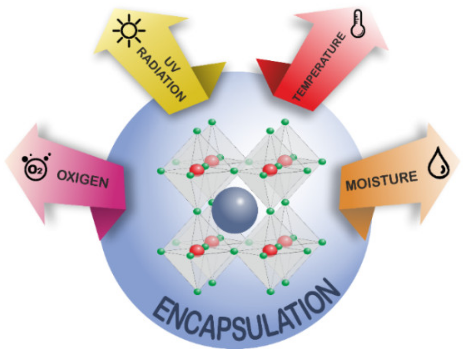
Perovskite Solar Cells (PSCs) have demonstrated outstanding performance, achieving power conversion efficiencies (PCE) as high as 25.5% and theoretical efficiencies up to 31%. Since the inception of PSCs in 2009 [1], a lot of improvements have been done in various aspects, like composition [2], synthesis technique, fabrication method [3], and interfacial studies [4]. In addition, an even higher PCE can be obtained by combining the two silicon and PSC devices together, i.e., perovskite/silicon tandem solar cells, by exceeding the Shockley–Queisser limit [5]. Unfortunately, it is challenging to obtain satisfactory lifetime during PSC operation when compared to that of silicon solar cells. In fact, unlike the silicon solar cells, the instability of hybrid organic-inorganic PSC devices remains a significant bottleneck to commercialization [6]. Currently, PSCs are only stable up to few months at an outdoor environment [7,8], since PSCs are sensitive to harsh environmental conditions (see Figure 1) such as UV light exposure [9], high temperature [10,11], and, most importantly, oxygen [12] and humidity [13,14]. In the last few years, different approaches have been explored in order to overcome the mentioned issues. A comprehensive understanding of these issues in PSCs is required to achieve stability breakthroughs for practical commercial applications.
Sources of Degradation of Perovskite Devices
Snaith and co-workers studied the stability of PSCs under UV radiation for the first time [15], demonstrating that perovskite solar cells with TiO2 as photoanode suffered from a rapid decay in photocurrent and power conversion efficiency after encapsulation in a nitrogen atmosphere. The authors showed how an electron–hole pair is formed on TiO2 and the hole in the valence band combines with the electron at the oxygen adsorption site after UV illumination. This might be overcome by introduction of small amount of oxygen, which could decrease the number of empty deep trap sites [15,16]. Another solution to UV degradation of the TiO2 layer was introduced by Komarala and co-workers [17]. The authors proposed that the deposition of a down-shifting (DS) YVO4:Eu3+ nano-phosphor layer on the reverse side of fluorine doped tin oxide (FTO) glass could improve the PSC stability. In fact, the phosphor layer can absorb UV light and emit visible light, which could be absorbed by the underlying perovskite layer. The device showed an improvement in stability under prolonged illumination, retaining more than 50% of its initial efficiency, whereas for PSCs without the phosphor layer, the efficiency diminished to 35% of its initial value [16,17].
On the other hand, temperature enhancement under continuous sun illumination can produce phase changing and instability in the perovskite layer [18]. Connings et al., studied the thermal stability of ITO/TiO2/perovskite set up at 85 °C in order to focus on the absorber layer of the PSCs [19]. Results revealed a high amount of deterioration in the ambient environment than in the presence of nitrogen and oxygen. Pisoni and co-workers showed that MAPI (CH3NH3PbI3) had a very low thermal conductivity for both large single crystals and the polycrystalline form. This meant that the light-deposited heat inside the perovskite itself could not spread out quickly, which caused mechanical stress and limited the lifetime of the photovoltaic devices [20]. Also, studies conducted by Pister et al., stressed the fact that the annealing temperature of MAPI film is important for both thermal stability and efficiency of PSCs, with an ideal temperature range to carry out annealing of MAPb(I/Cl) perovskite between 100 and 150 °C [21].
Furthermore, oxygen represents a crucial environmental parameter related to PSC stability, both during perovskite film preparation and subsequent device exposure. Haque and co-workers showed that photodegradation reaction of MAPI film is triggered by the action of active oxygen species (superoxide O2−) on the organic component (i.e., methylammonium) of the perovskite absorber layer [22]. Lately, also Maier and co-workers demonstrated that since MAPI shows a certain oxygen solubility, and that O2, once introduced, acts as an acceptor dopant owing to O2− replacing I− or being accommodated interstitially. Under these conditions, MAPI is thermodynamically expected to degrade, forming water and iodine [12]. On the other hand, it has been proved that oxygen passivation could enhance the photoluminescence (PL) intensity of the perovskite due to the decrease of the non-radiative recombination.
Lately, it has also been demonstrated that if perovskite layer is exposed to oxygen by exclusion of light illumination, the halide vacancies could be passivated by oxygen atoms, meanwhile, the reaction between oxygen molecule and photogenerated electrons might be prevented, which will lead to the improvement of both efficiency and stability for PSCs [23,24].
Apart of the degradation sources cited above, it is now well established that PSCs are very susceptible to high humidity. The degradation is notably quicker under high humidity conditions, as demonstrated by Zhu et al. [25] by performing stability tests under constant illumination over a short time period in an N2 glovebox to prevent the intrusion of humidity. In order to get over the above-cited problems, many solutions have been addressed in order to improve the stability. For instance, compositional tuning of perovskite materials has been well explored over recent years. For example, it has been demonstrated that the incorporation of different organic and inorganic cations (like cesium, formamidinium, and rubidium) in the structure is beneficial to internal perovskite stability [2,26]. However, phase segregation due to temperature changes can induce instabilities inside the perovskite structure depending on the composition. Table 1 summarizes the phase stability of common perovskite compounds.
Also, the addition of additives in both perovskites, or the charge selective layers, was largely investigated. For instance, the use of hydrophobic ionic liquid have been proved to be effective in order to both enhance device stability and efficiency [38]. Besides all, encapsulation of this PSC device is one of the top priorities to improve and maintain its stability.
Encapsulation needs to ensure long term reliability and increase the production yield with the lowest cost. Since PV modules work in any type of outdoor environments, they can be susceptible to environmental conditions that could lead to degradation, which then negatively affect the performance and lifetime of the device. Furthermore, maintaining the solar cell’s flexibility and transparency become an additional challenge to maximize the solar cell performance. Even if nowadays most PSCs are fabricated on rigid glass substrates, it has to be considered that next generation encapsulation method should also be compatible with roll-to-roll (R2R) processing, which can manufacture thin-film PSC modules at large scale and make solar electricity economically competitive with conventional electricity generation. Front sheets and back sheets are the most exposed parts among any other parts that constitute PSCs.
Different types of filler materials are added as additives for both encapsulants and edge seals specifically designed for PSC module applications. Also, it is important to understand the interfacial chemistry as moisture penetrates through the interfacial regions between the adhesive materials (encapsulants and edge seals) and front sheets and back sheets.
For all the reasons listed above, it is important to have a comprehensive knowledge of the encapsulant chemistry in order to understand the moisture, thermal, and UV stability of the packaging materials for PSCs. The following section reviews the effective strategies to measure and prevent the thermal, chemical, and environmental stability of perovskite-based devices, which serves as useful guideline to future research to fabricate PSCs to meet commercial demands.
2. Stability
Unlike silicon solar cells, the outdoor lifetime of perovskite solar cells is influenced by the varying weather conditions at different geographic locations. Therefore, in order to fulfil the minimum requirements, inter-laboratory collaborations are paramount to determine the viability of this technology at industrial scale.
Presently, passing the IEC 61215:2016, which lays down requirements for the design qualification and type approval of terrestrial photovoltaic modules suitable for long-term operation in general open-air climates, is necessary for the commercialization of any solar device. Because perovskite solar cells are 500 times thinner than silicon cells, they could be used as a coating on other solar cell technology (e.g., silicon tandem cells) as well as other energy harvesting options where the exposure to harsh conditions are avoided, such as building-integrated photovoltaics or indoor applications.
In this context, instabilities provoked by external conditions such as high temperature and high humidity (>85%RH), tend to induce a collapse of the crystal structure, following the proposed degradation reactions (Table 2). In addition, under prolonged light exposure, perovskite solar cells suffer from ion migration, entangling high hysteresis, and high recombination processes. Therefore, specific standard tests are needed such as longer light exposure times.
Currently, to certify a third generation of solar cells, samples were kept at room temperature of 25 ± 2 °C. The current density-voltage j-V curve is measured under light with 1000 ± 100 W·m−2 in accordance with IEC 60904-1:2020; that describes procedures for the measurement of current-voltage characteristics (I-V curves) of photovoltaic (PV) devices in natural or simulated sunlight. Nevertheless, a more specific norm, IEC TR 63228:2019, summarizes current perspectives on the performance evaluation of emerging PV technologies, specifically OPV, DSC, and PSC devices.
In particular, to untangle undesired underlying recombination processes, perovskite devices should be measured under real working conditions at maximum power point (MPP) for at least 100 h to account for the different ionic movements, slow and fast, in the perovskite and also a deep study of the device in dark conditions to check possible current leakages.
According to IEC 61215:2016, samples should pass a series of test depending on the external inputs, temperature, humidity or UV-exposure. Specifically, the norm is divided in sequences and each sequence contains several stress tests aiming specifically for one of the identified main degradation causes that frequently occurs.
- Sequence A, the control sequence, contains mild conditions to provide basic characterisation.
- Sequence B tests hot-spots and outdoor behaviour.
- Sequence C combines several stress tests where the modules are first preconditioned with UV light and then subjected to 50 thermal and 10 humidity freeze cycles.
- Sequence D contains 200 thermal cycles.
- Sequence E is the damp-heat test together with the mechanical stability tests (hail test and mechanical load test).
Although several studies have determined the stability of perovskite solar cells under certain conditions, the combination of some of them will entail the degradation of the perovskite layer and therefore the loss of the opto-electronic properties. In addition, some studies suggest the importance of investigating how perovskite solar cells behave under mechanical load. It is highly unlikely that a solar cell will be commercialized, which degrades or breaks under mechanical load.
In recent years, several effort have been invested in the development of encapsulation procedures compatible with the stability of perovskite material [41,42]. It is well known the high sensitivity to light, high temperature and polar solvents which limits the used of well-stablished sealants (e.g., based on PIB, polyurethane, silicone, and MS polymer technologies, as well as acrylic and butyl tapes). It has been demonstrated [43] that solar cells encapsulated with a stiffer ionomer, such as Surlyn60® or SentryGlas® Plus (SGP), severely decreased in performance, mainly due to the heating of the cell at the curing temperature (100 °C) of the thermoplastic sealant as well as delamination after temperature cycling, which facilitates the inclusion of water molecules. However, the solar cells encapsulated in softer polymers withstood temperature cycling and retained above 85% of their initial performance after several temperature cycles. Nevertheless, due to intrinsic instabilities, a careful and complicated encapsulation system, developed by employing the combination of a desiccant material and UV epoxy resin, exhibited significantly improved stability [44,45,46].
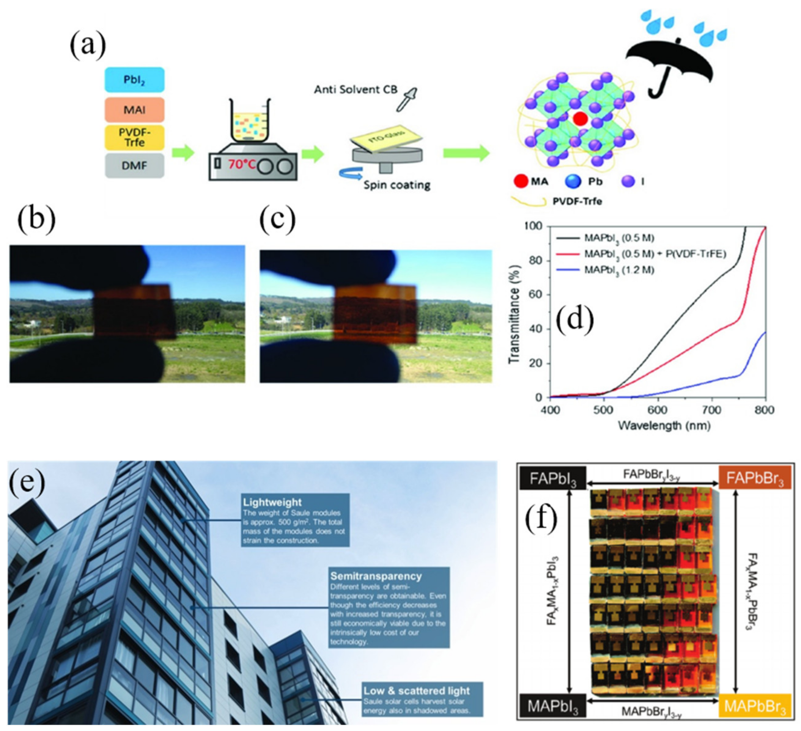
Bearing all this in mind, the possibility of using perovskite solar cells in façade and indoor applications becoming a short-term objective is quite feasible. In the context of smart windows, the bandgap tuneability of perovskite material brings the possibility to easily synthesized perovskite film with different colors. Jacobson et al. [47] published a seminal work focused on the chemical management of MAPb(I1−xBrx)3 perovskites layer. The authors successfully tuned the onset absorption band of the perovskites from 786 nm (1.58 eV) to 544 nm (2.28 eV) by tuning the Br content (Figure 2f).
Besides its bandgap tunability, perovskite solar cells are attention-grabbing due to their high efficiency and excellent transparency. For example, semi-transparent solar cells can be synthesized by the incorporation of polyvinylidene fluoride−trifluoro ethylene polymer, P(VDFTrFE), as an additive to control the crystal formation of the low concentration perovskite solution. This approach improves the coverage as well as increases the crystal size, reducing the grain boundaries of the deposited visible-light-semi-transparent perovskite films through one-step method (Figure 2a–d).
As a real application example (Figure 2e), Saule Technologies [49] installed a cutting-edge perovskite solar panel on the Spark’s office building’s façade in Warsaw, which demonstrates that perovskite technology has potential benefits such as lower energy costs that lead to lower carbon footprints. However, current perovskite-based BIPVs mainly employ lead-based components owing to their ability to deliver high PV performances. Considering their toxicity, it is important to develop lead-free perovskites that can exhibit high PV performance, excellent stability, and low costs [50]. Very recently, Yang et al. [51] improved considerably the stability of tin based perovskite by the addition of a natural phenol and antioxidant (Catechin) into the perovskite layer to suppress oxidation of Sn2+ to Sn4+. In addition, when sample were irradiated by indoor lighting (1000 lx), they exhibited a maximum PCE approaching 12.81%, paving the way for indoor and lead-free photovoltaics.
The main reason of this PCE improvement when compared with other technologies is the following. Crystalline silicon or GaAs-based solar cells absorb in the red region of the visible light and at near-infrared wavelengths, which makes them suitable for outdoor photovoltaics. On the other hand, 3rd generation photovoltaics (organic photovoltaics (OPV), dye sensitized solar cells (DSSC) and perovskite solar cells (PSC)), behave efficiently in the visible range between 400 and 650 nm, which correspond to the largest part of indoor illumination spectra (originating from fluorescent lamps, LEDs and light passing through the windows). However, the location of the PV cell in the room, its orientation, indoor obstacles, etc., can all influence the performance. Therefore, new configuration should be studied in order to boost the devices’ performance under indoor lighting. In this context, Jagadamma et al. [52] fabricated highly efficient indoor perovskite-based devices (PCE 23%) using p-i-n structure, being the hole selective layer a very thin layer of NiO (~6 nm). The authors suggested that the low recombination rate and fast extraction of photogenerated carriers by NiO is particularly suitable for low intensity indoor illumination. In addition, the low process temperature (100 °C) mainly due to the annealing process of the perovskite layer, make them also suitable for flexible devices.
One step forward is presented by Castro-Hermosa et al. [53] where developed perovskite solar cells are put on ultra-thin flexible glass (FGPSCs) for highly efficient indoor energy harvesting. Th authors also compared the power conversion efficiency with different light illumination, obtaining 14.4, 20, and 22% at 100 klx (1 sun), and under artificial white LED indoor illumination 200 and 400 lx illuminance, respectively.
Considering the rapid improvements on both efficiency and stability and considering that a theoretical maximum efficiency of up to 52% has been predicted under 1000 lx cool white LEDs with a bandgap ~1.9 eV, it is expected that these emerging PV technologies can be considered a commercially viable product for use in a broad range of indoor PV applications in the near future [54].
3. Up-Scaling Encapsulation Techniques
Towards the industrialization of perovskite solar cells (PSCs), encapsulation coatings should act as a barrier for the degradation factors affecting their long-term stability during real environmental working conditions. The cathode interface and the active layer are the main targets to protect against the deterioration caused by the extrinsic factors as UV-light, temperature, oxygen, and moisture [55,56]. On the other hand, bulk and interfacial engineering can be developed to reduce the intrinsic weaknesses of perovskite material itself, preventing issues related with Pb leakage [57,58]. An inherently more stable crystal structure, together with an increased robustness of the selective contacts, can also be addressed from the encapsulation point of view [59,60,61]. For this purpose, the selection of the encapsulation material and its technological application are subjected to certain requirements that cannot be overlooked (Table 3). Regarding the material characteristics, the oxygen transmission rate (OTR) and the water vapor transmission rate (WVTR) are the main parameters to evaluate. To guarantee low values of the absorptivity and permeability of both environmental factors, these two parameters need to be placed between the limits of 10−4–10−6 cm3·m−2·d−1·atm−1 and 10−3–10−6 g·m−2·d−1, respectively [62,63]. In addition, the material selected should also be able to absorb fluctuation in strain energy, avoiding mechanical damage during stability tests [64]. To this regard, organic materials, when compared to their inorganic counterparts, present higher versatility due to the tunable synthesis of the organic molecules by varying their energy levels, molecular weight, and solubility [65]. In addition, they show minor impact on the environment being as well as being more disposable [66]. Glass transition temperature (Tg) of the selected material should also be known in terms of the maximum possible exposure temperature and its effect on its mechanical behavior. The light transmission through the encapsulation materials should not affect the device performance. The material also needs to present a high resistance to UV and thermal oxidation, coupled with a high adhesion to the perovskite module to prevent delamination processes during stability tests and operation conditions [56,67].
The technological approaches should also match with several necessities in terms of stability and large-scale suitability. During the encapsulation process, photochemical and thermal damage to the PSCs must be avoided, as well as water and oxygen penetration through the device sides. The coating should have hermetic characteristics, which can be categorized in two main groups: gross and fine leaks, regarding the size of the leak’s channels for oxygen and moisture entering. Values above 10−5 atm·cm3·s−1 are considered as gross leaks, while fine leaks can be divided into: (a) non-hermetic: between 10−5–10−7 atm·cm3·s−1 and (b) hermetic: below 10−7 atm·cm3·s−1 [68,69]. In this regard, blanket encapsulation patterns have been reported as the best option to create a pressure-tight environment, avoiding moisture entering and preventing as well the leakage of any volatile materials from the perovskite device. In fact, this technological approach unifies the functionalities of the two representative packaging systems: top encapsulant barriers and edge sealing [70,71]. The top encapsulant barrier consists of a thin protective layer deposited on top of the module and the edge sealant is placed around the device, bonded to a cover substrate to delay moisture ingress.
To check the reliability of the requirements above mentioned, the standard testing stablished by the International Electrotechnical Commission (IEC) and the International Summit on Organic Photovoltaic Stability (ISOS) (IEC 61215 norm and ISOS protocol) need to be performed, as explained in detail in the previous section [29].
In the following, glass-to-glass, polymer, and thin-film encapsulation, as the three main encapsulation strategies, are summarized remarking in each of them the most suitable and efficient techniques developed for large-scale perovskite solar cell production.
3.1. Glass-to-Glass Encapsulation
Glass-to-glass encapsulation consists in inserting the solar device between two glass sheets. Originally from silicon technology, this strategy allows to retain 95% of the power conversion efficiency of silicon solar cells after 20 years [72]. Currently, it is also one of the most extensively used strategies to improve the long-term stability of perovskite devices. However, this process requires high temperatures to be performed (≥100 °C), which increase the challenge to make this encapsulation process fully compatible with temperature-sensitive PSCs. To this regard, several thermo-curable or UV-curable sealants for the top encapsulant barrier have been developed (e.g., ethylene vinyl acetate (EVA), Surlyn ionomer, butyl rubber, and polyisobutylene (PIB), Ossila E132 resin, epoxy resin or epoxy glue) [45,70,71,73,74] and also different edge sealants like butyl rubber, PIB, or UV epoxy adhesives [75].
In Figure 3 are presented three of the most advanced and effective glass-to-glass methods to ensure most of the requirements be scalable and fully compatible with a wide range of perovskite materials.
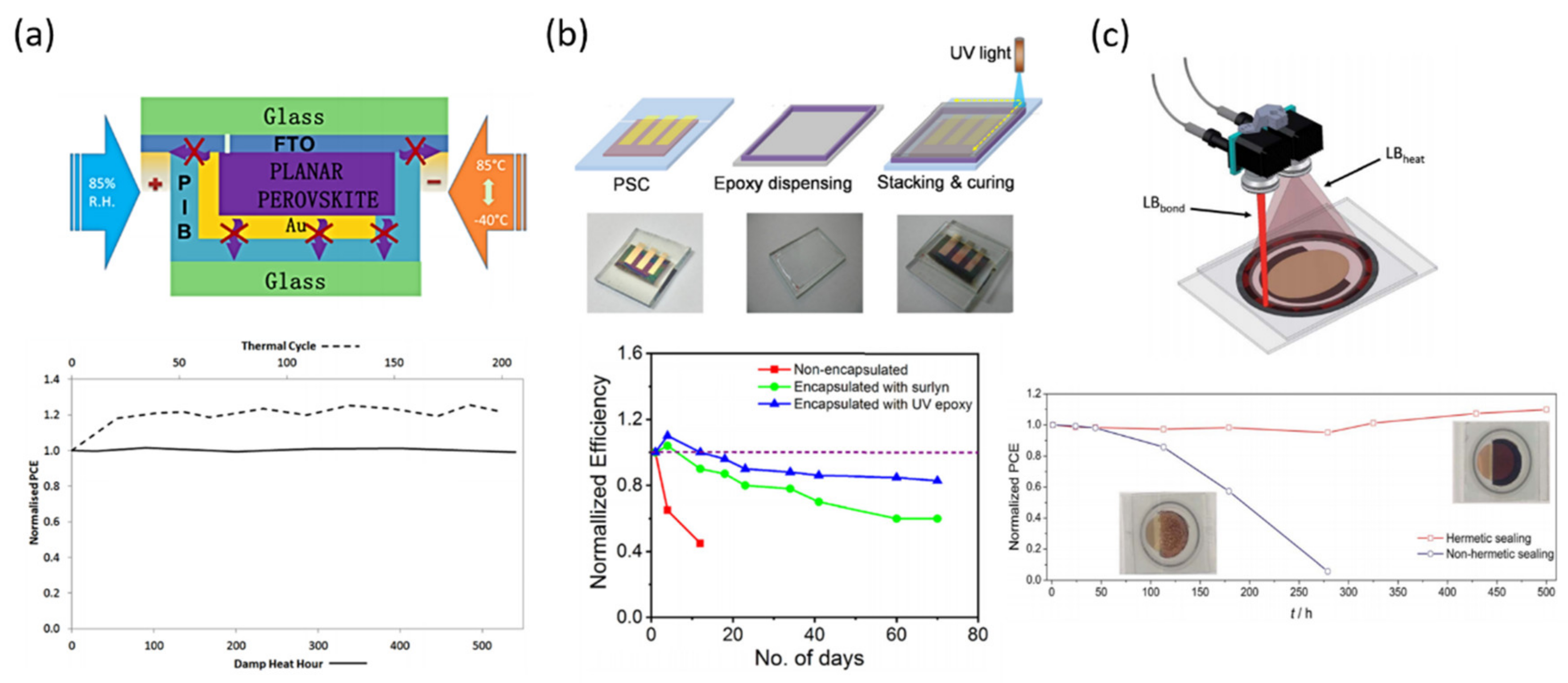
Anita W. Y. Ho-Baillie and co-workers developed a glass-to-glass encapsulation technique using high performance polyisobutylene (PIB) as either an edge seal or blanket layer employing low temperature (Figure 3a) [45]. The PIB material is already used in the Cooper Indium Gallium Selenide (CIGS) thin films modules, but here the effectiveness of the glass-PIB-glass encapsulation was investigated on planar glass/FTO/TiO2/FAPbI3/PTAA/Au perovskite solar cells; comparing as well with the usual EVA and UV-cured epoxy materials. The PIB material was acquired as a tape, so the adaptation to the device dimensions was very simple. They directly cut the PIB and placed, covering the glass to finally protect the PSC. To avoid bubbles and ensure a good bonding, the complete structure was hot-pressed in a solar module laminator.
The complete encapsulated device was tested according to IEC61215:2016; performing two accelerated life time tests, damp heat (DH) and thermal cycling (TC). Compared with EVA or UV-cured epoxy, PIB seems to be inert in terms of reactivity with perovskite device. The average PCE before and after the encapsulation (thermal annealing) maintain similar values, but important phenomenon occurred: the performance during the reverse scan (from VOC to Jsc) decreases while increasing during the forward scan (from Jsc to VOC), leading to a reduced hysteresis index. The appearance of this phenomenon is already known as inverted hysteresis (IH) and has been recently related with an activated process due to ionic diffusion [77]. Even so, the method proposed here shows easy application, sustainability for up-scaling and it can be performed at low temperature, which is critical to avoid perovskite thermal decomposition, and under minimal cost.
The second glass-to-glass method, showed in Figure 3b, uses as well a low temperature encapsulation process, but employing a UV-curable epoxy as edge sealant [75]. In this work, the authors described how the UV irradiation induces the crosslinking of the epoxy, leading to maintain 85% of the original PCE of a free-HTL MAPbI3 perovskite device, using TiO2 as ESL. The effectiveness of the UV-curable epoxy resin lies in the prevention of moisture ingress, enhancing the device stability proved during 70 days. However, the stability tests performed here do not correspond with the current requirements, being performed just aging the PSC at 30 °C under 50% of relative humidity (%RH). Even so, further stability tests according to IEC 61215 norm and ISOS protocol, need to be completed to confirm the reliability of this method.
In Figure 3c is shown one of the latest glass-to-glass encapsulation methods reported in the literature. In this work the authors go beyond low temperature, performing the process in less than a minute. The achievement is carried out using a sealing process based in a laser beam, which allows to perform the glass grift encapsulation process at temperatures below 65 °C for a period lower than 60 s [76]. The authors demonstrate here the viability of the process not only for large-scale application, but also for all kind of perovskite formulations, even for the most temperature-sensitive ones and also for a wider range of HSL materials. The stability tests were carried out according to the thermal cycling test of the IEC 61215 standard, showing a PCE loss of 16% attributed by the authors to a partial degradation of the PTAA material.
However, despite the successful methods mentioned above, due to the rise of flexible substrates in the perovskite technology, rigid glass is being replaced by flexible films.
3.2. Polymer Encapsulation
The polymer encapsulation technique outstands for its versatility regarding the selected polymeric material and also its final functionality. In fact, the polymer can be applied both as substrate and as encapsulating layer. Due to their flexibility, the main deposition method to deposit is through roll-to-roll lamination to obtain a final flexible device. Several types of polymers can be used for this purpose such as: poly(methyl methacrylate (PMMA), polyethylene terephthalate (PET), polytetrafluoroethylene (PTFE), polycarbonate (PC), polydimethylsiloxane (PDMS), ethylene-vinyl alcohol copolymer (EVOH), polyethylenenaphthalate (PEN), flexible polymer-based hybrid multilayers, and polymer composites. However, this encapsulation strategy, among its great potential for large-scale and low cost, still involves some important challenges that need to be solved. Some of the plastic films like PET present high-water vapor transmission rate (WVTR), so it is necessary to modify the top polymer layer to improve the barrier for moisture. On the other hand, and similar to glass-to-glass strategy, polymer encapsulation technique using thermo-curable adhesives to seal transparent thermoplastic barrier foils, requires high temperature processes leading to the thermal degradation of the perovskite material. Therefore, encapsulation tactics relying on low-temperature lamination have been developed lately.
In 2015, Weerasinghe and co-workers already published a successful polymer encapsulation method using an indium-doped zinc oxide coated polyethylene terephthalate (IZO-PET) suitable for roll-to-roll deposition methods (Figure 4a) [78]. They reported an improved perovskite life-time under ambient conditions, demonstrated through the Ca test, which can reveal, the pathways for moisture ingress [29]. However, the thermal stability of the perovskite device was not proved here, breaking the current stability test requirements lately stablished.
To this regard, Tian and co-workers (Figure 4b) proposed a facile method to improve the stability of a MAPbI(3−x)Brx film, demonstrating a successful maintenance of its tetragonal structure after heating at 240 °C for 180 min in ambient conditions [79]. In addition, they also show an impressive stability of the perovskite material in deionized water (DI), maintaining the 89.3% of the original PCE during 1800 s. The encapsulation strategy is based in the commercial Kapton polyamide tape (PI) with silicon adhesive, which was directly applied onto the perovskite device. The authors attributed this achievement to the formation of a closet system, able to prevent the diffusion of water molecules into the perovskite structure, suppressing as well the diffusion path of the volatile organic components of the perovskite and enhancing the thermal stability of the cell.
In a more advanced approach, Brown and co-workers reported recently the potential of transparent flexible ultra-high permeation barrier films (UHPBF) (Figure 4c) applied to substrates with adhesive resins [80]. Compared with polyethylene terephthalate and glass barriers, they demonstrated that introducing an additional adhesion-promoting layer on the standard UHPBF stack reduces WVTRs by a factor of 5 compared to barriers without it. The stability test was performed according to the ISOS (International Summit on Organic Photovoltaics Stability)-D-1 shelf life test. Upon the successful result obtained with the UHPBF, important remarks have to consider regarding the barrier orientation, manipulation, and storage.
3.3. Thin-Film Encapsulation
The thin-film encapsulation strategy (TFE) presents great advantages compared with its counterparts previously described. This technique allows to obtain barrier layers with very low values of WVTR and OTR. It can be performed directly depositing a single film or multi-layers on top of perovskite devices. One of the most remarkable characteristics of TFE is the variety in the deposition technique itself. The enormous variety of materials that can be employed as barrier (i.e., Al2O3, SiOx, TiO2, or organic-inorganic hybrid polymer layers) leads to performing chemical or physical vapor deposition (CVD, PVD), plasma-enhanced chemical vapor deposition (PECVD), or atomic layer deposition (ALD) [44,81,82]. However, due to the complexity of this deposition strategy for large-scale purposes and the high cost from the vacuum systems used, further investigations should be developed in order to increase the applicability of this advanced method. Even so, in the following are described three of the most suitable examples for this purpose until date.
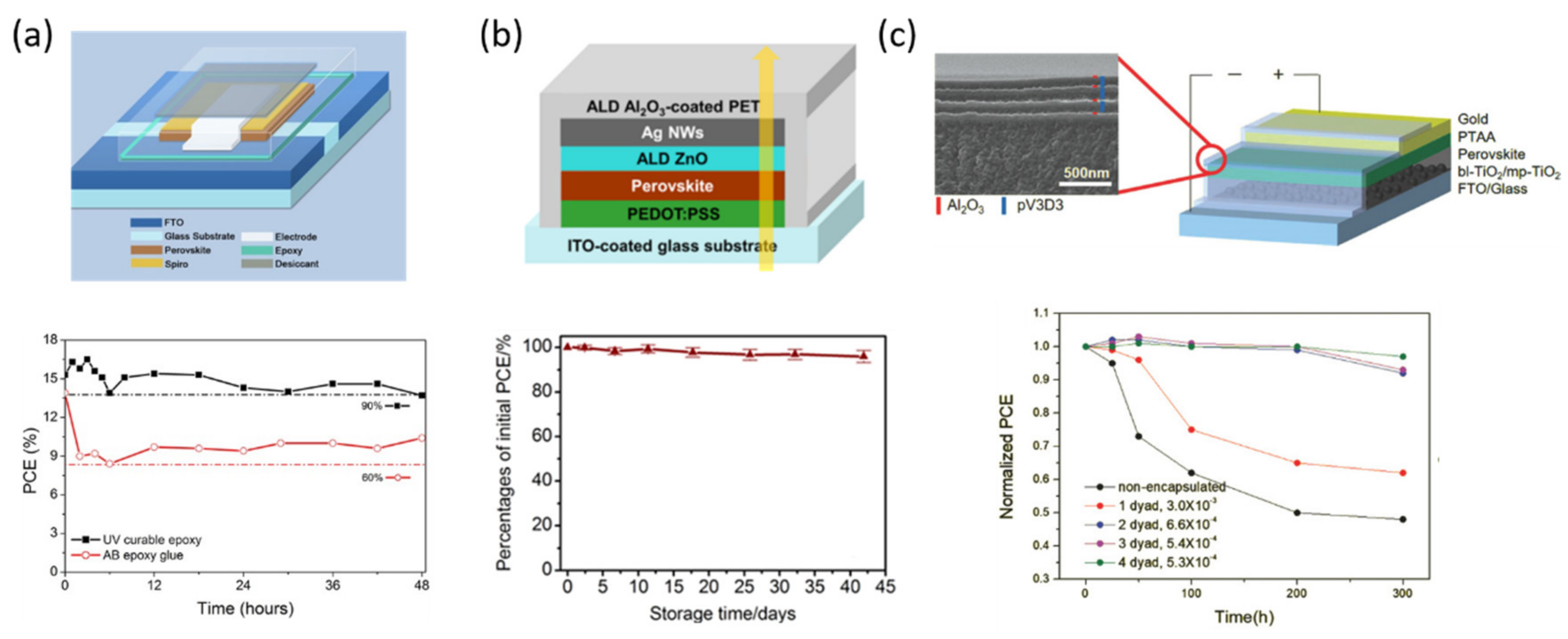
In 2016, Djurisic and co-workers (Figure 5a) reported an ~80% PCE of the original one after 48 h under continuous illumination, 85 °C, and relative humidity of 65% [83]. The perovskite devices were protected by a SiO2 film encapsulated with a UV-curable epoxy including a desiccant sheet. Upon the good results demonstrated through the established international summit on organic photovoltaic stability (ISOS) protocols for organic solar cell testing (ISOS-L2 and ISOS-O1); the authors realized that the method performed is not equally effective for ZnO-based devices, showing lower stability than TiO2 under the same conditions.
An example of an ALD deposition for encapsulation purposes is represented in Figure 5b. Here, Chang and co-workers reported the application of ALD to deposit ZnO and Al2O3 films as cathode buffer layer (CBL) and encapsulation layer, respectively, in an inverted planar perovskite configuration [84]. The authors noticed several advantages of this technique for the use in PSCs, including plastic-compatible processing temperature (80 °C), high charge selectivity, good electron-transporting ability, and excellent film coverage, performing as well with an OTR and WVTR low enough to improve the stability of the devices. The main advantage of this tactic is the possibility to manufacture the encapsulation stack in advance.
One of the latest approaches of TFE was reported by Lee et. al. in 2018. They proposed a multilayer stack of organic/inorganic layers deposited by initiated chemical vapor deposition (iCVD) and ALD, respectively [85]. The main target of their work was to remark the necessity to maximize the barrier performance of the TFE, while minimizing the PSC damage during the deposition of the inorganic layer. Coupling the iCVD with the ALD, they reported a PSC with a substantially enhanced long-term stability for 300 h under accelerated condition of 50 °C and 50% RH. The key of this work was the low-temperature fabrication (40 and 60 °C for iCVD and ALD, respectively), leading to a suitable WVTR and a PSC maintained 97% of its initial one.
4. Conclusions
Up to now, PSCs suffer outdoor instability since they are susceptible to harsh environmental conditions such as an extreme amount of UV rays, temperature, and high humidity. Attaining higher efficiency along with maintaining the stability throughout is a great challenge. Encapsulation of perovskite solar cells can play an effective role in improving the long term stability, since it can act as a barrier layer by restricting the diffusion of oxygen and moisture, resulting in the protection of the cathode interface and the active layer from deterioration. Herein, we provided a useful guide on the standard tests in order to certify PSCs stability in a unified and conventional way. Also, we overview the best and most used encapsulating materials and methods used to attain long-term PSCs operational lifetime. We believe that a thorough knowledge and understanding of the issues related with the different type of encapsulant is an essential requisite in order to improve PSCs stability and pave the way to the commercialization of this promising technology.
Author Contributions
Conceptualization, M.S., C.A.A., L.C.; writing—original draft preparation, C.A.A., L.C. and M.S.; writing—review and editing, C.A.A., L.C. and M.S.; visualization, C.A.A., L.C. and M.S.; supervision, C.A.A., L.C. and M.S.; project administration, M.S. All authors have read and agreed to the published version of the manuscript.
Funding
This research received no external funding.
Institutional Review Board Statement
Not applicable.
Informed Consent Statement
Not applicable.
Acknowledgments
M.S. thanks the National Research grant “Juan de la Cierva” (FJCI-2017-31761). C.A.A. thanks to the Helmholtz Young Investigator Group FRONTRUNNER.
Conflicts of Interest
The authors declare no conflict of interest.
References
- Kojima, A.; Teshima, K.; Shirai, Y.; Miyasaka, T. Organometal halide perovskites as visible-light sensitizers for photovoltaic cells. J. Am. Chem. Soc. 2009, 131, 6050–6051. [Google Scholar] [CrossRef] [PubMed]
- Deepa, M.; Salado, M.; Calio, L.; Kazim, S.; Shivaprasad, S.M.; Ahmad, S. Cesium power: Low Cs+ levels impart stability to perovskite solar cells. Phys. Chem. Chem. Phys. 2017, 19, 4069–4077. [Google Scholar] [CrossRef] [PubMed]
- Wang, T.; Zhang, H.; Hou, S.; Zhang, Y.; Li, Q.; Zhang, Z.; Gao, H.; Mao, A.Y. Facile synthesis of methylammonium lead iodide perovskite with controllable morphologies with enhanced luminescence performance. Nanomaterials 2019, 9, 1660. [Google Scholar] [CrossRef] [PubMed] [Green Version]
- Salado, M.; Idigoras, J.; Calio, L.; Kazim, S.; Nazeeruddin, M.K.; Anta, J.A.; Ahmad, S. Interface play between perovskite and hole selective layer on the performance and stability of perovskite solar cells. ACS Appl. Mater. Interfaces 2016, 8, 34414–34421. [Google Scholar] [CrossRef]
- Al-Ashouri, A.; Köhnen, E.; Li, B.; Magomedov, A.; Hempel, H.; Caprioglio, P.; Márquez, J.A.; Vilches, A.B.M.; Kasparavicius, E.; Smith, J.A.; et al. Monolithic perovskite/silicon tandem solar cell with >29% efficiency by enhanced hole extraction. Science 2020, 370, 1300–1309. [Google Scholar] [CrossRef] [PubMed]
- Rao, M.K.; Sangeetha, D.; Selvakumar, M.; Sudhakar, Y.; Mahesha, M. Review on persistent challenges of perovskite solar cells’ stability. Sol. Energy 2021, 218, 469–491. [Google Scholar] [CrossRef]
- Stoichkov, V.; Bristow, N.; Troughton, J.; De Rossi, F.; Watson, T.; Kettle, J. Outdoor performance monitoring of perovskite solar cell mini-modules: Diurnal performance, observance of reversible degradation and variation with climatic performance. Sol. Energy 2018, 170, 549–556. [Google Scholar] [CrossRef] [Green Version]
- Velilla, E.; Ramirez, D.; Uribe, J.-I.; Montoya, J.F.; Jaramillo, F. Outdoor performance of perovskite solar technology: Silicon comparison and competitive advantages at different irradiances. Sol. Energy Mater. Sol. Cells 2019, 191, 15–20. [Google Scholar] [CrossRef]
- Lee, S.-W.; Kim, S.; Bae, S.; Cho, K.; Chung, T.; Mundt, L.E.; Lee, S.; Park, S.; Park, H.; Schubert, M.C.; et al. UV degradation and recovery of perovskite solar cells. Sci. Rep. 2016, 6, 38150. [Google Scholar] [CrossRef] [Green Version]
- Zhang, H.; Qiao, X.; Shen, Y.; Wang, M. Effect of temperature on the efficiency of organometallic perovskite solar cells. J. Energy Chem. 2015, 24, 729–735. [Google Scholar] [CrossRef]
- Seo, S.; Jeong, S.; Bae, C.; Park, N.-G.; Shin, H. Perovskite solar cells with inorganic electron- and hole-transport layers exhibiting long-term (≈500 h) stability at 85 °C under continuous 1 sun illumination in ambient air. Adv. Mater. 2018, 30, e1801010. [Google Scholar] [CrossRef]
- Senocrate, A.; Acartuerk, T.; Kim, G.Y.; Merkle, R.; Starke, U.; Grätzel, M.; Maier, J. Interaction of oxygen with halide perovskites. J. Mater. Chem. A 2018, 6, 10847–10855. [Google Scholar] [CrossRef] [Green Version]
- Mishra, A.K.; Shukla, R. Effect of humidity in the perovskite solar cell. Mater. Today Proc. 2020, 29, 836–838. [Google Scholar] [CrossRef]
- Song, Z.; Abate, A.; Watthage, S.C.; Liyanage, G.K.; Phillips, A.B.; Steiner, U.; Graetzel, M.; Heben, M.J. In-situ observation of moisture-induced degradation of perovskite solar cells using laser-beam induced current. In Proceedings of the 2016 IEEE 43rd Photovoltaic Specialists Conference (PVSC), Portland, OR, USA, 5–10 June 2016; pp. 1202–1206. [Google Scholar]
- Leijtens, T.; Eperon, G.E.; Pathak, S.; Abate, A.; Lee, M.M.; Snaith, H.J. Overcoming ultraviolet light instability of sensitized TiO2 with meso-superstructured organometal trihalide perovskite solar cells. Nat. Commun. 2013, 4, 2885. [Google Scholar] [CrossRef] [PubMed]
- Niu, G.; Guo, X.; Wang, L. Review of recent progress in chemical stability of perovskite solar cells. J. Mater. Chem. A 2015, 3, 8970–8980. [Google Scholar] [CrossRef]
- Chander, N.; Khan, A.F.; Chandrasekhar, P.S.; Thouti, E.; Swami, S.K.; Dutta, V.; Komarala, V.K. Reduced ultraviolet light induced degradation and enhanced light harvesting using YVO4:Eu3+ down-shifting nano-phosphor layer in organometal halide perovskite solar cells. Appl. Phys. Lett. 2014, 105, 033904. [Google Scholar] [CrossRef]
- Dualeh, A.; Gao, P.; Seok, S.I.; Nazeeruddin, M.K.; Grätzel, M. Thermal behavior of methylammonium lead-trihalide perovskite photovoltaic light harvesters. Chem. Mater. 2014, 26, 6160–6164. [Google Scholar] [CrossRef]
- Conings, B.; Drijkoningen, J.; Gauquelin, N.; Babayigit, A.; Conings, B.; Drijkoningen, J.; Gauquelin, N.; Babayigit, A.; D’Haen, J.; D’Olieslaeger, L.; et al. Intrinsic thermal instability of methylammonium lead trihalide perovskite. Adv. Energy Mater. 2015, 5, 1–8. [Google Scholar] [CrossRef]
- Pisoni, A.; Jacimovic, J.; Barisic, O.S.; Spina, M.; Gaál, R.; Forró, L.; Horváth, E. Ultra-low thermal conductivity in organic–inorganic hybrid perovskite CH3NH3PbI3. J. Phys. Chem. Lett. 2014, 5, 2488–2492. [Google Scholar] [CrossRef] [PubMed] [Green Version]
- Pistor, P.; Borchert, J.; Fränzel, W.; Csuk, R.; Scheer, R. Monitoring the phase formation of coevaporated lead halide perovskite thin films by in situ X-ray diffraction. J. Phys. Chem. Lett. 2014, 5, 3308–3312. [Google Scholar] [CrossRef] [PubMed]
- Aristidou, N.; Sanchez-Molina, I.; Chotchuangchutchaval, T.; Brown, M.; Martinez, L.; Rath, T.; Haque, S.A. The role of oxygen in the degradation of methylammonium lead trihalide perovskite photoactive layers. Angew. Chem. Int. Ed. 2015, 54, 8208–8212. [Google Scholar] [CrossRef] [PubMed] [Green Version]
- Han, H. Oxygen makes better inorganic perovskite solar cells. Sci. Bull. 2020, 65, 335–336. [Google Scholar] [CrossRef] [Green Version]
- Zhang, Z.; Liu, Y.; Zhang, P.; Mao, Y. Natural passivation of the perovskite layer by oxygen in ambient air to improve the efficiency and stability of perovskite solar cells simultaneously. Org. Electron. 2021, 88, 106007. [Google Scholar] [CrossRef]
- Zhu, Z.; Bai, Y.; Liu, X.; Chueh, C.-C.; Yang, S.; Jen, A.K.-Y. Enhanced efficiency and stability of inverted perovskite solar cells using highly crystalline SnO2 nanocrystals as the robust electron-transporting layer. Adv. Mater. 2016, 28, 6478–6484. [Google Scholar] [CrossRef] [PubMed]
- Meng, L.; You, J.; Yang, Y. Addressing the stability issue of perovskite solar cells for commercial applications. Nat. Commun. 2018, 9, 1–4. [Google Scholar] [CrossRef] [PubMed]
- Stoumpos, C.C.; Malliakas, C.D.; Kanatzidis, M.G. Semiconducting tin and lead iodide perovskites with organic cations: Phase transitions, high mobilities, and near-infrared photoluminescent properties. Inorg. Chem. 2013, 52, 9019–9038. [Google Scholar] [CrossRef] [PubMed]
- Poglitsch, A.; Weber, D.A. Dynamic disorder in methylammoniumtrihalogenoplumbates (II) observed by millimeter-wave spectroscopy. J. Chem. Phys. 1987, 87, 6373–6378. [Google Scholar] [CrossRef]
- Khenkin, M.V.; Katz, E.A.; Abate, A.; Bardizza, G.; Berry, J.J.; Brabec, C.; Brunetti, F.; Bulović, V.; Burlingame, Q.; Di Carlo, A.; et al. Consensus statement for stability assessment and reporting for perovskite photovoltaics based on ISOS procedures. Nat. Energy 2020, 5, 35–49. [Google Scholar] [CrossRef]
- Weber, O.; Charles, B.; Weller, M.T. Phase behaviour and composition in the formamidinium-methylammonium hybrid lead iodide perovskite solid solution. J. Mater. Chem. A 2016, 4, 15375–15382. [Google Scholar] [CrossRef] [Green Version]
- Binek, A.; Hanusch, F.C.; Docampo, P.; Bein, T. Stabilization of the trigonal high-temperature phase of formamidinium lead iodide. J. Phys. Chem. Lett. 2015, 6, 1249–1253. [Google Scholar] [CrossRef] [PubMed]
- Li, Z.; Yang, M.; Park, J.-S.; Wei, S.-H.; Berry, J.J.; Zhu, K. Stabilizing perovskite structures by tuning tolerance factor: Formation of formamidinium and cesium lead iodide solid-state alloys. Chem. Mater. 2016, 28, 284–292. [Google Scholar] [CrossRef]
- Noh, J.H.; Im, S.H.; Heo, J.H.; Mandal, T.N.; Seok, S.I. Chemical management for colorful, efficient, and stable inorganic-organic hybrid nanostructured solar cells. Nano Lett. 2013, 13, 1764–1769. [Google Scholar] [CrossRef]
- Eperon, G.E.; Stranks, S.D.; Menelaou, C.; Johnston, M.B.; Herz, L.M.; Snaith, H.J. Formamidinium lead trihalide: A broadly tunable perovskite for efficient planar heterojunction solar cells. Energy Environ. Sci. 2014, 7, 982–988. [Google Scholar] [CrossRef]
- McMeekin, D.P.; Sadoughi, G.; Rehman, W.; Eperon, G.E.; Saliba, M.; Hörantner, M.T.; Haghighirad, A.; Sakai, N.; Korte, L.; Rech, B.; et al. A mixed-cation lead mixed-halide perovskite absorber for tandem solar cells. Science 2016, 351, 151–155. [Google Scholar] [CrossRef] [Green Version]
- Saliba, M.; Matsui, T.; Seo, J.-Y.; Domanski, K.; Correa-Baena, J.-P.; Nazeeruddin, M.K.; Zakeeruddin, S.M.; Tress, W.; Abate, A.; Hagfeldt, A.; et al. Cesium-containing triple cation perovskite solar cells: Improved stability, reproducibility and high efficiency. Energy Environ. Sci. 2016, 9, 1989–1997. [Google Scholar] [CrossRef] [PubMed] [Green Version]
- Saliba, M.; Matsui, T.; Domanski, K.; Seo, J.-Y.; Ummadisingu, A.; Zakeeruddin, S.M.; Correa-Baena, J.-P.; Tress, W.R.; Abate, A.; Hagfeldt, A.; et al. Incorporation of rubidium cations into perovskite solar cells improves photovoltaic performance. Science 2016, 354, 206–209. [Google Scholar] [CrossRef] [PubMed]
- Caliò, L.; Salado, M.; Kazim, S.; Ahmad, S. A generic route of hydrophobic doping in hole transporting material to increase longevity of perovskite solar cells. Joule 2018, 2, 1800–1815. [Google Scholar] [CrossRef] [Green Version]
- Wang, Z.; Shi, Z.; Li, T.; Chen, Y.; Huang, W. Stability of perovskite solar cells: A prospective on the substitution of the A cation and X anion. Angew. Chem. Int. Ed. 2017, 56, 1190–1212. [Google Scholar] [CrossRef]
- Tan, S.; Yavuz, I.; Weber, M.H.; Huang, T.; Chen, C.-H.; Wang, R.; Wang, H.-C.; Ko, J.H.; Nuryyeva, S.; Xue, J.; et al. Shallow iodine defects accelerate the degradation of α-phase formamidinium perovskite. Joule 2020, 4, 2426–2442. [Google Scholar] [CrossRef]
- Corsini, F.; Griffini, G. Recent progress in encapsulation strategies to enhance the stability of organometal halide perovskite solar cells. J. Phys. Energy 2020, 2, 031002. [Google Scholar] [CrossRef]
- Peng, J.; Walter, D.; Ren, Y.; Tebyetekerwa, M.; Wu, Y.; Duong, T.; Lin, Q.; Li, J.; Lu, T.; Mahmud, A.; et al. Nanoscale localized contacts for high fill factors in polymer-passivated perovskite solar cells. Science 2021, 371, 390–395. [Google Scholar] [CrossRef]
- Cheacharoen, R.; Boyd, C.C.; Burkhard, G.F.; Leijtens, T.; Raiford, J.A.; Bush, K.A.; Bent, S.F.; McGehee, M.D. Encapsulating perovskite solar cells to withstand damp heat and thermal cycling. Sustain. Energy Fuels 2018, 2, 2398–2406. [Google Scholar] [CrossRef]
- Idígoras, J.; Aparicio, F.J.; Contreras-Bernal, L.; Ramos-Terrón, S.; Alcaire, M.; Sánchez-Valencia, J.R.; Borras, A.; Barranco, Á.; Anta, J.A. Enhancing moisture and water resistance in perovskite solar cells by encapsulation with ultrathin plasma polymers. ACS Appl. Mater. Interfaces 2018, 10, 11587–11594. [Google Scholar] [CrossRef]
- Shi, L.; Young, T.L.; Kim, J.; Sheng, Y.; Wang, L.; Chen, Y.; Feng, Z.; Keevers, M.J.; Hao, X.; Verlinden, P.J.; et al. Accelerated lifetime testing of organic-inorganic perovskite solar cells encapsulated by polyisobutylene. ACS Appl. Mater. Interfaces 2017, 9, 25073–25081. [Google Scholar] [CrossRef] [PubMed]
- Ma, S.; Bai, Y.; Wang, H.; Zai, H.; Wu, J.; Li, L.; Xiang, S.; Liu, N.; Liu, L.; Zhu, C.; et al. 1000 h operational lifetime perovskite solar cells by ambient melting encapsulation. Adv. Energy Mater. 2020, 10, 1–8. [Google Scholar] [CrossRef]
- Jacobsson, T.J.; Correa-Baena, J.-P.; Pazoki, M.; Saliba, M.; Schenk, K.; Grätzel, M.; Hagfeldt, A. Exploration of the compositional space for mixed lead halogen perovskites for high efficiency solar cells. Energy Environ. Sci. 2016, 9, 1706–1724. [Google Scholar] [CrossRef]
- Nikbakht, H.; Shalan, A.E.; Salado, M.; Assadi, A.; Boroojerdian, P.; Kazim, S.; Ahmad, S. Polymer amplification to improve performance and stability toward semitransparent perovskite solar cells fabrication. Energy Technol. 2020, 8, 1–9. [Google Scholar] [CrossRef] [Green Version]
- Available online:https://sauletech.com/ (accessed on 28 April 2021).
- Gan, Y.; Bi, X.; Liu, Y.; Qin, B.; Li, Q.; Jiang, Q.; Mo, P. Numerical investigation energy conversion performance of tin-based perovskite solar cells using cell capacitance simulator. Energies 2020, 13, 5907. [Google Scholar] [CrossRef]
- Yang, W.-F.; Cao, J.-J.; Dong, C.; Li, M.; Tian, Q.-S.; Wang, Z.-K.; Liao, L.-S. Suppressed oxidation of tin perovskite by Catechin for eco-friendly indoor photovoltaics. Appl. Phys. Lett. 2021, 118, 023501. [Google Scholar] [CrossRef]
- Jagadamma, L.K.; Blaszczyk, O.; Sajjad, M.T.; Ruseckas, A.; Samuel, I.D. Efficient indoor pin hybrid perovskite solar cells using low temperature solution processed NiO as hole extraction layers. Sol. Energy Mater. Sol. Cells 2019, 201. [Google Scholar] [CrossRef] [Green Version]
- Castro-Hermosa, S.; Lucarelli, G.; Top, M.; Fahland, M.; Fahlteich, J.; Brown, T.M. Perovskite photovoltaics on roll-to-roll coated ultra-thin glass as flexible high-efficiency indoor power generators. Cell Rep. Phys. Sci. 2020, 1, 100045. [Google Scholar] [CrossRef]
- Hou, X.; Wang, Y.; Lee, H.K.H.; Datt, R.; Miano, N.U.; Yan, D.; Li, M.; Zhu, F.; Hou, B.; Tsoi, W.C.; et al. Indoor application of emerging photovoltaics—Progress, challenges and perspectives. J. Mater. Chem. A 2020, 8, 21503–21525. [Google Scholar] [CrossRef]
- Aranda, C.; Guerrero, A.; Bisquert, J. Crystalline clear or not: Beneficial and harmful effects of water in perovskite solar cells. ChemPhysChem 2019, 20, 2587–2599. [Google Scholar] [CrossRef] [Green Version]
- Uddin, A.; Upama, M.B.; Yi, H.; Duan, L. Encapsulation of organic and perovskite solar cells: A review. Coatings 2019, 9, 65. [Google Scholar] [CrossRef] [Green Version]
- Contreras-Bernal, L.; Aranda, C.; Valles-Pelarda, M.; Ngo, T.T.; Ramos-Terrón, S.; Gallardo, J.J.; Navas, J.; Guerrero, A.; Mora-Seró, I.; Idígoras, J.; et al. Homeopathic perovskite solar cells: Effect of humidity during fabrication on the performance and stability of the device. J. Phys. Chem. C 2018, 122, 5341–5348. [Google Scholar] [CrossRef]
- Jiang, Y.; Qiu, L.; Juarez-Perez, E.J.; Ono, L.K.; Hu, Z.; Liu, Z.; Wu, Z.; Meng, L.; Wang, Q.; Qi, Y. Reduction of lead leakage from damaged lead halide perovskite solar modules using self-healing polymer-based encapsulation. Nat. Energy 2019, 4, 585–593. [Google Scholar] [CrossRef]
- Kim, H.-S.; Seo, J.-Y.; Park, N.-G. Material and device stability in perovskite solar cells. ChemSusChem 2016, 9, 2528–2540. [Google Scholar] [CrossRef] [PubMed]
- Kulbak, M.; Gupta, S.; Kedem, N.; Levine, I.; Bendikov, T.; Hodes, G.; Cahen, D. Cesium enhances long-term stability of lead bromide perovskite-based solar cells. J. Phys. Chem. Lett. 2016, 7, 167–172. [Google Scholar] [CrossRef] [PubMed] [Green Version]
- Guarnera, S.; Abate, A.; Zhang, W.; Foster, J.M.; Richardson, G.; Petrozza, A.; Snaith, H.J. Improving the long-term stability of perovskite solar cells with a porous Al2O3 buffer layer. J. Phys. Chem. Lett. 2015, 6, 432–437. [Google Scholar] [CrossRef] [PubMed] [Green Version]
- Griffini, G.; Turri, S. Polymeric materials for long-term durability of photovoltaic systems. J. Appl. Polym. Sci. 2015, 133, 1–16. [Google Scholar] [CrossRef] [Green Version]
- Cros, S.; de Bettignies, R.; Berson, S.; Bailly, S.; Maisse, P.; Lemaitre, N.; Guillerez, S. Definition of encapsulation barrier requirements: A method applied to organic solar cells. Sol. Energy Mater. Sol. Cells 2011, 95, S65–S69. [Google Scholar] [CrossRef]
- Berghold, J.; Koch, S.; Frohmann, B.; Hacke, P.; Grunow, P. Properties of encapsulation materials and their relevance for recent field failures. In Proceedings of the IEEE 40th Photovoltaic Specialist Conference (PVSC), Denver, CO, USA, 8–13 June 2014; pp. 1987–1992. [Google Scholar]
- Spanggaard, H.; Krebs, F.C. A brief history of the development of organic and polymeric photovoltaics. Sol. Energy Mater. Sol. Cells 2004, 83, 125–146. [Google Scholar] [CrossRef]
- Shaheen, S.E.; Ginley, D.S.; Jabbour, G.E. Organic-based photovoltaics: Toward low-cost power generation. MRS Bull. 2005, 30, 10–19. [Google Scholar] [CrossRef] [Green Version]
- Luo, W.; Khoo, Y.S.; Hacke, P.; Naumann, V.; Lausch, D.; Harvey, S.P.; Singh, J.P.; Chai, J.; Wang, Y.; Aberle, A.G.; et al. Potential-induced degradation in photovoltaic modules: A critical review. Energy Environ. Sci. 2017, 10, 43–68. [Google Scholar] [CrossRef] [Green Version]
- Wang, D.; Wright, M.; Elumalai, N.K.; Uddin, A. Stability of perovskite solar cells. Sol. Energy Mater. Sol. Cells 2016, 147, 255–275. [Google Scholar] [CrossRef]
- Greenhouse, H. Hermeticity of Electronic Packages; Elsevier: Amsterdam, The Netherlands, 2012. [Google Scholar]
- Bush, K.A.; Palmstrom, A.F.; Yu, Z.J.; Boccard, M.; Cheacharoen, R.; Mailoa, J.P.; McMeekin, D.P.; Hoye, R.L.Z.; Bailie, C.D.; Leijtens, T.; et al. 23.6%-efficient monolithic perovskite/silicon tandem solar cells with improved stability. Nat. Energy 2017, 2, 17009. [Google Scholar] [CrossRef]
- Matteocci, F.; Cinà, L.; Lamanna, E.; Cacovich, S.; Divitini, G.; Midgley, P.A.; Ducati, C.; Di Carlo, A. Encapsulation for long-term stability enhancement of perovskite solar cells. Nano Energy 2016, 30, 162–172. [Google Scholar] [CrossRef] [Green Version]
- Cuddihy, E.F.; Baum, B.; Willis, P. Low-cost encapsulation materials for terrestrial solar cell modules. Sol. Energy 1979, 22, 389–396. [Google Scholar] [CrossRef]
- Liu, H.; Feng, J.; Nicoli, E.; López, L.; Kauffmann, K.; Yang, K.; Ramesh, N. Predicting the reliability of polyisobutylene seal for photovoltaic application. In Reliability of Photovoltaic Cells, Modules, Components, and Systems V; SPIE: Bellingham, WA, USA, 2012; Volume 8472. [Google Scholar]
- Burschka, J.; Pellet, N.; Moon, S.-J.; Humphry-Baker, R.; Gao, P.; Nazeeruddin, M.K.; Grätzel, M. Sequential deposition as a route to high-performance perovskite-sensitized solar cells. Nat. Cell Biol. 2013, 499, 316–319. [Google Scholar] [CrossRef]
- Ramasamy, E.; Karthikeyan, V.; Rameshkumar, K.; Veerappan, G. Glass-to-glass encapsulation with ultraviolet light curable epoxy edge sealing for stable perovskite solar cells. Mater. Lett. 2019, 250, 51–54. [Google Scholar] [CrossRef]
- Martins, J.; Emami, S.; Madureira, R.; Mendes, J.; Ivanou, D.; Mendes, A. Novel laser-assisted glass frit encapsulation for long-lifetime perovskite solar cells. J. Mater. Chem. A 2020, 8, 20037–20046. [Google Scholar] [CrossRef]
- Alvarez, A.O.; Arcas, R.; Aranda, C.A.; Bethencourt, L.; Mas-Marzá, E.; Saliba, M.; Fabregat-Santiago, F. Negative capacitance and inverted hysteresis: Matching features in perovskite solar cells. J. Phys. Chem. Lett. 2020, 11, 8417–8423. [Google Scholar] [CrossRef]
- Weerasinghe, H.C.; Dkhissi, Y.; Scully, A.D.; Caruso, R.A.; Cheng, Y.-B. Encapsulation for improving the lifetime of flexible perovskite solar cells. Nano Energy 2015, 18, 118–125. [Google Scholar] [CrossRef]
- Li, B.; Wang, M.; Subair, R.; Cao, G.; Tian, J. Significant stability enhancement of perovskite solar cells by facile adhesive encapsulation. J. Phys. Chem. C 2018, 122, 25260–25267. [Google Scholar] [CrossRef]
- Castro-Hermosa, S.; Top, M.; Dagar, J.; Fahlteich, J.; Brown, T.M. Quantifying performance of permeation barrier—Encapsulation systems for flexible and glass-based electronics and their application to perovskite solar cells. Adv. Electron. Mater. 2019, 5, 1–11. [Google Scholar] [CrossRef] [Green Version]
- Li, L.; Zhang, S.; Yang, Z.; Berthold, E.E.S.; Chen, W. Recent advances of flexible perovskite solar cells. J. Energy Chem. 2018, 27, 673–689. [Google Scholar] [CrossRef] [Green Version]
- Kim, H.; Lee, J.; Kim, B.; Byun, H.R.; Kim, S.H.; Oh, H.M.; Baik, S.; Jeong, M.S. Enhanced stability of MAPbI3 perovskite solar cells using poly(p-chloro-xylylene) encapsulation. Sci. Rep. 2019, 9, 1–6. [Google Scholar] [CrossRef] [Green Version]
- Dong, Q.; Liu, F.; Wong, M.K.; Tam, H.W.; Djurišić, A.B.; Ng, A.; Surya, C.; Chan, W.K.; Ng, A.M.C. Encapsulation of perovskite solar cells for high humidity conditions. ChemSusChem 2016, 9, 2597–2603. [Google Scholar] [CrossRef] [PubMed]
- Chang, C.-Y.; Lee, K.-T.; Huang, W.-K.; Siao, H.-Y.; Chang, Y.-C. High-performance, air-stable, low-temperature processed semitransparent perovskite solar cells enabled by atomic layer deposition. Chem. Mater. 2015, 27, 5122–5130. [Google Scholar] [CrossRef]
- Lee, Y.I.; Jeon, N.J.; Kim, B.J.; Shim, H.; Yang, T.-Y.; Seok, S.I.; Seo, J.; Im, S.G. A low-temperature thin-film encapsulation for enhanced stability of a highly efficient perovskite solar cell. Adv. Energy Mater. 2018, 8, 1–8. [Google Scholar] [CrossRef]
Figure 1.
Schematic representation of different factors affecting the stability of perovskite solar cells.
Figure 1.
Schematic representation of different factors affecting the stability of perovskite solar cells.

Figure 2.
(a) Schematic representation of polymer addition in MAPbI3. Visual image of the perovskite layers with (b) routine concentration of 1.2 m (≈400 nm perovskite thickness; (c) 0.5 m perovskite with P(VDF-TrFE) (≈150 nm perovskite thickness) showing semi-transparent effect and (d) transmittance spectra of two different concentrations of MAPbI3 and with P(VDF-TrFE) [48]. (e) A pilot installation of perovskite solar cell in Spark office building’s façade in Warsaw (Reproduced with permission of [37] and (f) a photo of the fabricated cells, with different perovskite composition, showing the appearance in reflected light. Reproduced with permission of [47].

Figure 3.
Glass-to-glass encapsulation methods. (a) Schematic illustration of polyisobutylene (PIB) blanket used as cover encapsulant and edge sealant for perovskite solar cell and its corresponding normalized PCE during thermal cycle test. Reproduced with permission of Ref. [45]. (b) Top-row of glass-to-glass encapsulation of PSC with UV-curable epoxy edge sealant and its corresponding normalized PCE during stability test. Reproduced with permission of Ref. [75]. (c) Scheme of laser-assisted glass frit sealing process with dual laser beam configuration and its corresponding normalized PCE during stability test. Reproduced with permission of Ref. [76].

Figure 4.
Polymer encapsulation methods. (a) Scheme of a flexible indium-doped, zinc oxide-coated polyethylene terephthalate (IZO-PET) barrier encapsulant film with integrated adhesive. Reproduced with permission of Ref. [78]. (b) Scheme of adhesive encapsulation by employing commercial polyimide tape on perovskite solar cells and its corresponding normalized PCE during stability test. Reproduced with permission of Ref. [79]. (c) Layouts used to measure degradation of calcium sensors (left) and perovskite solar cells (PSC, right). Different barriers used, including PET, glass, and ultra-high permeation barrier films (UHPBF). Reproduced with permission of Ref. [80].

Figure 5.
Thin-film encapsulation methods. (a) Diagram of the encapsulated cells with its corresponding average PCE during stability test. Reproduced with permission of Ref. [83]. (b) Schematic representation of semi-transparent (ST) perovskite solar cell by ALD technology to deposit ZnO and Al2O3. Reproduced with permission of Ref. [84]. (c) Schematic design of the packaged PSC (on the right), and cross-sectional SEM image of the TFE multilayer. Reproduced with permission of Ref. [85].


Table 1.
Summary of the different crystal structure depending on the composition and the temperature of the perovskite material.
Table 1.
Summary of the different crystal structure depending on the composition and the temperature of the perovskite material.
| Perovskite | Non-Optical Active | Low T | Medium T | High T | Ref. | |
|---|---|---|---|---|---|---|
| Pure | MAPbI3 | <162.2 K (orthorhombic) | 162.2–327.4 K (tetragonal) | >327.4 K (cubic) | [27] | |
| MAPbBr3 | 149.5–155.1 K (tetragonal) | 155.1–236.9 K (tetragonal) | >236.9 K (cubic) | [28] | ||
| FAPbI3 | <438 K (hexagonal) | 140–285 K (tetragonal) | >285 K (cubic) | [29] | ||
| CsPbI3 | <588 K (orthorhombic) | >588 K (cubic) | ||||
| Mixed A-cation | FAxMA1-xPbI3 | forms if x > 0.85 | <257–283 K (cubic) | <298 to >523 K (tetragonal) | [30,31] | |
| FAxCs1-xPbI3 | <398 K, x = 0.85 (hexagonal) | >398 K, x = 0.85 (tetragonal) | [32] | |||
| Mixed X-anion | MAPb(I1-xBrx)3 | 298 K, tetragonal for x ≤ 0.13, cubic for x ≥ 0.2 | [33] | |||
| FAPb(I1-xBrx)3 | amorphous phase for x = 0.3 to 0.5 | 298 K, trigonal for x < 0.3, cubic for x > 0.5, possibly metastable | [34] | |||
| Mixed cation-anion | FA0.83Cs0.17Pb(I1-xBrx)3 | 298 K, (cubic) | [35] | |||
| FA0.75MA0.15Cs0.10Pb(I0.83Br0.17)3 | 298 K (cubic) | [36] | ||||
| FA0.75MA0.15Cs0.05Rb0.05Pb(I0.83Br0.17)3 | 298 K (not specified) | [37] |
Table 2.
Summary of the test performed at the IEC 61215:2016, the chemical reaction proposed depending on the external parameter [39].
Table 2.
Summary of the test performed at the IEC 61215:2016, the chemical reaction proposed depending on the external parameter [39].
| Temperature | |
| Thermal cycling test. | |
| The modules are brought into a climatic chamber with temperature control. Air circulates inside to minimize condensation. The modules are cycled 50 (Sequence C) or 200 times (Sequence D) between −40 to 85 °C with at least a dwell time of 10 min. | |
| At temperatures higher than 150 °C, the perovskite readily decomposes in an endothermic reaction into its components PbI2, CH3NH2, and HI. In addition, temperature cycling induces encapsulation delamination entailing iodine loses [40]. | |
| Humidity | |
| Damp heat test. |
|
| Humidity exposure on a long-time scale is tested. The module is held at 85 ± 2 °C at a RH of 85 ± 5% for 1000–1048 h. Afterwards, the module is recovered for 2 to 4 h at 23 ± 5 °C and a RH of less than 75% at short-circuit. | |
| Water molecules easily penetrate the perovskite structure and form an intermediate monohydrate and dihydrate perovskite. Although theses intermediates are reversible after dry conditions, water molecules weak the bond between the cation and the PbI6, allowing for faster deprotonation of the organic cation. | |
| UV-light | |
| UV preconditioning. |
|
| The cells are exposed to UV-light before 50 thermal cycles and the humidity freeze test. With this, materials and adhesive bonds, that are prone to degrade under UV light, can be identified. The module is kept at 60 ± 5 °C. | |
| The effect of UV light on perovskite solar cell stability is most significant when combined with other factors (e.g., moisture or oxygen exposure). Moreover, two-stage UV degradation process should be avoided in TiO2-based perovskites devices. | |
Table 3.
Requirements for encapsulant material and technological approaches for sustainable and large-scale encapsulation processes.
Table 3.
Requirements for encapsulant material and technological approaches for sustainable and large-scale encapsulation processes.
| Material | Technology |
|---|---|
| Good processability | Suitable patterning strategy:
|
| Chemical inertness | Cleanness of PSC edges |
| Low oxygen transmission rate (OTR) | Large-scale applicability |
| Low water vapor transmission rate (WVTR) | Reduced fabrication costs |
| Total light transmission | |
| High dielectric constant | |
| Resistance to UV and thermal oxidation | |
| Good mechanical strength | |
| High adhesion to PSC modules | |
| Similar coefficient of thermal expansion of PSC materials | |
| High flexibility |
Publisher’s Note: MDPI stays neutral with regard to jurisdictional claims in published maps and institutional affiliations. |
© 2021 by the authors. Licensee MDPI, Basel, Switzerland. This article is an open access article distributed under the terms and conditions of the Creative Commons Attribution (CC BY) license (https://creativecommons.org/licenses/by/4.0/).
Share and Cite
MDPI and ACS Style
Aranda, C.A.; Caliò, L.; Salado, M. Toward Commercialization of Stable Devices: An Overview on Encapsulation of Hybrid Organic-Inorganic Perovskite Solar Cells. Crystals 2021, 11, 519. https://0-doi-org.brum.beds.ac.uk/10.3390/cryst11050519
AMA Style
Aranda CA, Caliò L, Salado M. Toward Commercialization of Stable Devices: An Overview on Encapsulation of Hybrid Organic-Inorganic Perovskite Solar Cells. Crystals. 2021; 11(5):519. https://0-doi-org.brum.beds.ac.uk/10.3390/cryst11050519
Chicago/Turabian StyleAranda, Clara A., Laura Caliò, and Manuel Salado. 2021. "Toward Commercialization of Stable Devices: An Overview on Encapsulation of Hybrid Organic-Inorganic Perovskite Solar Cells" Crystals 11, no. 5: 519. https://0-doi-org.brum.beds.ac.uk/10.3390/cryst11050519
Note that from the first issue of 2016, this journal uses article numbers instead of page numbers. See further details here.