Article

Investigation of the Wear Behavior of Surface Welding AZ91 and AZ91+Gd Alloys under Variable Loading Conditions

1
School of Mechanical and Electronic Engineering, Shandong Jianzhu University, Jinan 250000, China
2
School of Materials Science and Engineering, Shandong Jianzhu University, Jinan 250000, China
3
Shandong Research Institute of Industrial Technology Additive Manufacturing Collaborative Innovation Center, Jinan 250000, China
4
Jiangsu Haoran Spray Forming Alloy Co., Ltd., Zhenjiang 212000, China
*
Author to whom correspondence should be addressed.
Submission received: 2 April 2021 / Revised: 9 May 2021 / Accepted: 12 May 2021 / Published: 16 May 2021

Abstract

:
Adding rare earth elements to magnesium alloys is an effective way to improve their wear resistance. However, the effect achieved is closely related to the friction condition. In this paper, two different types of welding wires, AZ91 magnesium alloy and AZ91 + gadolinium (Gd), were used for surface welding. Dry sliding friction and wear experiments were performed on the surfacing alloys using the pin-on-disc test. The effects of Gd addition on the wear resistance and wear mechanism of the alloy were systematically studied under low to high loads. The results show that as the load increases, the friction coefficient of the surfacing AZ91 alloy gradually decreases as the wear rate increases. A mild–severe wear transition occurred at 100 N. The addition of Gd only slightly increased the wear rate under a load of 15 N. The wear rate was significantly decreased with loads in the range of 30 to 100 N and mild–severe wear transition was avoided. The influence of both Gd addition and load on the wear mechanism were considered. The overall wear resistance of the surfacing magnesium alloy was determined.

1. Introduction

Magnesium alloys offer several advantages associated with their low density, high specific strength, and high damping capacities. In addition to their use as lightweight construction materials, magnesium alloys have been widely used in aerospace, digital communications, and other industries [1]. During operation, local damage such as wear and scratches will inevitably occur on the surface of structural parts or components. If wear is not managed in a timely manner, local damage accumulation can lead to failure of the whole structure. Replacing damaged parts is costly in terms of both energy and resources. As a traditional surface cladding technology, surface welding can be used to effectively and rapidly repair local damage on the surface of magnesium alloy structures. This can significantly reduce maintenance costs, conserve material resources, and strengthen the surface of the material [2,3,4]. Owing to their flexibility, simple operation, and high efficiency, surface welding technologies are highly valuable in certain applications. For example, fast repair of weapons and equipment on the battlefield and rapid prototyping of parts or components for urgent repair work. Local properties of welded parts have an important influence on the overall properties of equipment. Nonetheless, very little research has been carried out on the friction and wear behavior of surface-welded magnesium alloys. Wear is an important failure mechanism that can seriously affect the service life of magnesium alloys and other metals. This is particularly relevant for those used in tribological applications, such as artificial joints, gears, and pistons, and limits their potential range of application [5]. In recent years, the tribological behavior of magnesium alloys has gradually become a hot topic of research [6,7,8]. The addition of rare earth (RE) elements can significantly improve the friction and wear properties of magnesium and its alloys [9,10]. In most cases, RE elements improve the wear resistance of magnesium alloys. However, the approach is not suitable for all tribological applications. For example, Meshinchi et al. [11] found that under low loads, the wear rate of RE-containing magnesium alloy was slightly higher than the wear rate of the undoped alloy. Zafari et al. [12] compared the wear resistance of as-cast AZ91 magnesium alloy and AZ91 + 3 wt% RE at different temperatures. The addition of RE elements had a negative impact on the wear resistance of the magnesium alloy under a load of 20 N and temperatures of less than 100 °C. A similar phenomenon was observed with cerium-doped AZ91 alloy [13]. However, reduced wear resistance typically causes only slight wear and the mass loss generated by this additional wear is also small. Therefore, this phenomenon is often regarded as experimental error and ignored. Nonetheless, the effects of RE elements on the tribological behavior and wear mechanism of magnesium alloys under various tribological conditions should be systematically and thoroughly explored. In this study, the RE element gadolinium (Gd) was added to traditional AZ91 magnesium alloy welding wire and used for surface welding of AZ91. The effects of normal loading and Gd addition on the dry sliding friction and wear properties of the surface welded magnesium alloy were studied. In addition, the subsurface deformation behavior induced by friction and mechanisms of influence on wear resistance were analyzed. This study has direct applications in the field of surface repair and modification of magnesium alloy components. The results also contribute to our understanding of the wear mechanism of magnesium alloys. Furthermore, this work provides some theoretical basis for the design and development of new wear-resistant magnesium alloys.

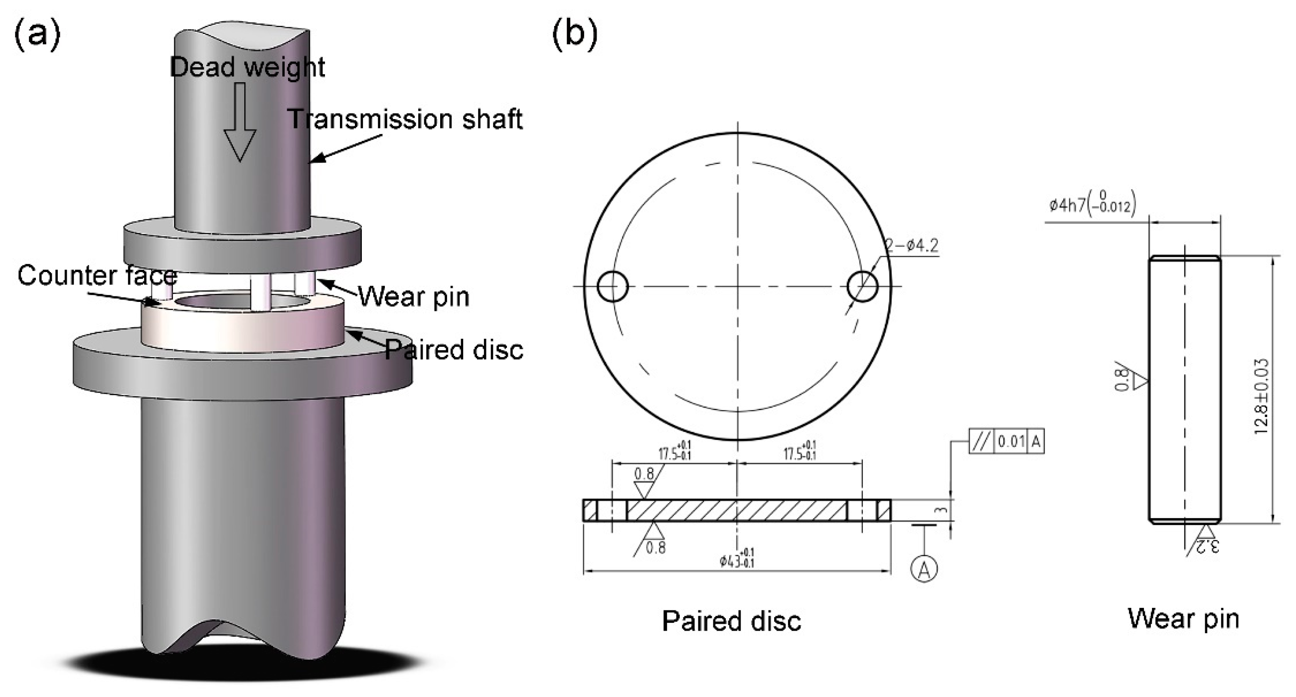
2. Materials and Methods

A schematic illustration of the surface welding process is presented in Figure 1a. Magnesium alloy wire with a diameter of 3 mm was used as the filler material, which was prepared by ingot casting, extrusion, and drawing. As-cast magnesium alloy sheets with a thickness of 10 mm were used as the welding base. Chemical compositions of the welding wire and the welding substrate are summarized in Table 1. To remove impurities and the oxide layer on the surface of the welding wire and the welding substrate, the surfaces were mechanically polished then cleaned with an organic solvent. Surface welding of the magnesium alloy sheet surface was performed using tungsten inert gas welding (Invertec V160-T, Lincoln Electric Company, Cleveland, The United States). The welding voltage was 15 V and the welding current was 130 A. The shielding gas was argon (99.99% purity) with a flow rate of 16 L/min. After surfacing, the size of the sample was approximately φ = 20 mm × 30 mm. Linear cutting was used to produce surface-welded samples and the samples were mechanically polished along the longitudinal plane. Then, the polished surfaces were corroded with mixed acid (5 g picric acid, 5 mL acetic acid, 12 mL water, and 80 mL alcohol). The microstructures of the samples were observed using optical microscopy (OM; DMI5000M, Leica Microsystems, Weitzlar, Germany) and scanning electron microscopy (SEM; SSX-550, Shimadzu, Kyoto, Japan) with energy dispersive spectroscopy (EDS). The phase compositions of surface-welded alloys with various concentrations of Gd were analyzed by X-ray diffractometry (XRD; Empyrean, PANalytical, Alemlo, Netherlands). The accelerating voltage was 40 kV and the current was 40 mA. The XRD data were fitted and quantitatively analyzed using the Rietveld method to calculate the volume percentage of each phase [14,15]. Hardness of samples were tested using a macro hardness tester (452 SVD, Wolpert, Norwood, the United States). Each sample was tested five times and the average was taken as the final hardness.
The friction and wear experiments were carried out on a vertical universal friction and wear testing machine (MMU-5G, Shandong Baohang Machine Equipment Manufacturing Co., Ltd., Jinan, China), as shown in Figure 2a. The load ranged from 15–120 N and the sliding speed was 0.75 m/s. The sliding distance was 1.5 km and the ambient temperature was 25 °C. The pin-on-disc test was conducted with a φ = 4 mm × 12.8 mm friction pin. The paired disc was made of ASTM1045 steel with about 45 HRC. To avoid the influence of uneven microstructural distribution of the samples on the experimental results, the friction pins were cut from the center of the samples (Figure 1b). The detailed shape parameters of the disc and wear pin are shown in Figure 2b. To ensure dimensional accuracy, the pins and disks were machined using a high-precision vertical computer numerical control (CNC) milling machine (VMC850B; Yunnan CY Group Co., Ltd., Kunming, China). To ensure full contact between the pin and the disc, the same parameters were used to pre-grind the surface of the samples for 1 min before the test. At the end of the test, the mass of the friction pin was measured using an electronic analytical balance (FA2104, SOPTOP, Shanghai, China). The average of three measurements of each sample was taken as the final weight. The ratio of mass loss to density of the magnesium alloy was used to calculate the wear volume. In addition, the wear rate per unit distance was calculated by dividing the wear volume by the sliding distance (mm3/m). After the experiment, the morphologies of the wear surface and debris were observed using SEM and the wear mechanism was analyzed. The friction pin was cut parallel to the sliding direction and the microstructure of the subsurface layer was observed using OM. Friction-induced deformation of the subsurface layer of the alloy was analyzed.

3. Results

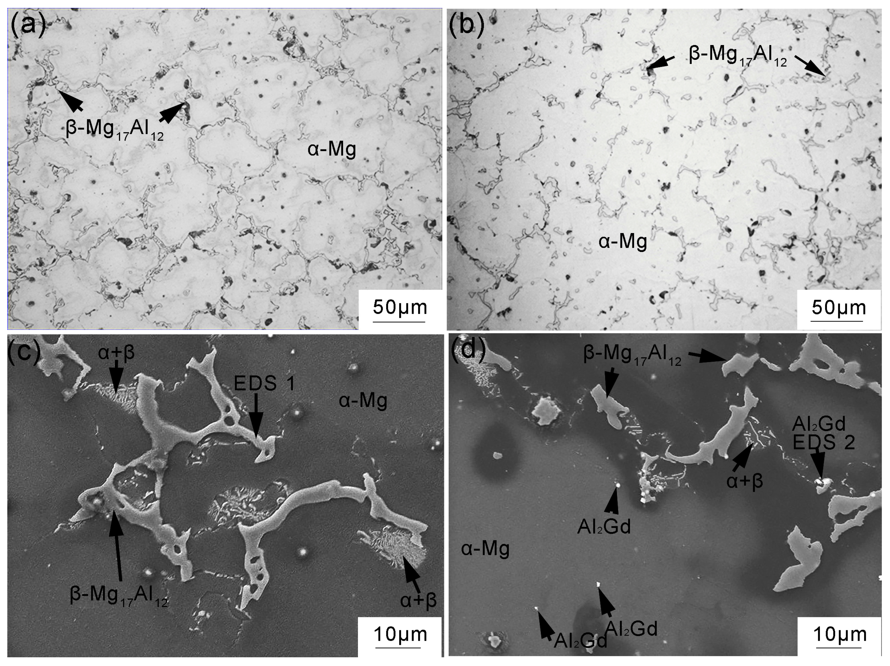
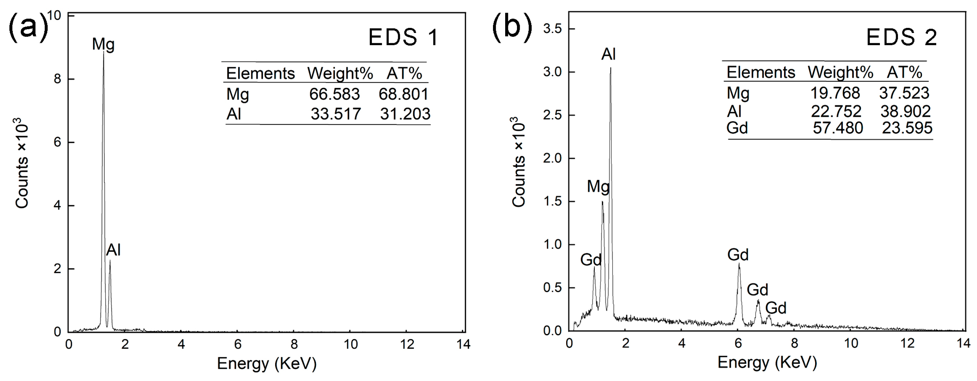
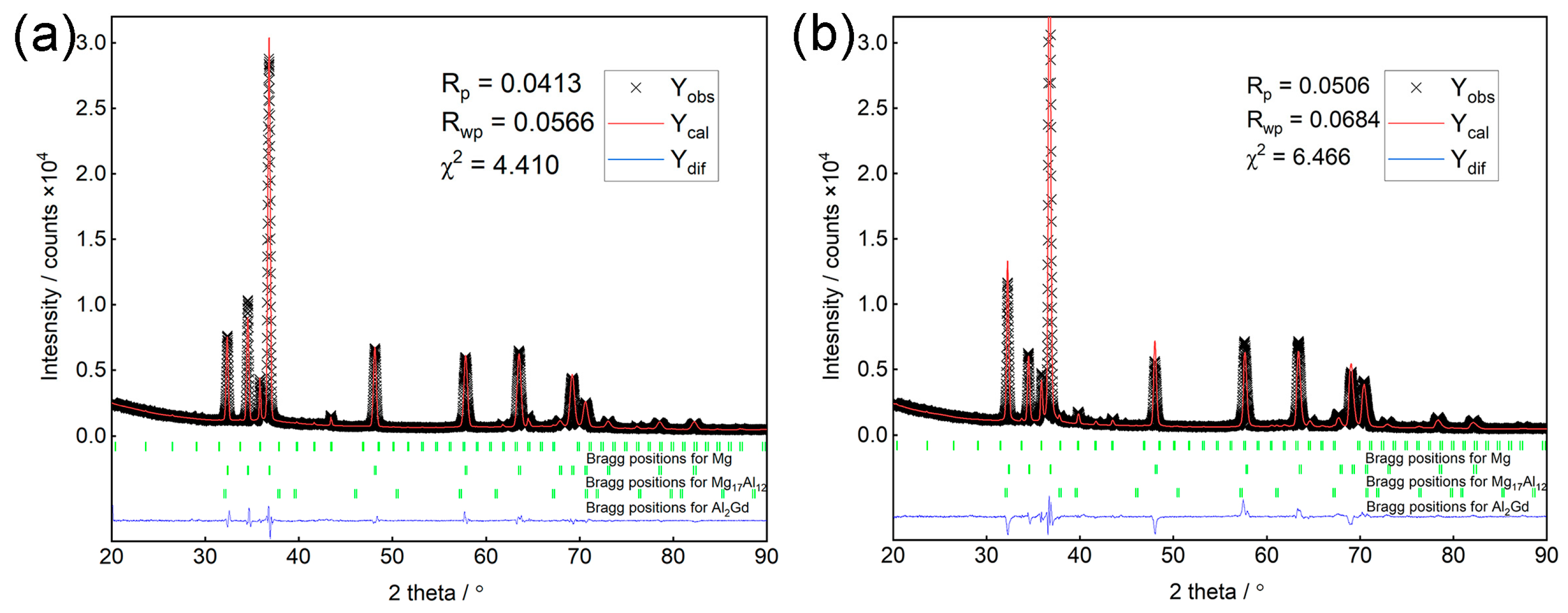
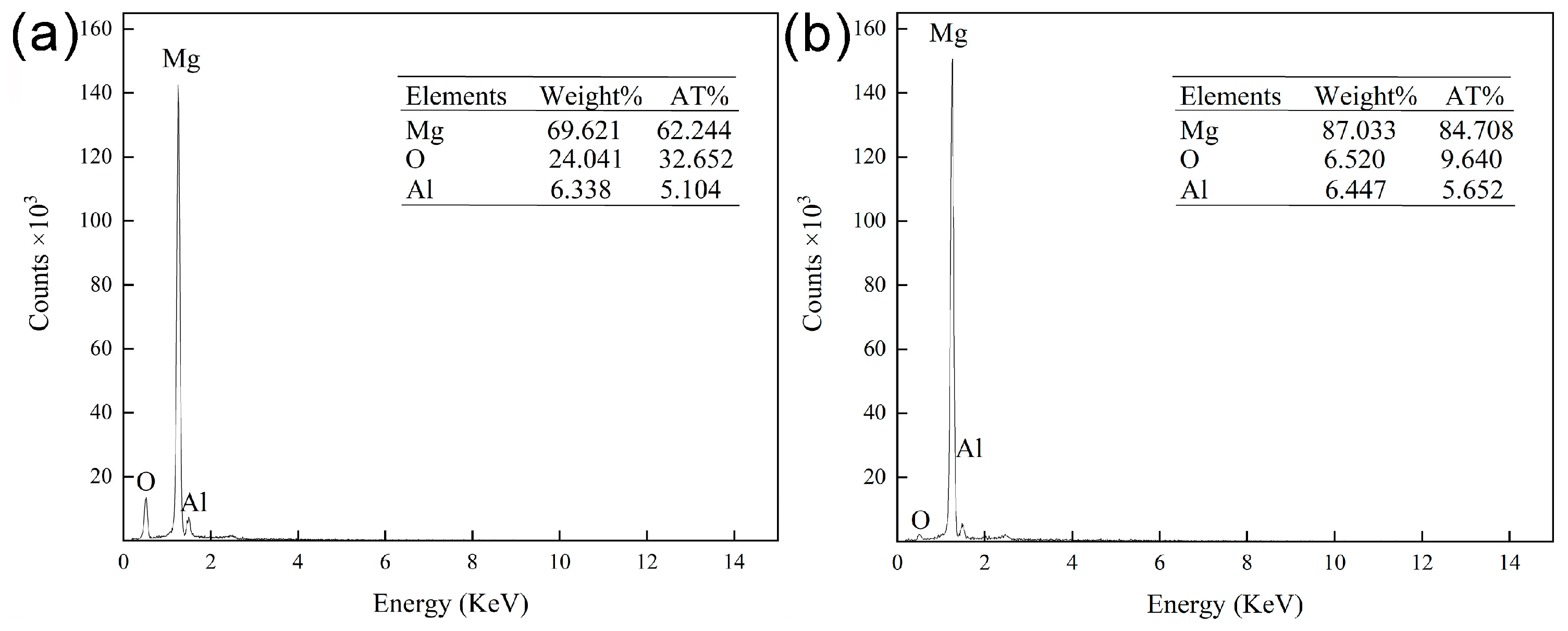
3.1. Microstructure of Surfacing Magnesium Alloy

The microstructures of surfacing AZ91 magnesium alloys with and without Gd are shown in Figure 3. Figure 3a,c show that the microstructure of the surfacing AZ91 alloy is composed of α-Mg matrix and coarse net-like β-Mg17Al12 phase, which precipitate in the form of a divorced eutectic structure at grain boundaries. A small amount of α-Mg can be observed in the pores of the β-phase. A large quantity of lamellar eutectic structures with alternating α-Mg and β-Mg17Al12 adhere to the edges of the β-phase. Optical microstructures of the alloy with 0.5% Gd are shown in Figure 3b, respectively. With the addition of Gd, the amount of β phase decreases significantly and separates from the network to form irregular strips and blocks. The SEM (Figure 3d) and EDS (Figure 4) results show that the Gd is mainly distributed throughout the magnesium matrix in the form of fine spherical Al–Gd phases with a diameter of approximately 1 μm.
The XRD analysis results and fitted curves obtained using the Rietveld method are presented in Figure 5. The quantitative phase analysis results are summarized in Table 2. Without Gd, the surfacing alloy is mainly composed of two phases: α-Mg and β-Mg17Al12. The volume percentage of β-phase is approximately 5.7%. When 0.5% Gd is added, Gd and Al atoms combine to form Al2Gd phases with a volume fraction of about 0.5%, which reduces the volume percentage of β-phase to 4.5%.

3.2. Tribological Behavior of Surfacing Magnesium Alloys

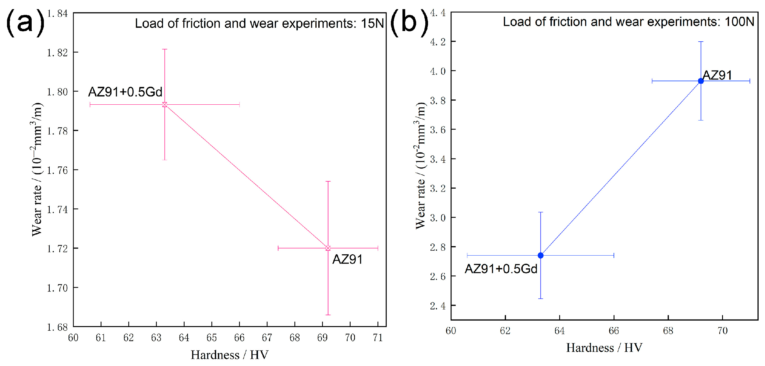
3.2.1. Wear Rate and Friction Coefficient

A relatively large experimental load of 120 N generated obvious jitter in the experimental equipment, which affected data accuracy. Therefore, only data for loads between 15–100 N were retained, as shown in Figure 6. For loads from 15 to 60 N, the wear rate of the surfacing AZ91 alloy without Gd gradually increased linearly with the increasing load. When the load reached 100 N, the wear rate of the AZ91 alloy increased sharply, approaching 1.5 times 60 N, indicating transition from a stable mildly worn state to an unstable severely worn state. With 0.5% Gd, the wear rate of the alloy increased slightly under the 15 N load. However, within the range of 30–100 N, the wear rate of the AZ91 + Gd alloy was significantly lower compared to the AZ91 alloy. In addition, as the load increased, the wear rate of the surfacing AZ91 + Gd alloy showed a trend of stable, linear growth within the scope of the experiment and no obvious inflection point. Friction coefficients of the two alloys with and without the addition of the RE element are shown in Figure 6b. When the normal load was 15 N, the friction coefficients of both alloys was around 0.4. Moreover, as the experimental load increased, the friction coefficients of the surfacing alloys exhibited a gradual downward trend.

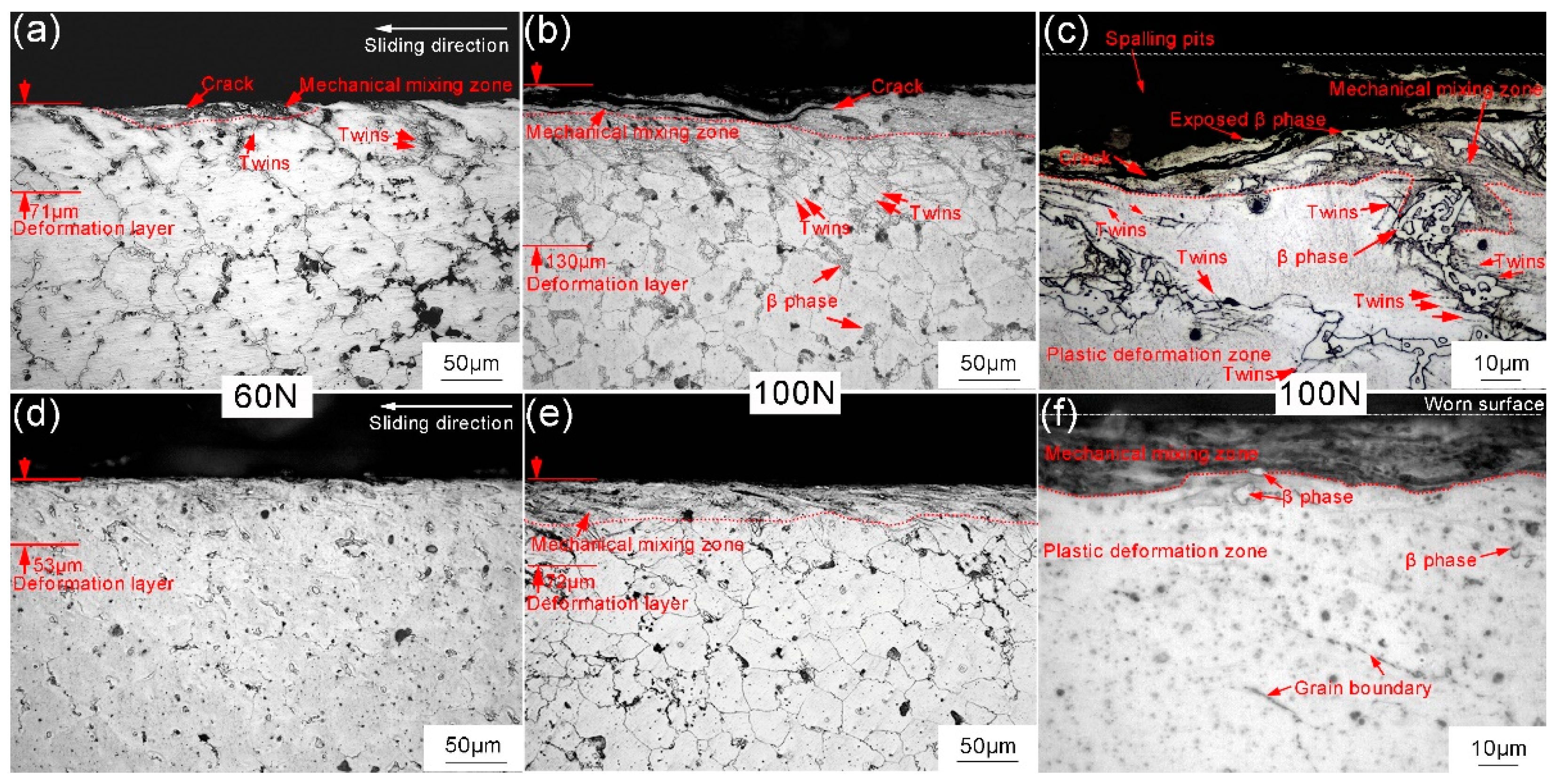
3.2.2. Wear Mechanism

The influence of tribological parameters on the wear resistance of magnesium alloys is mainly related to changes in the wear mechanism. To determine the wear mechanisms of the surfacing magnesium alloys under different experimental loads, the wear surface and wear debris morphologies were analyzed with SEM. Four wear mechanisms were observed, as shown in Figure 7: abrasive wear, oxidative wear, delamination wear, and severe plastic deformation. For a load of 15 N, many grooves and scratches were observed parallel to the sliding direction on the surface of the surfacing AZ91 alloy (Figure 7a), which are the main features of abrasive wear. Hard-microscopic protrusions generated on the surface of the friction material and shedding of abrasive particles during the friction process can have a violent cutting and plowing effect on the alloy. It is worth noting that under this low load, scratches on the surface of the AZ91 alloy were relatively shallow compared with those on the AZ91 + Gd alloy (Figure 7d). In addition, discontinuities were found in some positions, indicating a relatively small amount of abrasive wear. The element content was analyzed by EDS and the results are shown in Figure 8a. The surface of the alloy contained a large amount of oxygen (O), indicating significant oxidative wear. When the normal load was increased to 60 N, short cracks perpendicular to the slip direction appeared on the surface of the surfacing AZ91 alloy, as well as relatively large spalling pits (Figure 7b), which are the main features of delamination wear. When the load was increased to 100 N, the degree of delamination on the surface of the magnesium alloy significantly increased and serious plastic deformation occurred. Through the plastic deformation mechanism, scratches and grooves on the worn surface disappeared and were replaced by a large smooth area (Figure 7c). At the same time, metal on the surface was gradually extruded from the metal edge and a layered structure formed at the edge of the sample (Figure 9a). A large amount of flake-like wear debris was also observed (Figure 9c). These morphological changes indicate that under a 100 N load, the wear mechanism was dominated by severe plastic deformation and delamination wear. Changes in the wear mechanism normally indicate that the metal has entered the severe wear state, which is consistent with changes in the wear rate described above (Figure 6). Furthermore, the results of the EDS analysis show that the O content in the worn surface was extremely low under the load of 100 N, suggesting almost no oxidative wear (Figure 8b).
Under different loads, the effect of Gd addition on the wear mechanism of the alloy varied slightly. When a load of 15 N was applied, the scratches and furrows that appeared on the wear surface of the AZ91 + Gd alloy were deeper and straighter (Figure 7d) than those observed on the AZ91 alloy. This suggests that there was a greater degree of abrasive wear for the AZ91 alloy. However, under the same 60 N load, although the AZ91 alloy underwent severe delamination wear, the wear mechanism of the AZ91 + Gd alloy was still dominated by abrasive wear, as shown in Figure 7e. Increasing the load to 100 N slightly increased the degree of delamination wear of the AZ91 + 0.5 Gd alloy, but not to more than that of the AZ91 alloy, as shown in Figure 7f. Meanwhile, it can be seen from the edge morphologies and wear debris morphologies in Figure 9 that severe plastic deformation had a much smaller impact on the AZ91 + Gd alloy than on the AZ91 alloy. Under the 100 N load, the wear process of the surfacing alloy containing Gd was dominated by two mechanisms: abrasive wear and delamination wear. Whereas severe plastic deformation only had a minor impact.

3.2.3. Effect of Friction on Deformation Behavior of the Subsurface Layer

During the friction and wear processes, energy dissipation and material loss mainly occur in the surface and subsurface layers of frictional contact areas. Understanding changes in the microstructure of the subsurface layer during friction-induced deformation is fundamental to understanding the wear mechanism of the surfacing magnesium alloy. Microstructures of the subsurface layers of alloys with different Gd contents and under different loads were characterized, as shown in Figure 10. When the load was 60 N, the shear stress generated by frictional contact caused obvious plastic deformation of the surfacing AZ91 alloy. The thickness of the deformed layer was approximately 71 μm (Figure 10a). As the load was increased to 100 N, the amount of subsurface layer deformation increased significantly, and the thickness of the deformed layer increased to about 130 μm (Figure 10b). Depending on the amount of deformation, the subsurface layer of the AZ91 alloy can be divided into two distinct areas: mechanical mixing zone (about 0–45 μm from the surface) and plastic deformation zone (about 45–130 μm from the surface). High-density twins were observed in the plastic deformation zone. Most of the twin lines were generated at the interface between the β-phase and the α-Mg matrix, as well as at grain boundaries and expanding into the grains, as shown in Figure 10b,c. In the mechanical mixing zone, the metal underwent severe plastic deformation and some mechanical agitation under the action of the shearing force. The large amount of β-phase was shifted towards the sliding direction, resulting in large deformation of the surrounding matrix. Related literature has also indicated that metal in the mechanical mixing zone undergoes dynamic recrystallization under the combined action of frictional stress and frictional heat [16,17]. In addition, cracks spreading to the surface and spalling pits can be observed in Figure 10b. When spalling pits form, metal located in the mechanical mixing zone falls off and becomes wear debris. This exposes the metal to a relatively low degree of deformation in the plastic deformation zone and bulk Mg17Al12 phase. In subsequent friction processes, the bulk Mg17Al12 phase may detach and hinder relative sliding between the magnesium alloy and the friction disc resulting in three-body abrasive wear. The addition of Gd significantly decreased the thickness of the deformed layer, as shown in Figure 10d–f. Due to the reduced amount of coarse β-phase, the number and density of twinning lines were also significantly decreased, indicating less plastic deformation occurred in the alloy subsurface layer. Meanwhile, almost no pits formed by cracks and spalling were observed in the subsurface layer of the surfacing AZ91 + Gd alloy. Therefore, the distribution in the mechanical mixing zone was relatively continuous.

3.3. Macro Hardness of Surfacing Magnesium Alloys

In most wear models, hardness of the material has a significant influence on wear resistance [18,19,20]. Hardness values of the four alloys were measured. The results are presented in Table 3. The surfacing AZ91 alloy without Gd has the highest macroscopic hardness value of 69.2 HV. After adding Gd, the hardness of the surfacing alloy decreased to 63.3 HV.
The relationship between hardness and wear rate of the surfacing-welding magnesium alloys under different friction loads is shown in Figure 11. When the experimental load was 15 N, higher hardness was associated with a lower wear rate and better wear resistance. However, when the 100 N load was applied, the relationship between hardness and wear rate was no longer linear. Although the hardness of surfacing AZ91 alloy was highest, the wear resistance was poorest under the 100 N load.

4. Discussion

4.1. Influence of Load on the Wear Mechanism of Surfacing Magnesium Alloys

From Section 3.2.2, four wear mechanisms in the surfacing AZ91 magnesium alloy can be defined: oxidative wear, abrasive wear, delamination wear, and severe plastic deformation. Under the low load (15 N), the main wear mechanism was abrasive wear, followed by oxidative wear; under medium loads (30–60 N), the main wear mechanisms were abrasive wear and delamination wear; under the high load (100 N), the main wear mechanisms became delamination wear and severe plastic deformation. The wear mechanisms and wear distributions observed in our study are consistent with those previously observed in as-cast Mg-Al alloys [17,21,22].

4.1.1. Influence of Load on Oxidative Wear Mechanism

Oxidative wear is a common wear mechanism of magnesium alloys during friction processes because magnesium alloys are easily oxidized. An oxidation layer quickly forms in the contact gap as surface metal is rapidly oxidized under the action of frictional heat in the presence of oxygen [23]. The oxide layer begins to break and peel off under the action of microscopic convex plowing, and a new oxide layer forms on the newly exposed surface. Repetition of this process leads to wear. Three conditions are required for oxidative wear: (1) The oxidation rate of the friction surface must be larger than the rate at which the oxide layer is worn; (2) The thickness of the oxide layer must be larger than the depth of surface wear damage; (3) The strength of the bond between the oxide layer and the substrate must be higher than the shear stress on the friction surface [24,25]. In our experiment, oxidative wear mainly occurred under the low and medium load conditions. When the load is relatively high, the contact surface gap is rapidly compressed, leading to less interaction between the magnesium alloy and oxygen and the rate and degree of oxidation decreases. Delamination wear and severe plastic deformation lead to a rapid increase in surface wear, which exceeds the rate of formation of the oxide layer. In addition, the relatively high normal load rapidly increases shear stress on the metal surface, which can be much higher than the strength of the bond between the oxide layer and the substrate. Therefore, high loads do not facilitate oxidative wear and only a small amount of O content can be detected on the worn surface (Figure 8).

4.1.2. Influence of Load on Abrasive Wear Mechanism

Under medium and low loads, abrasive wear is the most important wear mechanism. To estimate the contribution of abrasive wear to the wear rate of the surfacing alloys, two simple scenarios were considered: contact of conical hard micro-protrusions with pure Mg matrix (Figure 12a) and contact of conical hard micro-protrusions with hard β-phase (Figure 12b).
When the hard, cone-shaped micro-protrusions are in contact with a pure magnesium matrix, as shown in Figure 12a, the cone is pressed into the softer magnesium under the action of normal force F N . The projected area of the cone on the vertical plane is S 0 and the volume d V 0 plowed off after the cone is displaced by d x is
d V 0 = S 0 d x = r 0 h d x = r 0 2 tan θ d x
where r 0 is the diameter of the cone embedded in the α-Mg matrix. This volume is approximately equal to the volume of debris produced by abrasive wear. According to the definition of hardness H 0 , we obtain
r 0 2 = Δ F N H 0 π
In this paper, the volume of material loss per unit sliding length is used as the wear rate, so wear rate W 0 is
W 0 = d V 0 d x = r 0 2 tan θ = tan θ H 0 π Δ F N
In addition to magnesium matrix, the surfacing AZ91 alloy also contains many net-like β-phases. A nanoindentation experiment conducted by Gupta et al. [26] showed that the hardness of the β-phase is about four-times that of the magnesium matrix, 3.8 ± 0.3 GPa versus 1.4 ± 0.1 GPa, respectively. Therefore, during the wear process, coarse hard net-like β-phases can effectively prevent hard microscopic protrusions from being pressed into the matrix. This can protect the matrix to a certain extent, as shown in Figure 12b. The volume of debris produced by the plowing action is
d V 1 = r 1 2 tan θ d x
For the situation depicted in Figure 12b, the wear rate W 1 is
W 1 = d V 1 d x = r 1 2 tan θ = tan θ H 1 π Δ F N
where tan θ ¯ and Δ F N ¯ are the weighted averages of tan θ and Δ F N of all micro-contacts, respectively; constant k is defined as the area occupied by the β-phase. Then, the total wear rate is
W = ( 1 k ) W 0 + k W 1 = ( 1 k ) tan θ ¯ H 0 π Δ F N ¯ + k tan θ ¯ H 1 π Δ F N ¯ = Δ F N ¯ · tan θ ¯ π ( 1 k H 0 + k H 1 )
Thus, for surfacing AZ91 alloy, the wear rate is W Δ F N ¯ . According to the microscopic contact model proposed by Zhao et al. [27], Δ F N ¯ is approximately proportional to the applied normal load F N . Therefore, the total wear rate W is approximately proportional to the normal load F N . This is the main reason the wear rate of the surfacing AZ91 alloy increases approximately linearly in the range 15–60 N (Figure 6).

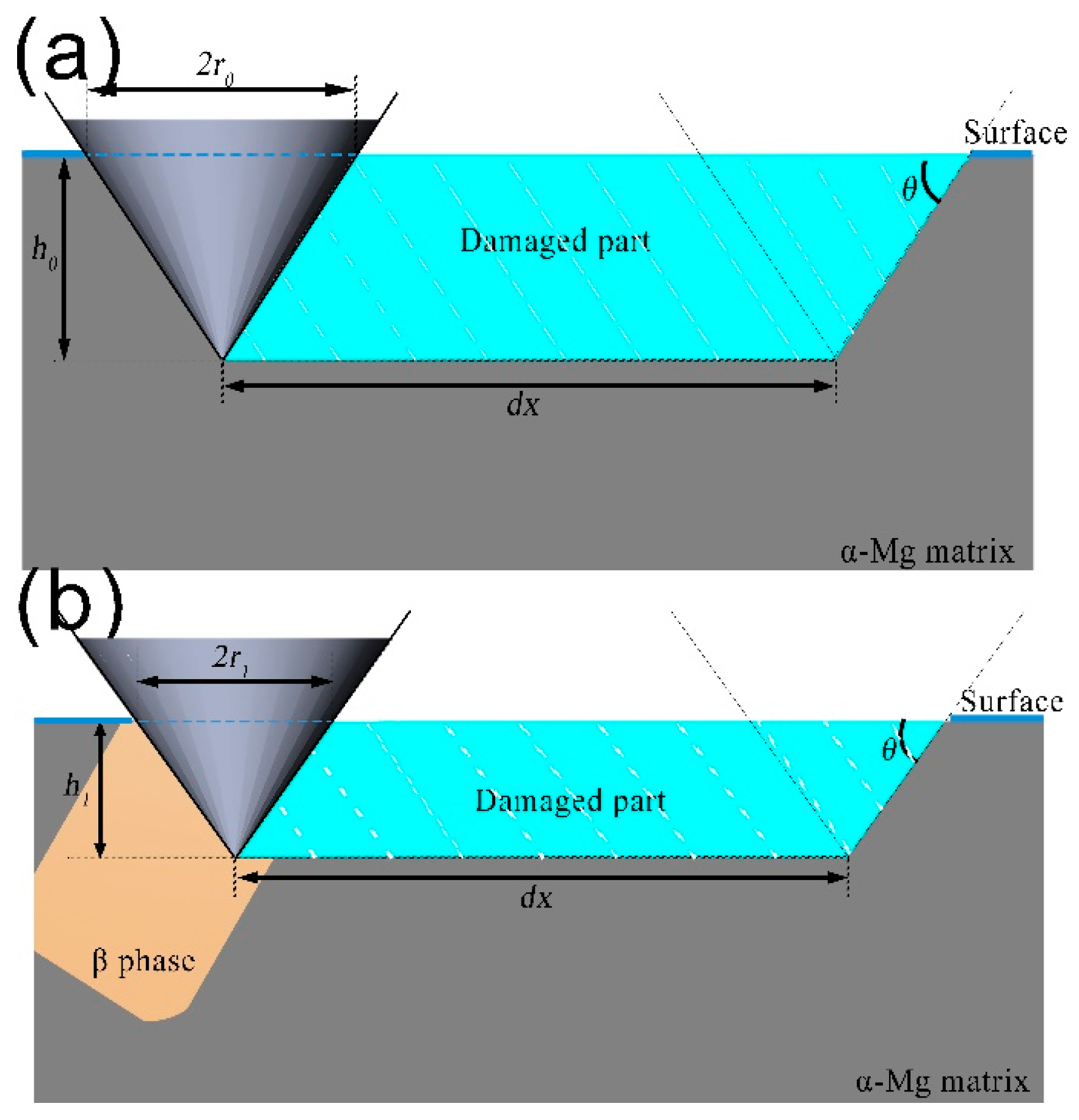
4.1.3. Influence of Load on Delamination Wear Mechanism

In this experiment, the delamination wear mechanism appeared in the load range 30–100 N. When the experimental load is higher than 30 N, normal stress and shear stress generated by frictional contact will continue to cyclically act on the surface metal of the magnesium alloy as the sliding process continues. This eventually causes surface and subsurface areas close to the contact surface to undergo significant plastic deformation and even, mechanical flow, as shown in Figure 13a,c. According to Hertz contact theory, maximum shear stress occurs at a certain depth below the surface, where deformation behavior induces many dislocations and other defects [28]. As the surfacing AZ91 alloy contains a large quantity of sizeable and irregular β-phases, defects such as dislocations easily accumulate, resulting in stress concentrations. Relevant studies on the localized strain behavior of magnesium alloys have shown that dislocation plugging occurs during the deformation process due to differences in the degree of deformation of β-phase and matrix. This increases the strain incompatibility between matrix grains and β-phase, which can initiate twinning between β-phase and α-Mg matrix at the interface [29], as shown in Figure 13a. Therefore, within the metallographic structure of the subsurface layer of the alloys after friction, many twins are observed around the β phase (Figure 10a,b). However, as the friction test progresses, the degree of deformation continues to increase. Once the critical value is exceeded, the accumulated energy is released in the form of holes and microcracks at the interface between the matrix and β-phase. Microcracks continue to be initiated and expand, eventually intersecting with or extending to the surface (Figure 13c). Peeling of large areas of surface metal occurs. Cracks and spalling pits unique to the delamination wear mechanism are formed (Figure 7). An increase in the normal load rapidly increases the normal stress and shear stress induced by the frictional contact. Finally, the degree of plastic deformation of the subsurface metal is further increased (Figure 10), which ultimately, increases the degree of delamination wear (Figure 7b,c).

4.1.4. Influence of Load on Severe Plastic Deformation Mechanism

When the normal load is increased to 100 N, the microscopic contact area between the friction pair and the heat generated by friction both rapidly increase [27,30]. Thermal softening or even partial melting of the surface layer of the surfacing AZ91 alloy occur. Normal and shear stresses are generated, causing severe plastic deformation in the sliding direction (Figure 10). Metal is gradually squeezed out at the metal edge (Figure 9). Severe plastic deformation further increases the degree of delamination wear, causing severe flaking on the surface (Figure 7c). Finally, the quality of the surfacing AZ91 alloy is quickly degraded under the combined action of delamination wear and severe plastic deformation. The alloy enters the severe wear stage, and the wear rate rapidly increases (Figure 6).

4.2. Effect of Gd Addition on the Wear Mechanism of Surfacing Magnesium Alloys

The Archard model is a wear model frequently adopted in the literature [19]. According to the model, a higher material hardness increases wear resistance, according to the formula W = K · F N / H . This law has been verified by numerous experiments. In the present study, the addition of Gd was found to decrease the hardness of the surfacing Mg-Al-Zn alloy while improving its wear resistance under medium and high loads (Figure 6 and Figure 11), which does not conform to the Archard model. Friction and wear are extremely complex processes, and the important influencing factors are incorporated in the wear coefficient K , except for load F N , sliding distance L , and hardness σ of the softer material. Wear coefficient K is uncertain and highly variable, and its true meaning has not yet been determined. The only certainty is that wear coefficient K contains information about the probability of wear debris breaking away from the tribological system and the size distribution of wear debris. The addition of RE elements changes the wear coefficient K while altering the hardness H of the surfacing magnesium alloy. In addition, varying the load changes the wear mechanism, which also affects the wear coefficient K . Therefore, under different normal loads, the Archard formula cannot be directly applied. The influence of the addition of the RE element on the wear resistance of the surfacing magnesium alloy must be analyzed according to the type of wear.

4.2.1. Effect of Gd Addition on Oxidative Wear Mechanism

Numerous theoretical models have been proposed to describe the oxidative wear process of metals [31,32]. Although the morphologies and formation mechanisms of the oxide layer are not the same for different materials and different operating conditions, the models have one thing in common: they assume that the oxide layer plays a decisive role in oxidative wear. The thick and dense oxide layer inhibits direct contact between the two metals, which plays a protective role. Quinn derived a mathematical model of oxidative wear under slight wear [33], expressed as
W = A e x p ( Q / R T ) ρ 2 v ξ 2 · d Δ F N σ s
where A is the Arrhenius constant, Q is the activation energy of the oxidation reaction, R is the universal gas constant, T is the contact temperature of the asperity surface, ρ is the oxide layer density, v is the sliding velocity, ξ is the maximum thickness of the oxide layer that the metal matrix can withstand, d is the distance moved by the microwear contact point, and σ s is the yield strength of the material. The formula shows that the wear rate is inversely proportional to the square of the oxide layer thickness and density. The higher the thickness and density of the oxide layer, the lower the wear rate. However, it is well known that the oxide layer formed by the oxidation of magnesium is loose and porous and can easily break off [34]. Although the tribochemical reaction may increase the density of the oxide layer, it remains unknown whether the magnesium alloy oxide layer can continue to grow, accumulate, and be compacted to provide sufficient protection during the friction process. On the other hand, many studies on the oxidation behavior of the RE magnesium alloys show that the oxidation products of RE elements including Gd and yttrium (Y), such as Gd2O3, increase the thickness and density of the oxide layer. The RE elements not only form an additional dense oxide layer but also fill in the gaps of MgO [35,36]. According to Equation (7), an increase in density ρ and thickness ξ can reduce the wear rate of the surfacing alloy, thereby improving the oxidative wear resistance of the alloy.

4.2.2. Effect of Gd Addition on Abrasive Wear Mechanism

After the addition of Gd, the β-phase content decreases greatly. Area k occupied by the second phase in Equation (6) is no longer a constant and the equation can be rewritten as
W = k ( 1 H 0 1 H 1 ) Δ F N ¯ · tan θ ¯ π + Δ F N ¯ · tan θ ¯ H 0 π
Since 1 H 0 1 H 1 > 0 , when the experimental load is constant, Δ F N ¯ can be regarded as a constant. Thus, Equation (8) can be simplified as
W = a k + b
That is, the wear rate is inversely proportional to the percentage of β-phase in the worn surface. The results of the quantitative XRD analysis show that the addition of Gd decreases the β-phase content (Table 2), which decreases the area k of the wear surface occupied by β-phase during the friction process. This weakens the protective effect of the net-like β-phase to the relatively soft magnesium matrix and improves the abrasive wear rate W . For surfacing magnesium alloys, although the analysis in Section 4.2.1 suggests that the addition of RE elements can improve the oxidative wear resistance of the alloy, under a load of 15 N, the contribution of oxidative wear to the overall wear is small. The main wear mechanism is abrasive wear. Therefore, the addition of Gd ultimately increases the wear rate of the alloy (Figure 2).

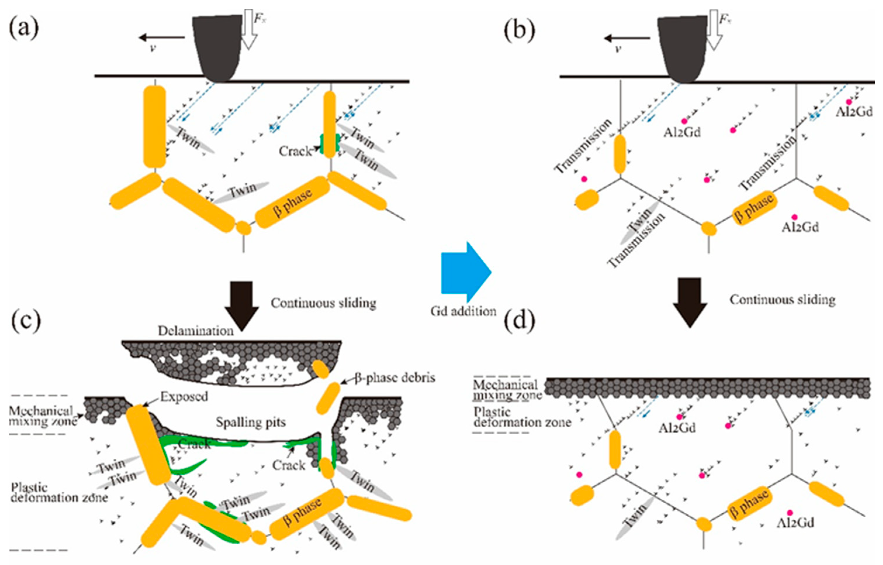
4.2.3. Effect of Gd Addition on Delamination Wear Mechanism

From the analysis in Section 4.1.3, it can be seen that coarse β-phase in the surfacing alloy easily generates stress concentrations during friction-induced subsurface plastic deformation, thereby increasing the degree of delamination wear. With the addition of Gd, the size and quantity of the coarse and irregularly shaped β-phases are significantly reduced (Figure 3). Thus, the number of stress concentrations in the surface of the metal decreases, as shown in Figure 13. However, related studies [37,38] have suggested that the addition of Gd leads to the formation of a high-temperature-resistant Al2Gd phase in the alloy with much higher thermal stability than the Mg17Al12 phase. In the process of sliding, the Al2Gd phase may block the dislocation movement and have a strengthening effect. As a result, the thickness and degree of plastic deformation of the plastic deformation layer of AZ91 + Gd alloy are significantly lower than those of AZ91 alloy after sliding friction (Figure 10). The addition of Gd decreases the negative effects of delamination wear on the wear resistance of the alloy. In addition, during the delamination wear process of the surfacing AZ91 alloy, bulk β-phases with much higher hardness than the matrix hardness may peel off and become trapped between the material and the friction disc (Figure 13c). Therefore, relative sliding of the friction pair and three-body wear are hindered. This can be reduced by the addition of Gd. Thus, the addition of Gd can significantly reduce the effect of the delamination wear mechanism on the wear resistance of the surfacing magnesium alloy. Although the addition of Gd reduces the abrasive wear resistance of the surfacing alloy to a certain extent, when the load is greater than 30 N, the positive effect of Gd on delamination wear is more prominent. Eventually, the overall wear rate of the AZ91 + Gd alloy decreases.

4.2.4. Effect of Gd Addition on Severe Plastic Deformation Mechanism

When the load is increased to 100 N, differences in the deformation degree of the subsurface layer of the surfacing alloy with and without Gd become more obvious compared with the load of 60 N, (Figure 10b,e). The effect of friction on the plastic deformation behavior is clearly inhibited by the addition of the RE element. Under this load, Gd addition not only reduces the degree of delamination wear, but also effectively prevents the metal from being squeezed out at the edges due to severe plastic deformation (Figure 9). Finally, the wear rate decreases, and mild–severe wear transition of the alloy is prevented.

5. Conclusions

In this study, the wear behavior of surfacing AZ91 and AZ91 + Gd alloys were systematically analyzed using pin-on-disc sliding dry friction and wear tests. The influence of normal load and Gd addition on the wear mechanism were investigated. The main conclusions can be summarized as follows:
(1)
Within the scope of the experiment, the friction coefficient of the surfacing AZ91 alloy gradually decreased with increasing normal load and the wear rate gradually increased. The mild–severe wear transition occurred under a load of 100 N. The addition of Gd slightly increased the wear rate of the alloy under the 15 N load. The wear rate significantly decreased under loads between 30–100 N. Moreover, a mild–severe wear transition was avoided.
(2)
Four wear mechanisms can be defined for the surfacing AZ91 magnesium alloy: oxidative wear, abrasive wear, delamination wear, and severe plastic deformation. Among them, the main wear mechanism under the low load (15 N) was abrasive wear, followed by oxidative wear; under medium loads (30–60 N), the main wear mechanisms were abrasive wear and delamination wear; under the high load (100 N), the main wear mechanisms became delamination wear and severe plastic deformation.
(3)
The effect of Gd on the wear mechanism of the surfacing magnesium alloy can be mainly attributed to the evolution behavior of the subsurface microstructure during friction. Under medium and high loads (30–100 N), the addition of Gd reduces the size and amount of coarse irregular-shaped β-phase, thereby reducing the adverse effects of the delamination processes. However, the decrease in net-like β-phase also weakens the abrasive wear resistance of the alloy, which negatively affects its overall wear resistance under low loads (15 N).

Author Contributions

Conceptualization, Q.C. and C.J.; methodology, Q.C. and Y.Y.; investigation, Y.Y. and J.S.; resources, C.J.; data curation, J.S. and Y.Z.; writing (original draft preparation), Y.Y.; writing (reviewing and editing), Q.C.; supervision, J.W.; project administration, J.W.; funding acquisition, C.J. All authors have read and agreed to the published version of the manuscript.

Funding

This work was supported by the Shandong Provincial Natural Science Foundation, China (ZR2020QE161), National Natural Science Foundation of China (51975339), Youth Innovation and Technology Support Program for University in Shandong Province (2019KJB003), PhD Research Foundation of Shandong Jianzhu University (XNBS1807).

Institutional Review Board Statement

Not applicable.

Informed Consent Statement

Not applicable.

Conflicts of Interest

We declare that we do not have any commercial or associative interest that represents a conflict of interest in connection with the work submitted.

References

  1. Tolnai, D. Processing and Characterization of Magnesium-Based Materials. Crystals 2021, 11, 96. [Google Scholar] [CrossRef]
  2. Zhu, S.; Wang, Q.W.; Yin, F.L.; Liang, Y.Y.; Chen, L. Influence of Alternative Magnetic Field Frequency on Microstructure and Properties of Surfacing Welding Layer of Aluminum Alloy. Mater. Sci. Forum 2011, 697–698, 351–355. [Google Scholar] [CrossRef]
  3. Zhu, S.; Li, C.; Shen, C.D.; Liu, J. Microstructure and Micro Mechanical Property of Part Formed by GMAW Surfacing Rapid Prototyping. Key Eng. Mater. 2009, 419–420, 853–856. [Google Scholar] [CrossRef]
  4. Reisgen, U.; Oechsner, M.; Sharma, R.; Ellermeier, J.; Andersohn, G.; Engler, T.; Zokoll, E.; Heider, B.; Gonzalez Olivares, E. Influence of Preheating on Lamellar Gray Cast Iron for Surface Layer Welding applications with Plasma-Transferred Arc Powder and Metal Inert Gas Welding Processes with Duplex Steel as Filler Material. J. Therm. Spray Technol. 2020, 29, 724–740. [Google Scholar] [CrossRef] [Green Version]
  5. Vakis, A.I.; Yastrebov, V.A.; Scheibert, J.; Nicola, L.; Dini, D.; Minfray, C.; Almqvist, A.; Paggi, M.; Lee, S.; Limbert, G.; et al. Modeling and simulation in tribology across scales: An overview. Tribol. Int. 2018, 125, 169–199. [Google Scholar] [CrossRef]
  6. Li, Q.; Lu, H.; Li, D.Y. Effect of recovery treatment on the wear resistance of surface hammered AZ31 Mg alloy. Wear 2019, 426–427, 981–988. [Google Scholar] [CrossRef]
  7. Chelliah, N.M.; Kumar, R.; Singh, H.; Surappa, M.K. Microstructural evolution of die-cast and homogenized AZ91 Mg-alloys during dry sliding condition. J. Magnes. Alloy. 2017, 5, 35–40. [Google Scholar] [CrossRef]
  8. Ramesh, S.; Anne, G.; Nayaka, H.S.; Sahu, S.; Ramesh, M.R. Investigation of dry sliding wear properties of multi-directional forged Mg-Zn alloys. J. Magnes. Alloy. 2019, 7, 444–455. [Google Scholar] [CrossRef]
  9. Li, L.; Feng, J.; Liang, C.; An, J. Dry Sliding Wear Behavior and Mild-Severe Wear Transition of Mg97Zn1Y2 Alloy at Elevated Temperatures. Materials 2018, 11, 1735. [Google Scholar] [CrossRef] [Green Version]
  10. Athul, K.R.; Srinivasan, A.; Pillai, U.T.S. Investigations on the microstructure, mechanical, corrosion and wear properties of Mg-9Al-xGd (0, 0.5, 1, and 2 wt%) alloys. J. Mater. Res. 2017, 32, 3732–3743. [Google Scholar] [CrossRef]
  11. Meshinchi Asl, K.; Masoudi, A.; Khomamizadeh, F. The effect of different rare earth elements content on microstructure, mechanical and wear behavior of Mg-Al-Zn alloy. Mater. Sci. Eng. A 2010, 527, 2027–2035. [Google Scholar] [CrossRef]
  12. Zafari, A.; Ghasemi, H.M.; Mahmudi, R. An investigation on the tribological behavior of AZ91 and AZ91+3wt% RE magnesium alloys at elevated temperatures. Mater. Design 2014, 54, 544–552. [Google Scholar] [CrossRef]
  13. Chen, Q.Q.; Zhao, Z.H.; Zhu, Q.F.; Wang, G.S.; Tao, K. Cerium Addition Improved the Dry Sliding Wear Resistance of Surfacing Welding AZ91 Alloy. Materials 2018, 11, 250. [Google Scholar] [CrossRef] [PubMed] [Green Version]
  14. Rietveld, H.M. The Rietveld method. Phys. Scripta 2014, 89, 098002. [Google Scholar] [CrossRef]
  15. Toby, B.H. EXPGUI, a graphical user interface for GSAS. J. Appl. Crystallogr. 2001, 34, 210–213. [Google Scholar] [CrossRef] [Green Version]
  16. Zhang, W.; Lu, J.; Huo, W.; Zhang, Y.; Wei, Q. Microstructural evolution of AZ31 magnesium alloy subjected to sliding friction treatment. Philos. Mag. 2018, 17, 1576–1593. [Google Scholar] [CrossRef]
  17. Liang, C.; Li, C.; Lv, X.X.; An, J. Correlation between friction-induced microstructural evolution, strain hardening in subsurface and tribological properties of AZ31 magnesium alloy. Wear 2014, 312, 29–39. [Google Scholar] [CrossRef]
  18. Rupert, T.J.; Schuh, C.A. Sliding wear of nanocrystalline Ni-W: Structural evolution and the apparent breakdown of Archard scaling. ACTA Mater. 2010, 58, 4137–4148. [Google Scholar] [CrossRef]
  19. Archard, J.F.; Irst, W.H. The wear of metals under unlubricated conditions. Proc. R. Soc. Lond. Ser. A 1956, 236, 397–410. [Google Scholar]
  20. Zhang, X.; Xu, H.; Chang, W.; Xi, H.; Pei, S.; Meng, W.; Li, H.; Xu, S. A dynamic contact wear model of ball bearings without or with distributed defects. J. Mech. Eng. Sci. 2020, 24, 4827–4843. [Google Scholar] [CrossRef]
  21. Dey, A.; Pandey, K.M. Wear behaviour of Mg alloys and their composites-a review. Int. J. Mater. Res. 2018, 109, 1050–1070. [Google Scholar]
  22. Niu, X.D.; An, D.Q.; Han, X.; Sun, W.; Su, T.F.; An, J.; Li, R.G. Effects of Loading and Sliding Speed on the Dry Sliding Wear Behavior of Mg-3Al-0.4Si Magnesium Alloy. Tribol. Trans. 2017, 60, 238–248. [Google Scholar] [CrossRef]
  23. Li, L.; Feng, C.; Zhao, W.; Liang, C.; An, J. Effect of test temperature on dry sliding wear behavior and mild-severe wear transition of Mg97Zn1Y2 alloy. Mater. Res. Express 2019, 6, 46545. [Google Scholar] [CrossRef]
  24. Ilo, S.; Tomala, A.; Badisch, E. Oxidative wear kinetics in unlubricated steel sliding contact. Tribol. Int. 2011, 44, 1208–1215. [Google Scholar] [CrossRef]
  25. Garbar, I.I. Gradation of oxidational wear of metals. Tribol. Int. 2002, 35, 749–755. [Google Scholar] [CrossRef]
  26. Gupta, N.; Luong, D.D.; Rohatgi, P.K. A method for intermediate strain rate compression testing and study of compressive failure mechanism of Mg-Al-Zn alloy. J. Appl. Phys. 2011, 109, 103512. [Google Scholar] [CrossRef]
  27. Zhao, Y.; Maietta, D.M.; Chang, L. An Asperity Microcontact Model Incorporating the Transition from Elastic Deformation to Fully Plastic Flow. J. Tribol. 2000, 122, 86–93. [Google Scholar] [CrossRef]
  28. Machado, M.; Moreira, P.; Flores, P.; Lankarani, H.M. Compliant contact force models in multibody dynamics: Evolution of the Hertz contact theory. Mech. Mach. Theory 2012, 53, 99–121. [Google Scholar] [CrossRef]
  29. Koike, J.; Sato, Y.; Ando, D. Origin of the Anomalous {10–12} Twinning during Tensile Deformation of Mg Alloy Sheet. Mater. Trans. 2008, 49, 2792–2800. [Google Scholar] [CrossRef] [Green Version]
  30. An, J.; Li, R.G.; Lu, Y.; Chen, C.M.; Xu, Y.; Chen, X.; Wang, L.M. Dry sliding wear behavior of magnesium alloys. Wear 2008, 265, 97–104. [Google Scholar] [CrossRef]
  31. Quinn, T.F.J. The oxidational wear of low alloy steels. Tribol. Int. 2002, 35, 691–715. [Google Scholar] [CrossRef]
  32. Wilson, J.E.; Stott, F.H.; Wood, G.C. The development of wear-protective oxides and their influence on sliding friction. Proc. R. Soc. Lond. A Math. Phys. Sci. 1997, 369, 557–574. [Google Scholar]
  33. Quinn, T.F.J. The Effect of "Hot-Spot" Temperatures on the Unlubricated Wear of Steel. ASLE Trans. 1967, 10, 158–168. [Google Scholar] [CrossRef]
  34. Tan, Q.; Atrens, A.; Mo, N.; Zhang, M. Oxidation of magnesium alloys at elevated temperatures in air: A review. Corros. Sci. 2016, 112, 734–759. [Google Scholar] [CrossRef] [Green Version]
  35. Tan, Q.; Yin, Y.; Mo, N.; Zhang, M.; Atrens, A. Recent understanding of the oxidation and burning of magnesium alloys. Surf. Innov. 2019, 7, 71–92. [Google Scholar] [CrossRef]
  36. Czerwinski, F. The reactive element effect on high-temperature oxidation of magnesium. Int. Mater. Rev. 2015, 60, 264–296. [Google Scholar] [CrossRef]
  37. Min, X.G.; Du, W.W.; Xue, F. Analysis of EET on Ca increasing the melting point of Mg17Al12 phase. Chin. Sci. Bull. 2002, 47, 1082–1084. [Google Scholar] [CrossRef]
  38. Ashrafizadeh, S.M.; Mahmudi, R. Effects of Gd, Y, and La Rare-Earth Elements on the Microstructural Stability and Elevated-Temperature Mechanical Properties of AZ81 Magnesium Alloy. Metall. Mater. Trans. A 2019, 50, 5957–5968. [Google Scholar] [CrossRef]
Figure 1. Schematic diagrams of (a) surface welding process and (b) sampling location.
Crystals 11 00554 g001
Figure 2. Schematic representation of experimental setup: (a) pin-on-disc configuration, (b) surface topography parameters of disc and pin surfaces.
Crystals 11 00554 g002
Figure 3. Microstructures of surfacing magnesium alloys: (a,c) AZ91 alloy, (b,d) AZ91 + 0.5 Gd alloy.
Crystals 11 00554 g003
Figure 4. Results of EDS analysis performed at: (a) arrow 1 in Figure 3a, (b) arrow 2 in Figure 3d.
Crystals 11 00554 g004
Figure 5. X-ray diffractograms of surfacing alloys: (a) AZ91 alloy, (b) AZ91 + 0.5 Gd alloy.
Crystals 11 00554 g005
Figure 6. Results of friction and wear tests of surfacing magnesium alloys under different loads: (a) wear rate, (b) friction coefficient.
Crystals 11 00554 g006
Figure 7. Worn surface morphology of surfacing magnesium alloys: (ac) AZ91 alloy, (df) AZ91 + 0.5 Gd alloy. The sliding direction is from top to bottom.
Crystals 11 00554 g007
Figure 8. Results of EDS analysis of surfaces performed at: (a) arrow 1 in Figure 7a, (b) arrow 2 in Figure 7c.
Crystals 11 00554 g008
Figure 9. Wear edge morphology and debris morphology of surfacing magnesium alloys under a 100 N load: (a,c) AZ91 alloy, (b,d) AZ91 + 0.5 Gd alloy.
Crystals 11 00554 g009
Figure 10. Microstructure of subsurface layers of surfacing magnesium alloys after friction and wear: (ac) AZ91 alloy, (df) AZ91 + 0.5 Gd alloy.
Crystals 11 00554 g010
Figure 11. Relationship between hardness and wear rate of surfacing magnesium alloys under different friction loads: (a) 15 N, (b) 100 N.
Crystals 11 00554 g011
Figure 12. Schematic diagram of plowing groove formation under the sliding action of a rigid cone: (a) Rigid cone in contact with pure Mg matrix, (b) Rigid cone in contact with hard β-phase.
Crystals 11 00554 g012
Figure 13. Schematic diagram illustrating the effect of Gd addition on the delamination wear process of surfacing magnesium alloys: (a,c) AZ91 alloy, (b,d) AZ91 + Gd alloy.
Crystals 11 00554 g013
Table 1. Chemical composition of welding wires and basic metal (wt%).
AlloyAlZnMnGdFeSiNiCuMg
AZ919.300.820.640.00510.01400.0057≤0.0020Bal.
AZ91 + 0.5Gd9.280.790.210.560.00180.09800.0050≤0.0020Bal.
Welding substrate8.950.710.330.01690.01070.0051≤0.0020Bal.
Table 2. Calculated phase content of surfacing magnesium alloys in volume percentage.
AlloyMg17Al12Al2GdMg
AZ915.7094.3
AZ91 + 0.5 Gd4.50.595.0
Table 3. Macro hardness of surfacing magnesium alloys.
MaterialMacrohardness/HV
AZ9169.2
AZ91 + 0.5Gd63.3
Publisher’s Note: MDPI stays neutral with regard to jurisdictional claims in published maps and institutional affiliations.

