
Shock Properties of One Unsaturated Clay and Its Equation of State Up to 30 GPa


College of Liberal Arts and Sciences, National University of Defense Technology, Changsha 410073, China
*
Author to whom correspondence should be addressed.
Crystals 2022, 12(1), 119; https://0-doi-org.brum.beds.ac.uk/10.3390/cryst12010119
Submission received: 4 December 2021
/
Revised: 23 December 2021
/
Accepted: 27 December 2021
/
Published: 17 January 2022
(This article belongs to the Special Issue Dynamic Behavior of Materials)
Abstract
:The complicated composition of unsaturated clay, e.g., solid mineral particles, water, and air, makes it difficult to get its precise equation of state (EOS) over a wide pressure range. In this paper, the high-pressure EOS of unsaturated clay was discussed at the mesoscale. With the original clay extracted from the southern suburbs of Luoyang city, China, three unsaturated clays with moisture contents of 0%, 8%, and 15%, respectively, were remolded. Their Hugoniot parameters in the pressure range of 0–30 GPa were measured using a one-stage or two-stage light gas gun. With the measured Hugoniot parameters, a high-pressure EOS of the unsaturated clay up to 30 GPa was developed and it is in good agreement with the experimental data.
1. Introduction
Unsaturated clay is generally considered a three-constituent mixture composed of soil skeleton, water, and air, where the soil skeleton is formed by many solid mineral particles. Under external load, unsaturated clay will be compressed, and the three constituents inside will also deform correspondingly. During the initial loading period, the soil skeleton of unsaturated clay is generally the main bearing component and will deform from elastic to plastic with the increase of the external load. At the same time, most of the water and air inside can flow freely in the connected space among the solid particles due to the existence of the voids. When the external load increases to a threshold, the solid particles will be closely compacted and form many discrete enclosed rooms, in which nearly all the water and air are locked. At this stage, the soil skeleton, water, and air bear the same load. However, since the air has a greater compressibility than the water and the soil skeleton, it can be compressed to such an extent that its volume can be nearly ignored. Consequently, the force that the air bears is very small, compared with the force that the water and the soil skeleton bear, and it can also be neglected.
According to the Henrych theory [1], the deformation of an unsaturated clay under external load can be divided into two stages by the compacted pressure pc: the low-pressure stage and the high-pressure stage. As shown in Figure 1a, the low-pressure stage can be further separated into an elastic-deformed part and a plastic-deformed part by the elastic limit pe. In the elastic-deformed part, the soil skeleton deforms elastically, resulting in the elastic deformation of both the solid particles and the void content. When the external load is higher than the elastic limit pe, the shear force among some solid particles will exceed the bond strength, which leads to the fracture of some solid-particle combinations and the displacement among some solid particles. This deformation cannot be recovered once the external load has been released, indicating that the plastic deformation of the unsaturated clay has happened. During the external load increases from the elastic limit pe to the compacted pressure pc, numerous solid particles will be sheared to slip and rearrange to a new position to accommodate the external load, and form more and more enclosed rooms in which air and water are locked. At the compacted pressure pc, nearly all the solid particles are closely compacted, all the air and water are locked in, and there will be no void existing in the unsaturated clay. Therefore, in the low-pressure stage, the p-alpha equation of state (EOS) can be used to describe the state changes of the unsaturated clay. In the high-pressure stage, all of the soil skeleton, water, and air have been greatly compressed and the elastic–plastic effect is no longer the dominant factor in the deformation, as shown in Figure 1b. With the increase of the external load, the volume ratio of air in the unsaturated clay decreases because of the pressure balance among the solid particles, water, and air, and the relatively great compressibility of the air, which indicates that the effect of air on the state of the unsaturated clay in the high-pressure stage can be neglected. Hence, in the high-pressure state, it is adequate to consider only the contributions of the water and the solid particles in EOS of the unsaturated clay. In addition, mineral components and water usually have a relatively high thermal capacity and there will be a relatively small temperature-rise in the dynamic shock process for the unsaturated clay with low porosity. Therefore, when the shock pressure is not high enough, the thermal contribution on shock pressure is small compared with cold contribution, and the EOS of unsaturated clay can be simplified to the form p = f(ρ) from the form p = f (ρ, T).
To study the mechanical and physical behaviors of the soil, many works have been conducted. Schofield [2] studied the mechanical behavior of saturated remolded soil, based on the critical state concept. Thiel [3], Kalashnikov [4], and Trunin [5] studied the shock wave data of the porous or hydrated earth materials and the sand–water mixture at several saturation levels. Tsembelis [6], Chapman [7], and Brown [8] completed a series of shock compressed experiments using a one-stage light gas gun to obtain the shock compressed behaviors of the dry sand. Resnyansky [9] theoretically put forward a two-substance EOS by regarding dry soil as the mixture of solid particles and gas. Using a three-substance EOS, Wang [10,11] carried out several numerical analyses on soil to obtain the dynamic response. These research results were important references for predicting the dynamic response of geotechnical material, but they could not be directly applied to unsaturated clay because moisture content was a significant factor affecting dynamic behavior. The shock loadings are the impact loads in terms of the wave dynamics.
To assess the effects of the underground explosion that happened in the southern suburbs of Luoyang city, China, in this study we conducted many experiments on the unsaturated clay with moisture contents of 0%, 8%, and 15%, respectively. Their Hugoniot parameters are obtained using a one- or two-stage light gas gun, based on which the high-pressure EOS up to 30 GPa is built. The developed EOS in this study can be applied for the numerical simulation of an underground explosion.
2. Experimental Measurement of the Hugoniot Parameters
2.1. Subsection
The original clay was extracted from the southern suburbs of Luoyang City in China. The detailed clay minerals of the clay are presented in Table 1. The density, moisture content, and solid particles of the original clay varied with the place and depth. Therefore, it was not possible to obtain the original clay samples with the same density and moisture content applied for experiments. All the samples used in this study were remolded according to the experimental needs.
To study the influence of moisture content on the dynamical behaviors of clay, three unsaturated clay samples were prepared with a dry density of 1.70 g/cm3 and initial moisture contents of 0%, 8%, and 15%, respectively. The clay samples were fabricated as follows: first, dry the dispersed clay in the oven; second, take the appropriate weight of clay with electronic scales; third, weigh the water with the measuring cylinder or injector and add it into the dried clay to the wanted moisture content; once the water diffuses in the clay uniformly, the clay sample should be put into the designed mold made of 2024 aluminum. As shown in Figure 2, the mold consists of a sample supporter, a reinforcement cylinder, and a compaction piston. The sample supporter had a circular indentation of 16 mm in diameter and 3 mm in depth. The reinforcement cylinder had a circular center hole of 16 mm in diameter and its depth was almost the same as the height of the compaction piston, which made the two parts connected closely and made the thickness of each sample almost the same. Before compressing the clay into the sample, an oil film should be evenly formed on the inner wall of the center bore of the reinforcement cylinder in order to reduce friction between the reinforcement cylinder and the piston. With the jack compressing the piston slowly, the clay in the mold can be compressed into the same size of φ16 × 3 mm, as shown in Figure 3. Table 2 gives the physical parameters of the final compressed clay samples of three moisture contents.
2.2. Experimental Method
To obtain a wider range of loading pressure, the flyers made of 2024 aluminum alloy, copper, and tantalum were used in the plate-impact experiments. The flyers are discs of φ24 × 3 mm and their Hugoniot parameters [12] are shown in Table 3. Impacting velocities of flyers were measured by a velocity magnetic-measuring device [13].
Shock wave velocities were measured by the optical probes made from quartz fiber, which were calibrated in detonation experiments and had an uncertainty of about 1.8% [14]. When the shock wave propagated to the end of the probe, the quartz fiber would radiate optically due to shock wave arrival and the moment of shock wave arrival would be recorded by the digital oscillograph. The structure of the optical probe used in the experiments, as shown in Figure 5, consisted of one quartz fiber with a core diameter of 60 μm and an outside diameter of 175 μm, and one metal capillary with the internal diameters of 0.3 mm and 0.9 mm. The quartz fiber and metal capillary were cemented together with quick dry glue, in which the metal capillary plays an important role in enhancing the strength of the optical probe and keeping the optical probes in a fixed position perpendicularly. The surface of the end of the optical probe was coated with a 120~150 nm thick aluminum film which could prevent stray light from entering the quartz fiber.
The schematic diagram of one single-fiber probe system, as shown in Figure 6, consists of a photomultiplier tube and a digital oscillograph. The photomultiplier tube is the GDB-608 MCP and has an impulse response time of no more than 0.4 ns. The digital oscillograph used in the experiments has a sampling rate of 5 GS/s and an analog output bandwidth of 1 GHz.
In the experiments, there were a total of five fiber-optic pins (No. A-E) arranged for measuring the Hugoniot parameters of the sample. As shown in Figure 7, four fiber-optic pins (No. A-D) were arranged at the impacted surface and the outer edge of the sample to record the moment when the flyer just impacted the clay sample. Two diagonal fiber-optic pins formed a recording channel; there were a total of two channels that could amend the error arising from an oblique collision between the flyer and the clay sample. The last fiber-optic pin (No. E) was arranged in the center of the rear plane of the clay sample to record the moment of shock wave arrival.
2.3. Data Processing Method
The typical signals in the experiments, as shown in Figure 8, were obtained from two measuring channels. The signal in Figure 8a was taken from the four fiber-optic pins (No. E, A, B, and C) and the signals from fiber-optic pins E, B, and C had almost the same wave-form. It can be seen from Figure 8 that the signals from fiber-optic pins A, B, C, and D had almost the same jumping moment, which indicated that the flyer had preferable planarity and a small deflection error when the flyer impacted the target. In all the signals, the inflection points showed the moments that the flyer or shock wave arrived at the corresponding fiber-optic pin. With these moments, the shock wave velocity Us in the sample at this shocked state could be calculated from the following equation:
where Δh was the thickness of the sample and Δt was the interval that the shock wave took for traveling in the sample.
For most materials, one linear relation between the shock wave velocity Us and the particle velocity up existed as the following:
where c0 and s were the Hugoniot parameters and u0 was the initial particle velocity. If a flyer impacted a sample plate with the impacting velocity W, according to the Rayleigh line and Equation (2), the shock pressure in the flyer should be written as:
According to Equation (3), for the given impacting velocity W and the measured Hugoniot parameters in Table 2, the shock pressure in the flyer could be expressed as a function of particle velocity up.
For the ith impact experiment with the velocity Wi and the measured shock wave velocity Usi, the particle velocity upi can be calculated according to the impedance match method [8] as shown in Figure 9:
where
The subscript f and s meant the flyer and sample plates, and the subscript 0 meant the initial state.
2.4. Experimental Results and Analysis
According to the moisture content of the samples, the shock-impacted experiments were divided into three groups and each group had four samples with the same moisture content. Twelve effective experimental data were obtained in total. From these experimental data, the flyer plate impacting velocities, the shock wave velocities, and the particle velocities were derived with the experimental method in Section 2.2 and the experimental data processing method in Section 2.3. Moreover, the shock wave pressure in the samples was also obtained with the Hugoniot relation. All the experimental measured data and the processed data are shown in Table 4.
According to the shock wave velocities and the particle velocities (Usi, upi) for four samples of the same moisture content, the linear relation such as Equation (2) could be fitted with the least square method. Processed linear relations for the clay of the three different moisture contents are shown in Figure 10.
With Figure 10, the material parameters in the Hugoniot linear relation for the clay of 0% moisture content, 8% moisture content, and 15% moisture content could be derived and they had the following expressions.
For the clay samples of 0% moisture content, the material parameters were:
For the clay samples of 8% moisture content, the material parameters were:
For the clay samples of 15% moisture content, the material parameters were:
3. Equation of State of Unsaturated Clay
In Section 2, shock pressures in the experiments were not more than 30 GPa and the shock temperature rise can be neglected. Therefore, the EOS of the unsaturated clay can take the form p = f(ρ). As shown in Figure 1, the equation of state of the unsaturated clay should include two deformation mechanisms when considering the critical pressure pc. Our solution is to use the p-alpha compaction model [15] when the pressure p < pc, and to use the EOS of a solid–liquid two-phase mixture when the pressure p > pc.
3.1. p-alpha Compaction Model
The p-alpha compaction model was firstly presented by Herrmann [16] for porous materials. In this model, the stiffness of the skeleton material was neglected and the porous material could be thought of as an isotopic material. Therefore, the stress state of porous material can be described with hydrostatic pressure p, and the EOS for p-alpha compaction model has the following forms, containing the hydrostatic pressure p, specific volume v, and internal energy e:
To differentiate the specific volume change of the skeleton material from the change of pore shape in the deformation process under external force, the porosity α was introduced and defined as:
where vs was the specific volume of skeleton material and v was the specific volume of corresponding porous material at the same state.
In the study on the state change of porous material, the surface energy of voids was usually neglected, thus the porous material had the same specific internal energy as the skeleton material. If the hydrostatic pressures of the porous and skeleton material were thought to be identical in any condition, it meant that only the specific volumes were different when the porous and skeleton material were in the same state. If the skeleton material was dense, the EOS of solid as the following could be used:
After introducing porosity α, the following equation could be obtained:
In the low-pressure range p < pc, the porosity α depended on the hydrostatic pressure p and the specific internal energy e. It was a key problem to determine the porosity α in the EOS of porous material under low-pressure. Herrmann thought that the porosity α(p, e) could be approximated by α(p) along the Hugoniot curve as shown in Figure 11 under the condition that the compressibility of the porous material was insensitive to the temperature.
The porosity α has little influence on the compaction during elastic loading, so the initial porosity α0 can be approximated by αe and then the porosity α can be specified as a function of pressure:
where pe was the elastic limit of porous material, when the pressure was larger than pe, the voids began to collapse; ps was the pressure at which the porous material was compacted into a completely solid state. N was one parameter and equals 2 in Herrmann’s article, but later studies [17,18] showed that the parameter N could be determined according to the experimental results to get a better description of the compaction process of porous material.
In this study, the unsaturated clay was considered as a kind of porous material and pc = ps was assumed. Therefore, pc could be given by the Hugoniot equation:
where c0 and s were Hugoniots and had been determined in experiments as shown in Section 2 and ηc = 1 − ρ0/ρc, ρc was the density of the fully compacted clay.
After being fully compacted, the clay contained only water and solid particles, and the fully compacted density ρc was given by:
where m was the total mass of clay; vc was the volume of the fully compacted clay, corresponding to the pressure pc; the subscript w and s represented water and solid particles, respectively.
3.2. p-alpha Compaction Model
Unsaturated clay was a three-phase media comprised of solid particles, water, and air. When the unsaturated clay had been fully compacted, the fully compacted pressure pc (about 1 GPa) was so high that not much air was left in the clay and the compressibility of the skeleton could also be neglected. It meant that the high-pressure EOS of the unsaturated clay mainly came from the contribution of water and solid particles.
The relative volumes βwp and βsp for the water and the solid phase in the clay could be introduced as:
where vwp (or vsp) was the volume that the water (or the solid) phase had if the hydrostatic pressure in the clay was p. When the unsaturated clay was fully compacted, the relative volumes βwc and βsc were as follows:
and satisfied the equation:
According to the mass conservation, the density ρ of the clay under the pressure p was given as:
where v = vwp + vsp was the volume of the clay under the pressure p. Here, the relative volume of water βwp could be determined using the EOS of water [1]:
where p0 = 105 Pa, ρw0 = 1.0 × 10³ kg/m3, cw0 = 1415 m/s, kw = 3.
In the same way, the relative volume of solid particles βsp could also be determined by the following EOS [1]:
where ρs0 = 2.73 × 10³ kg/m3, cs0 = 4500 m/s, ks = 3, pc was the fully compacted pressure of clay determined by experiment results.
Substituting Equations (22) and (23) into Equation (21), the following equation could be obtained, by which the density of the clay under any pressure could be determined:
Based on the aforementioned information and the experimental results, the physical parameters in the EOS of the unsaturated clay with the three moisture contents could be determined, and they are shown in Table 5.
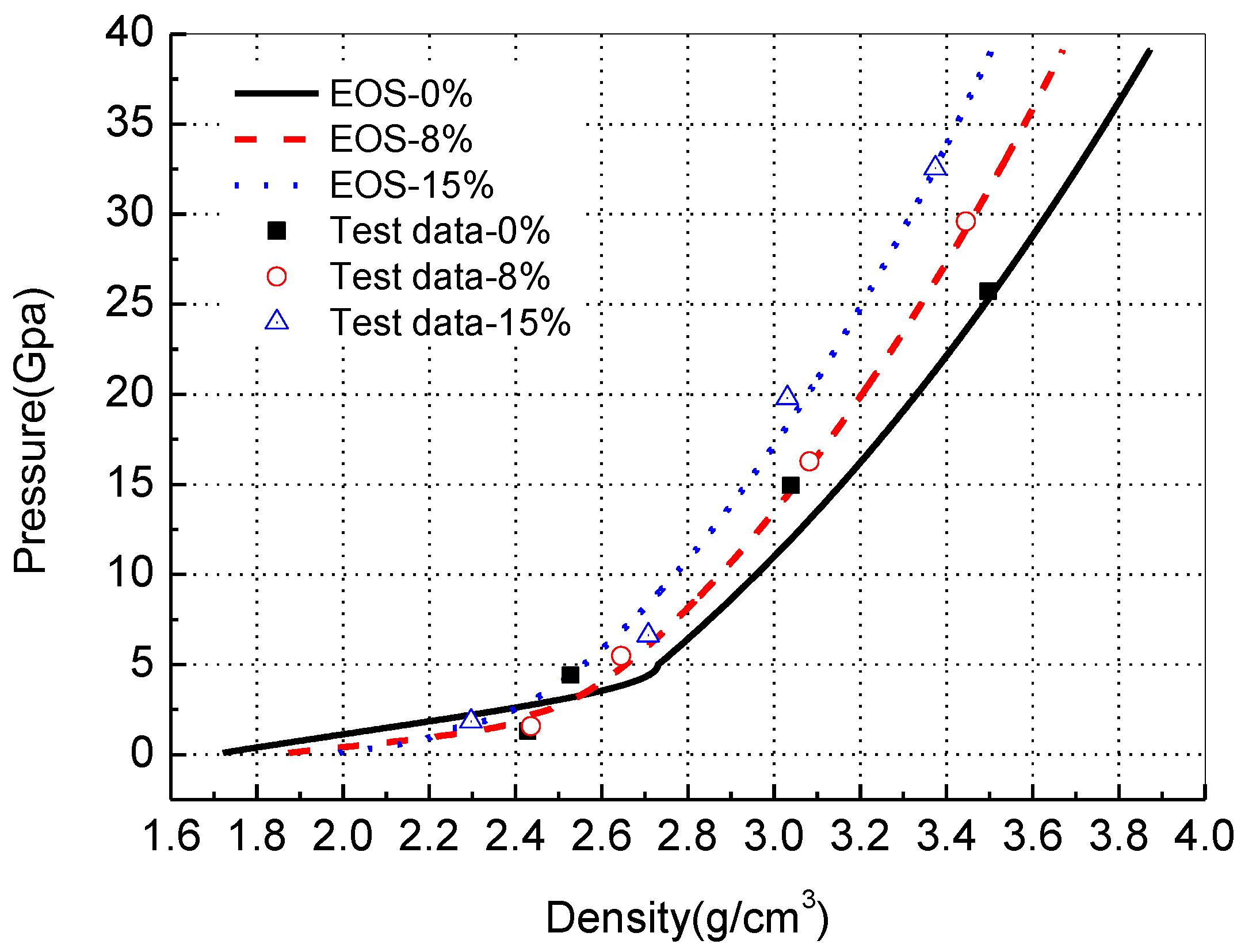
Figure 12 shows the theoretical results from the EOS and the experimental results of the density variation of the clay samples with pressure. It is evident that the compressive strength of the clay sample increased with the increase of the moisture content. The water and the air trapped in the voids of the clay could not be removed under high strain rate and high loading; therefore, the shock compressible behavior of the unsaturated clay was dominated by the compressibility of the trapped water and air and the solid particles. Because water was a relatively incompressible material, the increase of water content led to an increase in the compressive strength of water-bearing clay. Al’tshuler and Pavlovskii [19] carried out shock compressed experiments on unsaturated clay samples with 4% and 20% moisture contents; the mineral components of their clay samples were mainly quartz and kaolin, which were similar to the samples used in this study. They also concluded the same results that the compressive strength of clay increases with the increase of the moisture content.
As indicated by the agreement between the theoretical results and the experimental ones in Figure 12, the EOS of the unsaturated clay proposed in this study could give a better description of the relation between the pressure and the density of the clay, and it could also reflect the different shock compressed behaviors of the unsaturated clay resulting from the moisture content variation.
4. Discussion
- (1)
- For the unsaturated clay, the EOS could be separated into low-pressure range and high-pressure range by the compacted pressure pc. The p-alpha compacted model could be used in the low-pressure range and the solid-water two-constituent mixed EOS could be applied for the high-pressure range.
- (2)
- With the original clay extracted from the southern suburbs of Luoyang city in China, three unsaturated clays with moisture content 0%, 8%, and 15%, respectively, were remolded. The Hugoniot parameters of three unsaturated clays were determined by means of the plate impact experiment on a one-stage and two-stage light gas gun. The results were: when the moisture content is 0%, ρ0 = 1.70 g/cm3, c0 = 1.08 ± 0.30 km/s, s = 1.62 ± 0.17; when the moisture content is 8%, ρ0 = 1.84 g/cm3, c0 = 1.29 ± 0.24 km/s, s = 1.72 ± 0.14; when the moisture content is 15%, ρ0 = 1.96 g/cm3, c0 = 1.91 ± 0.18 km/s, s = 1.71 ± 0.10.
- (3)
- With the Hugoniot parameters and the model of two-stage EOS presented here, the high-pressure EOS up to 30 GPa was developed for the unsaturated clays of three moisture contents and was consistent with the experimental results.
Author Contributions
Conceptualization, X.R.; methodology, X.R. and X.Z.; validation, X.R.; formal analysis, X.Z.; resources, W.T.; data curation, J.Z. and X.R.; writing—original draft preparation, X.R. and X.Z.; writing—review and editing, X.R. and J.Z.; supervision, W.T.; project administration, W.T. All authors have read and agreed to the published version of the manuscript.
Funding
This research received no external funding.
Institutional Review Board Statement
Not applicable.
Informed Consent Statement
Not applicable.
Data Availability Statement
The data can be requested from the corresponding authors.
Acknowledgments
This research was funded by the National Natural Science Foundation of China (Grant No. 11002162 and 11072262). The authors would like to thank Y.Y.Y. Cao for her warm help in revising the English writing. The authors express their sincere thanks to the anonymous reviewers and the editor for their invaluable help in revising this paper.
Conflicts of Interest
The authors declare no conflict of interest.
References
- Henrych, J. The Dynamics of Explosion and Its Use; Elsevier Scientific Publishing Company: New York, NY, USA, 1979; pp. 73–84. [Google Scholar]
- Schofield, A.; Wroth, P. Critical State Soil Mechanics; McGraw-Hill: New York, NY, USA, 1968. [Google Scholar]
- Van Thiel, M.; Shaner, J.; Salinas, E. Compendium of Shock Wave Data. Introduction. Section A1. Elements; California Univ.: Oakland, CA, USA, 1977. [Google Scholar]
- Kalashnikov, N.G.; Pavlovsky, M.N.; Simakov, G.V.; Trunin, R.F. Dynamic compressibility of calcite-group minerals. Izv. Phys. Solid Earth 1973, 2, 23–29. [Google Scholar]
- Trunin, R.F. Rock compressibility in shock waves. Izv. Earth Phys. 1988, 24, 38–42. [Google Scholar]
- Tsembelis, K.; Proud, W.; Vaughan, B. The behavior of sand under shock wave loading: Experiments and simulations. In Proceedings of the 14th DYMAT Technical Meeting on Behavior of Materials at High Strain Rates: Numerical Modeling, Sevilla, Spain, 1 January 2002. [Google Scholar]
- Chapman, D.; Tsembelis, K.; Proud, W. The behaviour of dry sand under shock loading. In Shock Compression of Condensed Matter; American Institute of Physics: Baltimore, MD, USA, 2005. [Google Scholar]
- Reinhart, W.D.; Thornhill, T.F., III; Chhabildas, L.C.; Vogler, T.J.; Brown, J.L. Shock Response of Dry Sand; Sandia National Laboratories: Albuquerque, NM, USA, 2007. [Google Scholar]
- Resnyansky, A.; Bourne, N. Shock Compression of Dry and Hydrated Sand; AIP Conference Proceedings; American Institute of Physics: Baltimore, MD, USA, 2004; pp. 1474–1477. [Google Scholar]
- Wang, Z.; Lu, Y. Numerical analysis on dynamic deformation mechanism of soils under blast loading. Soil Dyn. Earthq. Eng. 2003, 23, 705–714. [Google Scholar] [CrossRef]
- Wang, Z.; Hao, H.; Lu, Y. A three-phase soil model for simulating stress wave propagation due to blast loading. Int. J. Numer. Anal. Methods Geomech. 2004, 28, 33–56. [Google Scholar] [CrossRef]
- Marsh, S.P. LASL Shock Hugoniot Data; University of California Press: Berkeley, CA, USA, 1980; pp. 57–184. [Google Scholar]
- Shi, S.; Chen, P.; Huang, Y. Velocity measurement of magnet induced system for projectile. Chin. J. High Press. Phys. 1991, 5, 205–214. [Google Scholar]
- Zhao, S.W.; Wang, C.L.; Li, X. Experiment research of fiber probe applied in detonation velocity test. J. Appl. Opt. 2015, 36, 327–331. [Google Scholar]
- Schmitt, D.R.; Ahrens, T.J. Shock temperatures in silica glass: Implications for modes of shock-induced deformation, phase transformation, and melting with pressure. J. Geophys. Res. Solid Earth 1989, 94, 5851–5871. [Google Scholar] [CrossRef] [Green Version]
- Herrmann, W. Constitutive equation for the dynamic compaction of ductile porous materials. J. Appl. Phys. 1969, 40, 2490–2499. [Google Scholar] [CrossRef]
- Borg, J.P.; Chapman, D.J.; Tsembelis, K. Dynamic compaction of porous silica powder. J. Appl. Phys. 2005, 98, 073509. [Google Scholar] [CrossRef]
- Borg, J.P.; Cogar, J.R.; Lloyd, A. Computational simulations of the dynamic compaction of porous media. Int. J. Impact Eng. 2006, 33, 109–118. [Google Scholar] [CrossRef]
- Al’tshuler, L.V.; Pavlovskii, M.N. Response of clay and clay shale to heavy dynamic loading. J. Appl. Mech. Tech. Phys. 1971, 12, 161–165. [Google Scholar] [CrossRef]
Figure 1.
Schematic graph of the relation of p and ρ: (a) low pressure part; (b) high pressure part.
Figure 1.
Schematic graph of the relation of p and ρ: (a) low pressure part; (b) high pressure part.

Figure 2.
Schematic of sample mold.

Figure 3.
Schematic of experimental sample preparation.

Figure 4.
The target for plate-impact experiment graph: (a) the sample-holder and the target-stand; (b) back view of the assembled target.
Figure 4.
The target for plate-impact experiment graph: (a) the sample-holder and the target-stand; (b) back view of the assembled target.

Figure 5.
The schematic diagram of the optical probe of quartz fiber.

Figure 6.
The schematic diagram of one single-fiber probe system.

Figure 7.
The schematic diagram for measuring Hugoniot parameters. (a) Arrangement position of fiber-optic pins. (b) Fiber-optic pins test system.
Figure 7.
The schematic diagram for measuring Hugoniot parameters. (a) Arrangement position of fiber-optic pins. (b) Fiber-optic pins test system.

Figure 8.
The typical signals of fiber optical pins in shock experiments: (a) optical pin signals from the first channel; (b) optical pin signals from the second channel.
Figure 8.
The typical signals of fiber optical pins in shock experiments: (a) optical pin signals from the first channel; (b) optical pin signals from the second channel.

Figure 9.
The impedance match method.

Figure 10.
The linear relation Us-up for the clay of three moisture contents.

Figure 11.
Schematic of porous material α(p).

Figure 12.
Comparison of theoretical and experimental data for the equation of state in terms of pressure and density.
Figure 12.
Comparison of theoretical and experimental data for the equation of state in terms of pressure and density.


Table 1.
The mineral components of the dry original clay.
| Components | Quartz | Calcite | Chlorite | Montmorillonite | Illite | Feldspar | Kaolinite | Amphibole | Hematite |
|---|---|---|---|---|---|---|---|---|---|
| Mass (%) | 25 | 7 | 15 | 10 | 15 | 18 | 5 | 3 | 2 |
Table 2.
Physical parameters of clay in plate impact test.
| Sample Number | 1 | 2 | 3 |
|---|---|---|---|
| initial dry density ρd0 (g/cm3) | 1.70 | 1.70 | 1.70 |
| initial wet density ρ0 (g/cm3) | 1.70 | 1.84 | 1.96 |
| sample weight m (g) | 1.03 | 1.11 | 1.18 |
| initial moisture content w (%) | 0 | 8 | 15 |
| initial saturation Sr0 (%) | 0 | 35.8 | 67.4 |
Table 3.
The parameters [11] of flyer materials and Hugoniot.
Table 3.
The parameters [11] of flyer materials and Hugoniot.
| Material | ρ0 (g/cm3) | c0 (km/s) | s |
|---|---|---|---|
| 2024 aluminum alloy | 2.785 | 5.328 | 1.338 |
| copper | 8.93 | 3.94 | 1.489 |
| tantalum | 16.656 | 3.437 | 1.19 |
Table 4.
Experimental results for unsaturated clay.
| Clay Samples | No. | Flyer Materials | Flyer Velocity (km/s) | Shock Wave Arrival Time (ns) | Sample Thickness (mm) | Particle Velocity (km/s) | Shock Wave Velocity (km/s) | Pressure (GPa) |
|---|---|---|---|---|---|---|---|---|
| Dry Clay | 1 | Aluminum | 0.561 | 1868 | 2.98 | 0.48 | 1.60 | 1.29 |
| 2 | Copper | 1.042 | 1054 | 2.96 | 0.92 | 2.81 | 4.40 | |
| 3 | Copper | 2.340 | 658 | 2.94 | 1.97 | 4.47 | 14.95 | |
| 4 | Tantalum | 3.180 | 556 | 3.02 | 2.79 | 5.43 | 25.71 | |
| Wet clay (moisture content: 8%) | 5 | Aluminum | 0.563 | 1564 | 2.94 | 0.46 | 1.88 | 1.58 |
| 6 | Copper | 1.101 | 956 | 2.98 | 0.95 | 3.12 | 5.46 | |
| 7 | Copper | 2.290 | 640 | 3.00 | 1.89 | 4.69 | 16.26 | |
| 8 | Tantalum | 3.190 | 500 | 2.94 | 2.74 | 5.88 | 29.60 | |
| Wet clay (moisture content: 15%) | 9 | Aluminum | 0.495 | 1192 | 3.00 | 0.37 | 2.52 | 1.84 |
| 10 | Copper | 1.142 | 848 | 2.98 | 0.97 | 3.51 | 6.63 | |
| 11 | Copper | 2.370 | 538 | 2.88 | 1.89 | 5.35 | 19.81 | |
| 12 | Tantalum | 3.130 | 478 | 3.01 | 2.64 | 6.30 | 32.54 |
Table 5.
The parameters of equation of state of unsaturated clay.
| EOS | Parameters | Dry Clay | 8% Clay | 15% Clay |
|---|---|---|---|---|
| p-alpha model | Elastic yield strength, pe (GPa) | 0 | 0 | 0 |
| Plastic yield strength, ps (GPa) | 4.97 | 2.15 | 1.38 | |
| Empirical fitting parameter, N | 2 | 2 | 2 | |
| Solid–liquid two-phase model | Fully compacted density, ρc (g/cm3) | 2.73 | 2.42 | 2.23 |
| Water proportion under pc, βwc | 0 | 0.18 | 0.29 | |
| Solid proportion under pc, βsc | 1 | 0.82 | 0.71 | |
| Water phase | ρw0 = 1.0 g/cm3, cw0 = 1500 m/s, kw = 7 | |||
| Solid particle phase | ρs0 = 2.73 g/cm3, cs0 = 4500 m/s, ks = 3 | |||
Publisher’s Note: MDPI stays neutral with regard to jurisdictional claims in published maps and institutional affiliations. |
© 2022 by the authors. Licensee MDPI, Basel, Switzerland. This article is an open access article distributed under the terms and conditions of the Creative Commons Attribution (CC BY) license (https://creativecommons.org/licenses/by/4.0/).
Share and Cite
MDPI and ACS Style
Ran, X.; Zou, X.; Zhou, J.; Tang, W. Shock Properties of One Unsaturated Clay and Its Equation of State Up to 30 GPa. Crystals 2022, 12, 119. https://0-doi-org.brum.beds.ac.uk/10.3390/cryst12010119
AMA Style
Ran X, Zou X, Zhou J, Tang W. Shock Properties of One Unsaturated Clay and Its Equation of State Up to 30 GPa. Crystals. 2022; 12(1):119. https://0-doi-org.brum.beds.ac.uk/10.3390/cryst12010119
Chicago/Turabian StyleRan, Xianwen, Xuan Zou, Jingyuan Zhou, and Wenhui Tang. 2022. "Shock Properties of One Unsaturated Clay and Its Equation of State Up to 30 GPa" Crystals 12, no. 1: 119. https://0-doi-org.brum.beds.ac.uk/10.3390/cryst12010119
Note that from the first issue of 2016, this journal uses article numbers instead of page numbers. See further details here.