
Study on Novel Powder Metallurgy Al-Si Brazing Filler Metal with Flux
by
 ,
,
Wenpan Fei
1, 
Bo Wang
1,2,*,
Yinbin Lou
3,
Weimin Long
1,4,*,
Jianfeng Deng
1,
Lei Zhang
1,4,
Pengzhi Yin
1 and
Shuiqing Wang
3 1
China Innovation Academy of Intelligent Equipment Company, Ltd., Ningbo 315700, China
2
Henan Key Laboratory of Advanced Magnesium Alloy, Zhengzhou Univeristy, Zhengzhou 450002, China
3
Zhejiang Xinrui Brazing Technology Company, Ltd., Shaoxing 312000, China
4
State Key Laboratory of Advanced Brazing Filler Metals and Technology, Zhengzhou Research Institute of Mechanical Engineering Company, Ltd., Zhengzhou 450001, China
*
Authors to whom correspondence should be addressed.
Crystals 2022, 12(4), 544; https://0-doi-org.brum.beds.ac.uk/10.3390/cryst12040544
Submission received: 1 January 2022
/
Revised: 3 April 2022
/
Accepted: 8 April 2022
/
Published: 13 April 2022
(This article belongs to the Special Issue Advances of Welding Materials)
Abstract
:Green brazing is one of the key basic technologies in the manufacturing industry, and the wide application of composite brazing filler metals is a significant method for realizing green and automatic brazing. In the present study, an investigation was conducted into a novel powder metallurgy Al-Si brazing filler metal with flux and the resulting brazed joints of 3003/6061 aluminum alloy. By means of scanning electron microscopy and energy-dispersive analysis, the effect of moisture-resistance performance on the microstructure and the properties of Al-Si brazing filler metal with flux and brazing joint were analyzed. The results reveal that the new type of powder metallurgy Al-12Si brazing filler metal had better moisture-resistance performance than the seamed flux cored brazing filler metal. In an environment with a humidity of 90% and a temperature of 40 °C for 7 days, the moisture absorption rate of the powder metallurgy Al-12Si brazing filler metal with flux was only 0.17%. The wet spreading area of the new powder metallurgy Al-12Si brazing filler metal treated for 3 days in a humid environment was 320 mm2, which was 7% less than that in the dry state. At the same time, the spreading area of the seamed flux cored brazing filler metal under the same conditions was only 80.9% of that in the dry state. The fracture strengths of the 3003 and 6061 aluminum alloy joints brazed by the wetted powder metallurgy Al-12Si brazing filler metal with flux were satisfactory, and scanning electron microscopy examination of the braze-zone revealed that relatively sound joints were obtained. However, obvious pores were observed in the braze-zone of the wetted seamed flux cored brazing filler. The maximum diameter of the pores was increased from 28 μm to 68 μm in the brazing area.
1. Introduction
Aluminum alloys occupy a unique position in modern industrial materials due to the low density, high thermal conductivity, and electrical conductivity thereof [1]. In the manufacturing of artificial satellites, rockets, missiles, microwave components, aircraft or ground radar antennas, automobiles, refrigeration equipment, and other technologies, in order to reduce weight, reduce motorization, efficiency and enhancement, aluminum is used instead of copper, and even instead of steel. As an example, many traditional copper-alloy waveguides and high-frequency devices have been replaced by aluminum alloys. Attempts have been made to replace steel and other metals with aluminum in a variety of fields. The key to whether such metals can be replaced lies in the welding of aluminum and the alloys thereof [2,3,4]. As the first choice for precision welding, brazing is a commonly used aluminum alloy welding method. Compared with fusion welding, in the brazing method, the heating temperature is generally lower than the melting point of the base material, which has no obvious adverse effect on the physical and chemical properties of the base material. The low brazing temperature easily allows for uniform heating of the entire workpiece [5,6].
The brazing filler metals for aluminum alloy brazing are mainly divided into Al-Si based brazing filler metals and Zn-Al-based brazing filler metals. Zn-Al based brazing filler metal has a low melting point and is suitable for brazing with a narrow brazing temperature window or Cu/Al dissimilar metals but must use a large amount of CsAlF4 flux, which is extremely expensive and limited in application [7,8]. Compared with Zn-Al brazing filler metal, Al-Si alloy is mainly brazed with KAlF4 flux, the cost is lower, and only a small amount of CsAlF4 flux is usually needed. As an aluminum-silicon eutectic alloy with a liquidus temperature of 577 °C, the Al-12Si aluminum alloy has good wettability, fluidity, corrosion resistance, and workability of brazing joints. Such alloy is widely used for brazing of pure aluminum, 3XXX series and 6XXX series alloys, including automobile water tanks, air conditioner radiators, microwave devices of aerospace equipment, and others [9].
Traditional Al-Si brazing filler metal is generally used with solid rods or wires in combination with powdered brazing filler metal. However, said brazing filler metal has the problems of uncontrollable brazing filler metal dosage, easy moisture absorption, brazing filler metal failure, and pollution of the environment. At the same time, there are difficulties in ensuring stable welding quality with manual brazing filler metal, and ablation or even melting of the base material can easily occur. The current situation is incompatible with the recognized goals of the global manufacturing industry to reduce resource and energy consumption and build a green manufacturing system. The automation requirements established by the transformation and upgrading of the manufacturing industry can also not be met. As such, self-fluxing composite brazing filler metals with high efficiency and energy-saving properties have progressively emerged as a new focus of research and development. In the preparation stage of composite brazing filler metals, the filler metal and the flux are combined into one according to a specific ratio, so as to achieve the functions of quantitative and automatic addition of the filler metal and flux [10]. Common composite brazing filler metals include flux-cored brazing filler metals, flux coated brazing filler metals, and powder metallurgy type brazing filler metals [11]. Based on the airtightness of the brazing filler metal, flux-cored brazing filler metals are divided into seam type and seamless type. The seamed flux-cored brazing filler metals have the hidden dangers of moisture absorption and powder leakage, while the seamless flux cored brazing filler metals are prone to splashing and the preparation cost thereof is relatively high. Because the flux is exposed, the moisture resistance and fixation of the flux become hindrances that affect the wide application of the flux-coated brazing filler metals. Powder metallurgy composite brazing filler metals not only have the advantages of self-fluxing filler metal positioning, fixed temperature, and quantitative and accurate response, but also have the advantages of seamless flux-cored brazing filler metal such as anti-moisture absorption, no powder leakage, low cost, and are the preform preparation of flux-coated brazing filler metal. Thus, high-quality powder metallurgy composite brazing filler metals have become a significant research topic in recent years [12].
At present, there are cases of mature application of Al-Si composite brazing filler metals in the international market, such as the welding ring and welding rod produced by SunKwang Brazing Filler Metal Co., Ltd. in South Korea [13] and the new brazing material TRILLIUM™ developed by Gränges AB Sweden [14,15,16]. As opposed to a traditional brazing flux-on-braze approach, flux KAlF4 is embedded into the braze clad/filler alloy. However, the process characteristics of the above two composite brazing filler metals are powder forging and spray forming, respectively, which have the disadvantages of high mold machining accuracy, high cost, and low production efficiency. Li Xiu Peng of Zhengzhou Machinery Research Institute and several others prepared a self-flux aluminum welding ring by hot pressing sintering [17,18], which could meet the user needs of common aluminum alloys. Despite such progress, the self-fluxing aluminum welding ring still suffers from excessive oxidation during the fabrication process. Therefore, it is of considerable significance to develop a new type of powder composite brazing filler metal with low preparation difficulty, low cost, and high purity to meet the brazing requirements of aluminum alloy products.
2. Experimental Methods and Equipment
A self-made continuous extrusion die was used to realize the continuous preparation of a powder metallurgy brazing filler metal under gas protection. The specifications of the self-made novel powder metallurgy Al-12Si brazing filler metal with flux (hereinafter referred to as PM brazing filler metal) can be a welding ring and a welding rod. In the present study, a φ2.3 mm welding rod was selected for performance characterization and organization analysis. In addition to the self-made PM brazing filler metal, the well-known SKA 200 type composite brazing filler metal (hereinafter referred to as SKA brazing filler metal) made in South Korea and domestic seamed flux-cored Al-12Si brazing filler metal (hereinafter referred to as SFC brazing filler metal) were selected for simultaneous moisture-resistance and brazing testing, so as to compare the moisture resistance and brazing performance of various brazing filler metals. The hot and humid environment was simulated by the model DEJA–100 programmable constant temperature and humidity machine. The humidity in the simulation test was 90%, and the temperature was 40 °C. According to the duration of moisture, three groups of 0 days, 3 days, and 7 days were established. The details are shown in Table 1. The moisture resistance of the brazing filler metals was determined by calculating the moisture absorption rate of the fluxes in different time periods. The moisture absorption rate of fluxes refers to the ability of the flux to absorb water within a period of time in the composite brazing filler metal. The calculation formula is:
where W1, W0, and w represent the weight of wet flux, weight of dry flux and the moisture absorption rate.
In the wetting and spreading performance tests, 3003 aluminum alloy was processed into plates with the dimensions of 40 × 40 × 2 mm3, and the brazing filler metal was placed in the center of the test plate for the wetting and spreading test. The area occupied by the brazing filler metal on the test plate after heating and melting was taken as the spreading area, as shown in Figure 1a. The spreading experiment was repeated 5 times, and the average of the 5 experiments was calculated. The 3003 and 6061 aluminum alloys were processed into standard samples for shear testing. The shear strength sample size is shown in Figure 1b. The spreading test was conducted according to China’s National Standard GB/T 11364–2008 [19], and the stretching rate was 1 mm/min. The spreading performance was evaluated by the spreading area of the brazing filler metals on 3003 aluminum alloy. Different types of brazing filler metals of 100 mg were placed on 3003 plates, heated at 620 °C for 1 min in an electrical resistance furnace, and then the spreading areas were measured using Image-Pro Plus software.
The base material was cleaned with a special cleaning agent (which could effectively remove oil stains) before brazing and then cleaned in an ultrasonic cleaner with absolute ethanol for 15 min before drying naturally. The lap length of the brazed joint was 2 mm or 5 mm, the lap gap was 0.2 mm, and the XR–800 flame brazing device was used for brazing. The strengths of the brazed joints were tested on an electronic universal testing machine according to China’s National Standard GB/T 11363-2008 [20]. To ensure the accuracy and reliability of the results, all tests were performed five times under the same conditions.
The solidus and liquidus temperatures of the brazing alloys were determined using a differential scanning calorimeter (DSC, Netzsch STA 449F) under a nitrogen atmosphere with heating at a rate of 10 °C/min. The microstructure of the brazing filler metal and joints interfaces were characterized by employing an ultra-depth-of-field microscope and scanning electron microscopy (SEM, ZEISS EVO 10) with an energy dispersive spectrometer (EDS).
3. Results and Discussion
3.1. Moisture Resistance of Composite Brazing Filler Metal
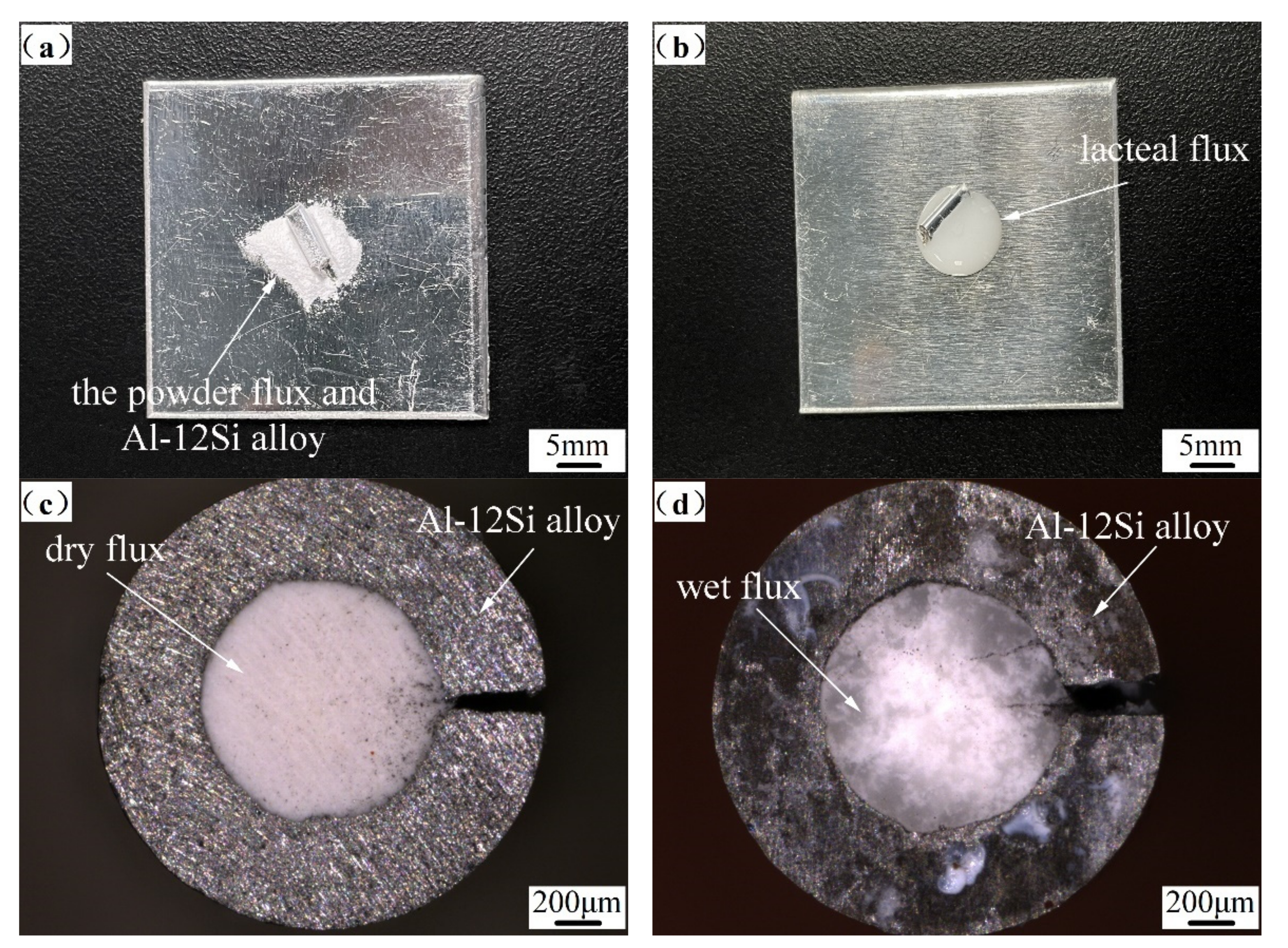
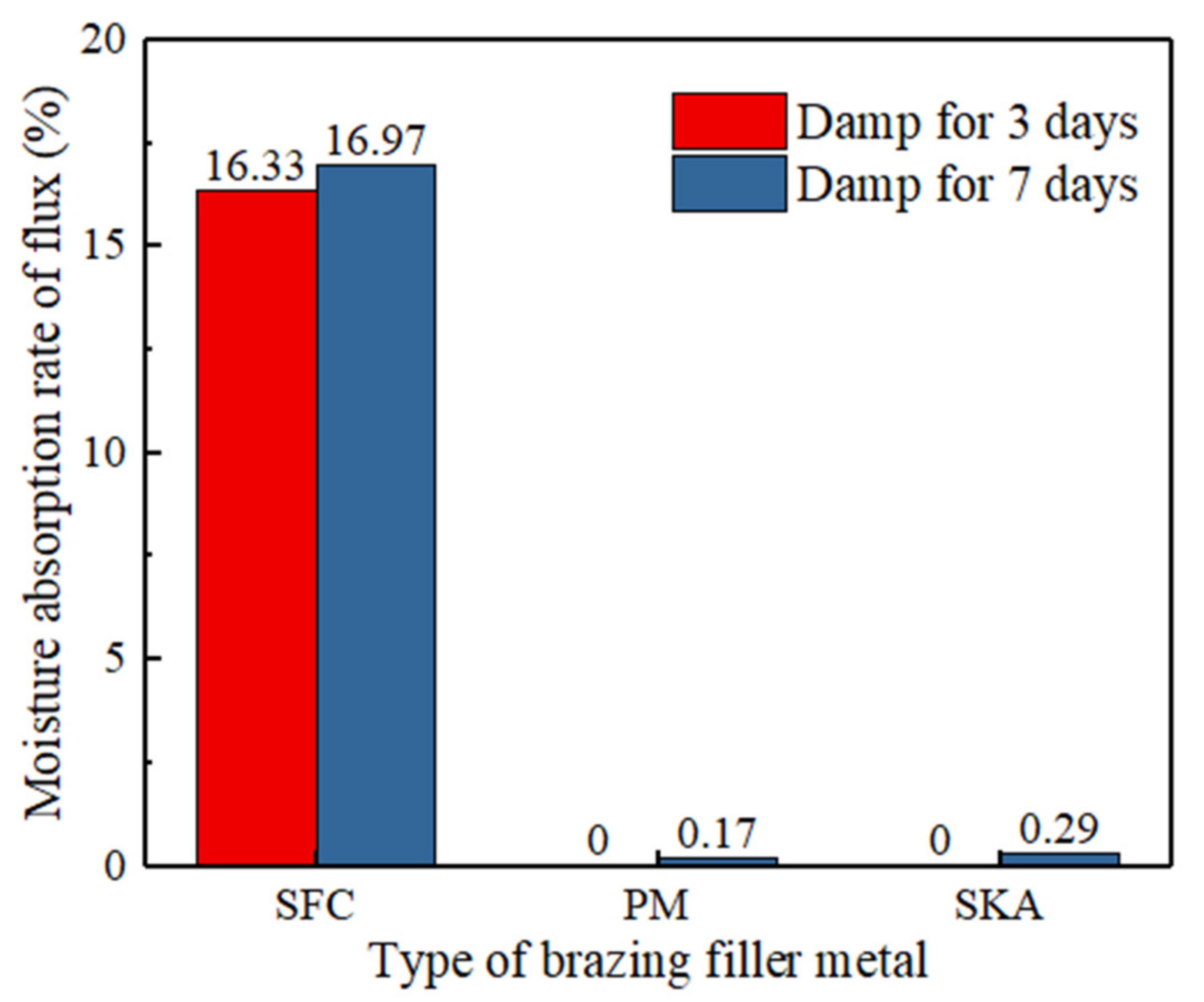
In the present study, to conduct moisture absorption tests for different lengths of time, SFC brazing filler metal, PM brazing filler metal, SKA brazing filler metal, the powder flux, and Al-12Si alloy were placed in an environment with a humidity of 90% and a temperature of 40 °C at the same time. According to Formula (1), the moisture absorption rates of different brazing filler metals were calculated, and the exposed powder flux reached 84.5% of moisture absorption rate in 0.5 days, and the moisture absorption rate of the flux was as high as 103% within 1 day. The flux before and after moisture absorption is shown in Figure 2a,b, which show a change from discrete powder to emulsions. The other three kinds of brazing filler metal could reflect the different moisture absorption performances according to the quality changes. The results are shown in Figure 3. The anti-moisture absorption capacity of the SFC brazing filler metal was significantly weaker than that of the composite brazing filler metal. The moisture absorption rate of the SFC brazing filler metal after 7 days in a humid environment reached 16.97%. The moisture absorption rate of the composite brazing filler metal was significantly lower than that of the SFC brazing filler metal. For instance, after 7 days, the moisture absorption test revealed that the moisture absorption rates of the PM brazing filler metal and the SKA brazing filler metal were only 0.17% and 0.29%, respectively. An observation can be made from Figure 2c,d that after 7 days of moisture absorption, the flux in the SFC brazing filler metal was obviously damp, the flux changed from white to translucent, and part of the milky flux flowed to the coating metal. The filler metal became oxidized and blackened under the joint action of the flux and water, the impurities on the surface of the brazing filler metal alloy returned to the flux, and the flux became contaminated.
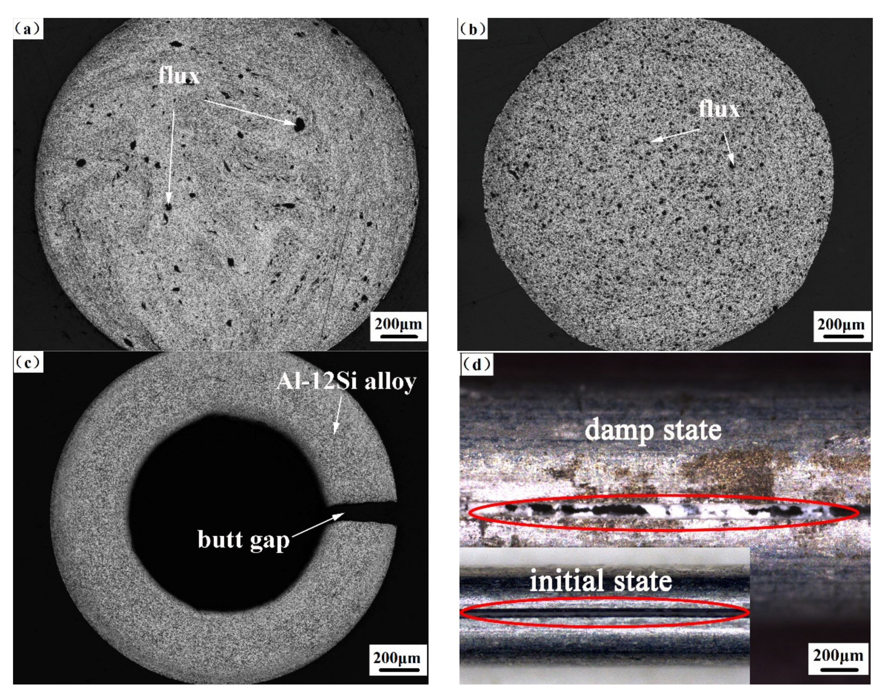
The three kinds of brazing filler metals were placed in a humid environment with a humidity of 90% and a temperature of 40 °C for 7 days. The moisture absorption rate of the SFC brazing filler metal was 74 times and 58 times that of the PM brazing filler metal and the SKA brazing filler metal, respectively. Further, the rate was much higher than the powder flux, indicating that the moisture resistance of the PM brazing filler metal was obviously better than the powder flux and the SFC brazing filler metal. By observing the cross-sectional metallographic diagrams of the three brazing filler metals, findings were made that the brazing flux of the composite brazing filler metal was completely covered with the Al-12Si alloy. As shown by the black area in Figure 4a,b, the black flux mass was surrounded by the white Al-12Si alloy, except for a small amount of brazing flux exposed in the cross-section, which could effectively isolate the brazing flux from contact with humid air. Figure 4c shows the cross-sectional morphology of the SFC brazing filler metal. The flux at the cross-section of the SFC brazing filler metal had a large area exposed to the air, and the butt gap of the coating was also the main reason that the flux was damp. As shown in Figure 4d, the flux in the butt gap in the SFC brazing filler metal had a turbulent flow. When the flux at the SFC brazing filler metal was not damp, a neat and compact initial state was exhibited. After beaming damp, the flux flows to the gap and collapses. As such, the particularity of the preparation process of the composite brazing filler metal could significantly improve the moisture resistance of the brazing filler metal.
3.2. Brazing Filler Metal Characteristics and Spreading Performance
3.2.1. Characteristics Analysis
DSC analysis was performed on the composite brazing filler metals. Figure 5 shows the DSC curves of filler alloy, flux, and composite brazing filler metal. Figure 5a,b are the melting characteristics of the Al-12Si wire alloy and the flux, respectively. An observation can be made that the melting point of the Al-Si eutectic alloy was about 574.44 °C, and the starting working temperature of flux was 547.98 °C. According to the principle of temperature matching between flux and alloy [1], the flux was completely suitable for the Al-Si composite brazing filler metal. Figure 5c,d show the DSC–TG curves of the SKA brazing filler metal and the PM brazing filler metal. An observation can be made that the melting temperatures of the two brazing filler metals were considerably close, and the melting starting temperatures were 567.3 °C and 570.9 °C, respectively, indicating that the two brazing filler metals were suitable for the same brazing process.
3.2.2. Spreading Performance
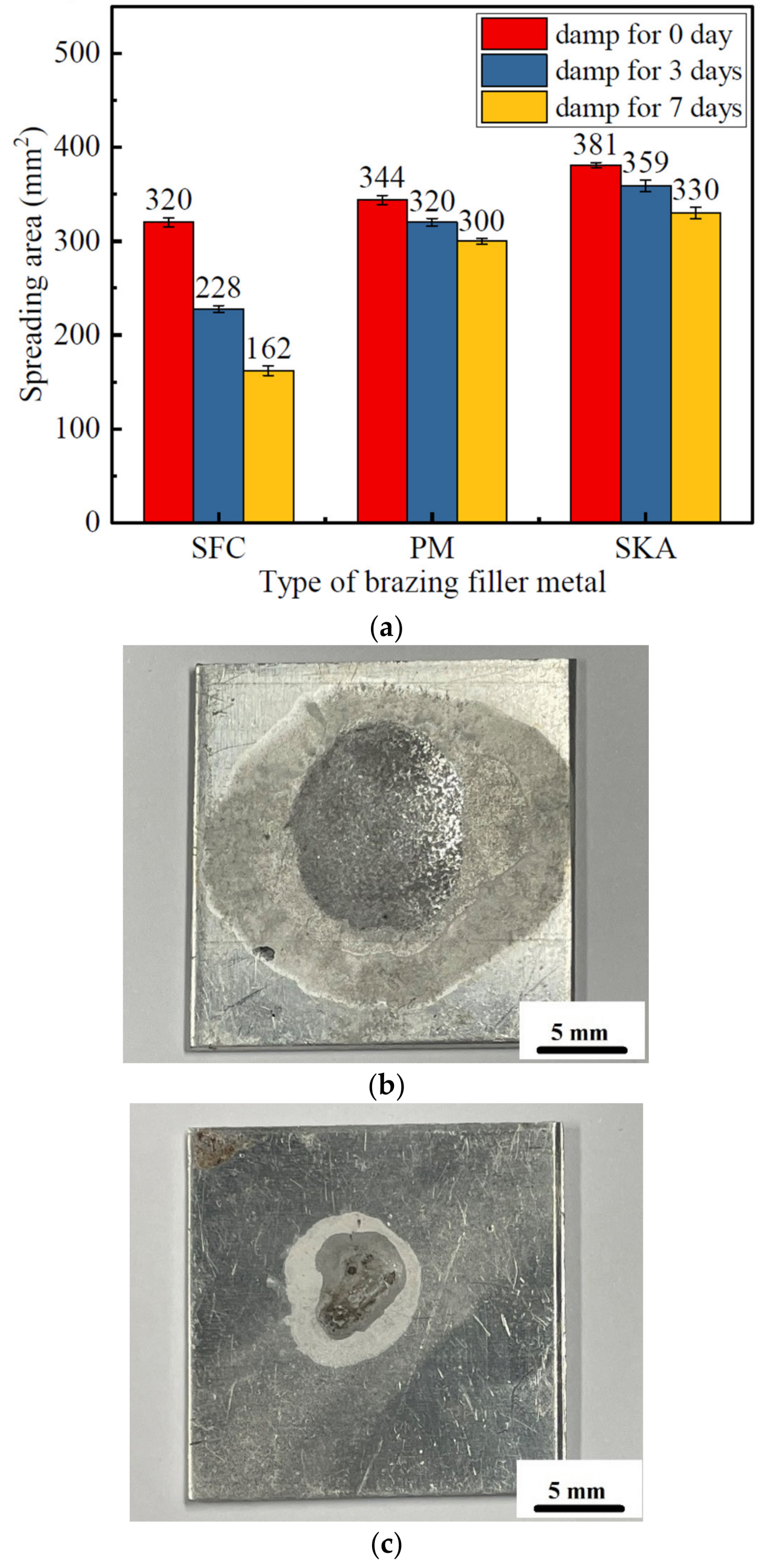
In the present study, different brazing filler metals of the same quality in the dry state were weighed for spreading tests. As shown in Figure 6a, according to the changes in the spreading area, the spreading properties of the three types of brazing filler metals were found to all be affected by the humid environment. The spreading area of the brazing filler metal gradually decreased as more time was spent stored in the humid environment. The traditional powder flux was considerably susceptible to moisture, and the spreading performance was significantly reduced. Figure 6b,c show comparison diagrams of the spread test of the non-damp powdered flux and damp powdered flux, in which the dry powder changed from granular to paste after becoming damp. After heating and melting, the spreading area of the Al-12Si alloy was sharply reduced. At the same time, there were numerous dark brown oxidized impurities on the surface of the molten filler metal, indicating that the powdered flux became inactive after becoming severely damp, as shown in Figure 6c. An observation can be made from Figure 6b that the spreading area of SFC brazing filler metals was only 228 mm2, which was significantly smaller than that in a dry environment and also smaller than that of the composite brazing filler metals. In a dry environment, the spreading area of the PM brazing filler metals was lower than that of the SKA brazing filler metal. Such findings could be attributed to the oxygen content of the Al-12Si powder used in the PM brazing filler metal being higher than that of the SKA, in addition to the activity of the flux being reduced due to the influence of high temperature. As a result, the spreading area of the PM brazing filler metal was slightly smaller than that of the SKA brazing filler metal. In the subsequent anti-moisture absorption experiment, the spread area of the two composite brazing filler metals had a tendency to decrease, but the change was small. The spreading areas of PM and SKA brazing filler metals exposed to moisture for 3 days were 320 mm2 and 359 mm2, respectively, which were only 7% and 5.8% less than in the dry state. However, the spreading area of the SFC brazing filler metal was significantly reduced, being only 80.9% of that under dry conditions, indicating that the PM brazing filler metal and the SKA brazing filler metal had good moisture-resistance properties.
3.3. Brazing Filler Metal Microstructure Analysis
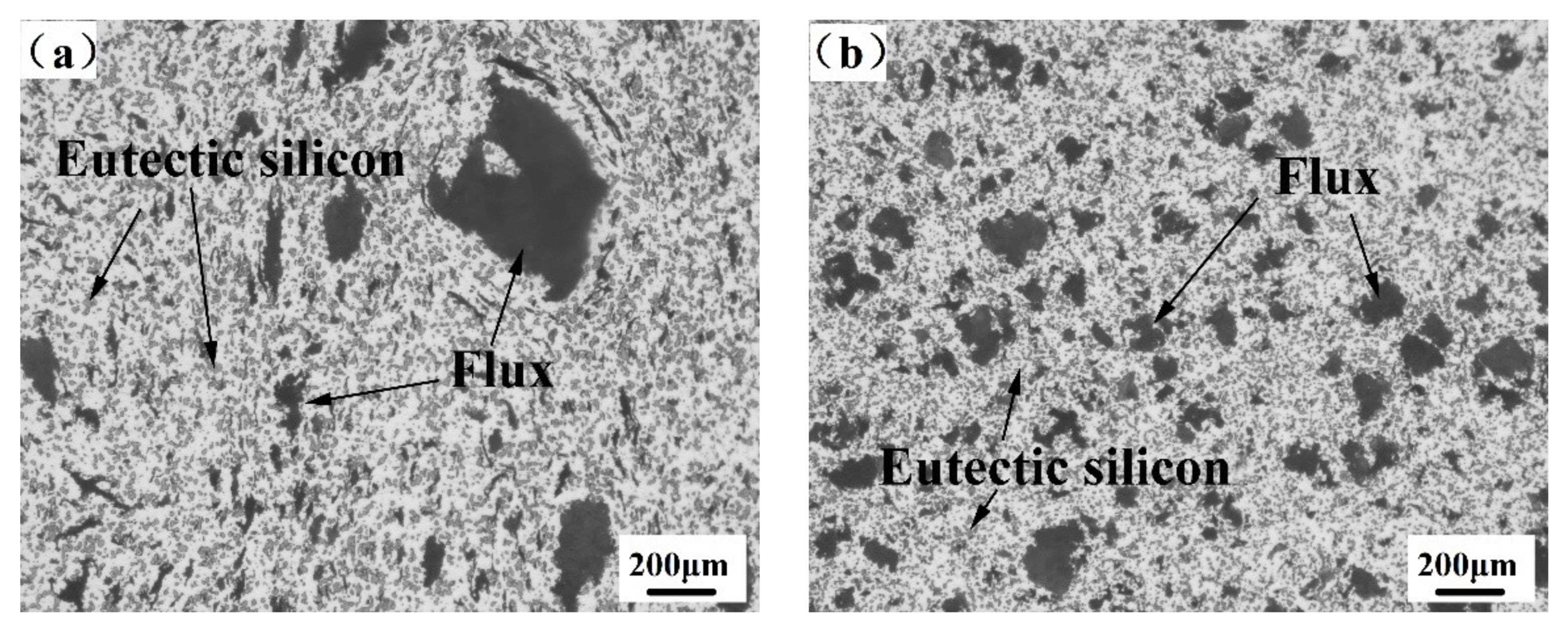
Through a metallurgical microscope, the cross-sectional structure and flux distribution of the composite brazing filler metal could be observed, as shown in Figure 7. There was no primary silicon in the SKA brazing filler metal and the PM brazing filler metal, and the size of the eutectic silicon was small and uniform. Although the fluxes of the two composite brazing filler metals were embedded in the Al-12Si alloy, the morphology and distribution of the flux were obviously different. The size of the flux agglomeration of the PM brazing filler metal was different. The diameter of the largest flux cluster was about 80.56 μm, and the smallest diameter was about 4.04 μm. The shape was irregular and geometric, with sharp edges and corners, as shown in Figure 7a. The flux clusters in the SKA brazing filler metal were mostly ellipsoidal, and the distribution was relatively uniform. The diameter of the largest flux cluster was about 28.27 μm, and the smallest diameter was about 8.77 μm, as shown in Figure 7b. After calculation, the average diameters of the flux in the PM brazing filler metal and the SKA were 31.46 μm and 17.73 μm, respectively, indicating that the flux of the PM brazing filler metal could more easily agglomerate under the condition of the same content. Preliminary analysis shows that the difference in the preparation process of the composite brazing filler metal resulted in a large size difference in the agglomerated flux in the PM brazing filler metal. Such findings could be attributed to the particle size of the flux before mixing not being uniform, the mixing time being too short, or the different structure design of the extrusion die making the extrusion material mix and flow in the mold different. The aforementioned factors would indirectly lead to changes in the distribution of flux and filler metal, but the mechanisms need to be further investigated.
3.4. Microstructure and Properties of Brazed Joints
3.4.1. Defects of Brazed Joints
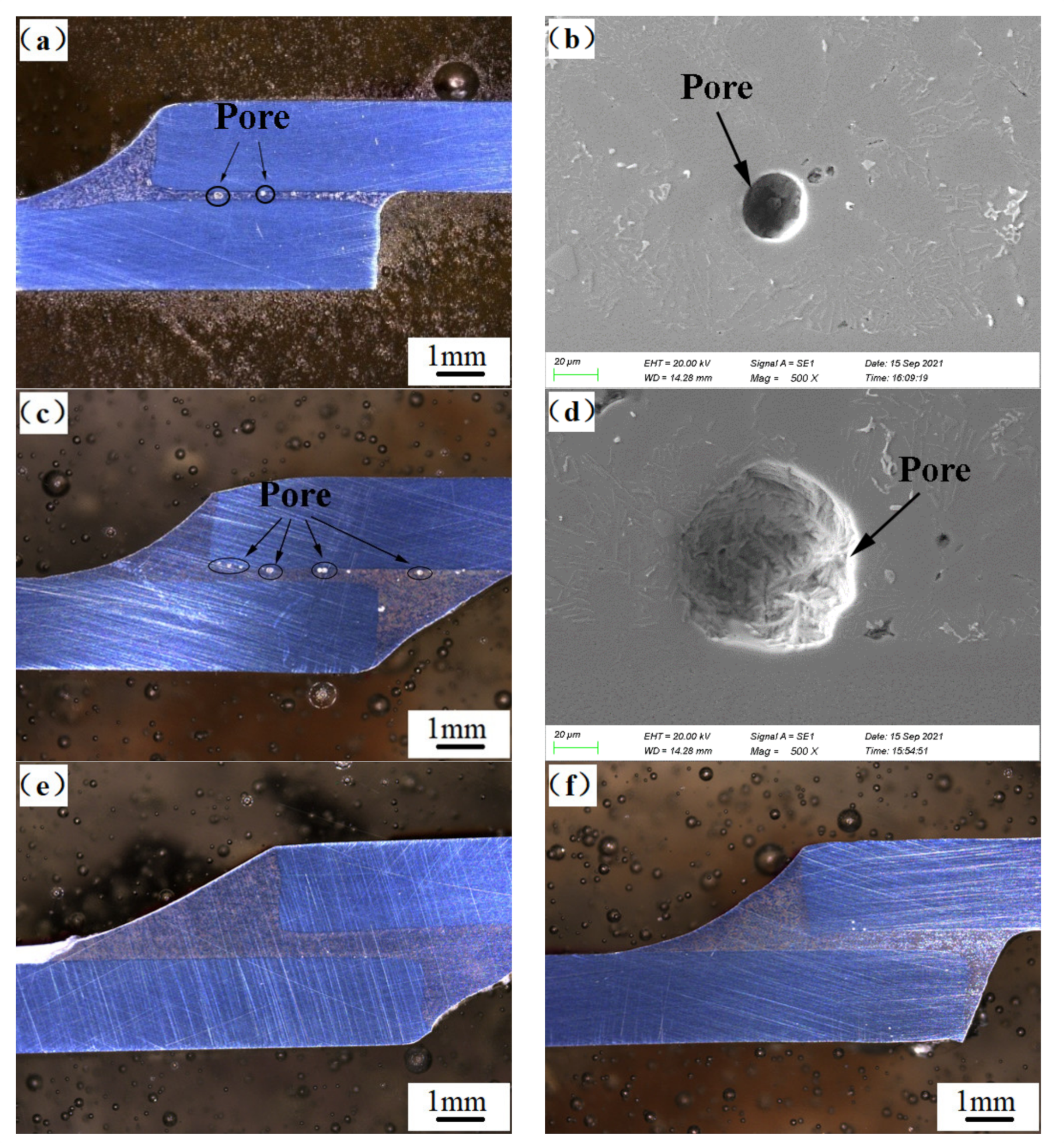
Figure 8 shows the macro morphology and pore defects of the three types of brazed joints under the ultra-depth-of-field microscope. There were no obvious pores or inclusions in the damp brazing filler metal brazed joints. Obvious pores could be found on the SFC brazing filler metal brazed joints, as shown in Figure 8a,c. With the extension of the damp time, the number of pores increased, and the size was increased. As shown in Figure 8b,d, the maximum pore diameter increased from 23 μm to 68 μm. After 7 days of damp testing, the composite brazing filler metal brazed joints still had no obvious pores, as shown in Figure 8e,f. The pores of the SFC brazing filler metal joints could be mainly ascribed to two factors. Firstly, after the brazing filler metal became damp, as the filler metal melted and the water in the flux evaporated, the aluminum reacted with the water vapor to generate hydrogen, and the solubility of hydrogen varied with the rapid cooling of the aluminum alloy brazing material decreasing sharply. Additionally, part of the hydrogen did not have time to overflow the molten brazing material to produce pores. Secondly, the Al2O3 film produced on the surface of the filler metal alloy had a loose and porous structure, which could easily adsorb water vapor and hydrogen during heating. Particularly in the range of 600–700 °C, the adsorption capacity of Al2O3 film was the strongest [21,22]. When the flux was damp, the activity thereof was reduced, and the oxide film could not be completely removed, causing a part of the water vapor and hydrogen in the Al2O3 film to enter the brazing joint, thereby generating pores. In summary, the composite brazing filler metal could significantly reduce the generation of pores in the brazed joint due to moisture, being beneficial for improving the density and mechanical properties of the brazed joint.
3.4.2. Microstructure of Brazed Joint
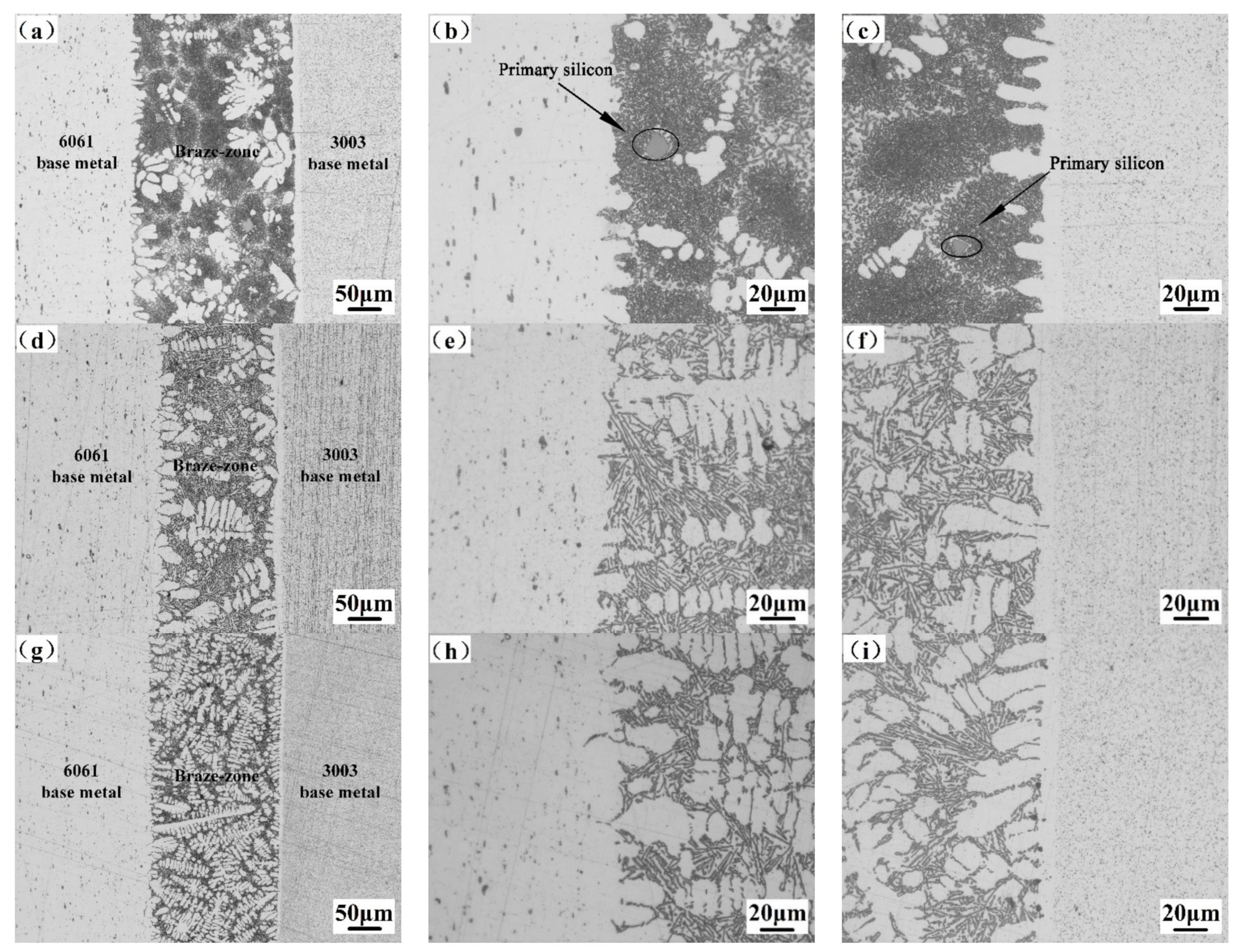
In order to confirm whether the wet flux had an effect on the structure of the brazed joint, an optical microscope was used for observation. After comparison, the wet flux was found to have no obvious influence on the microstructure of the brazing joint. Figure 9 shows the microstructure of dissimilar joints by flame brazing of the 3003 and 6061 aluminum alloys. Figure 9a,d,g are the low magnification microstructures of SFC, PM, and SKA brazing joints, respectively. By comparing the morphology of the brazed joint under the low power lens, a small amount of the primary silicon was found in the welding seam of the SFC brazing filler metal, as shown in Figure 9b,c. However, no obvious bulk primary silicon was found in the PM and the SKA, as shown in Figure 9e,f,h,i. The reason may be that the preparation process of the brazing filler metal was different. The composite brazing filler metal made of micron-level fine powder after extrusion had finer grains. The primary silicon in the SFA brazing filler metal was not broken enough and still contained a small amount of larger primary silicon. After the secondary remelting of the brazing process, the weld would generate a larger bulk of primary silicon as the mass points of the coarse grains in the filler metal. Because of the existence of primary silicon, cracks easily formed and expanded at the corners of the primary silicon, which could eventually lead to a decrease in the mechanical properties of the brazed joint [23,24].
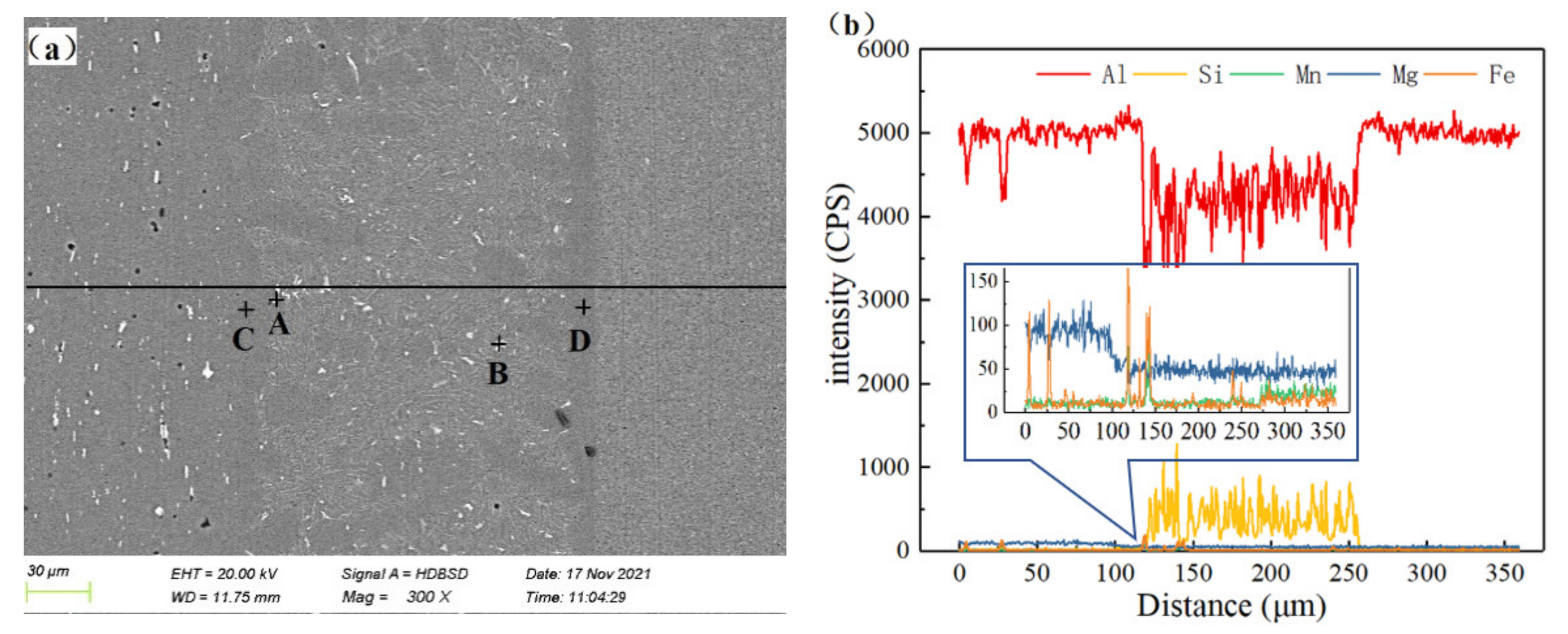
The line scan function of EDS was used to analyze the elemental distribution of the cross-section of the brazed joint. The results reveal that the distribution of Al and Si elements was consistent with that of the brazed joint. The Mg in the 6061 base material and the Mn in the 3003 base material were significantly reduced at the interface between the base material and the weld, as shown in Figure 10. There was an obvious interface layer on the 3003 aluminum alloy side. The interface layer was mainly composed of Al and contained a small amount of Si. Figure 10a shows that the 3003 base material and the brazing joint formed an α-Al interface layer with uniform thickness. Mn was mainly concentrated in the 3003 base material area, and 6061 base material also contained 0.02% Mn. Through scanning points in the brazing seam, as shown in points A and B, the brazing filler metal was found to contain Mn. As such, an assumption could be made that the Mn in the base material diffused into the brazed joint from both ends. According to the elemental composition of point C, a small amount of Mg was found to have diffused in the weld on the side of the 6061 base material. Al, Mg, and Si elements were present in the interface layer on the 6061 side.
Figure 11 shows the high magnification SEM microstructures, and the elemental mappings of the PM brazed joint. The results reveal that the Si only accumulated at the eutectic silicon in the brazing seam area and had no tendency to diffuse to the base material. The Mg in the 6061 base material diffused to the braze metal obviously, while the Mn in the 3003 base material formed a relatively regular boundary line at the interface of the braze-3003 base material, indicating that the Mn in the 3003 base material had basically no diffusion reaction. The observed results are consistent with the data in Table 2. At the same time, the white needle-like phase in the brazing seam area was found to contain a higher amount of Fe elements. According to previous research [25,26], the white needle-like phases around the eutectic silicon are most likely AlxFeySiz intermetallic compounds, which will reduce the strength and plasticity of the brazed joint.
3.4.3. Mechanical Properties of the Brazed Joints
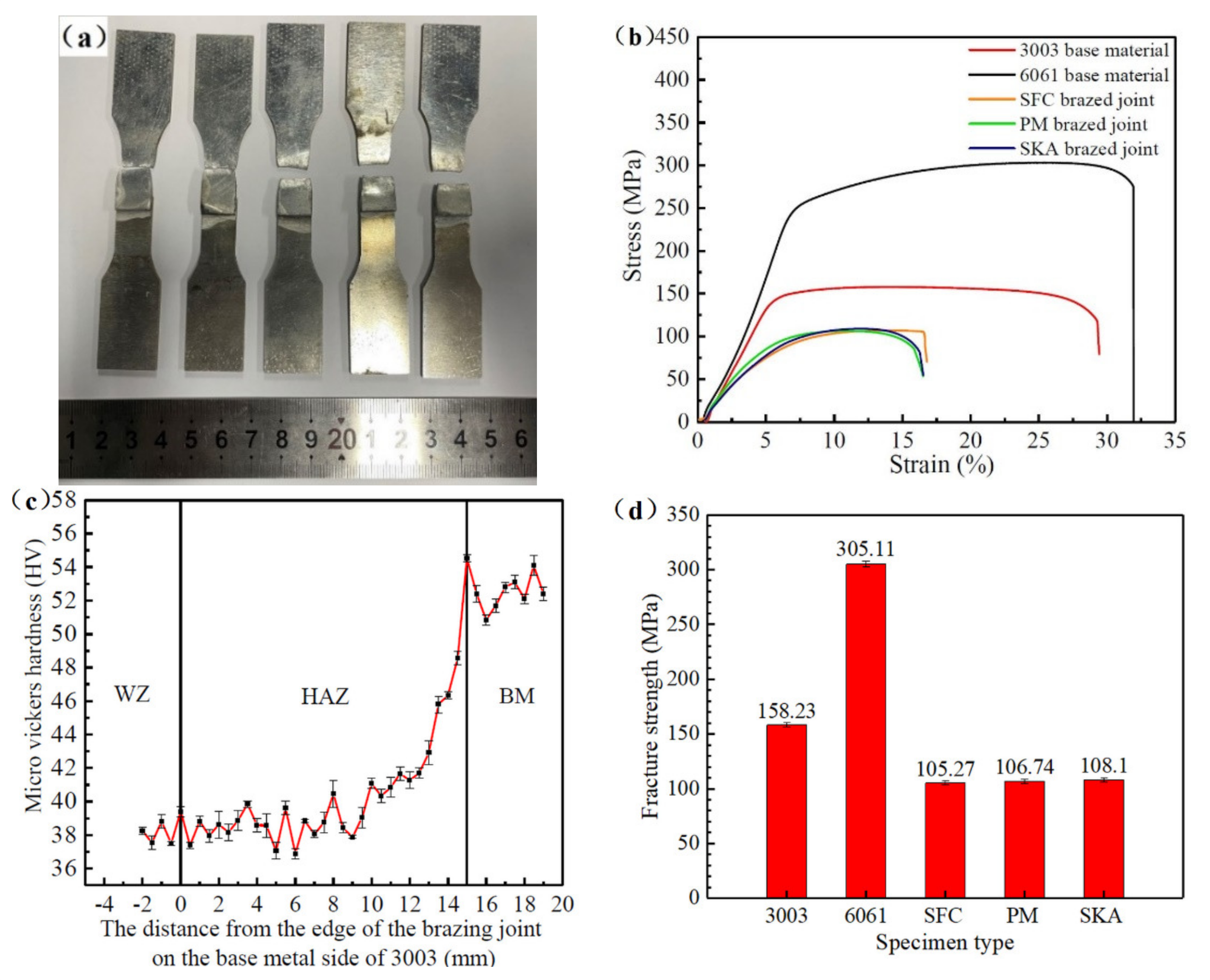
Shear strength tests on the brazing joints of three kinds of brazing filler metals were conducted. When the brazing filler metals were subjected to damp treatment, the standard shear specimens of the brazing joints all fractured in the heat-affected zone (HAZ) of the 3003 base material (BM). As shown in Figure 12b,d, The fracture strength fluctuated between 103–109 MPa, and the average value of the PM brazed joints was 106.74 MPa. The standard samples were welded with damp brazing filler metals. By observing the stress-strain curve, the tensile strength of the base material 6061 was 305.11 MPa, and the tensile strength of the 3003 base material was 158.27 MPa. After brazing, the fracturing occurred in the heat-affected zone of the 3003 base material, and the fracture strength was 105.23 MPa. Based on previous research [27,28], the recrystallization temperature of the 3003 base material is different due to different homogenization treatments. Usually, the temperature range is between 400 °C and 500 °C. The brazing temperature in the present study was 620 °C. Thus, an assumption could be made that the 3003 base material had recrystallization growth, and the strength was reduced. As shown in Figure 12c, the microhardness of the 3003 base metal (BM) decreased significantly in the range of 12–14 mm from the joint edge, and the lowest hardness point appeared at 6 mm from the brazed joint, which was consistent with the fracture location of a tensile specimen. It was proved that the mechanical properties of the 3003 base metal were degraded by the influence of welding heat input.
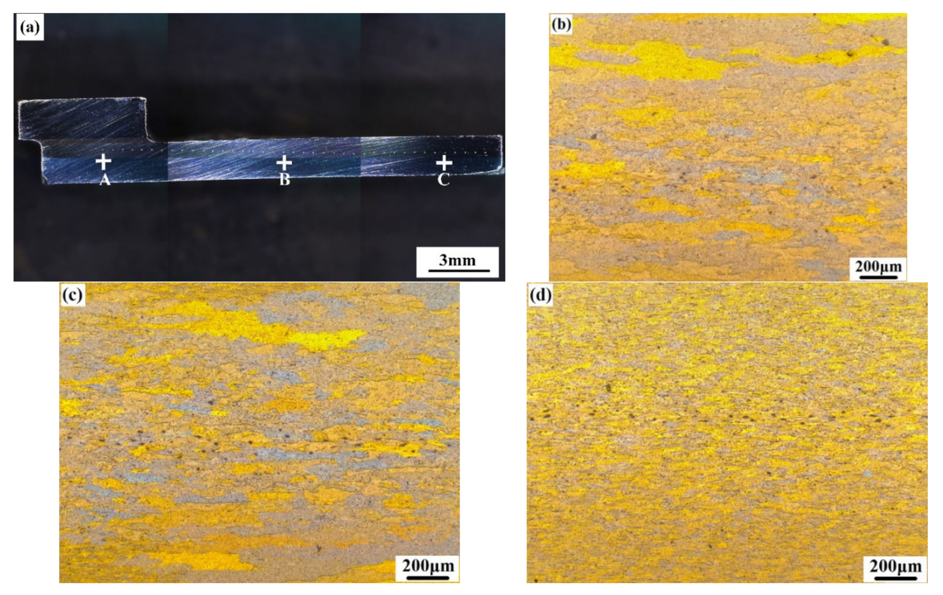
By observing the grain size of the microstructure of the brazed joint, it was found that the grain of the 3003 base metal changed significantly under the influence of welding heat input. Points A, B, and C represented the weld zone (WZ), heat-affected zone, and base-metal zone of the brazed joint in Figure 13a, respectively. Among them, the B point of the heat-affected zone was the lowest point of microhardness. Since the 3003 aluminum alloy sheet was rolled, the grains of the base metal in the initial state were slender fibrous grains extending along the rolling direction of the sheet, as shown in d. By comparing the grain sizes at points A and B, it was found that the grain growth in the heat-affected zone was obvious, and the grain size at the edge was larger than that in the core. The grain size in the weld zone was increased, and the fine fibrous grains in the original state have grown up after recrystallization, and the longest grain size can reach several millimeters, such as Figure 13b,c. In the tensile test, the fracture occurred in the heat-affected zone, and the hardness point of the brazed joint was also located in the heat-affected zone, as shown in Figure 12c. According to experiments, the lowest point of hardness in the heat-affected zone was the tensile fracture point. It can be seen from the figure that the grain size at the lowest hardness point was increased, and the grain size uniformity was poor. According to the research, more grain boundaries can better play the role of grain boundary strengthening, and smaller grain sizes can improve the plasticity of metals. The coarse grains in the heat-affected zone and the weld zone led to a decrease in the length of the grain boundary. So the mechanical properties of the heat-affected zone and the brazed seam zone of the brazed joint were obviously weaker than those of the base metal zone without grain growth. Therefore, the weak point of the brazed joint is the heat-affected zone, and the lap joint interface strength of the brazed seam is higher, which can meet the needs of brazing.
In the present study, the lap width of the base material was adjusted, and the lap area was reduced to make the brazing seam break during the experiment so as to achieve the purpose of testing the shear strength of the brazing seam. Table 3 shows the mechanical properties of the brazed joints with different lap widths. An observation can be made that reducing the lap width to 40% of the original did not cause the brazing seam to break. However, according to the existing data, the brazing seam withstood a shear strength of at least 83 MPa under a lap width of 2 mm and still did not fail. Such findings indicate that the shear strength of the brazing seam was ≥83 Mpa.
4. Conclusions
- (1)
- The moisture-resistance performance of composite brazing filler metal was obviously better than unprotected powder flux and SFC brazing filler metal with insufficient protection effect. After different brazing filler metals were placed in a humid environment for 7 days, the moisture absorption rate of the SFC was 16.97%, which was 74 times and 58 times that of the PM brazing filler metal and the SKA brazing filler metal, respectively.
- (2)
- The spreading areas of the SKA brazing filler metal and the PM brazing filler metal in a humid environment for 3 days were 359 mm2 and 320 mm2, respectively, which were only 5.8% and 7% less than those in the dry state. The spread area of the SFC brazing filler metal was significantly reduced, being 80.9% under dry conditions.
- (3)
- As the flux was affected by moisture, with the increase in moisture absorption, the pores of the SFC brazing joints increased, and the size was increased. The maximum pore diameter increased from 23 μm to 68 μm, while the composite brazing joints still had no obvious pores.
- (4)
- The microstructure and element distribution of the brazing joints of the three kinds of brazing filler metals were not affected by the moisture absorption of the flux. The microhardness of the 3003 base material decreased significantly in the heat-affected zone, and fracturing occurred. The results reveal that the shear strength of the brazed joint was ≥83 Mpa.
Author Contributions
Conceptualization, W.L. and B.W.; methodology, B.W. and W.F.; software, J.D. and P.Y.; validation, W.F.; formal analysis, Y.L.; investigation, W.F.; resources, W.F.; data curation, W.F.; writing—original draft preparation, W.F.; writing—review and editing, W.F.; visualization, W.F.; supervision, L.Z. and S.W.; project administration, B.W.; funding acquisition, W.L. and S.W. All authors have read and agreed to the published version of the manuscript.
Funding
This research was funded by Zhejiang Engineering Research Center of Heterogeneous Brazecoating Materials, Technology and Equipment, and the 2020 Ningbo “3315 Talent Introduction Plan” Innovative Team (C-Class).
Data Availability Statement
The data could be obtained from the corresponding author.
Acknowledgments
The authors sincerely acknowledge the financial supports by Zhejiang Engineering Research Center of Heterogeneous Brazecoating Materials, Technology and Equipment, and the 2020 Ningbo “3315 Talent Introduction Plan” Innovative Team (C-Class). The authors thank. Wangye Huang (from Zhejiang Jiwang Forging Technology Company, Ltd., Ningbo, China) for technical support and donations in materials used for experiments.
Conflicts of Interest
The authors declare that the research was conducted in the absence of any commercial or financial relationships that could be construed as a potential conflict of interest.
References
- Zhang, Q.Y. Handbook of Brazing and Soldering, 3rd ed.; China Machine Press: Beijing, China, 2017. [Google Scholar]
- Aziz, S.B.; Dewan, M.W.; Huggett, D.J.; Wahab, M.A.; Okeil, A.M.; Liao, T.W. A fully coupled thermomechanical model of friction stir welding (FSW) and numerical studies on process parameters of lightweight aluminum alloy joints. Acta Metall. Sin. (Engl. Lett.) 2018, 31, 1–18. Available online: https://0-link-springer-com.brum.beds.ac.uk/article/10.1007/s40195-017-0658-4 (accessed on 31 December 2021). [CrossRef]
- Dai, W.; Xue, S.B.; Sun, B.; Lou, J.; Wang, S.Q. Study on microstructure of 6061 aluminum alloy brazed with Al-Si-Zn filler metals bearing Sr and Ti. Rare Met. Mater. Eng. 2013, 42, 2442–2446. Available online: https://0-www-sciencedirect-com.brum.beds.ac.uk/science/article/abs/pii/S1875537214600357 (accessed on 31 December 2021).
- Yuan, S.J.; Fan, X.B. Developments and perspectives on the precision forming processes for ultra-large size integrated components. Int. J. Extrem. Manuf. 2019, 1, 022002. Available online: https://www.researchgate.net/publication/333933380_Developments_and_perspectives_on_the_precision_forming_processes_for_ultra-large_size_integrated_components (accessed on 31 December 2021). [CrossRef]
- Dai, W.; Xue, S.B.; Lou, J.Y.; Lou, Y.B.; Wang, S.Q. Torch brazing 3003 aluminum alloy with Zn—Al filler metal. Trans. Nonferrous Met. Soc. China 2012, 22, 30–35. Available online: https://0-www-sciencedirect-com.brum.beds.ac.uk/science/article/pii/S1003632611611357 (accessed on 31 December 2021). [CrossRef]
- Xue, S.B.; Wang, B.; Zhang, L.; Long, W.M. Development of green welding technology in China during the past decade. Mater. Rep. 2019, 33, 2813–2830. [Google Scholar] [CrossRef]
- Xiao, B.; Wang, D.P.; Cheng, F.J.; Wang, Y. Development of ZrF4-containing CsF–AlF3 flux for brazing 5052 aluminium alloy with Zn–Al filler metal. Mater. Des. 2016, 90, 610–617. [Google Scholar] [CrossRef]
- Sun, H.D.; Yu, G.Y.; Chen, S.H.; Huang, J.H.; Yang, J. Effect of Zn-Al filler metals on the characteristics of the joint made by the high-frequency induction brazing of 304 stainless steel and 6A02 aluminum. J. Manuf. Processes 2021, 68, 961–972. [Google Scholar] [CrossRef]
- Xiao, Q. Research on Aluminum Based Filler Metal with Low Melting Point for Brazing 3003 Aluminum Alloy and the Corresponding Brazing Technology. Master’s Thesis, South China University of Technology, Guangzhou, China, 2015. [Google Scholar]
- Wang, B.; Long, W.M.; Zhong, S.J.; Xue, S.B.; Guan, S.K.; Cheng, Y.F. Research development of composite green brazing materials of filler metal and flux. Electr. Weld. Mach. 2021, 51, 1–9. Available online: http://www.71dhj.com/html/2021/02_0311/5349.html (accessed on 31 December 2021).
- Long, W.M.; Li, S.N.; Du, D.; Lu, Q.B.; Jiu, Y.T.; Gao, Y. Morphological evolution and development trend of brazing materials. Rare Met. Mater. Eng. 2019, 48, 3781–3790. Available online: http://www.rmme.ac.cn/rmme/ch/reader/create_pdf.aspx?file_no=20180580&flag=1&journal_id=rmme&year_id=2019 (accessed on 31 December 2021).
- Wang, B.; Long, W.M.; Wang, M.F.; Yin, P.Z.; Guan, S.K.; Zhong, S.J.; Xue, S.B. Research progress in relation to composite brazing materials with flux. Crystals 2021, 11, 1045. [Google Scholar] [CrossRef]
- Sunkwang Brazing Filler Metal Company., Ltd. Flux-Containing Brazing Agent Brazed at Low Temperature. South Korea Patent WO2005123309A1, 29 December 2005. [Google Scholar]
- Sandvik Osprey Limited; Sapa Heat Transfer AB. Brazing Piece, a Method of Making a Brazing Piece, and a Method of Brazing and Components Made from Said Brazing Piece. U.S. Patent US8871356B2, 28 October 2014. Available online:https://patents.glgoo.top/patent/US8871356B2/en?q=A+BRAZING+PIECE%2c+A+METHOD+OF+MAKING+A+BRAZING+PIECE%2c+AND+A+METHOD+OF+BRAZING+AND+COMPONENTS+MADE+FROM+SAID+BRAING+PIECE&oq=A+BRAZING+PIECE%2c+A+METHOD+OF+MAKING+A+BRAZING+PIECE%2c+AND+A+METHOD+OF+BRAZING+AND+COMPONENTS+MADE+FROM+SAID+BRAZING+PIECE (accessed on 31 December 2021).
- Shutov, I.V.; Kamaeva, L.V.; Khamidullina, A.R.; Krivilev, M.D.; Sekulic, D.P. Phase transformations under heat treatment of Al-Si + flux composite brazing metal. Met. Sci. Heat Treat. 2020, 62, 498–501. [Google Scholar] [CrossRef]
- Shutov, I.V.; Kamaeva, L.V.; Krivilyov, M.D.; Yu, C.N.; Mesarovic, S.D.; Sekulic, D.P. Effect of processing parameters on microstructure in brazing of Al-Si alloys. J. Cryst. Growth 2020, 530, 125287. Available online: https://0-www-sciencedirect-com.brum.beds.ac.uk/science/article/pii/S0022024819305020 (accessed on 31 December 2021). [CrossRef]
- Li, X.P.; Long, W.M.; Chen, X.; Sheng, Y.X.; Zhong, S.J.; Pei, Y.Y. Influence of sintering pressure on property of self-fluxing filler metal. Trans. China Weld. Inst. 2015, 36, 97–100. [Google Scholar]
- Li, X.P.; Long, W.M.; Sheng, Y.X.; Pei, Y.Y.; Ding, T.R.; Zhang, G.X. Effect of sintering time on microstructure and mechanical properties of self fluxing filler metal. Trans. China Weld. Inst. 2014, 35, 59–62. [Google Scholar]
- GB/T 11364-2008; Test Method of Wettability for Brazing Filler Metals. Standardization Administration: Beijing, China, 2008.
- GB/T 11363-2008; Test Method of the Strength for Brazed and Soldered Joint. Standardization Administration: Beijing, China, 2008.
- Chen, W. Study on the Microstructure Evolution of α-Al2O3 in the Foemation Process and It’s Contrlling. Ph.D. Thesis, Central South University, Changsha, China, 2010. [Google Scholar]
- Li, Q.L.; Xia, T.D.; Lan, Y.F.; Zhao, W.J.; Fan, L.; Li, P.F. Effect of in situ gamma-Al2O3 particles on the microstructure of hypereutectic Al-20%Si alloy. J. Alloys Compd. 2013, 577, 232–236. [Google Scholar] [CrossRef]
- Benson, K.N.; Li, J.Y.; Tan, Y.; Sun, Q.Q.; Li, P.T. Grain refinement of primary silicon in hypereutectic Al-Si alloys by different P-containing compounds. China Foundry 2021, 18, 37–44. [Google Scholar]
- Wang, J.; Jiao, X.Y.; Xie, H.L.; Deng, B.; Xiong, S.M. Crack configuration feature and fracture surface difference for high pressure die casting hypereutectic Al-Si alloys in high cycle fatigue. Int. J. Fatigue 2021, 153, 106469. [Google Scholar] [CrossRef]
- Narducci, C., Jr.; Brollo, G.L.; de Siqueira, R.H.M.; Antunes, A.S.; Abdalla, A.J. Effect of Nb addition on the size and morphology of the β-Fe precipitates in recycled Al-Si alloys. Sci. Rep. 2021, 11, 9613. [Google Scholar] [CrossRef]
- Zhang, X.; Wang, D.; Zhou, Y.; Chong, X.; Li, X.; Zhang, H.; Nagaumi, H. Exploring crystal structures, stability and mechanical properties of Fe, Mn-containing intermetallics in Al-Si Alloy by experiments and first-principles calculations. J. Alloys Compd. 2021, 876, 160022. Available online: https://0-www-sciencedirect-com.brum.beds.ac.uk/science/article/abs/pii/S0925838821014316 (accessed on 31 December 2021). [CrossRef]
- Suzuki, K.; Sasaki, T.; Anami, T. The effect of intermediate annealing condition on recrystallization behavior in continuous cast Al-Mn alloy. Mater. Sci. Forum 2014, 794, 1251–1256. Available online: https://www.scientific.net/MSF.794-796.1251 (accessed on 31 December 2021). [CrossRef]
- Zhao, Q.; Zhang, H.; Qiu, F.; Jiang, Q.C. Strain-induced precipitation kinetics during non-isothermal annealing of Al-Mn alloys. J. Alloys Compd. 2018, 735, 2275–2280. Available online: https://0-www-sciencedirect-com.brum.beds.ac.uk/science/article/abs/pii/S0925838817341427 (accessed on 31 December 2021). [CrossRef]
Figure 1.
(a) Wet spread test specimen; (b) Brazed joint shear test specimen (mm).

Figure 2.
The macroscopic changes of powder flux and the SFC brazing filler metal before and after becoming damp: (a) Before the powder flux and Al-12Si alloy became damp; (b) After the powder flux and Al-12Si alloy was damp for 1 day; (c) Before the SFC brazing filler metal became damp; (d) After the SFC brazing filler metal was damp for 7 days.

Figure 3.
Flux moisture absorption of different brazing filler metals.

Figure 4.
The cross-sectional distribution of different brazing filler metals and the changes in the gaps of the SFC brazing filler metal: (a) PM brazing filler metal; (b) SKA brazing filler metal; (c) SFC brazing filler metal; (d) Flux state at the butt gap of the SFC brazing filler metal.
Figure 4.
The cross-sectional distribution of different brazing filler metals and the changes in the gaps of the SFC brazing filler metal: (a) PM brazing filler metal; (b) SKA brazing filler metal; (c) SFC brazing filler metal; (d) Flux state at the butt gap of the SFC brazing filler metal.

Figure 5.
DSC–TG curves: (a) Al-12Si alloy; (b) Flux; (c) The SKA brazing filler metal; (d) The PM brazing filler metal.
Figure 5.
DSC–TG curves: (a) Al-12Si alloy; (b) Flux; (c) The SKA brazing filler metal; (d) The PM brazing filler metal.

Figure 6.
Spreading area of different brazing filler metals under different conditions: (a) Change of spread area of the brazing filler metals; (b) The sample of spreading before the powder flux is exposed to moisture; (c) The sample of spreading after the powder flux is exposed to moisture.
Figure 6.
Spreading area of different brazing filler metals under different conditions: (a) Change of spread area of the brazing filler metals; (b) The sample of spreading before the powder flux is exposed to moisture; (c) The sample of spreading after the powder flux is exposed to moisture.

Figure 7.
Micro-morphology of the composite brazing filler metal: (a) The PM brazing filler metal; (b) The SKA brazing filler metal.
Figure 7.
Micro-morphology of the composite brazing filler metal: (a) The PM brazing filler metal; (b) The SKA brazing filler metal.

Figure 8.
Cross-sections of brazed joints of different brazing filler metal: (a) The brazed joint of the SFC brazing filler metal damped for 3 days; (b) The micro morphology of pores in picture (a); (c) The brazed joint of the SKA brazing filler metal damped for 7 days; (d) The micro morphology of pores in picture (c); (e) The brazed joint of the PM brazing filler metal; (f) The brazed joint of the SKA brazing filler metal.

Figure 9.
Microstructure of brazed joints with the different composite brazing filler metal: (a) SFC; (b) 6061-brazed seam area of (a); (c) brazed seam-3003 area of (a); (d) PM; (e) 6061-brazed seam area of (d); (f) brazed seam-3003 area of (d); (g) SKA; (h) 6061-brazed seam area of (g); (i) brazed seam-3003 area of (g).

Figure 10.
Element diffusion and interface conditions of the PM brazed joint: (a) Microstructure of the PM brazed joint; (b) The distribution of line scan elements in Figure 10a.
Figure 10.
Element diffusion and interface conditions of the PM brazed joint: (a) Microstructure of the PM brazed joint; (b) The distribution of line scan elements in Figure 10a.

Figure 11.
SEM images of the PM brazed seam interface and corresponding element mapping: (a) Microstructure of 6061 base material—brazed seam; (b) Al; (c) Si; (d) Mg; (e) Fe; (f) Microstructure of brazed seam—3003 base material; (g) Al; (h) Si; (i) Mn; (j) Fe.
Figure 11.
SEM images of the PM brazed seam interface and corresponding element mapping: (a) Microstructure of 6061 base material—brazed seam; (b) Al; (c) Si; (d) Mg; (e) Fe; (f) Microstructure of brazed seam—3003 base material; (g) Al; (h) Si; (i) Mn; (j) Fe.

Figure 12.
(a) Brazed joint specimen; (b) Stress-strain curve; (c) The micro Vickers hardness of the brazing joint on the base metal side of 3003. (d) Mechanical properties.
Figure 12.
(a) Brazed joint specimen; (b) Stress-strain curve; (c) The micro Vickers hardness of the brazing joint on the base metal side of 3003. (d) Mechanical properties.

Figure 13.
(a) The brazed joint cross section after microhardness test; (b) The grain morphology at point A; (c) The grain morphology at point B; (d) The grain morphology at point C.
Figure 13.
(a) The brazed joint cross section after microhardness test; (b) The grain morphology at point A; (c) The grain morphology at point B; (d) The grain morphology at point C.


Table 1.
Abbreviation of brazing filler metal samples under different moisture conditions.
| Number | Type of Brazing Filler Metal or Flux | Abbreviation | Damp Duration /Day |
|---|---|---|---|
| 1 | The seamed flux cored Al-12Si brazing filler metal | SFC brazing filler metal | 0 |
| 2 | 3 | ||
| 3 | 7 | ||
| 4 | The powder metallurgy Al-12Si brazing filler metal | PM brazing filler metal | 0 |
| 5 | 3 | ||
| 6 | 7 | ||
| 7 | The SKA 200 type composite brazing filler metal | SKA brazing filler metal | 0 |
| 8 | 3 | ||
| 9 | 7 |
Table 2.
The chemical composition of each point in Figure 10 (wt.%).
Table 2.
The chemical composition of each point in Figure 10 (wt.%).
| Test Point | Element Type | ||||
|---|---|---|---|---|---|
| Al | Si | Fe | Mn | Mg | |
| A | 66.83 | 27.82 | 3.39 | 1.96 | 0 |
| B | 75.98 | 10.58 | 10.27 | 3.17 | 0 |
| C | 98.5 | 0.8 | 0 | 0 | 0.7 |
| D | 98.7 | 1.3 | 0 | 0 | 0 |
Table 3.
Mechanical properties of brazed joints with different lap widths.
| Number | Test Board Width /mm | Test Board Thickness /mm | Lap Width /mm | Tensile Strength /Mpa | Break Location |
|---|---|---|---|---|---|
| 1 | 11.8 | 2 | 5 | 103.06 | 3003 base material heat affected zone |
| 2 | 11.8 | 2 | 5 | 106.89 | |
| 3 | 11.8 | 2 | 5 | 106.58 | |
| 4 | 11.8 | 2 | 2 | 102.72 | |
| 5 | 11.8 | 2 | 2 | 102.65 | |
| 6 | 11.8 | 2 | 2 | 104.84 |
Publisher’s Note: MDPI stays neutral with regard to jurisdictional claims in published maps and institutional affiliations. |
© 2022 by the authors. Licensee MDPI, Basel, Switzerland. This article is an open access article distributed under the terms and conditions of the Creative Commons Attribution (CC BY) license (https://creativecommons.org/licenses/by/4.0/).
Share and Cite
MDPI and ACS Style
Fei, W.; Wang, B.; Lou, Y.; Long, W.; Deng, J.; Zhang, L.; Yin, P.; Wang, S. Study on Novel Powder Metallurgy Al-Si Brazing Filler Metal with Flux. Crystals 2022, 12, 544. https://0-doi-org.brum.beds.ac.uk/10.3390/cryst12040544
AMA Style
Fei W, Wang B, Lou Y, Long W, Deng J, Zhang L, Yin P, Wang S. Study on Novel Powder Metallurgy Al-Si Brazing Filler Metal with Flux. Crystals. 2022; 12(4):544. https://0-doi-org.brum.beds.ac.uk/10.3390/cryst12040544
Chicago/Turabian StyleFei, Wenpan, Bo Wang, Yinbin Lou, Weimin Long, Jianfeng Deng, Lei Zhang, Pengzhi Yin, and Shuiqing Wang. 2022. "Study on Novel Powder Metallurgy Al-Si Brazing Filler Metal with Flux" Crystals 12, no. 4: 544. https://0-doi-org.brum.beds.ac.uk/10.3390/cryst12040544
Note that from the first issue of 2016, this journal uses article numbers instead of page numbers. See further details here.