
An Overview of Hierarchical Design of Textile-Based Sensor in Wearable Electronics

Department of Textile and Garment, Anhui Vocational and Technical College, Hefei 230011, China
Crystals 2022, 12(4), 555; https://0-doi-org.brum.beds.ac.uk/10.3390/cryst12040555
Submission received: 10 March 2022
/
Revised: 11 April 2022
/
Accepted: 13 April 2022
/
Published: 15 April 2022
(This article belongs to the Special Issue Graphene-Based Nanocomposites and Manufacturing)
Abstract
:Smart textiles have recently aroused tremendous interests over the world because of their broad applications in wearable electronics, such as human healthcare, human motion detection, and intelligent robotics. Sensors are the primary components of wearable and flexible electronics, which convert various signals and external stimuli into electrical signals. While traditional electronic sensors based on rigid silicon wafers can hardly conformably attach on the human body, textile materials including fabrics, yarns, and fibers afford promising alternatives due to their characteristics including light weight, flexibility, and breathability. Of fundamental importance are the needs for fabrics simultaneously having high electrical and mechanical performance. This article focused on the hierarchical design of the textile-based flexible sensor from a structure point of view. We first reviewed the selection of newly developed functional materials for textile-based sensors, including metals, conductive polymers, carbon nanomaterials, and other two-dimensional (2D) materials. Then, the hierarchical structure design principles on different levels from microscale to macroscale were discussed in detail. Special emphasis was placed on the microstructure control of fibers, configurational engineering of yarn, and pattern design of fabrics. Finally, the remaining challenges toward industrialization and commercialization that exist to date were presented.
1. Introduction
Textiles are ubiquitous and indispensable to human lives. Owing to the light weight, high deformability, and breathability as well as the integrability with other materials, textiles have provided an optimal platform for the development of next-generation flexible electronics. In particular, textile-based sensors are a key component in these electronic devices designed for human healthcare, human motion detection, and intelligent robotics [1,2,3].
Flexibility or stretchability and electrical conductivity are two essential metrics for sensors in wearable electronics applications [4]. While textiles are easily stretched, compressed, bent, or twisted to allow for the high deformability, the electrical conductivity can be realized either extrinsically or intrinsically. The most straightforward way is to integrate rigid semiconductor and metal sensors to textile materials; however, the sensing performance is greatly limited by the mismatch of conformation at the interface [5]. Recently, the development of nanotechnology has enabled the direct coating, deposition, and printing of electrically conductive materials on textile supports. Although the conformable coating could maintain the conductive network within a low strain range, the coated fabrics always suffered from structural damage and interfacial delamination under large mechanical deformation, especially during cyclic loading conditions, leading to relatively poor sensing performance and service lifetime [3]. In this regard, constructing the fabric via hierarchical assembly of fibers or yarns made of intrinsically conductive materials, such as conductive polymers, metals, and carbon nanomaterials, represents a potent strategy to fabricate high-performance flexible sensors.
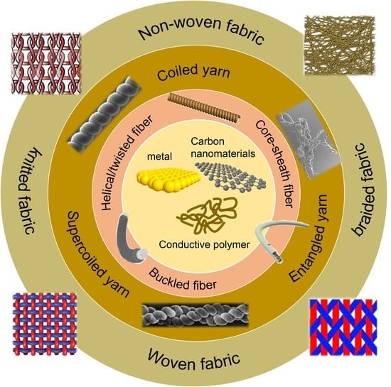
As known, textile materials can be classified as fiber, yarn, or fabric [6]. Specifically, fibers with a high aspect ratio act as element structure for the textiles. They can be further twisted into yarns, serving as the second level of textiles. Through some existing textile technologies such as weaving and knitting, yarns are leveraged to construct the third level of integration, namely, the fabrics (Figure 1). Considering the hierarchical architectures of textile materials, the overall performance of textile-based sensors is collectively determined by the interplay between the fiber properties and the geometrical or structural characteristics of their assembly at different length scales [7]. In detail, the fabric properties can be affected by several factors, including the selection of different fibers (metal, polymer, etc.), the use of various yarns (filament yarn, textured yarn, etc.), and the development of different patterns (woven, knitted, etc.). Therefore, delicate design of the microstructures and interfaces across multiple levels of hierarchy is anticipated to tailor the mechanical and functional properties of textile-based sensors.
Numerous studies have reviewed the textile sensors for wearable applications, with focuses ranging from materials, geometries or configurations, and preparation methods, to sensing mechanisms, functional performance, and electronics applications [1,2,3,4,6,8,9,10,11]. Differing from previous reviews, we paid attention to the hierarchical structural design of textile-based sensors, including the selection of constituent materials (e.g., conductive polymers, metals, and carbon nanomaterials), surface modification and shape control of fibers (e.g., twist, helix, and core-sheath), twisting and spinning of yarns (e.g., rotor-spun, ring-spun), and engineering of fabric patterns (e.g., weaving, knitting). Our study offers a guideline for the massive production of textile-based sensors with desired performance.

2. Selection of Constituent Materials
The first step for the design of wearable electronics is the selection of building blocks, which are able to afford outstanding mechanical properties without sacrificing electrical performance. In recent years, a variety of conductive materials have been extensively used to build electronic textiles, such as metal and metal oxide (nanoparticles, nanowires, and nanorods) [15,16], conductive polymers [17,18], and carbon nanomaterials (carbon nanotubes, graphene) [19,20,21,22,23,24].
2.1. Metallic Nanostructure
Thanks to the high free-electron density, metals are deemed as the most conductive materials on Earth, among which silver is the most widely studied given its highest conductivity [25,26]. However, as metal wires are relatively rigid and cannot be effectively woven into fabric, they are usually coated on polymer fibers or embedded in composite fibers. More intriguingly, when the size of metals decreases down to nanoscale, their physical properties become distinct from the bulk counterparts. This enables the metal nanostructures to be competent candidates for conductive-filled materials in textile-based sensors. Extensive studies have demonstrated the successful application of gold, silver, and copper nanowires in electronic textile devices [27]. For example, Xu et al. [28] fabricated a wearable pressure sensor based on copper nanowire aerogel monolith. By controlling the density and pore structure, the sensitivity and detection limit of sensors could be efficiently modulated. In addition, Park’s group [29] developed strain sensors with high sensitivity from the sandwiched polydimethylsiloxane (PDMS) and silver nanowire composite. The strain sensors exhibited a high piezo-resistivity with controllable gauge factors, as well as high stretchability and flexibility, which benefited the application in human body motion detection.
2.2. Conductive Polymer
Conducting polymers with π-conjugated bond structures possesses superior electrical properties comparable to metals. Besides that, they have additional advantages including light weight, transparency, intrinsic flexibility, processability, cost-effectiveness, biocompatibility, and so forth. Commonly used conductive polymers include polypyrrole (PPy), polyaniline (PANI), polythiophenes (PTs), and poly(3,4-ethylenedioxythiophene) (PEDOT) [9], which satisfy different practical requirements. In particular, polypyrrole has been widely utilized in biomedical applications, attributed to its thermal stability, biocompatibility, and biodegradability [30,31,32]. Nevertheless, it is sensitive to moisture and prone to deterioration over time when exposed to a humid environment [33]. In contrast, PANI displays high environmental stability and is the optimal choice for corrosion protection, while its non-biodegradability, low processability, and low flexibility limit its application in biological fields [34,35,36]. PEDOT is another conjugated polymer that shows higher electrical conductivity and thermal stability than PPy. When doped with a polyanion like poly-styrenesulfonate (PSS), the formed PEDOT:PSS has become the standard for conductive polymers and extensively used for flexible sensors in a number of applications [37].
2.3. Carbon Nanomaterial
Carbon nanomaterials (e.g., carbon nanotubes (CNTs), graphene and its derivatives) hold enormous potential in the application of flexible sensors. This is due to their low-dimensionality, huge specific surface area, and a collection of fascinating physical properties, including excellent flexibility, ultrahigh strength, and electrical conductivity. In detail, the elastic modulus and fracture strength of graphene were reported to be ~1 TPa and around 130 GPa, respectively [38,39,40], while the bending rigidity was only on the eV level [41]. Furthermore, its electrical conductivity and thermal conductivity reached as high as 107 S/m and 3500 W/(K·m), respectively [42,43,44]. The nanoscale size also makes them easily assembled into the macroscopic hierarchical textiles, endowing the sensor not only with high mechanical robustness and electrical conductivity but also with multifunctionality [4]. To increase the processibility of carbon nanomaterials, defect engineering and chemical functionalization are usually adopted [45,46,47]. Representative demonstrations are graphene oxide (GO) and reduced GO (rGO), where oxygen functional groups attached on the surface help avoid the agglomeration and improve the dispersion [48]. Moreover, the solution-processable GO and rGO facilitate the large-scale production of textiles.
2.4. Two-Dimensional (2D) Materials
The intensive study of graphene has drawn worldwide attention to other 2D materials as well. Some emerging 2D materials such as transition metal dichalcogenides (TMDs) [49,50,51], transition metal carbides and nitrides (MXene) [52], black phosphorus [53], and metal-organic frameworks (MOFs) [54] have been synthesized and used for the preparation of flexible sensors. For instance, MXene (Ti3C2Tx)-based textile strain sensors were constructed by Yang et al. [55], showing a high sensitivity, a wide strain range, an ultralow detection limit, and an impressive cyclic durability. In contrast to graphene, MXene presents a number of surface functional groups, which considerably increases the chemical activity and hydrophilicity, leading to a high dispersibility in solutions [56,57]. When assembled into fibrous structures, the interfacial bonding is also relatively strong beyond van der Waals interactions.
3. Microstructural Control of Fiber
Fibers act as the building blocks of textiles to create various styles of clothes through knitting or weaving technologies. They are usually prepared by a spinning method (e.g., wet-spinning and electrospinning) and present a straight configuration with limited stretchability [58,59,60]. To this end, substantial efforts have been dedicated to improving the deformability of fiber sensors while maintaining high electrical conductivity.
3.1. Helical or Twisted Structure
The creation of the helical structure of fibers affords an effective way to increase the stretchability, which can be achieved by mechanically twisting or coiling straight fibers. When the helix fiber is under tension, it is subject to a straightening process first, so that the tensile strain directly imposed on the fiber is minimized. It has been documented that the spiral-arranged textures along twisted graphene fibers improve their tear resistance and fracture toughness [61]. From a mass production perspective, twisting and coiling is also a relatively common process in industry and is simple to scale up.
Using a humidity-assisted strip-scrolling approach, Cao’s group spun freestanding GO membranes into helical fibers comprised of homogeneously distributed loops along the entire fiber length, as shown in Figure 2a [62]. Further reduction in GO could enhance the electrical conductivity to ~50 S/cm. Upon continuous elongation, helical loops were opened to accommodate large deformation, allowing rGO fibers to sustain a strain as high as 60%, as show in Figure 2b. Such a high structure elasticity favors a stable and reversible resistance change over repeated loading cycles within a moderate strain range (Figure 2c). One thing should be noted that the internal stress is inevitable during the twisting process, which can lead to stress concentration and easy damage under large deformation. Thus, the density, diameter, and charity or angle of loops need to be well controlled to balance the stretchability and the failure strength of helical fibers. To this end, Gao’s group has long been engaged in design and manufacture of high-strength graphene fibers by tuning the axial orientation, radial alignment, wrinkled morphology, and interaction strength between graphene layers [61]. Recently, they exploited a liquid crystalline wet-spinning method combined with a twisting–drawing strategy to prepare continuous helical GO fibers [63]. The obtained fibers showed superb stretchability and mechanical robustness, giving rise to high stability and reversibility over multiple operation cycles.
Chen et al. [64] prepared conductive hollow fibers with helical microchannels filled with ion liquid, followed by sealing with PDMS, as depicted in Figure 2d. The electronic properties of these two kinds of fibers are presented in Figure 2e. Different from the straight conductive fiber (SCF) showing a high strain sensitivity, the helical conductive fiber (HCF) was observed to display a strain-independent conductivity because of the elongation of the helical structure instead of straining of fiber when subjected to 100% strain. Both SCF and HCF demonstrated an excellent working durability and long-term stability during 10,000 cycles at 50% strain (Figure 2f). It is clear that SCF featuring fast responses to strain and pressure could well detect human motion and capture the signal language. By comparison, the helical configuration may not be suitable for the design of strain sensors, considering its low sensitivity and narrow strain range less than the maximum sustained strain; instead, HCF can be a promising candidate to replace the industrial wires in circuit.
3.2. Core–Sheath Structure
The design of coaxial fibers provides an alternative pathway to gain higher stretchability. Coaxial fibers commonly include a conductive core wrapped by an elastic shell. Distinct from the twisting structure, the core–sheath structure offers a shorter ion transport path and a higher stability upon external loading due to the strong interface bonding within the layer-by-layer configuration [65].
The coaxial wet-spinning assembly method has been proposed to produce polyelectrolyte-covered graphene fibers. For example, a one-step coaxial wet-spinning assembly method was developed to prepare silicone elastomer-coated CNT core-sheath fibers as wearable strain sensors, as depicted in Figure 3a [66]. By augmenting the CNT content, the conductivity was enhanced by several orders of magnitude, suggesting that a continuous conductive network was formed (Figure 3b). The obtained fiber strain sensors were found to have a tolerable strain of >300% and a gauge factor of 1378 (Figure 3c). Higher CNT content also gave rise to a slower resistance change under strain. In addition to high stretchability, outstanding stability was achieved simultaneously, evidenced by the reversible resistance change over >10,000 cycles. Benefiting from the bending- and torsion-insensitiveness, coaxial fiber strain sensors could precisely detect subtle human motions. Through a coaxial wet-spinning process, Zhou et al. [67] fabricated a fiber-based strain sensor in a core–sheath configuration consisting of a thermoplastic elastomer (TPE) wrapped with CNTs, as depicted in Figure 3e,f. The fragmentation of the coaxial fiber was observed during stretching (Figure 3g), implying good load transfer efficiency between the CNT core and the TPE matrix, and could be nearly recovered upon unloading. Such cracks are critical to the stretchability of the fibers and allow the linear resistance response. The consequent fiber sensor had a high sensitivity (~425) for the strain range up to 100%, as well as high mechanical stretchability and stability, showing great potential as the sensing components in wearable textiles.
Similarly, by coaxial wet-spinning of GO with aramid nanofiber (ANF), the core–sheath structured graphene fibers were prepared for the application of wearable electronics [68]. The addition of ANF as the sheath not only increased the strength of the graphene fiber but also imparted excellent flexibility and weavability. Compared to the pure graphene fibers, the fracture strength and failure strain was increased by 80% and 700%, respectively. The high thermal resistance of ANF also allowed for direct thermal reduction in GO, followed by incorporation of graphene nanoplatelets. Consequently, the electrical conductivity was elevated up to ~15,000 S/m. More recently, Gao et al. [69] employed the coaxial extrusion 3D-printing technology to fabricate wearable sensor arrays composed of pressure and strain sensors. The sensor array presented a pressure sensitivity of 0.562 kPa−1, a high detection limitation (3 Pa), a rapid response and relaxation speed (230 ms), and superior durability (>10,000 cycles). Different mechanical loading such as twisting, bending, and shearing could be accurately captured.
3.3. Buckling Structure
Introducing buckling structure via the pre-stretch-and-release method has been manifested as a facile way to realize the high stretchability and flexibility in electronic devices [70,71]. Similar to helical configuration, the buckling structure is flattened first under tensile loading, thus giving rise to a stable conductance during deformation. According to the literature [3,6], a buckling structure can be created in either conductive core fibers in TPE or conductive coating materials wrapped on pre-stretched elastomeric fibers.
For example, Baughman’s team developed a fiber-based strain sensor by depositing CNT films onto a rubber fiber [72]. The fiber core was pre-stretched to a 1400% when wrapping CNT, which was oriented parallel to the axial direction (Figure 4a). As a result, from the SEM images in Figure 4a, short and long buckling periods are respectively observed in both the axial and belt direction. Further coiling of the fiber greatly increased the strain range and quality factor up to 2470% and 526, respectively (Figure 4b). Nonetheless, the relatively large diameter of the rubber core (2 mm) resulted in a high core-to-sheath volume ratio, accounting for a low electrical conductivity. The strain sensor hence could only be activated by a high drive force. In this case, a downsized core–sheath conducting fiber in a diameter of 40 μm but the same sheath thickness was then designed to improve the electrical conductivity [73]. When the diameter of the fiber core decreased, the spacing between the buckles tended to increase. This led to a reduction in or even elimination of the contact between neighboring buckles in the lateral direction during compression of the sheath–core fiber. In addition, the fiber conductance was almost independent of the strain due to the buckling structure; therefore, the conductivity rose quadratically with fiber length as shown in Figure 4c. It was found that the fiber conductor displayed a substantial enhancement in conductivity when being stretched, close to the theoretical limit denoted by the dashed line, suggesting a negligible resistance change during the deformation.
More recently, a worm-shaped fiber sensor was fabricated by depositing caterpillar-structured graphene layers onto polyurethane (PU) fibers, as illustrated in Figure 4d [74]. Such a worm-shaped fiber deformed in reminiscence of the creep behavior of worms. Consequently, the maximum strain could reach 1010% with a large electro-response range (~815%), excellent conductivity (124 S/m), and a long-term durability (>4000 cycles). To interpret the electrically conductive performance of the worm-shaped graphene coating, the authors proposed a geometrical model as presented in Figure 4e. Concretely, the stretching process could be divided into three stages, which were separated by two boundary points: (1) contact critical point at which two legs of the graphene and PU loop were in point-contact; and (2) straightened pre-stretched state where the strain matched with the pre-stretched state. The model fit well for the results of measured electrical conductivity of worm-shaped fibers.
Wei et al. [75] also constructed multiscale wrinkled features on the pre-strained waterborne PU fiber by writing in silver nanowire ink using a brush pen, as shown in Figure 4f. The wrinkle size could be clearly captured in SEM, showing a uniform coverage and distribution (Figure 4g,h). The resultant core–sheath conductive fibers exhibited high conductivity and extendibility. Furthermore, the fibers were twisted to build a flexible piezoresistive sensor, giving rise to a high sensitivity to the bending and pressure. This was ascribed to more contact points resulting from the wrinkled microstructures, which caused a considerable change in interface resistance when subjected to external loading, as depicted in Figure 4i.
Based on a “solution stretching–drying–buckling” process, Zhou et al. [76] prepared stretchable coaxial fibers via a designed self-buckling behavior of conductive polymer micro-ribbons incorporated in a TPE sheath, as shown in Figure 5a. In particular, polyethylene-block-poly (ethylene glycol) (PBP)/PEDOT:PSS was wet-spun into the core fiber. By controlling the applied pre-strain, the maximum failure strain could be tailored across a large range. As presented in Figure 5b, when a 900% pre-strain was imposed to fiber, the maximum failure could be enhanced up to ~675.8%. Thanks to the buckling structure and the elastic TPE sheath, no obvious change was found for the cross-section of conductive ribbon so that the electrical resistance of fiber sensor kept almost constant during the tensile deformation until the buckled structure became fully unfolded (Figure 5a), hence increasing the stability of electrical conductivity. The maximum ΔR/R0 for the strain sensor under the cyclic loading was only 0.031% at the pre-strain of 900%, which kept almost constant with increasing cycles (Figure 5c,d). From Figure 5e,f, it is obvious that increased loading of PBP in the PEDOT:PSS/PBP fiber helped to improve both the conductivity and ductility of the core fiber. In addition, the elastic modulus was reduced so as to generate buckles at a lower strain level. The effect of microstructures on the electrical performance of conductive fibers are summarized in Table 1.
4. Configurational Engineering of Yarn
Yarn is defined as an assembly of a bunch of fibers held together through the insertion of twist to form continuous strands. From the structure point of view, typically, there are three main technologies involved in the production of yarn [77]: (1) Yarns are produced by placing the fibers in parallel that are bonded together via mutual frictional forces. Given the weak friction resistance dominated by van der Waals forces, the tensile loads imposed to the yarn easily induces mutual slippage when the yarn suffers from severe bending or twisting deformation. This is an irreversible process that can cause easier failure at low strains and faster degradation of conductivity. (2) Densely aligned CNT bundles can be prepared by twist spinning, typically showing a high conductivity of 300 S/cm) and high strength of more than 100 MPa, whereas the interfibrillar slip phenomena are still inevitable. As a result, the sensitivity of the helical fiber strain sensors is relatively low and strain range is also lower less than the maximum sustained strain. (3) In light of the limited stretchability of straight or twisted yarns, substantial efforts have been directed towards configurational engineering by introducing multiply or coiled structures via overtwisting the yarns under tension (Figure 6) [78]. The widely demonstrated examples are the spring-like CNT yarns which show impressive stretchability while retaining high electrical conductivity. Considering the one-dimensionality and high flexibility, CNTs have been extensively constructed into yarn structures to fabricate flexible sensors, which is the focus in this section.
4.1. Coiled Configuration
Leveraging high flexibility of CNTs, Cao’s group [79] demonstrated the controlled fabrication of a yarn-derived spring-like CNT rope, where the loops were uniformly arranged as shown in Figure 7a. Inside each loop, the CNT bundles were observed to twist with slight alignment (Figure 7b). These CNT ropes exhibited outstanding axial stretchability up to strain of 285% by loop unfolding and straightening during the stretching. Accordingly, the fracture toughness was also as high as 28.7 J/g. More importantly, the electrical conductivity of such CNT yarns was nearly 440 S/cm at the initial state and no degradation was noted after repeated loading cycles (Figure 7c). Later on, Cao et al. [80] modified the spinning strategy and accurately controlled the loop position and number, and successfully fabricated a partial-helical structure, as shown in Figure 7d,e. In contrast to the fully helical configuration, the partial one exhibited a better elasticity up to the strain of 25% as well as a linear resistance–strain relationship that is important for strain sensor applications (Figure 7f).
In another report, Gao et al. [81] prepared helical CNT and PU composite yarn adopting hierarchical structure design principles (Figure 7g). Leveraging the interlaced conductive CNT networks on the microscale as well as the macroscopic helical structure, the synergistic effect between mechanical properties and helical structures accounted for the ultrahigh elasticity. Beyond that, they reported an impressive recoverability of electrical resistance when the strain was within 900%; the maximum tensile elongation could reach as high as 1700%. In addition, the strain sensor prepared by twisting the CNTs into a yarn can present a good conductivity and hence a rapid response.
4.2. Two-Ply Coiled and Supercoiled Configuration
In order to further improve the strain range and failure limit, Cao’s group [82] proposed a two-level hierarchical composite structure composed of double-helix CNT yarn segments (Figure 8a). As presented in Figure 8b,c, during the stretching process, a two-stage fracture behavior could be observed, which gave rise to higher tensile strain and effectively delayed the failure process. When the first yarn fractured at around 75% strain, the resistance of double-helix CNT yarns exhibited a sudden change as shown in Figure 8c; after that, it kept increasing steadily until the eventual failure at around 170% strain. Apparently, such a hierarchical design would prolong the service lifetime of the double-helix CNT yarn-based sensors. Moreover, the toughness could be significantly enhanced to guarantee the device stability (Figure 8d).
In the reminiscence of the supercoil conformation of DNA in a twist of a double helical axis, the supercoiled fibers were prepared by overtwisted insertion of spandex fibers wrapped in CNT-spun sheet with surface wrinkles, as shown in Figure 8e,f [83]. Typically, the first-coiled yarns can only sustain < 400% strain, while two-ply coiled yarns were observed to have a stretchability of 800% [84]. Son et al. found that, as supercoiled yarn had a highly compact and ordered structure, a large amount of elastic strain energy could be stored in the fiber, enabling the fiber to show a superelasticity of ~1500% without significant electrical fracture. As show in Figure 8g, during the stretching process, the yarn mainly experienced gradual opening of first coils at the low strain range (<450%) and the supercoils. At the higher strain levels (>450%), the wrinkled structures tended to be unfolded which further contributed to the stretchability of yarns.
4.3. Entangled Configuration
In addition to the coiled or double-helix yarns with relatively regular configurations, extreme overtwisting can produce entangled CNT yarns with a higher complexity [85]. As shown in Figure 9a, with increasing overtwisting, the straight yarn gradually self-assembled into single-helix and then double-helix structures and finally developed random at multiple sites along the yarn axis while intertwining to generate amorphous configurations. An aggregation containing multiple self-interlocked twists were eventually generated, as shown in Figure 9b. Such an entangled yarn structure was highly stable and could be stretched to 500% strain (Figure 9c), with no change of resistance when disentangled. According to the stress–strain curves in Figure 9d, multiple stress peaks were visible, corresponding to the resolving events of the double-helix segments within the entanglement. In addition to the large sensing range, the entangled coiled CNT yarn presented a cyclic stretching–releasing stability at 500% strain for 600 cycles, as depicted in Figure 9e. The configuration dependent sensing performance of conductive yarns are summarized in Table 2.
5. Pattern Design of Fabric
A fabric structure is made by the interlacement of yarns or intermeshing of the loops to act as 2D flexible materials [86]. The engineering design of patterns applied to smart textiles are based on mature textile manufacturing and garment assembly routines, such as knitting, weaving, braiding, embroidery, and sewing (Figure 10a). From a mechanical and structural perspective, different fabric structures are entirely dissimilar to each other. For instance, the yarns in woven pattern are nearly immobile and form a dense and stable structure, so that the fabric is almost inextensible with limited deformations in the yarn structure (Figure 10b). By comparison, the interlocked loops in a knit pattern usually deform and slide readily, giving rise to a high stretchability with significant changes in small-scale structure [87,88]. From the application perspective, each fabric manufacturing technique has its own pros and cons in light of specific substrate properties, of which the selection depends on the end-use of the electronic textile.
5.1. Weaving
The most commonly used are the woven fabrics, consisting of yarn interlacements mutually in orthogonal directions [90]. The length, frequency, and distribution of interlacements in a woven fabric structure collectively decides its mechanical and functional characteristics. The above parameters are critical to the electrical performance as well since the consecutive points in interlacements influence the electrical contact [91]. According to the weave patterns, woven fabrics can be classified into plain weave, satin weave, twill weave, and so on, which can satisfy the needs of different applications.
Using Ni-woven fabrics as templates, Liu et al. [92] synthesized freestanding graphene woven fabric (GWF) by the chemical vapor deposition (CVD) method, which was then transferred onto precured PDMS film to prepare the composite sensor (Figure 11a). It was found that the GWF and PDMS composites with thick graphene tubes showed a stable and regular mesh configuration after the mechanical transfer; by contrast, thinner graphene tubes were prone to shrinkage and generated a wavy structure during transfer, as presented in Figure 11b, thus having a much lower sensitivity than those with thicker graphene tubes. As a result, the conductivity and gauge factor of the obtained fabric could reach 2.73 S/cm and 223, respectively, at a strain of 3%. An excellent durability was also achieved under 1000 stretch and release cycles. Similarly, Zhao et al. [93] employed the same method to prepare a synergistic temperature–humidity sensor from GWF with crisscrossed interlacing graphene micro-ribbons, allowing for a ultrahigh sensitivity within a strain range of 2%.
The woven composite fabric has been alternatively constructed from composite yarns where graphene is coated on nd woven wearability.
Yin et al. [95] reported an facile, efficient, scalable, and cost-effective way to prepare GWF sensors. They performed the dip coating of GO on the cotton bandage as the template with macro-level woven-fabric geometrical conformation, followed by the reduction in GO as well as the pyrolysis treatment of the cotton bandage in an ethanol flame. SEM images in Figure 11e present the rGO-woven fabric sensors, where the framework was built by warp and weft yarns, forming crisscross interlaced patterns with uniformly arranged rectangular holes. Under a higher magnification, it could be seen that the yarn included a bundle of twisted fibers with a wrinkled surface. Benefiting from the hierarchical structure, a high stretchability up to 57% strain together with a high sensitivity (gauge factor of 416 for the strain range of 0–40% strain and 3667 within 48–57% strain) was obtained for the GWF strain sensor.individual fibers. In the work led by Cui et al. [94], composite yarns were prepared by helically winding an elastic thread with core-spun yarns. These multifilament yarns were obtained through electrospinning GO-doped PU nanofibers onto the Ni-coated cotton yarns, as shown in Figure 11c. The former actually acted as dielectric layers while the latter were the conductive electrodes. The pressure sensing mechanism is illustrated in Figure 11d. Upon loading, it was found that the dielectric layer and the electrode both increased the permittivity; correspondingly, the change in volume caused the distance variation between the electrodes, implying an excellent pressure sensitivity. Even under a low external load, the sensor unit exhibited superb sensing performance: a high sensitivity of 1.59 N−1, a broad sensing range, a short response time, and a low detection limit. The helix feature of the composite yarn further granted the sensor unit with a high stretchability, a good cycling stability, a
Inspired by the flexible and stretchable spider web, Liu et al. [96] developed a wearable GWF composite sensor via filling PDMS into the hollow graphene tubes within GWF film, which was then half embedded into a partially cured sticky PDMS film to enhance the linearity and structural stability (Figure 11f). The strong bonding between GWF and PDMS ensured efficient load transfer at the interface and hence excellent stretchability. As shown in Figure 11g, upon stretching, the surface wrinkles on the graphene tubes were first flattened; further increasing the applied strain above 10% led to the occurrence of microcracks, which were growing with increasing strains in the loading direction. Consequently, the contact between the graphene layers declined, accounting for an increase resistance as well as a higher piezoresistive sensitivity. More importantly, these deformation processes were totally reversible upon unloading, ensuring the sensing stability of the composite sensor during cyclic loading. Therefore, it was concluded that the infiltrated PDMS core in the graphene tubes protected the conductive networks and improved the sensing capability, as well as providing high repeatability and reliability to the flexible device, allowing long-term service.
5.2. Knitting
Different from weaving, knitted fabric is created by interlocking loops of neighboring threads [97]. In contrast to woven fabrics that require elastic yarn with accessible extension < 10%, knitted fabrics offer high elasticity and can develop large extensions as high as 100% even based on non-elastic yarns. As mentioned above, although the stretching deformation of knits that involves a flattening of yarn loop curvature usually quickly recovers, the further deformation beyond such elastic stage would lead to yarn sliding against each other, which cannot be recovered immediately. The relevant energy dissipation accounts for higher fracture toughness and impact resistance of knitted fabric compared to the woven fabric.
To improve the durability and fatigue resistance, Zeng et al. [98] adopted textile knitting technology for the preparation of fabric electrodes. The fabric was made of a PU yarn as the core wrapped by silver-coated PA yarns. The loop structures in the plain knit helped reduce the strain in fibers and increase the fatigue life against cyclic loading. The stretchability was reported to be as high as 250% with a low elastic modulus as low as ~0.05 MPa. The resistance was also kept stable at 30–33 Ω when subject to compression of 2727 cycles.
Compared to the continuous film-based flexible sensor, knit pattern design of fabric can simultaneously improve the mechanical and electrical performance at high strain region. In a recent work, Ma et al. [99] synthesized conductive stretchable fibers made of Ag particles, CNTs decorated with Ag particles, and poly(vinylidene fluorideco-hexafluoropropylene) (PVDF-HFP) substrate. These fibers were then constructed into a two-ply rope, four-ply rope, and weft knitted fabric (Figure 12a). Obviously, the stretchability of ropes was higher than the single fiber in Figure 12b, while the increase in the resistance tended to be more sluggish with more plies of ropes. In contrast, for the weft knitted fabric, the resistance change was insignificant below 200% strain. This could be explained by the intimate contact at the stitch cross section of the knit structure. They further demonstrated that additional coating of PDMS on fibers and fabrics could facilitate the mechanical stretchability and electrical stability within a broad strain range of 100%.
More recently, Seyedin et al. [100] demonstrated a scalable production of PU/PEDOT:PSS multi-filaments in a kilometer scale. To tune the strain sensing behavior of the textile-based sensors, they designed fiber in different patterns including the plain knit, co-knit, co-knit with conductive stitch, plain knit with non-conductive stitch, and co-knit alternate, as shown in Figure 12c. The overall sensing mechanism was governed by both the resistance change of the fibers and the configurational transition in the fabric. In Figure 12d, it can be found that all five textile prototypes effectively sensed strains up to 200 with no evidence of structural damages. In particular, the plain-knit pattern represented the ideal case, where configurational changes in the textile dominated the sensing performance, whereas the conductive filaments were likely less to be stretched. In contrast, having a compact structure, a co-knit pattern of fabric resulted in the filament elongation governing the stretching deformation. In terms of the gauge factor, a plain knit pattern gave a negative value of −0.3 at 200% strain. Although the sensitivity tended to be higher for the plain knit with non-conductive stitch, it showed a lower sensing response recovery than plain knit. Furthermore, it was demonstrated that the presented sensors kept stable for up to 500 cycles after running 50 cycles.
5.3. Non-Woven
A non-woven textile is produced by the physical or chemical bonding of fibers without any restriction. Both staple and filament fibers from different generic groups can be used to produce the non-woven fabrics (NWF). Apparently, the properties of NWF depend on the selection of fiber materials, the arrangement of fibers, and the bonding types and intensity. So far, some studies have demonstrated the application of NWF in wearable sensors, leveraging its specific functions including softness, resilience, flame retardancy, washability, and so forth.
By coating the conductive cellulose nanocrystal and graphene on the thermoplastic polyurethane (TPU) NWF, a flexible strain sensor having large sensing range and high sensitivity was successfully fabricated [101]. In particular, polydopamine (PDA) was used to treat the fabric firstly to strengthen the interface between the coating and fabric, and subsequent immersion in hydrophobic-fumed silica (Hf-SiO2)/ethanol dispersion granted the fabric with superhydrophobicity (Figure 13a). The as-prepared composite NWF sensor was based on a micro-crack sensing mechanism, as shown in Figure 13b. As a consequence, NWF sensor with denser cracks presented a lower gauge factor and a wider sensing range. When the graphene content was 25 wt%, a broad working range (98%), a low detection limit (0.1%), short response time (33 ms), and good durability over 1000 cycles were obtained simultaneously. Furthermore, the superhydrophobicity of NWF strain sensor enabled great waterproofness and hence corrosion protection and self-cleaning ability. In another study, Wang et al. [102] reported a GO-coated NWF humidity sensor. Likewise, bovine serum albumin (BSA) was introduced as an interfacial layer to allow more GO absorbed on the NWF (Figure 13c). The as-obtained sensor exhibited a fast response recovery to achieve high sensitivity, which favors its application in the detection of human respiration. Cho et al. [103] demonstrated the fabrication of conductive NWF through blow spinning of PVDF-HFP blended with CNTs, as shown in Figure 13d. The NWF sensor showed a high gauge factor of 134, a detectable strain of as low as 0.03%, and good mechanical stability within 1000 cycles. The brief summary of the fabric patterns and corresponding output performance of textile-based sensors can be seen in Table 3.
6. Coating Technology
The simplest way to manufacture textile-based sensors is spinning conductive fibers and yarns, followed by weaving and knitting. Alternatively, coating of conductive materials on fiber, yarn, or fabric affords another facile and efficient approach for the large-scale production of electronic textiles. Commonly used coating methods include in situ polymerization, vapor-phase polymerization, dip coating, spray coating, vacuum filtration, and rod coating.
Chemical polymerization is suitable for making fabrics coated with conductive polymers such as PPy and PEDOT:PSS. A common practice is soaking the fabric in a solution containing the monomer, the oxidant, and the dopant to initiate the polymerization process. For example, Lycra fabric-based stretchable and conductive sensor was prepared by coating a PPy layer using a chemical polymerization method [104]. In contrast, vapor-phase polymerization provides a higher homogeneity of coating than chemical polymerization. Therein, the textile substrate is immersed in a solution of oxidant and dopant and then exposed to the vapor of the monomer to form the polymer layer. As a result, the sensitivity is higher but the sensing range is lower compared to the fabric coated with the in situ polymerization method [105]. Dip coating represents a simple way to prepare the conductive textiles. Soaking a Spandex fabric in aqueous PEDOT:PSS dispersion was demonstrated to endow the fabric with an electric conductivity of 0.06 S/cm [106]. Multiple dip coating can further increase the conductivity up to 1.7 S/cm; however, over-coating would lead to the interfacial delamination failure which has a negative effect on the electric performance. Spray coating has an advantage of better thickness controllability compared to dip coating. Lee et al. [107] assembled functional hybrid carbon nanomaterials and piezoresistive ZnO nanowires on a PET fabric by spray coating. The resultant fabric sensor could sense low bending strains of up to 6.2% with a gauge factor of 7.6, both higher than that of counterpart film.
Although surface coating can produce textile-based sensors with high sensitivity and relatively high sensing range, there remain some challenges in achieving high linearity and cycling stability due to the potential weakness at the interface between the coating and textile substrate. Interfacial failure is easily induced during the repeatable deformations and causes the catastrophic failure of devices. While conductive polymer composite typically results in a higher adhesion to the textile substrate, the overall conductivity might be impaired due to the presence of non-conductive polymers in the coating layer [108].
7. Applications
7.1. Human Motion Detection
Textile-based sensors are advantageous in skin affinity and integrability with human skin, gloves, and clothes, thus enabling remote manipulations with safety and comfortability. Zhang’s group has developed a stretchable and wearable strain sensor by carbonizing silk [109] and cotton [110] fabrics as the electrodes (Figure 14a). It was demonstrated that the plain-weave pattern gave rise to the best performance, showing high sensitivity, fast response, wide sensing range, as well as excellent durability. Such superior performance was attributed to the hierarchal network structure. The obtained fabric sensors were able to monitor both large and subtle human motions (e.g., jumping, marching, jogging, bending, rotation of joints phonation, pulse, facial micro-expression, and respiration), as illustrated in Figure 14b. In addition, they developed a dry-Meyer-rod-coating process to coat graphite flakes on the silk fibers to prepare for the fabric strain sensor [111]. The overlapping area between the graphite flakes changed during the cyclic loading process, endowing the as-resulted sensor with outstanding performance with fast response, long-term stability, small hysteresis, and low drift. Furthermore, the proposed dry-Meyer-rod-coating method was facile and versatile, which can be extended to other core fibers for the preparation of sheath–core fibers, such as polypropylene (PP) fiber and Spandex fiber.
7.2. Touch or Pressure Sensor
In addition to strain sensors that can monitor the body motion as discussed above, electronic textiles have also been made into touch- or pressure-based input devices in wearable electronics [112]. For instance, Ma et al. [113] adopted a facile and continuous electrospinning technology to prepare an ultralight single-electrode triboelectric yarn with helical hybridized nano-micro core-shell fiber bundles on a large scale. The fiber consisted of PVDF/PAN hybrid shell and the core of sliver yarns, which showed high triboelectric output (Figure 15a). The plain fabric woven triboelectric textile could deliver electrical outputs of 40.8 V, 0.705 µA/cm2, and 9.513 nC/cm2 under pressure of 5 N with 2.5 Hz, showing high sensitivity for monitoring subtle contacts from humans and insects. Fan et al. [114] reported a textile-based sensor with a cardigan stitch texture, which allowed enhanced triboelectric interaction between Nylon yarn and stainless steel yarn. The prepared sensor exhibited a pressure sensitivity of 7.84 mV/Pa, fast response time of 20 ms, high working stability over 100,000 cycles, wide working frequency bandwidth up to 20 Hz, and impressive machine washability (>40 washes). It could be stitched into garments, monitoring of arterial pulse waves and respiratory signals at the same time (Figure 15b). Lee et al. [17] prepared a conductive fiber via coating poly(styrene-block-butadienstyrene) (SBS) polymer and Ag nanoparticle composites on the surface of Kevlar fiber, as shown in Figure 15c. Further coating of PDMS as dielectric layers on surface and stacking the two PDMS-coated conductive fibers perpendicularly to each other produced a capacitive-type pressure sensor. Such a pressure sensor featured a high sensitivity (0.21 kPa−1) in the low-pressure region, fast response time less than 10 ms, and high stability >10,000 cycles with insignificant hysteresis. Utilizing the weaving method, the textile-based pressure sensor could be integrated into a multipixel array configuration in the form of fabrics and imbedded into gloves and clothes, enabling remote control of machines as human–machine interfaces.
7.3. Energy Harvest
In light of the threats of the energy crisis and environmental pollution, the desire for renewable and environmentally friendly energy solutions is growing for sustainable development of human civilization. Combining electronics with textiles has provided a revolutionizing way to harvest energy from the human body and its surroundings. Representative examples include triboelectric nanogenerators, piezoelectric nanogenerators, thermoelectric generators, and so forth [115,116]. Zeng et al. [98] demonstrated an all-fiber-based piezoelectric nanogenerator for harvesting mechanical energy in textiles, consisting of a PVDF–NaNbO3 nanofiber non-woven fabric sandwiched between two conducting fabric electrodes. The obtained nanogenerators showed, respectively, an open-circuit voltage and current of 3.2 V and 4.2 mA at a pulse pressure of 0.2 MPa. The power generation was also reliable during the cyclic testing that simulated human walking. A washable skin-touch-actuated textile-based triboelectric nanogenerator was prepared by Xiong et al. for harvesting biomechanical energy from both voluntary and involuntary body motions [117]. In particular, black phosphorus encapsulated with hydrophobic cellulose oleoyl ester nanoparticles worked as an electron-trapping coating, endowing the textile nanogenerator with long-term reliability and high triboelectricity even under extreme deformations, severe washing, and extended environmental exposure. Maximum instantaneous output electricity up to 880 V and 1.1 µA/cm2 could be obtained by touching with a small force (~5 N) and low frequency (~4 Hz). More examples of smart textiles that were designed to harvest body heat energy, biochemical energy, solar energy, and hybrid energy forms were comprehensively reviewed previously [115].
8. Future Perspective
8.1. Wearability
The wearability requirements typically include washability, breathability, and biocompatibility, which is essential to widespread marketability [118]. As textile materials are easily damaged due to washing or sweating under high moisture [119], electronic textiles are required to be robust enough against washing. In this regard, designing compact fabric structures, for example by lamination, is considered as an approach to protect the textile materials. Mounting superhydrophobic surfaces on the textiles could resist surface contamination in practical situations [115]. The washability of fabric sensors may also be optimized by PU sealing or pre-treatment with PDMS as well [120,121,122]. A self-cleaning coating layer as a barrier is recommended to protect textiles as well as microcircuits by preventing water penetration. Breathability or air permeability that refers to the ability to allow transmission of moisture and air is another key factor to guarantee the wearing comfort of wearable electronics, where the textile-based design plays a critical role. Controlling the volume between the interlaced yarns to tune the porosity and modulating the size of embedding functional materials could be potential solutions. The use of wool and cotton can help absorb perspiration and release heat simultaneously, improving the ventilation of skin and the ambient environment. To achieve a high breathability, Lee et al. [123] fabricated a flexible and lightweight thermoelectric yarn based on electro-spun PAN nanofiber cores that were coated with n-type/p-type semiconductor sheaths linked by gold interconnects. The yarns could be knitted and woven in series or in parallel with a zigzag, garter-stitch, or plain structure. Considering the long-term epidermal applications of wearable electronics, biocompatibility of smart textiles has become a serious concern worthy of attention. Some risks exist in terms of the leakage of toxic chemicals in current textile generators, especially those containing metals or dyes [124,125]. Therefore, it is urgently required to find some toxic-free materials as the replacement, such as natural polymers (like cellulose).
8.2. Functionality
Soft polymers and 2D materials used for smart textiles are susceptible to various types of damage, including fatigue, overloads, interfacial debonding, and cuts, tears, and perforations by sharp objects [126]. One economic and ecological solution is to construct fiber or fabric out of self-healing polymers, incorporating the intrinsic ability to heal microscopic and macroscopic damage, either fully autonomously without the need of any external intervention or by means of an external stimulus, for example, heat or light [127]. Shuai et al. [128] developed a continuous dry-wet spinning method to manufacture stretchable, conductive, and self-healing hydrogel fibers. The physically crosslinked poly (NAGAco-AAm) (PNA) hydrogel precursor presented a thermally reversible sol-gel transition that ensured the success of the spinning process. The self-repairability came from the existence of abundant dynamic hydrogen bonding and the healing efficiency could be improved by heating. It was demonstrated that a healed net could be generated when splicing short PNA hydrogel fibers into a network and kept for a while at 45 ℃, which was robust to carry an object of 20 g. With the elastomeric poly (methyl acrylate) (PMA) coatings, the core–sheath fiber was prepared featuring a high strain sensing capability, which could be further weaved into triboelectric nanogenerator for energy harvesting. On the other hand, shape memory effect has been deemed as an effective approach to heal the irreversible deformation, which enables the electronics to recover to their original state from a deformed shape, greatly extending their service time. Yang et al. [129] prepared an anisotropic conductive knitted fabric-based composite by encapsulation of polyurethane (PU). Specifically, a shape memory PU substrate was used to respond to the human body temperature as a thermal stimulus. The conductive knitted fabric and PU-sensing device exhibited a good repeatability and could be spontaneously healed during routine wearing without any special care. Moreover, self-healable PDMS elastomers also offers the opportunity to address such an issue if they are made into fibers and fabrics [130].
Magnetic fabric materials have been gradually explored for wearable electronics in recent years [131,132,133]. Magnetoelastic effect, commonly found in metals or alloys, was discovered in soft materials by Chen’s group [134]. This can be leveraged for the design of wearable electronics based on a new biomechanical-to-electrical energy conversion mechanism. In principle, magnets (e.g., NdFeB) were uniformly distributed in the polymer matrix, which can be polarized under an impulse magnetization, to form a wavy chain-like arrangement. Upon applying an external pressure, magnetic particles were driven to move and rotate so that the magnetic flux density of the soft material was changed. By merging such a soft magnetoelastic system with a coil, a magnetoelastic generator was developed to convert the magnetic flux density variation into electricity. For instance, Chen et al. [135] fabricated a textile-based magnetoelastic generator by sewing a soft magnetoelastic film with a textile coil. The expansion and contraction of the chest caused by breathing deformed the magnetoelastic generator and distorted the magnetic field, inducing a current output. Accordingly, the prepared breath sensor exhibited a high sensitivity of 0.27 mA/kPa, a signal-to-noise ratio of 61.8 dB, and a response time of 15 ms. Different from the layer-stacking configuration, the same group later invented a textile magnetoelastic generator via weaving the magnetoelastic fibers with conductive yarns to couple the observed magnetoelastic effect with magnetic induction (Figure 16a–c) [136]. The textile magnetoelastic generator presented a short-circuit current density of 0.63 mA/cm2 and an internal impedance of 180 Ω. Furthermore, the design parameter of weaving pattern was found to impact the electric performance of the sensor. Specifically, the textile with the plain-weave pattern showed the highest electrical output, followed by that of the satin-weave-patterned textile, while the twill-weave pattern gave the lowest output current and voltage (Figure 16d and e) because of their different structure-induced deformation degree in response to a fixed mechanical stress.
More recently, Dong et al. [137] proposed that 3D fabrics outperformed 1D fibers and 2D fabrics in terms of electromechanical conversion performance, providing a powerful combination platform for multifunctional integration. The 3D fabrics with tunable stacking layer in thickness direction can not only realize efficient acquisition and synchronous storage of multiple energy forms but also give rise to real-time response and self-powered sensing of multi-mode pressure signals. It is capable of making full use of the energies around the human body, such as mechanical energy and temperature gradient. In this case, 3D printing can enable facile, inexpensive, and rapid fabrication of complex composite structures with heterogeneous functional properties without the use of molds [7].
8.3. Scalability
Despite significant progress achieved in the development of textile-based sensors, more and more attention in this field has been turned to the fast industrialization and commercialization, beyond the simple demonstration of conceptual devices. While high-performance unit textile-based sensors have been extensively fabricated in the laboratory, it is of great concern to develop cost-effective processes for the large-scale fabrication in industry. Some large-scale productions of conductive fibers have been realized to enable the fabrication of functional fabrics for sensing applications. For instance, a high-speed rope braiding machine was utilized to fabricate core–shell triboelectric braided fibers with uniform thickness and continuous length, which could be further expanded to power textiles based on different fabric forming techniques, to realize energy harvesting and self-powered sensing functions (Figure 17a) [138]. In addition, Seyedin et al. [100] developed a wet-spinning line equipped with a pressure-controlled formulation vessel, a 100-hole spinneret connected to a high precision metering pump, temperature-controlled coagulation bath (1 m long) and washing baths (∼1.2 m long), a heating column, and a winding unit, as shown in Figure 17b. It allowed the continuous production of conductive elastomeric multifilament in a kilometer scale.
Although the machine weaving technology is mature for the production of textile materials on an industrial scale, the mass and cost-effective production of conductive materials with high quality as well as the integration technology of the unit devices are urgently required for practical applications. For example, in terms of graphene production, liquid-phase exfoliation appears promising for “laboratory to industry” translation. Specifically, high-shear mixing of graphite was shown to be more efficient than sonication which can be scaled-up to an industrial level [139]. The exfoliation can be achieved in liquid volumes up to hundreds of liters. In fact, many companies involved in the carbon business have already claimed the production capabilities of thousands of tons per year [140]. On the other hand, fully printing technique, which can be used to fabricate large-scale sensor arrays, represents a promising method for flexible sensors [115,141].
8.4. Stability or Durability
Long-term working stability or durability is always a concern of textile-based sensors when working in a harsh condition [142,143,144] because they are constantly subjected to mechanical deformation, including stretching, bending, twisting, pressing, scratching, and so on, which may cause damage and malfunction. As discussed above, a compact fabric structure design would be helpful to protect the textile materials from destructions. In addition, the use of wear-resistant coating and packaging can also enhance the long-term stability and durability, through different approaches including thermal drawing, wet-spinning, melt-spinning, spray coating, and screen printing have been adopted. Improving the surface roughness of fabric structures facilitates larger loading areas, favoring coating functional material via a solution process. The interfacial adhesion also plays a vital role during the packaging process, wherein interface engineering via physical or chemical strategies can provide an alternative freedom to tailor the overall performance of textile-based sensors, especially considering its hierarchical structures [145]. On the other hand, computational or simulation tools comprise another efficient pathway for the fabrication of mechanically robust fabrics as they can predict the fabric properties and quantitatively guide the structural design. Ideally, given the hierarchical structures of the fabric, key parameters including internal geometries, bending or torsional curvature, friction, and interlacements on different structural levels should be taken into account in fabric models [146].
8.5. Cost-Effectiveness
A successful product design should deliver a balance between working performance and manufacturing cost. The cost-effectiveness, related to the material production, device manufacturing, maintenance, recycling, and disposal, is key to embracing a smooth industrial shift [147]. In terms of the economic viability, some emerging functional materials such as carbon nanomaterials may face the principal challenge for industrial-scale manufacturing due to the high process cost. In particular, compared to the CVD method, the use of cheap feedstock and straightforward operation endows liquid-phase exfoliation with higher cost-effectiveness. Furthermore, the coating process that enables the solution-based deposition, such as spray coating, offers rapid assembly times and is amenable to automation, which is beneficial for cost reduction. In this context, conductive polymer excels in the relatively lower production costs and sufficient availability.
Every textile-based sensor is evaluated with respect to its target application. It is crucial to test the wearability, scalability, functionality, stability, and cost-effectiveness of sensors to get reliable detection results (Figure 18). These parameters are influenced by the types of material and fabrication strategies. Evaluation results may help to develop application standards for textile-based wearable electronics.
9. Conclusions
With the rapid development of electronic skin, wearable sensors have been widely investigated and tremendous advances have been achieved, demonstrating great potentials for practical wearable electronics. Wearable sensors with high sensitivity, excellent flexibility, acceptable stretchability, and good stability can be mounted on the human body or clothing to provide long-term detection of human activities and physiological information. To satisfy the requirements, the selection of active materials and the structural design of sensors are crucial.
Considerable progress has been achieved in flexible and wearable strain sensors based on textile materials. One of the biggest advantages of textile-based sensors is its programmability to have a delicate design in structure and configuration by conventional manufacturing processes, applying twist to transform fibers into coils and yarns with hierarchical structures, which could be further fabricated into fabrics by sewing, weaving, and knitting techniques. According to the demand of performance and functionality, various constituent materials can be selected as the building blocks. In addition to conventional metals and conductive polymers, the recently developed carbon nanomaterials, especially CNT and graphene, as well as emerging 2D materials such as MXene, have opened new opportunities to the construction of high-performance wearable sensors. Considering the limited stretchability of single fibers and yarns, more delicate microstructures have been introduced to fibers and different yarn configurations have been designed to improve the elasticity and extendibility. (1) On the fiber level, some microstructures such as the core–sheath structure, twisted structure, and buckling structure have been demonstrated to be effective to enhance the stretchability while maintaining high conductivity. (2) On the yarn level, increasing the order of structure hierarchy from single helix to multiply coiled and entangled configuration has been found to result in elevated stretchability and conductivity. (3) On the fabric level, various patterns such as weaving, knit, braiding, and non-woven structures can be selected to tune the elasticity and strength of the fabric while meeting diverse demands of applications. All in all, it is efficient to design desired textile sensors by a combination of materials selection, fiber microstructure control, yarn configuration engineering, and fabric pattern design.
Funding
This research was funded by the Anhui Provincial Key Natural Science Research Project (wjmk [2017] No. 12 KJ2016A0510) and Anhui Provincial Quality Project—Massive Open Online Courses (MOOC) demonstration project: Modern spinning techniques (2018mooc007).
Institutional Review Board Statement
Not applicable.
Informed Consent Statement
Not applicable.
Data Availability Statement
Not applicable.
Conflicts of Interest
The authors declare no conflict of interest.
References
- Castano, L.M.; Flatau, A.B. Smart fabric sensors and e-textile technologies: A review. Smart Mater. Struct. 2014, 23, 053001. [Google Scholar] [CrossRef]
- Heo, J.S.; Eom, J.; Kim, Y.-H.; Park, S.K. Recent Progress of Textile-Based Wearable Electronics: A Comprehensive Review of Materials, Devices, and Applications. Small 2018, 14, 1703034. [Google Scholar] [CrossRef] [PubMed]
- Seyedin, S.; Zhang, P.; Naebe, M.; Qin, S.; Chen, J.; Wang, X.; Razal, J.M. Textile strain sensors: A review of the fabrication technologies, performance evaluation and applications. Mater. Horiz. 2019, 6, 219–249. [Google Scholar] [CrossRef]
- Li, S.; Xiao, X.; Hu, J.; Dong, M.; Zhang, Y.; Xu, R.; Wang, X.; Islam, J. Recent Advances of Carbon-Based Flexible Strain Sensors in Physiological Signal Monitoring. ACS Appl. Electron. Mater. 2020, 2, 2282–2300. [Google Scholar] [CrossRef]
- Niu, B.; Hua, T.; Hu, H.; Xu, B.; Tian, X.; Chan, K.; Chen, S. A highly durable textile-based sensor as a human-worn material interface for long-term multiple mechanical deformation sensing. J. Mater. Chem. C 2019, 7, 14651–14663. [Google Scholar] [CrossRef]
- Wang, J.; Lu, C.; Zhang, K. Textile-Based Strain Sensor for Human Motion Detection. Energy Environ. Mater. 2020, 3, 80–100. [Google Scholar] [CrossRef] [Green Version]
- Chatterjee, K.; Ghosh, T.K. 3D Printing of Textiles: Potential Roadmap to Printing with Fibers. Adv. Mater. 2020, 32, e1902086. [Google Scholar] [CrossRef]
- Islam, G.M.N.; Ali, A.; Collie, S. Textile sensors for wearable applications: A comprehensive review. Cellulose 2020, 27, 6103–6131. [Google Scholar] [CrossRef]
- Ghahremani Honarvar, M.; Latifi, M. Overview of wearable electronics and smart textiles. J. Text. Inst. 2016, 108, 631–652. [Google Scholar] [CrossRef]
- Choudhry, N.A.; Arnold, L.; Rasheed, A.; Khan, I.A.; Wang, L. Textronics—A Review of Textile-Based Wearable Electronics. Adv. Eng. Mater. 2021, 23, 2100469. [Google Scholar] [CrossRef]
- Zhang, J.-W.; Zhang, Y.; Li, Y.-Y.; Wang, P. Textile-Based Flexible Pressure Sensors: A Review. Polym. Rev. 2021, 62, 65–94. [Google Scholar] [CrossRef]
- Zheng, X.; Zhang, K.; Yao, L.; Qiu, Y.; Wang, S. Hierarchically porous sheath-core graphene-based fiber-shaped supercapacitors with high energy density. J. Mater. Chem. A 2018, 6, 896–907. [Google Scholar] [CrossRef]
- Liu, L.; Yu, Y.; Yan, C.; Li, K.; Zheng, Z. Wearable energy-dense and power-dense supercapacitor yarns enabled by scalable graphene-metallic textile composite electrodes. Nat. Commun. 2015, 6, 7260. [Google Scholar] [CrossRef] [PubMed] [Green Version]
- Zhang, M.; Li, X.; Wang, X.; Li, D.; Zhao, N. Three-dimensional core-branch α-Fe2O3@ NiO/carbon cloth heterostructured electrodes for flexible supercapacitors. Front. Chem. 2020, 7, 887. [Google Scholar] [CrossRef] [PubMed]
- Atalay, A.; Sanchez, V.; Atalay, O.; Vogt, D.M.; Haufe, F.; Wood, R.J.; Walsh, C.J. Batch fabrication of customizable silicone-textile composite capacitive strain sensors for human motion tracking. Adv. Mater. Technol. 2017, 2, 1700136. [Google Scholar] [CrossRef] [Green Version]
- Lee, J.; Kwon, H.; Seo, J.; Shin, S.; Koo, J.H.; Pang, C.; Son, S.; Kim, J.H.; Jang, Y.H.; Kim, D.E.; et al. Conductive fiber-based ultrasensitive textile pressure sensor for wearable electronics. Adv. Mater. 2015, 27, 2433–2439. [Google Scholar] [CrossRef]
- Savagatrup, S.; Chan, E.; Renteria-Garcia, S.M.; Printz, A.D.; Zaretski, A.V.; O’Connor, T.F.; Rodriquez, D.; Valle, E.; Lipomi, D.J. Plasticization of PEDOT: PSS by common additives for mechanically robust organic solar cells and wearable sensors. Adv. Funct. Mater. 2015, 25, 427–436. [Google Scholar] [CrossRef]
- Li, P.; Jin, Z.; Peng, L.; Zhao, F.; Xiao, D.; Jin, Y.; Yu, G. Stretchable All-Gel-State Fiber-Shaped Supercapacitors Enabled by Macromolecularly Interconnected 3D Graphene/Nanostructured Conductive Polymer Hydrogels. Adv. Mater. 2018, 30, e1800124. [Google Scholar] [CrossRef]
- Jian, M.; Wang, C.; Wang, Q.; Wang, H.; Xia, K.; Yin, Z.; Zhang, M.; Liang, X.; Zhang, Y. Advanced carbon materials for flexible and wearable sensors. Sci. China Mater. 2017, 60, 1026–1062. [Google Scholar] [CrossRef]
- Vertuccio, L.; Vittoria, V.; Guadagno, L.; De Santis, F. Strain and damage monitoring in carbon-nanotube-based composite under cyclic strain. Compos. Part A Appl. Sci. Manuf. 2015, 71, 9–16. [Google Scholar] [CrossRef]
- Cai, Y.; Shen, J.; Dai, Z.; Zang, X.; Dong, Q.; Guan, G.; Li, L.J.; Huang, W.; Dong, X. Extraordinarily Stretchable All-Carbon Collaborative Nanoarchitectures for Epidermal Sensors. Adv. Mater. 2017, 29, 1606411. [Google Scholar] [CrossRef] [PubMed]
- Qin, Y.; Peng, Q.; Ding, Y.; Lin, Z.; Wang, C.; Li, Y.; Xu, F.; Li, J.; Yuan, Y.; He, X. Lightweight, superelastic, and mechanically flexible graphene/polyimide nanocomposite foam for strain sensor application. ACS Nano 2015, 9, 8933–8941. [Google Scholar] [CrossRef] [PubMed]
- Liu, Q.; Liu, L.; Xie, K.; Meng, Y.; Wu, H.; Wang, G.; Dai, Z.; Wei, Z.; Zhang, Z. Synergistic effect of ar-GO/PANI nanocomposite electrode based air working ionic actuator with a large actuation stroke and long-term durability. J. Mater. Chem. A 2015, 3, 8380–8388. [Google Scholar] [CrossRef]
- Ren, H.; Zheng, L.; Wang, G.; Gao, X.; Tan, Z.; Shan, J.; Cui, L.; Li, K.; Jian, M.; Zhu, L.; et al. Transfer-Medium-Free Nanofiber-Reinforced Graphene Film and Applications in Wearable Transparent Pressure Sensors. ACS Nano 2019, 13, 5541–5548. [Google Scholar] [CrossRef] [PubMed]
- Duan, F.; Li, W.; Wang, G.; Weng, C.; Jin, H.; Zhang, H.; Zhang, Z. Can insulating graphene oxide contribute the enhanced conductivity and durability of silver nanowire coating? Nano Res. 2019, 12, 1571–1577. [Google Scholar] [CrossRef]
- Weng, C.; Dai, Z.; Wang, G.; Liu, L.; Zhang, Z. Elastomer-Free, Stretchable, and Conformable Silver Nanowire Conductors Enabled by Three-Dimensional Buckled Microstructures. ACS Appl. Mater. Interfaces 2019, 11, 6541–6549. [Google Scholar] [CrossRef]
- Hatamie, A.; Angizi, S.; Kumar, S.; Pandey, C.M.; Simchi, A.; Willander, M.; Malhotra, B.D. Review—Textile Based Chemical and Physical Sensors for Healthcare Monitoring. J. Electrochem. Soc. 2020, 167, 037546. [Google Scholar] [CrossRef]
- Xu, X.; Wang, R.; Nie, P.; Cheng, Y.; Lu, X.; Shi, L.; Sun, J. Copper Nanowire-Based Aerogel with Tunable Pore Structure and Its Application as Flexible Pressure Sensor. ACS Appl. Mater. Interfaces 2017, 9, 14273–14280. [Google Scholar] [CrossRef]
- Amjadi, M.; Pichitpajongkit, A.; Lee, S.; Ryu, S.; Park, I. Highly stretchable and sensitive strain sensor based on silver nanowire-elastomer nanocomposite. ACS Nano 2014, 8, 5154–5163. [Google Scholar] [CrossRef]
- Ferraz, N.; Strømme, M.; Fellström, B.; Pradhan, S.; Nyholm, L.; Mihranyan, A. In vitro and in vivo toxicity of rinsed and aged nanocellulose–polypyrrole composites. J. Biomed. Mater. Res. 2012, 100, 2128–2138. [Google Scholar] [CrossRef]
- Mehdinia, A.; Bashour, F.; Roohi, F.; Jabbari, A. A strategy to enhance the thermal stability of a nanostructured polypyrrole-based coating for solid phase microextraction. Microchim. Acta 2012, 177, 301–308. [Google Scholar] [CrossRef]
- Liu, Y.; Hu, J.; Zhuang, X.; Zhang, P.; Wei, Y.; Wang, X.; Chen, X. Synthesis and characterization of novel biodegradable and electroactive hydrogel based on aniline oligomer and gelatin. Macromol. Biosci. 2012, 12, 241–250. [Google Scholar] [CrossRef] [PubMed]
- Saxena, R.; Sharma, K.; Saxena, N.; Sharma, T. Effect of annealing on structural and optical properties of polypyrrole doped with different acids. Polym. Compos. 2009, 30, 820–826. [Google Scholar] [CrossRef]
- Ansari, R.; Keivani, M. Polyaniline conducting electroactive polymers thermal and environmental stability studies. E-J. Chem. 2006, 3, 202–217. [Google Scholar] [CrossRef] [Green Version]
- Kalendová, A.; Veselý, D.; Sapurina, I.; Stejskal, J. Anticorrosion efficiency of organic coatings depending on the pigment volume concentration of polyaniline phosphate. Prog. Org. Coat. 2008, 63, 228–237. [Google Scholar] [CrossRef]
- Park, C.S.; Lee, C.; Kwon, O.S. Conducting polymer based nanobiosensors. Polymers 2016, 8, 249. [Google Scholar] [CrossRef]
- Kayser, L.V.; Lipomi, D.J. Stretchable conductive polymers and composites based on PEDOT and PEDOT: PSS. Adv. Mater. 2019, 31, 1806133. [Google Scholar] [CrossRef] [Green Version]
- Lee, C.; Wei, X.; Kysar, J.W.; Hone, J. Measurement of the elastic properties and intrinsic strength of monolayer graphene. Science 2008, 321, 385–388. [Google Scholar] [CrossRef]
- Cui, T.; Mukherjee, S.; Sudeep, P.M.; Colas, G.; Najafi, F.; Tam, J.; Ajayan, P.M.; Singh, C.V.; Sun, Y.; Filleter, T. Fatigue of graphene. Nat. Mater. 2020, 19, 405–411. [Google Scholar] [CrossRef]
- Dai, Z.; Wang, G.; Zheng, Z.; Wang, Y.; Zhang, S.; Qi, X.; Tan, P.; Liu, L.; Xu, Z.; Li, Q.; et al. Mechanical responses of boron-doped monolayer graphene. Carbon 2019, 147, 594–601. [Google Scholar] [CrossRef]
- Wang, G.; Dai, Z.; Xiao, J.; Feng, S.; Weng, C.; Liu, L.; Xu, Z.; Huang, R.; Zhang, Z. Bending of multilayer van der Waals materials. Phys. Rev. Lett. 2019, 123, 116101. [Google Scholar] [CrossRef] [PubMed]
- Balandin, A.A.; Ghosh, S.; Bao, W.Z.; Calizo, I.; Teweldebrhan, D.; Miao, F.; Lau, C.N. Superior thermal conductivity of single-layer graphene. Nano Lett. 2008, 8, 902–907. [Google Scholar] [CrossRef] [PubMed]
- Kim, K.S.; Zhao, Y.; Jang, H.; Lee, S.Y.; Kim, J.M.; Kim, K.S.; Ahn, J.H.; Kim, P.; Choi, J.Y.; Hong, B.H. Large-scale pattern growth of graphene films for stretchable transparent electrodes. Nature 2009, 457, 706–710. [Google Scholar] [CrossRef] [PubMed]
- Owais, M.; Zhao, J.; Imani, A.; Wang, G.; Zhang, H.; Zhang, Z. Synergetic effect of hybrid fillers of boron nitride, graphene nanoplatelets, and short carbon fibers for enhanced thermal conductivity and electrical resistivity of epoxy nanocomposites. Compos. Part A Appl. Sci. Manuf. 2019, 117, 11–22. [Google Scholar] [CrossRef]
- Filleter, T.; Bernal, R.; Li, S.; Espinosa, H.D. Ultrahigh strength and stiffness in cross-linked hierarchical carbon nanotube bundles. Adv. Mater. 2011, 23, 2855–2860. [Google Scholar] [CrossRef]
- Wang, G.; Dai, Z.; Liu, L.; Hu, H.; Dai, Q.; Zhang, Z. Tuning the interfacial mechanical behaviors of monolayer graphene/PMMA nanocomposites. ACS Appl. Mater. Interfaces 2016, 8, 22554–22562. [Google Scholar] [CrossRef]
- Najafi, F.; Wang, G.; Mukherjee, S.; Cui, T.; Filleter, T.; Singh, C.V. Toughening of graphene-based polymer nanocomposites via tuning chemical functionalization. Compos. Sci. Technol. 2020, 194, 108140. [Google Scholar] [CrossRef]
- Zhang, Y.; Liu, L.; Sun, B.; Wang, G.; Zhang, Z. Preparation of lipophilic graphene oxide derivates via a concise route and its mechanical reinforcement in thermoplastic polyurethane. Compos. Sci. Technol. 2016, 134, 36–42. [Google Scholar] [CrossRef]
- Wang, Q.H.; Kalantar-Zadeh, K.; Kis, A.; Coleman, J.N.; Strano, M.S. Electronics and optoelectronics of two-dimensional transition metal dichalcogenides. Nat. Nanotechnol. 2012, 7, 699–712. [Google Scholar] [CrossRef]
- Rao, C.N.; Gopalakrishnan, K.; Maitra, U. Comparative Study of Potential Applications of Graphene, MoS2, and Other Two-Dimensional Materials in Energy Devices, Sensors, and Related Areas. ACS Appl. Mater. Interfaces 2015, 7, 7809–7832. [Google Scholar] [CrossRef]
- Wang, G.; Zhang, Z.; Wang, Y.; Gao, E.; Jia, Z.; Dai, Z.; Weng, C.; Liu, L.; Zhang, Y.; Zhang, Z. Out-of-Plane Deformations Determined Mechanics of Vanadium Disulfide (VS2) Sheets. ACS Appl. Mater. Interfaces 2021, 13, 3040–3050. [Google Scholar] [CrossRef] [PubMed]
- An, J.; Ma, Y.; He, M.; Yan, J.; Zhang, C.; Li, X.; Shen, P.; Luo, S.; Gao, Y. A Wearable and Highly Sensitive Textile-based Pressure Sensor with Ti3C2Tx Nanosheets. Sens. Actuators A Phys. 2020, 311, 112081. [Google Scholar] [CrossRef]
- Eswaraiah, V.; Zeng, Q.; Long, Y.; Liu, Z. Black Phosphorus Nanosheets: Synthesis, Characterization and Applications. Small 2016, 12, 3480–3502. [Google Scholar] [CrossRef] [PubMed]
- Stassen, I.; Burtch, N.; Talin, A.; Falcaro, P.; Allendorf, M.; Ameloot, R. An updated roadmap for the integration of metal-organic frameworks with electronic devices and chemical sensors. Chem. Soc. Rev. 2017, 46, 3185–3241. [Google Scholar] [CrossRef]
- Yang, Y.; Shi, L.; Cao, Z.; Wang, R.; Sun, J. Strain sensors with a high sensitivity and a wide sensing range based on a Ti3C2Tx (MXene) nanoparticle–nanosheet hybrid network. Adv. Funct. Mater. 2019, 29, 1807882. [Google Scholar] [CrossRef]
- Weng, C.; Wang, G.; Dai, Z.; Pei, Y.; Liu, L.; Zhang, Z. Buckled AgNW/MXene hybrid hierarchical sponges for high-performance electromagnetic interference shielding. Nanoscale 2019, 11, 22804–22812. [Google Scholar] [CrossRef]
- Weng, C.; Xing, T.; Jin, H.; Wang, G.; Dai, Z.; Pei, Y.; Liu, L.; Zhang, Z. Mechanically robust ANF/MXene composite films with tunable electromagnetic interference shielding performance. Compos. Part A Appl. Sci. Manuf. 2020, 135, 105927. [Google Scholar] [CrossRef]
- Xu, T.; Zhang, Z.; Qu, L. Graphene-Based Fibers: Recent Advances in Preparation and Application. Adv. Mater. 2020, 32, e1901979. [Google Scholar] [CrossRef]
- Wu, S. Recent Progress in Flexible Graphene-Based Composite Fiber Electrodes for Supercapacitors. Crystals 2021, 11, 1484. [Google Scholar] [CrossRef]
- Wu, S.; Qureshi, T.; Wang, G. Application of Graphene in Fiber-Reinforced Cementitious Composites: A Review. Energies 2021, 14, 4614. [Google Scholar] [CrossRef]
- Fang, B.; Chang, D.; Xu, Z.; Gao, C. A Review on Graphene Fibers: Expectations, Advances, and Prospects. Adv. Mater. 2020, 32, e1902664. [Google Scholar] [CrossRef] [PubMed]
- Hua, C.; Shang, Y.; Li, X.; Hu, X.; Wang, Y.; Wang, X.; Zhang, Y.; Li, X.; Duan, H.; Cao, A. Helical graphene oxide fibers as a stretchable sensor and an electrocapillary sucker. Nanoscale 2016, 8, 10659–10668. [Google Scholar] [CrossRef] [PubMed]
- Fang, B.; Xiao, Y.; Xu, Z.; Chang, D.; Wang, B.; Gao, W.; Gao, C. Handedness-controlled and solvent-driven actuators with twisted fibers. Mater. Horiz. 2019, 6, 1207–1214. [Google Scholar] [CrossRef]
- Chen, S.; Liu, H.; Liu, S.; Wang, P.; Zeng, S.; Sun, L.; Liu, L. Transparent and Waterproof Ionic Liquid-Based Fibers for Highly Durable Multifunctional Sensors and Strain-Insensitive Stretchable Conductors. ACS Appl. Mater. Interfaces 2018, 10, 4305–4314. [Google Scholar] [CrossRef]
- Wang, L.; Fu, X.; He, J.; Shi, X.; Chen, T.; Chen, P.; Wang, B.; Peng, H. Application Challenges in Fiber and Textile Electronics. Adv. Mater. 2020, 32, e1901971. [Google Scholar] [CrossRef]
- Tang, Z.; Jia, S.; Wang, F.; Bian, C.; Chen, Y.; Wang, Y.; Li, B. Highly Stretchable Core-Sheath Fibers via Wet-Spinning for Wearable Strain Sensors. ACS Appl. Mater. Interfaces 2018, 10, 6624–6635. [Google Scholar] [CrossRef]
- Zhou, J.; Xu, X.; Xin, Y.; Lubineau, G. Coaxial Thermoplastic Elastomer-Wrapped Carbon Nanotube Fibers for Deformable and Wearable Strain Sensors. Adv. Funct. Mater. 2018, 28, 1705591. [Google Scholar] [CrossRef]
- Zhang, X.; Wang, A.; Zhou, X.; Chen, F.; Fu, Q. Fabrication of aramid nanofiber-wrapped graphene fibers by coaxial spinning. Carbon 2020, 165, 340–348. [Google Scholar] [CrossRef]
- Gao, Y.; Yu, G.; Shu, T.; Chen, Y.; Yang, W.; Liu, Y.; Long, J.; Xiong, W.; Xuan, F. 3D-Printed Coaxial Fibers for Integrated Wearable Sensor Skin. Adv. Mater. Technol. 2019, 4, 1900504. [Google Scholar] [CrossRef]
- Rogers, J.A.; Someya, T.; Huang, Y. Materials and mechanics for stretchable electronics. Science 2010, 327, 1603–1607. [Google Scholar] [CrossRef] [Green Version]
- Zhao, L.; Zhang, L.; Zhao, J.; Shi, J.; Dai, Z.; Wang, G.; Zhang, C.; Li, B.; Feng, X.; Zhang, H.; et al. Engineering Surface Patterns with Shape Memory Polymers: Multiple Design Dimensions for Diverse and Hierarchical Structures. ACS Appl. Mater. Interfaces 2019, 11, 1563–1570. [Google Scholar] [CrossRef] [PubMed]
- Liu, Z.F.; Fang, S.; Moura, F.A.; Ding, J.N.; Jiang, N.; Di, J.; Zhang, M.; Lepro, X.; Galvao, D.S.; Haines, C.S.; et al. Hierarchically buckled sheath-core fibers for superelastic electronics, sensors, and muscles. Science 2015, 349, 400–404. [Google Scholar] [CrossRef] [PubMed] [Green Version]
- Wang, H.; Liu, Z.; Ding, J.; Lepro, X.; Fang, S.; Jiang, N.; Yuan, N.; Wang, R.; Yin, Q.; Lv, W.; et al. Downsized Sheath-Core Conducting Fibers for Weavable Superelastic Wires, Biosensors, Supercapacitors, and Strain Sensors. Adv. Mater. 2016, 28, 4998–5007. [Google Scholar] [CrossRef] [PubMed]
- Sun, F.; Tian, M.; Sun, X.; Xu, T.; Liu, X.; Zhu, S.; Zhang, X.; Qu, L. Stretchable Conductive Fibers of Ultrahigh Tensile Strain and Stable Conductance Enabled by a Worm-Shaped Graphene Microlayer. Nano Lett. 2019, 19, 6592–6599. [Google Scholar] [CrossRef] [PubMed]
- Wei, Y.; Chen, S.; Yuan, X.; Wang, P.; Liu, L. Multiscale Wrinkled Microstructures for Piezoresistive Fibers. Adv. Funct. Mater. 2016, 26, 5078–5085. [Google Scholar] [CrossRef]
- Zhou, J.; Tian, G.; Jin, G.; Xin, Y.; Tao, R.; Lubineau, G. Buckled Conductive Polymer Ribbons in Elastomer Channels as Stretchable Fiber Conductor. Adv. Funct. Mater. 2019, 30, 1907316. [Google Scholar] [CrossRef]
- Huang, C.-T.; Shen, C.-L.; Tang, C.-F.; Chang, S.-H. A wearable yarn-based piezo-resistive sensor. Sens. Actuators A Phys. 2008, 141, 396–403. [Google Scholar] [CrossRef]
- Jang, Y.; Kim, S.M.; Spinks, G.M.; Kim, S.J. Carbon nanotube yarn for fiber-shaped electrical sensors, actuators, and energy storage for smart systems. Adv. Mater. 2020, 32, 1902670. [Google Scholar] [CrossRef]
- Shang, Y.; He, X.; Li, Y.; Zhang, L.; Li, Z.; Ji, C.; Shi, E.; Li, P.; Zhu, K.; Peng, Q.; et al. Super-stretchable spring-like carbon nanotube ropes. Adv. Mater. 2012, 24, 2896–2900. [Google Scholar] [CrossRef]
- Shang, Y.; Li, Y.; He, X.; Zhang, L.; Li, Z.; Li, P.; Shi, E.; Wu, S.; Cao, A. Elastic carbon nanotube straight yarns embedded with helical loops. Nanoscale 2013, 5, 2403–2410. [Google Scholar] [CrossRef]
- Gao, Y.; Guo, F.; Cao, P.; Liu, J.; Li, D.; Wu, J.; Wang, N.; Su, Y.; Zhao, Y. Winding-locked carbon nanotubes/polymer nanofibers helical yarn for ultrastretchable conductor and strain sensor. ACS Nano 2020, 14, 3442–3450. [Google Scholar] [CrossRef] [PubMed]
- Shang, Y.; Li, Y.; He, X.; Du, S.; Zhang, L.; Shi, E.; Wu, S.; Li, Z.; Li, P.; Wei, J.; et al. Highly twisted double-helix carbon nanotube yarns. ACS Nano 2013, 7, 1446–1453. [Google Scholar] [CrossRef] [PubMed]
- Son, W.; Chun, S.; Lee, J.M.; Lee, Y.; Park, J.; Suh, D.; Lee, D.W.; Jung, H.; Kim, Y.J.; Kim, Y.; et al. Highly twisted supercoils for superelastic multi-functional fibres. Nat. Commun. 2019, 10, 426. [Google Scholar] [CrossRef] [PubMed] [Green Version]
- Lu, Z.; Foroughi, J.; Wang, C.; Long, H.; Wallace, G.G. Superelastic hybrid CNT/graphene fibers for wearable energy storage. Adv. Energy Mater. 2018, 8, 1702047. [Google Scholar] [CrossRef]
- Li, Y.; Shang, Y.; He, X.; Peng, Q.; Du, S.; Shi, E.; Wu, S.; Li, Z.; Li, P.; Cao, A. Overtwisted, resolvable carbon nanotube yarn entanglement as strain sensors and rotational actuators. ACS Nano 2013, 7, 8128–8135. [Google Scholar] [CrossRef]
- Banerjee, P.K. Principles of Fabric Formation; CRC Press: Boca Raton, FL, USA, 2014. [Google Scholar]
- Gong, H.; Ozgen, B. Fabric structures: Woven, knitted, or nonwoven. In Engineering of High-Performance Textiles; Elsevier: Amsterdam, The Netherlands, 2018; pp. 107–131. [Google Scholar]
- Maziz, A.; Concas, A.; Khaldi, A.; Stalhand, J.; Persson, N.K.; Jager, E.W. Knitting and weaving artificial muscles. Sci. Adv. 2017, 3, e1600327. [Google Scholar] [CrossRef] [Green Version]
- Hallal, A.; Younes, R.; Fardoun, F. Review and comparative study of analytical modeling for the elastic properties of textile composites. Compos. B Eng. 2013, 50, 22–31. [Google Scholar] [CrossRef]
- Behera, B.K.; Hari, P. Woven Textile Structure: Theory and Applications; Elsevier: Amsterdam, The Netherlands, 2010. [Google Scholar]
- Agcayazi, T.; Chatterjee, K.; Bozkurt, A.; Ghosh, T.K. Flexible Interconnects for Electronic Textiles. Adv. Mater. Technol. 2018, 3, 1700277. [Google Scholar] [CrossRef]
- Liu, X.; Tang, C.; Du, X.; Xiong, S.; Xi, S.; Liu, Y.; Shen, X.; Zheng, Q.; Wang, Z.; Wu, Y.; et al. A highly sensitive graphene woven fabric strain sensor for wearable wireless musical instruments. Mater. Horiz. 2017, 4, 477–486. [Google Scholar] [CrossRef]
- Zhao, X.; Long, Y.; Yang, T.; Li, J.; Zhu, H. Simultaneous High Sensitivity Sensing of Temperature and Humidity with Graphene Woven Fabrics. ACS Appl. Mater. Interfaces 2017, 9, 30171–30176. [Google Scholar] [CrossRef]
- You, X.; He, J.; Nan, N.; Sun, X.; Qi, K.; Zhou, Y.; Shao, W.; Liu, F.; Cui, S. Stretchable capacitive fabric electronic skin woven by electrospun nanofiber coated yarns for detecting tactile and multimodal mechanical stimuli. J. Mater. Chem. C 2018, 6, 12981–12991. [Google Scholar] [CrossRef]
- Yin, B.; Wen, Y.; Hong, T.; Xie, Z.; Yuan, G.; Ji, Q.; Jia, H. Highly Stretchable, Ultrasensitive, and Wearable Strain Sensors Based on Facilely Prepared Reduced Graphene Oxide Woven Fabrics in an Ethanol Flame. ACS Appl. Mater. Interfaces 2017, 9, 32054–32064. [Google Scholar] [CrossRef] [PubMed]
- Liu, X.; Liu, D.; Lee, J.H.; Zheng, Q.; Du, X.; Zhang, X.; Xu, H.; Wang, Z.; Wu, Y.; Shen, X.; et al. Spider-Web-Inspired Stretchable Graphene Woven Fabric for Highly Sensitive, Transparent, Wearable Strain Sensors. ACS Appl. Mater. Interfaces 2019, 11, 2282–2294. [Google Scholar] [CrossRef] [PubMed]
- Spencer, D.J. Knitting Technology: A Comprehensive Handbook and Practical Guide; CRC Press: Boca Raton, FL, USA, 2001; Volume 16. [Google Scholar]
- Zeng, W.; Tao, X.-M.; Chen, S.; Shang, S.; Chan, H.L.W.; Choy, S.H. Highly durable all-fiber nanogenerator for mechanical energy harvesting. Energy Environ. Sci. 2013, 6, 2631–2638. [Google Scholar] [CrossRef]
- Ma, R.; Lee, J.; Choi, D.; Moon, H.; Baik, S. Knitted fabrics made from highly conductive stretchable fibers. Nano Lett. 2014, 14, 1944–1951. [Google Scholar] [CrossRef] [PubMed]
- Seyedin, S.; Moradi, S.; Singh, C.; Razal, J.M. Continuous production of stretchable conductive multifilaments in kilometer scale enables facile knitting of wearable strain sensing textiles. Appl. Mater. Today 2018, 11, 255–263. [Google Scholar] [CrossRef]
- Liu, H.; Li, Q.; Bu, Y.; Zhang, N.; Wang, C.; Pan, C.; Mi, L.; Guo, Z.; Liu, C.; Shen, C. Stretchable conductive nonwoven fabrics with self-cleaning capability for tunable wearable strain sensor. Nano Energy 2019, 66, 104143. [Google Scholar] [CrossRef]
- Wang, Y.; Zhang, L.; Zhang, Z.; Sun, P.; Chen, H. High-Sensitivity Wearable and Flexible Humidity Sensor Based on Graphene Oxide/Non-Woven Fabric for Respiration Monitoring. Langmuir 2020, 36, 9443–9448. [Google Scholar] [CrossRef]
- Ho, D.H.; Cheon, S.; Hong, P.; Park, J.H.; Suk, J.W.; Kim, D.H.; Han, J.T.; Cho, J.H. Multifunctional Smart Textronics with Blow-Spun Nonwoven Fabrics. Adv. Funct. Mater. 2019, 29, 1900025. [Google Scholar] [CrossRef]
- Wu, J.; Zhou, D.; Too, C.O.; Wallace, G.G. Conducting polymer coated lycra. Synth. Met. 2005, 155, 698–701. [Google Scholar] [CrossRef]
- Li, Y.; Cheng, X.; Leung, M.; Tsang, J.; Tao, X.; Yuen, M. A flexible strain sensor from polypyrrole-coated fabrics. Synth. Met. 2005, 155, 89–94. [Google Scholar] [CrossRef]
- Ding, Y.; Invernale, M.A.; Sotzing, G.A. Conductivity trends of PEDOT-PSS impregnated fabric and the effect of conductivity on electrochromic textile. ACS Appli. Materi. Interfaces 2010, 2, 1588–1593. [Google Scholar] [CrossRef] [PubMed]
- Lee, T.; Lee, W.; Kim, S.W.; Kim, J.J.; Kim, B.S. Flexible textile strain wireless sensor functionalized with hybrid carbon nanomaterials supported ZnO nanowires with controlled aspect ratio. Adv. Funct. Mater. 2016, 26, 6206–6214. [Google Scholar] [CrossRef]
- Cochrane, C.; Koncar, V.; Lewandowski, M.; Dufour, C. Design and development of a flexible strain sensor for textile structures based on a conductive polymer composite. Sensors 2007, 7, 473–492. [Google Scholar] [CrossRef] [Green Version]
- Wang, C.; Li, X.; Gao, E.; Jian, M.; Xia, K.; Wang, Q.; Xu, Z.; Ren, T.; Zhang, Y. Carbonized silk fabric for ultrastretchable, highly sensitive, and wearable strain sensors. Adv. Mater. 2016, 28, 6640–6648. [Google Scholar] [CrossRef] [PubMed]
- Zhang, M.; Wang, C.; Wang, H.; Jian, M.; Hao, X.; Zhang, Y. Carbonized Cotton Fabric for High-Performance Wearable Strain Sensors. Adv. Funct. Mater. 2017, 27, 1604795. [Google Scholar] [CrossRef]
- Zhang, M.; Wang, C.; Wang, Q.; Jian, M.; Zhang, Y. Sheath–core graphite/silk fiber made by dry-meyer-rod-coating for wearable strain sensors. ACS Appl. Mater. Interfaces 2016, 8, 20894–20899. [Google Scholar] [CrossRef]
- Meng, K.; Zhao, S.; Zhou, Y.; Wu, Y.; Zhang, S.; He, Q.; Wang, X.; Zhou, Z.; Fan, W.; Tan, X.; et al. A Wireless Textile-Based Sensor System for Self-Powered Personalized Health Care. Matter 2020, 2, 896–907. [Google Scholar] [CrossRef]
- Ma, L.; Zhou, M.; Wu, R.; Patil, A.; Gong, H.; Zhu, S.; Wang, T.; Zhang, Y.; Shen, S.; Dong, K.; et al. Continuous and Scalable Manufacture of Hybridized Nano-Micro Triboelectric Yarns for Energy Harvesting and Signal Sensing. ACS Nano 2020, 14, 4716–4726. [Google Scholar] [CrossRef]
- Fan, W.; He, Q.; Meng, K.; Tan, X.; Zhou, Z.; Zhang, G.; Yang, J.; Wang, Z.L. Machine-knitted washable sensor array textile for precise epidermal physiological signal monitoring. Sci. Adv. 2020, 6, eaay2840. [Google Scholar] [CrossRef] [Green Version]
- Chen, G.; Li, Y.; Bick, M.; Chen, J. Smart Textiles for Electricity Generation. Chem. Rev. 2020, 120, 3668–3720. [Google Scholar] [CrossRef] [PubMed]
- Ning, C.; Cheng, R.; Jiang, Y.; Sheng, F.; Yi, J.; Shen, S.; Zhang, Y.; Peng, X.; Dong, K.; Wang, Z.L. Helical Fiber Strain Sensors Based on Triboelectric Nanogenerators for Self-Powered Human Respiratory Monitoring. ACS Nano 2022, 16, 2811–2821. [Google Scholar] [CrossRef] [PubMed]
- Xiong, J.; Cui, P.; Chen, X.; Wang, J.; Parida, K.; Lin, M.F.; Lee, P.S. Skin-touch-actuated textile-based triboelectric nanogenerator with black phosphorus for durable biomechanical energy harvesting. Nat. Commun. 2018, 9, 4280. [Google Scholar] [CrossRef] [PubMed] [Green Version]
- Fang, Y.; Chen, G.; Bick, M.; Chen, J. Smart textiles for personalized thermoregulation. Chem. Soc. Rev. 2021, 50, 9357–9374. [Google Scholar] [CrossRef]
- Shahariar, H.; Soewardiman, H.; Muchler, C.A.; Adams, J.J.; Jur, J.S. Porous textile antenna designs for improved wearability. Smart Mater. Struct. 2018, 27, 045008. [Google Scholar] [CrossRef]
- Liu, Y.; Zhang, K.-N.; Zhang, Y.; Tao, L.-Q.; Li, Y.-X.; Wang, D.-Y.; Yang, Y.; Ren, T.-L. Flexible, wearable, and functional graphene-textile composites. Appl. Phys. Lett. 2017, 110, 261903. [Google Scholar] [CrossRef]
- Afroj, S.; Tan, S.; Abdelkader, A.M.; Novoselov, K.S.; Karim, N. Highly conductive, scalable, and machine washable graphene-based E-textiles for multifunctional wearable electronic applications. Adv. Funct. Mater. 2020, 30, 2000293. [Google Scholar] [CrossRef] [Green Version]
- Cho, J.; Moon, J.; Jeong, K.; Cho, G. Application of PU-sealing into Cu/Ni electroless plated polyester fabrics for e-textiles. Fibers Polym. 2007, 8, 330–334. [Google Scholar] [CrossRef]
- Lee, J.A.; Aliev, A.E.; Bykova, J.S.; de Andrade, M.J.; Kim, D.; Sim, H.J.; Lepró, X.; Zakhidov, A.A.; Lee, J.B.; Spinks, G.M. Woven-yarn thermoelectric textiles. Adv. Mater. 2016, 28, 5038–5044. [Google Scholar] [CrossRef] [Green Version]
- Zhang, N.; Chen, J.; Huang, Y.; Guo, W.; Yang, J.; Du, J.; Fan, X.; Tao, C. A wearable all-solid photovoltaic textile. Adv. Mater. 2016, 28, 263–269. [Google Scholar] [CrossRef]
- Fan, F.R.; Tang, W.; Wang, Z.L. Flexible nanogenerators for energy harvesting and self-powered electronics. Adv. Mater. 2016, 28, 4283–4305. [Google Scholar] [CrossRef] [PubMed]
- Terryn, S.; Langenbach, J.; Roels, E.; Brancart, J.; Bakkali-Hassani, C.; Poutrel, Q.-A.; Georgopoulou, A.; George Thuruthel, T.; Safaei, A.; Ferrentino, P.; et al. A review on self-healing polymers for soft robotics. Mater. Today 2021, 47, 187–205. [Google Scholar] [CrossRef]
- Wang, S.; Urban, M.W. Self-healing polymers. Nat. Rev. Mater. 2020, 5, 562–583. [Google Scholar] [CrossRef]
- Shuai, L.; Guo, Z.H.; Zhang, P.; Wan, J.; Pu, X.; Wang, Z.L. Stretchable, self-healing, conductive hydrogel fibers for strain sensing and triboelectric energy-harvesting smart textiles. Nano Energy 2020, 78, 105389. [Google Scholar] [CrossRef]
- Yang, G.; Xing, R.; Li, Y.; Ma, C.; Cheng, B.; Yan, J.; Zhuang, X. Toward high-performance multifunctional electronics: Knitted fabric-based composite with electrically conductive anisotropy and self-healing capacity. Chem. Eng. J. 2021, 426, 131931. [Google Scholar] [CrossRef]
- Sun, J.; Pu, X.; Liu, M.; Yu, A.; Du, C.; Zhai, J.; Hu, W.; Wang, Z.L. Self-Healable, Stretchable, Transparent Triboelectric Nanogenerators as Soft Power Sources. ACS Nano 2018, 12, 6147–6155. [Google Scholar] [CrossRef]
- Chen, L.; Lu, M.; Wang, Y.; Huang, Y.; Zhu, S.; Tang, J.; Zhu, C.; Liu, X.; Yin, W. Whole System Design of a Wearable Magnetic Induction Sensor for Physical Rehabilitation. Adv. Intell. Syst. 2019, 1, 1900037. [Google Scholar] [CrossRef] [Green Version]
- Xiong, J.; Chen, J.; Lee, P.S. Functional Fibers and Fabrics for Soft Robotics, Wearables, and Human-Robot Interface. Adv. Mater. 2021, 33, e2002640. [Google Scholar] [CrossRef]
- Chen, G.; Xiao, X.; Zhao, X.; Tat, T.; Bick, M.; Chen, J. Electronic Textiles for Wearable Point-of-Care Systems. Chem. Rev. 2022, 122, 3259–3291. [Google Scholar] [CrossRef]
- Zhou, Y.; Zhao, X.; Xu, J.; Fang, Y.; Chen, G.; Song, Y.; Li, S.; Chen, J. Giant magnetoelastic effect in soft systems for bioelectronics. Nat. Mater. 2021, 20, 1670–1676. [Google Scholar] [CrossRef]
- Chen, G.; Zhao, X.; Andalib, S.; Xu, J.; Zhou, Y.; Tat, T.; Lin, K.; Chen, J. Discovering giant magnetoelasticity in soft matter for electronic textiles. Matter 2021, 4, 3725–3740. [Google Scholar] [CrossRef]
- Zhao, X.; Zhou, Y.; Xu, J.; Chen, G.; Fang, Y.; Tat, T.; Xiao, X.; Song, Y.; Li, S.; Chen, J. Soft fibers with magnetoelasticity for wearable electronics. Nat. Commun. 2021, 12, 6755. [Google Scholar] [CrossRef] [PubMed]
- Dong, K.; Peng, X.; Cheng, R.; Ning, C.; Jiang, Y.; Zhang, Y.; Wang, Z.L. Advances in High-Performance Autonomous Energy and Self-Powered Sensing Textiles with Novel 3D Fabric Structures. Adv. Mater. 2022, 2109355. [Google Scholar] [CrossRef] [PubMed]
- Li, Y.; Zhang, Y.; Yi, J.; Peng, X.; Cheng, R.; Ning, C.; Sheng, F.; Wang, S.; Dong, K.; Wang, Z.L. Large-scale fabrication of core-shell triboelectric braided fibers and power textiles for energy. EcoMat 2022, e12191. [Google Scholar] [CrossRef]
- Paton, K.R.; Varrla, E.; Backes, C.; Smith, R.J.; Khan, U.; O’Neill, A.; Boland, C.; Lotya, M.; Istrate, O.M.; King, P.; et al. Scalable production of large quantities of defect-free few-layer graphene by shear exfoliation in liquids. Nat. Mater. 2014, 13, 624–630. [Google Scholar] [CrossRef]
- Kong, W.; Kum, H.; Bae, S.H.; Shim, J.; Kim, H.; Kong, L.; Meng, Y.; Wang, K.; Kim, C.; Kim, J. Path towards graphene commercialization from lab to market. Nat. Nanotechnol. 2019, 14, 927–938. [Google Scholar] [CrossRef]
- Harada, S.; Honda, W.; Arie, T.; Akita, S.; Takei, K. Fully printed, highly sensitive multifunctional artificial electronic whisker arrays integrated with strain and temperature sensors. ACS Nano 2014, 8, 3921–3927. [Google Scholar] [CrossRef]
- Park, K.-J.; Gong, M.-S. A water durable resistive humidity sensor based on rigid sulfonated polybenzimidazole and their properties. Sens. Actuators B 2017, 246, 53–60. [Google Scholar] [CrossRef]
- Zhuang, Z.; Li, Y.; Qi, D.; Zhao, C.; Na, H. Novel polymeric humidity sensors based on sulfonated poly (ether ether ketone) s: Influence of sulfonation degree on sensing properties. Sens. Actuators B 2017, 242, 801–809. [Google Scholar] [CrossRef]
- Arif, T.; Wang, G.; Sodhi, R.N.S.; Colas, G.; Filleter, T. Role of chemical vs. physical interfacial interaction and adsorbed water on the tribology of ultrathin 2D-material/steel interfaces. Tribol. Int. 2021, 163, 107194. [Google Scholar] [CrossRef]
- Wang, G.; Liu, L.; Zhang, Z. Interface mechanics in carbon nanomaterials-based nanocomposites. Compos. Part A Appl. Sci. Manuf. 2021, 141, 106212. [Google Scholar] [CrossRef]
- Lomov, S.V.; Huysmans, G.; Luo, Y.; Parnas, R.; Prodromou, A.; Verpoest, I.; Phelan, F. Textile composites: Modelling strategies. Compos. Part A Appl. Sci. Manuf. 2001, 32, 1379–1394. [Google Scholar] [CrossRef]
- Dong, K.; Hu, Y.; Yang, J.; Kim, S.-W.; Hu, W.; Wang, Z.L. Smart textile triboelectric nanogenerators: Current status and perspectives. MRS Bull. 2021, 46, 512–521. [Google Scholar] [CrossRef]
Figure 2.
(a) Schematic of the fabrication procedures of helical GO and rGO fibers; (b) photographs of helical rGO fibers under strains of 30% and 60%; (c) oscillation of resistance at two different strain levels over 1000 cycles; Reprinted with permission from Ref. [62]. 2016, Royal Society of Chemistry (d) schematic of preparation process of the straight conductive fiber (SCF) and helical fiber (HCF); (e) the relative resistance changes; and (f) gauge factors of the SFC and HCF vs. strain. Reprinted with permission from Ref. [64]. 2018, American Chemical Society.

Figure 3.
(a) Schematic of the coaxial spinning for the conductive coaxial fibers; (b) electrical conductivity of coaxial fibers as a function of volume fraction of CNT; (c) resistance change vs. applied strain with different concentration of CNT; (d) relative resistance change of fiber sensor under cyclic loading at 100%; Reprinted with permission from Ref. [66]. 2018, American Chemical Society. (e) schematic of the coaxial wet-spinning to produce the fibers; (f) schematic illustration of the core–sheath structure of the fiber; and (g) schematic showing the fragmentation of the coaxial fiber during loading Reprinted with permission from Ref. [67]. 2018, Wiley-WCH.

Figure 4.
(a) Fabrication procedures of a conductive core–sheath fiber with long- and short-period wrinkles shown in SEM images; (b) resistance change vs. strain for coiled fibers; (c) comparison of the conductivity ratio vs. the ratio of maximum stretched length to initial length; Reprinted with permission from Refs. [72,73]. 2015, American Association for the Advancement of Science; 2016, Wiley-WCH. (d) schematic of the preparation of worm-shaped filaments; (e) geometrical model of the graphene and PU layer on fibers; Reprinted with permission from Ref. [74]. American Chemical Society 2019. (f) preparation of stretchable core–shell fibers with wrinkled microstructures; (g) SEM images showing the wrinkled microstructures; (h) distribution of the sizes of the wrinkled microstructures; and (i) schematic presenting the sensing mechanism. Reprinted with permission from Ref. [75]. 2016, Wiley-WCH.

Figure 5.
(a) Schematic illustration of pre-stretch-buckling strategy to obtain buckled conductive polymer micro-ribbons in TPE; (b) maximum failure strain versus different fabrication pre-strain of fibers; (c) relative resistance change under incremental loading and unloading cycles at 900% pre-strain and corresponding (d) stress–strain curves; (e) stress–strain curve and (f) conductivity of PEDOT:PSS/PBP films with different PBP volume fraction during incremental loading and unloading cycles Reprinted with permission from Ref. [76]. 2019, Wiley-WCH.

Figure 6.
SEM images showing CNT yarns with different configurations, including: (a) single CNT yarn, (b) two-ply CNT yarn, (c) coiled CNT yarn, and (d) two-ply coiled CNT yarn. Reprinted with permission from Ref. [78]. 2020, Wiley-WCH.
Figure 6.
SEM images showing CNT yarns with different configurations, including: (a) single CNT yarn, (b) two-ply CNT yarn, (c) coiled CNT yarn, and (d) two-ply coiled CNT yarn. Reprinted with permission from Ref. [78]. 2020, Wiley-WCH.

Figure 7.
(a) Spinning of spring-like CNT ropes; (b) SEM images of a part of CNT rope made of homogeneously distributed loops; (c) relative resistance change during cyclic loading; Reprinted with permission from Ref. [79]. 2012, Wiley-WCH. (d) schematic and (e) SEM image of CNT yarn having a helical segment in the middle; (f) resistance evolution (red) and stress–strain (black) curve of CNT yarns; Reprinted with permission from Ref. [80]. 2013, Royal Society of Chemistry; and (g) preparation and morphology characterization of helical CNT and PU composite yarn. Reprinted with permission from Ref. [81]. 2020, American Chemical Society.

Figure 8.
(a) Schematic of a spinning process from a straight yarn to a double-helix by loading in the middle section; (b) schematic of tensile test of double-helix yarns; (c) tensile load and electrical resistance vs. time for double-helix yarns of CNT; (d) the yarn diameter-dependent toughness of double-helix yarns at two stages during the stretching; Reprinted with permission from Ref. [82]. 2013, American Chemical Society. (e) schematic illustration of highly twisted CNT wrapped spandex fiber; (f) SEM images for noncoiled, first-coiled, and supercoiled spandex@CNT fibers with increasing number of twists; and (g) optical images for supercoil fiber showing gradual coil separation with increasing applied strain [83].

Figure 9.
(a) Schematic of the spinning process of an entangled CNT yarn; (b) SEM image of entangled CNT yarn; (c) schematic of stretching the two ends of entangled CNT yarn for cyclic testing; (d) stress–strain curves at 500 strain over 10 cycles; and (e) relative resistance change of entangled yarns within 400 cycles. Reprinted with permission from Ref. [85]. 2013, American Chemical Society.

Figure 10.
(a) Illustration of different fabric patterns; Reprinted with permission from Refs. [7,89]. 2020, Wiley-WCH; 2013, Elsevier, and (b) stress–strain characteristics of the fabric materials, including single fiber, woven fabric, and knit fabric. Reprinted with permission from Ref. [88]. 2015, American Association for the Advancement of Science.

Figure 11.
(a) Fabrication processes of PDMS- and graphene-woven fabric; (b) SEM images of graphene and PDMS composites including different type of graphene-woven fabrics; Reprinted with permission from Ref. [92]. 2017, Royal Society of Chemistry. (c) schematic of the fabrication of the capacitive sensor in an electronic fabric; (d) sensing mechanisms of the flexible sensor during the pressing process; Reprinted with permission from Ref. [94]. 2018, Royal Society of Chemistry. (e) SEM micrographics of rGO-woven fabrics under different magnifications Reprinted with permission from Ref. [95]. 2017, American Chemical Society. (f) schematic flowchart of the fabrication procedure of an PDMS-filled graphene-woven fabric; and (g) SEM images showing crack evolution in composite sensor with increasing strain, accounting for the sensing mechanisms. Reprinted with permission from Ref. [96]. 2019, American Chemical Society.

Figure 12.
(a) Optical images of the two-ply, two-ply rope, and knitted fabric before and after stretching; (b) the plot of normalized resistance vs. tensile strain; Reprinted with permission from Ref. [99]. 2014, American Chemical Society. (c) photographs, optical images, schematics; and (d) strain sensing behaviors of different knitted structures based on PU/PEDOT:PSS filaments. Reprinted with permission from Ref. [100]. 2018, Elsevier.

Figure 13.
(a) Illustration of preparation of cellulose nanocrystal- and graphene-coated non-woven fabric composite sensor; (b) SEM images showing the micro-cracking sensing mechanism of the stain sensor; Reprinted with permission from Ref. [101]. 2019, Elsevier. (c) schematic of attachment of BSA and GO on non-woven fabric fibers and corresponding sensing process; Reprinted with permission from Ref. [102]. 2020, American Chemical Society, and (d) illustration of preparation of capacitive-type wearable strain sensor. Reprinted with permission from Ref. [103]. 2019, Wiley-WCH.

Figure 14.
(a) Illustration showing the hierarchical structures and the fabrication of carbonized silk fabrics strain sensors; (b) detection of various human motions and sounds using the wearable carbonized silk fabrics strain sensors; Reprinted with permission from Ref. [109]. 2016, Wiley-WCH. (c) fabrication of sheath–core structured graphite and silk strain sensors through a dry-Meyer-rod-coating process; (d) schematic illustration of the sensing mechanism; and (e) integrated rosette-shaped GSF strain senor for multidirectional motion detection. Reprinted with permission from Ref. [111] 2016, American Chemical Society.

Figure 15.
(a) Signal acquisition fabric made of single-electrode triboelectric yarns for pressure sensing; Reprinted with permission from Ref. [113] 2020, American Chemical Society. (b) triboelectric all-textile sensor array combined with cloth for respiratory wave measurements [114]; and (c) fabrication of the pressure sensor based on the conductive fiber made of SBS/AgNP/Kevlar fiber. Reprinted with permission from Ref. [17] 2015, Wiley-WCH.

Figure 16.
(a) Schematics of the soft magnetic fibers created by extrusion via an adjustable nozzle; schematic of the (b) design and (c) working mechanism of textile magnetoelastic generator; (d) schematics showing three different weaving patterns; and (e) the corresponding measured electrical signals of the textile magnetoelastic generator [136].

Figure 17.
(a) Schematic diagram of high-speed rope braiding machine to produce core–shell triboelectric braided fibers on a large scale [138]; and (b) digital photographs of the customized wet-spinning set-up and a representative spool containing a few kilometers of the continuous PU/PEDOT:PSS multifilament. Reprinted with permission from Ref. [100]. 2018, Elsevier 2018.

Figure 18.
A radar plot showing a comparison of comprehensive performance among different functional materials for the design of textile-based sensors.
Figure 18.
A radar plot showing a comparison of comprehensive performance among different functional materials for the design of textile-based sensors.


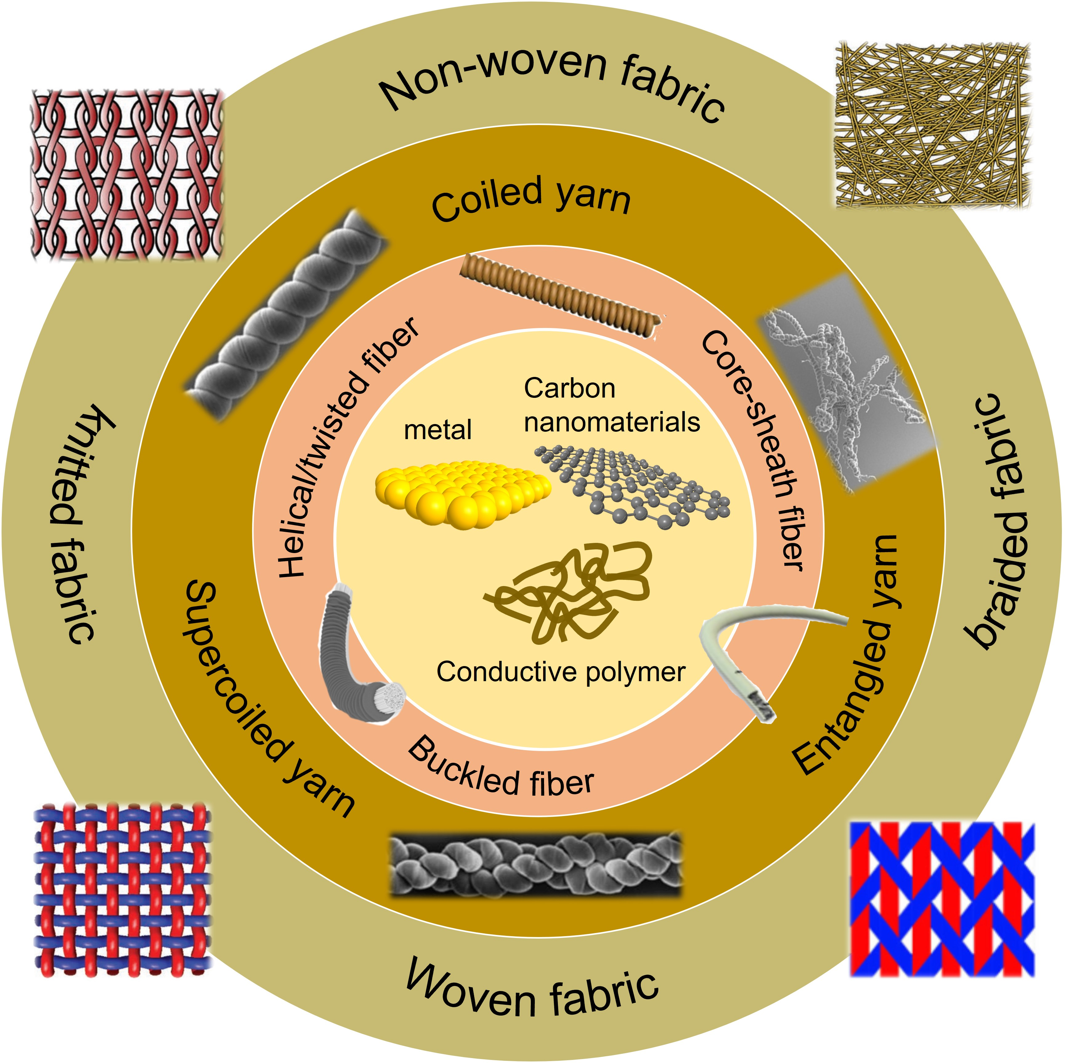
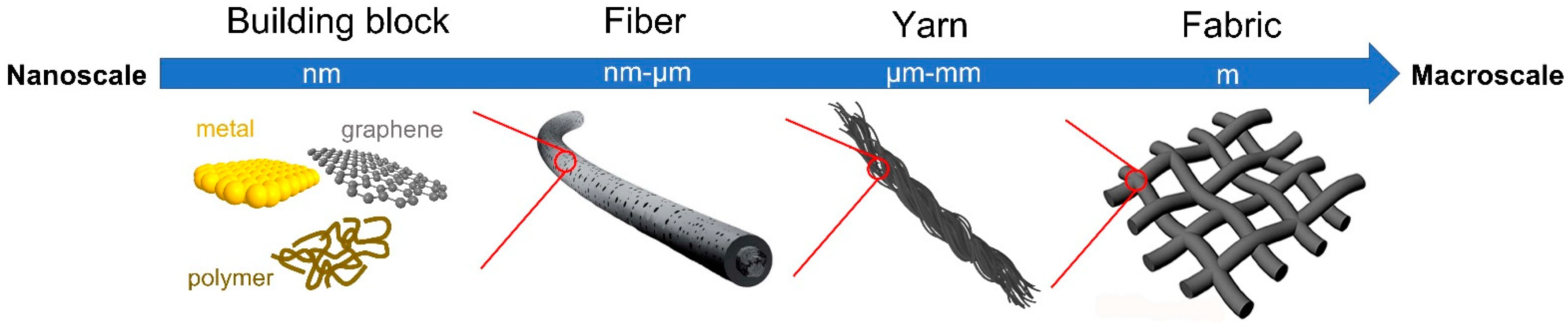
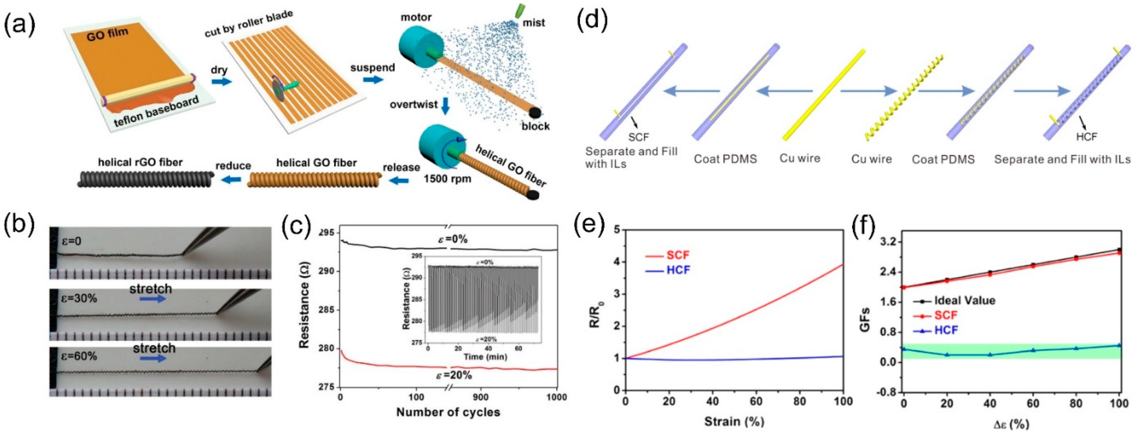
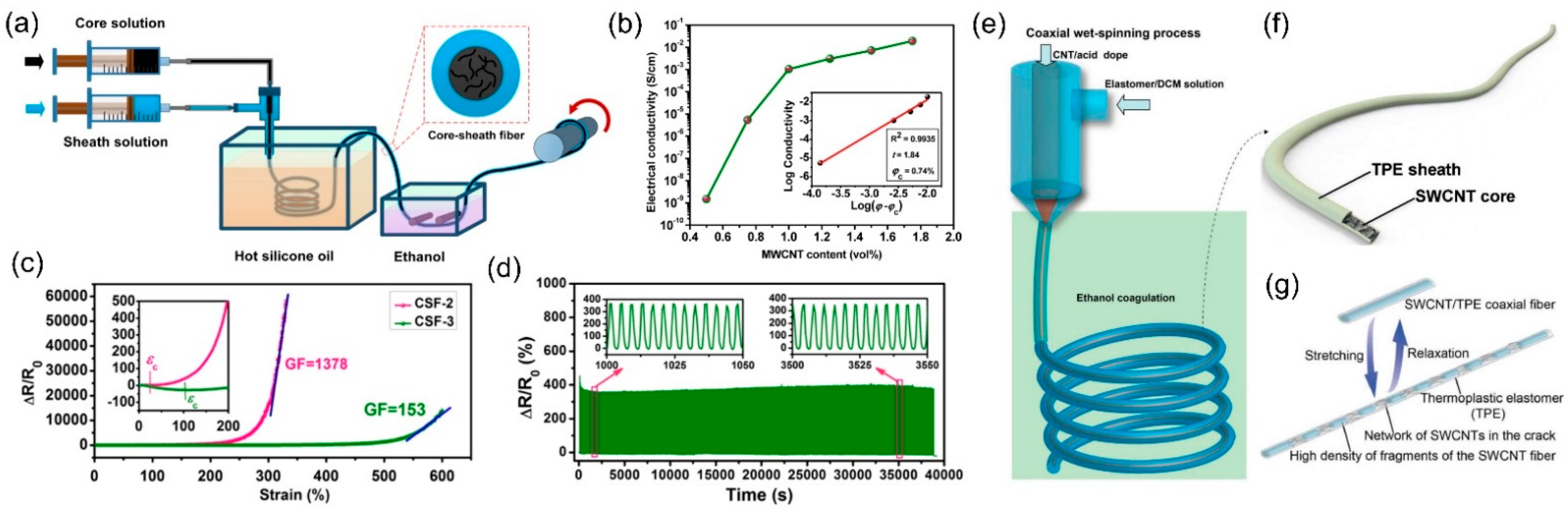
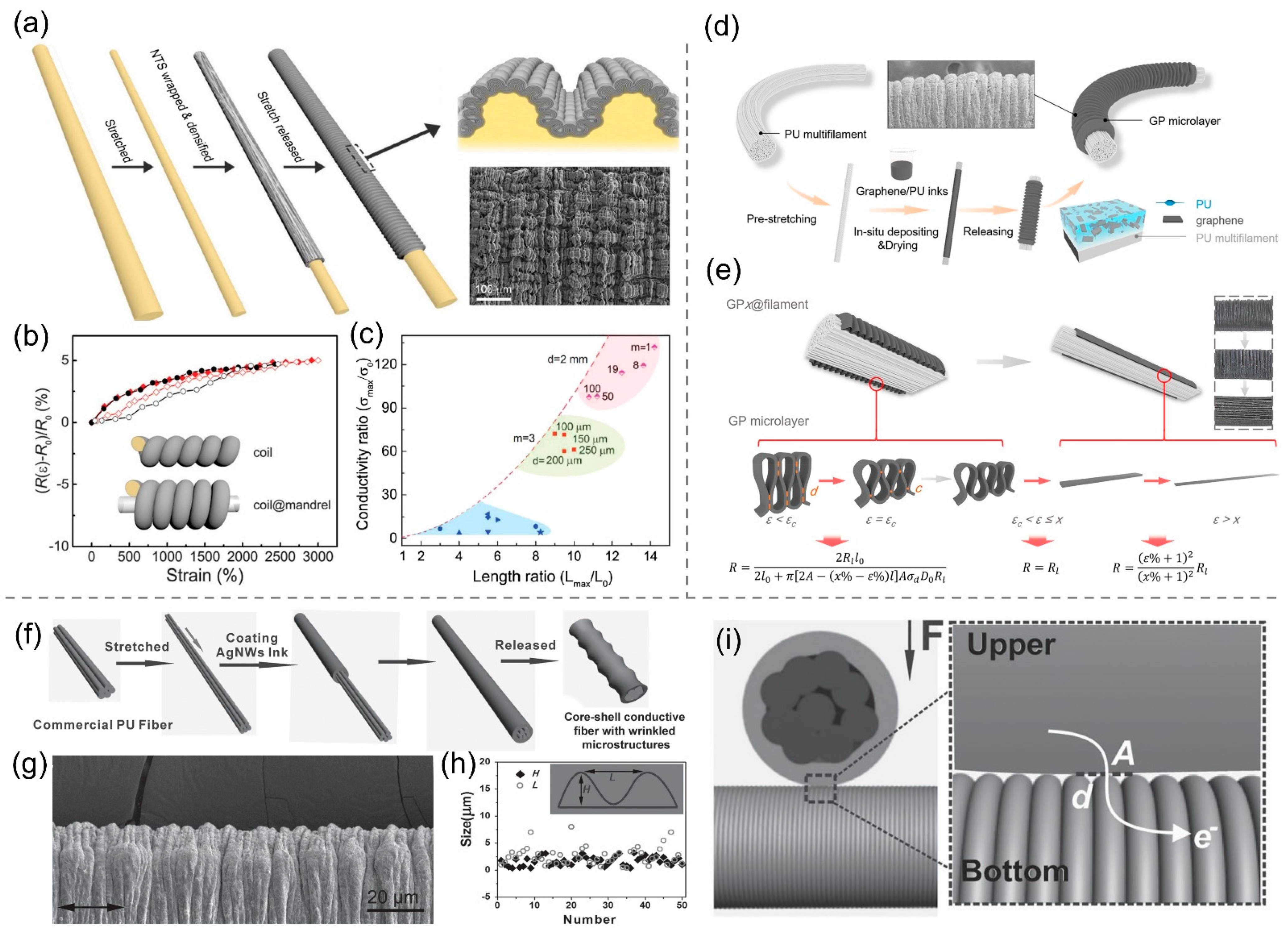
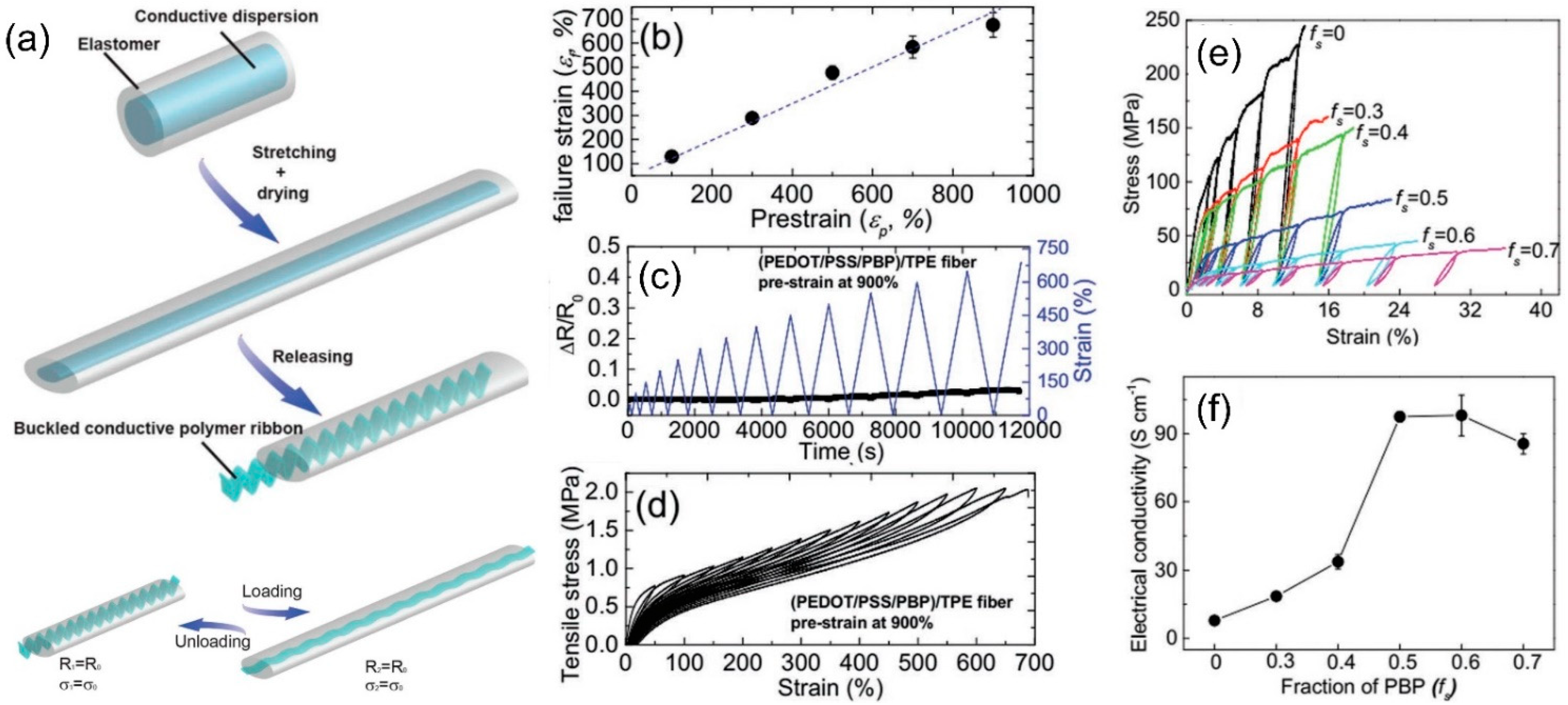
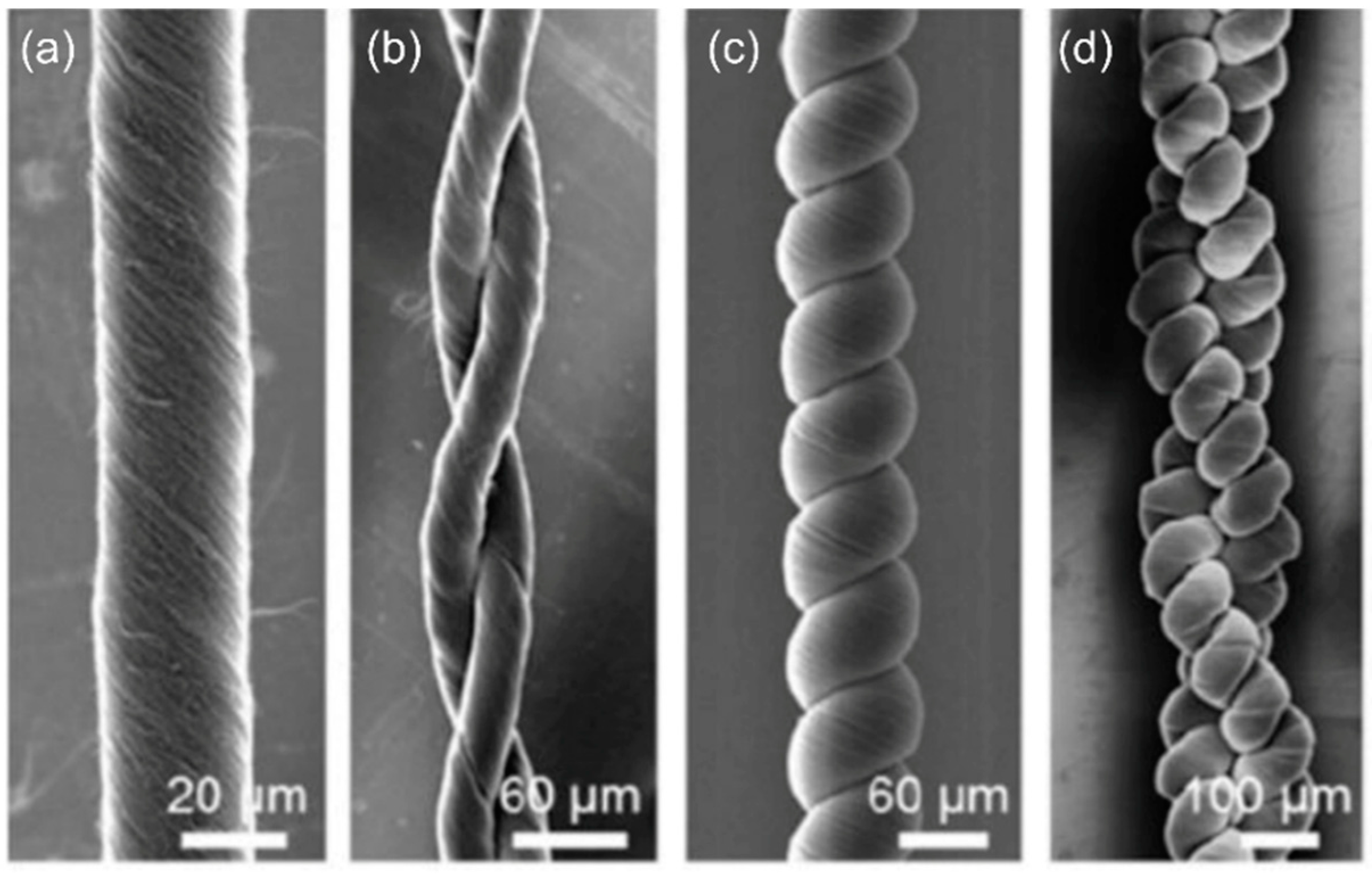
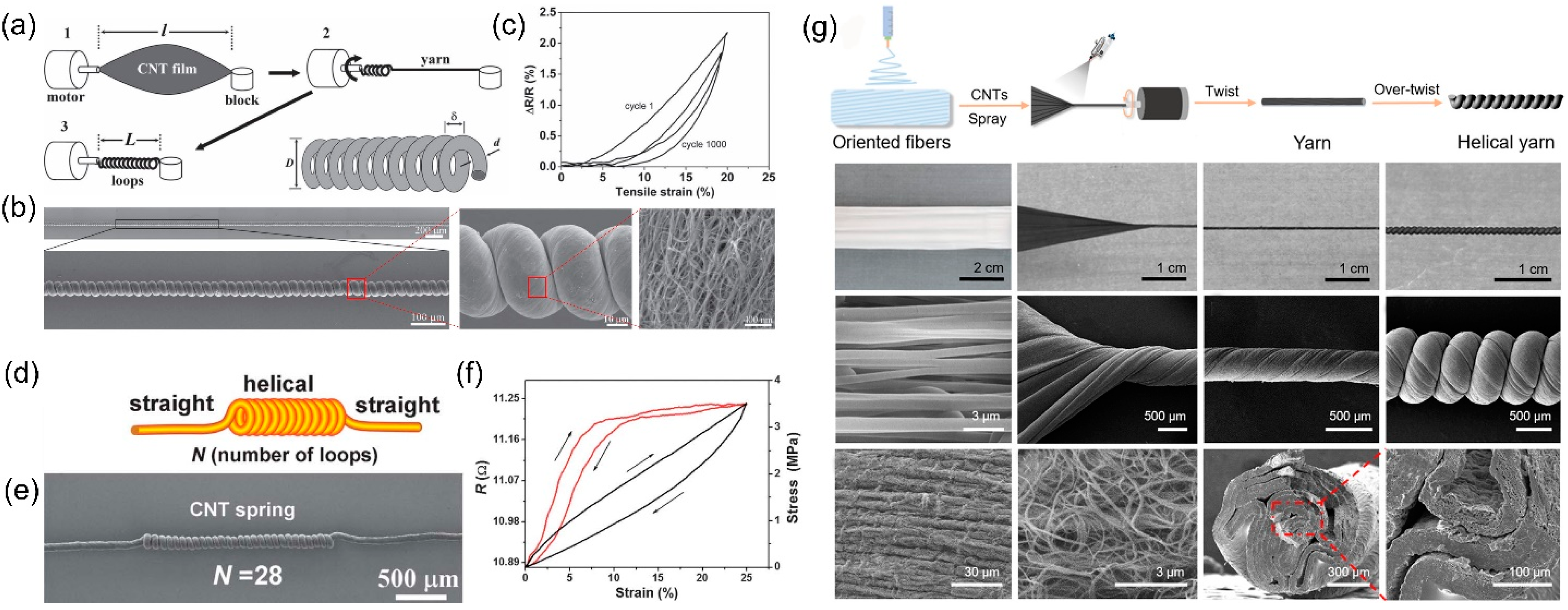
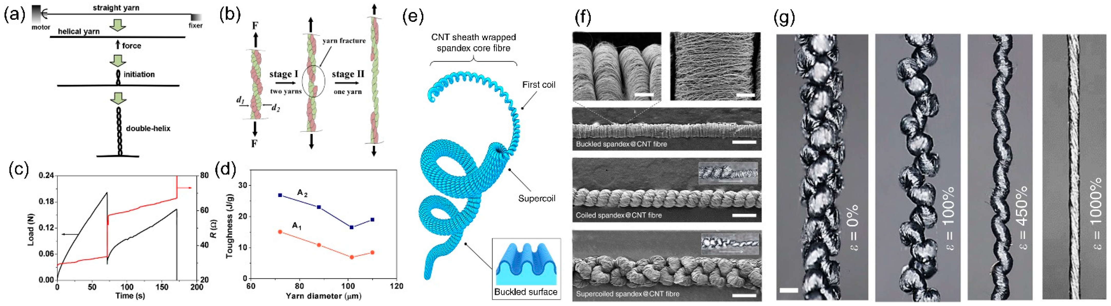
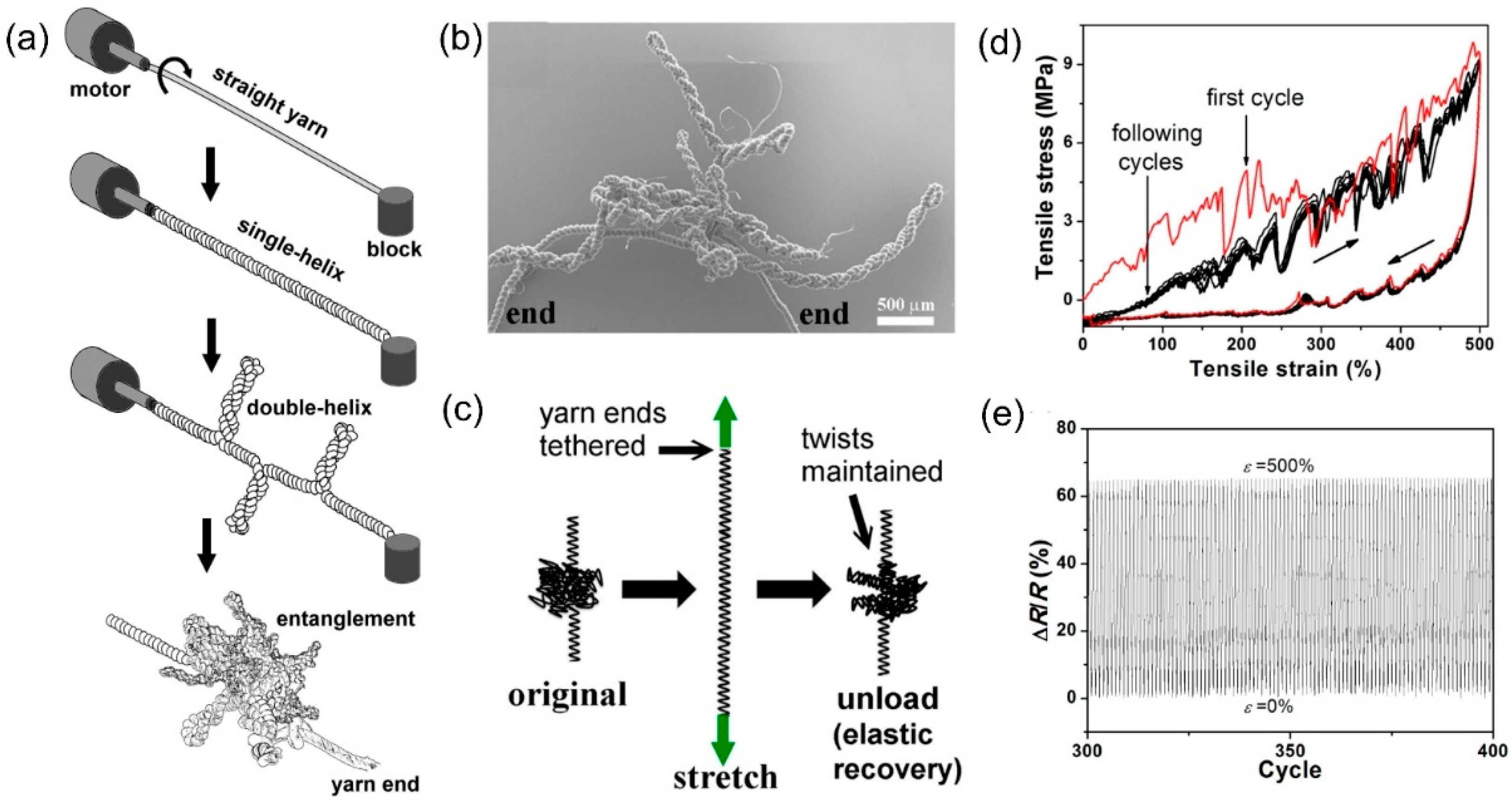
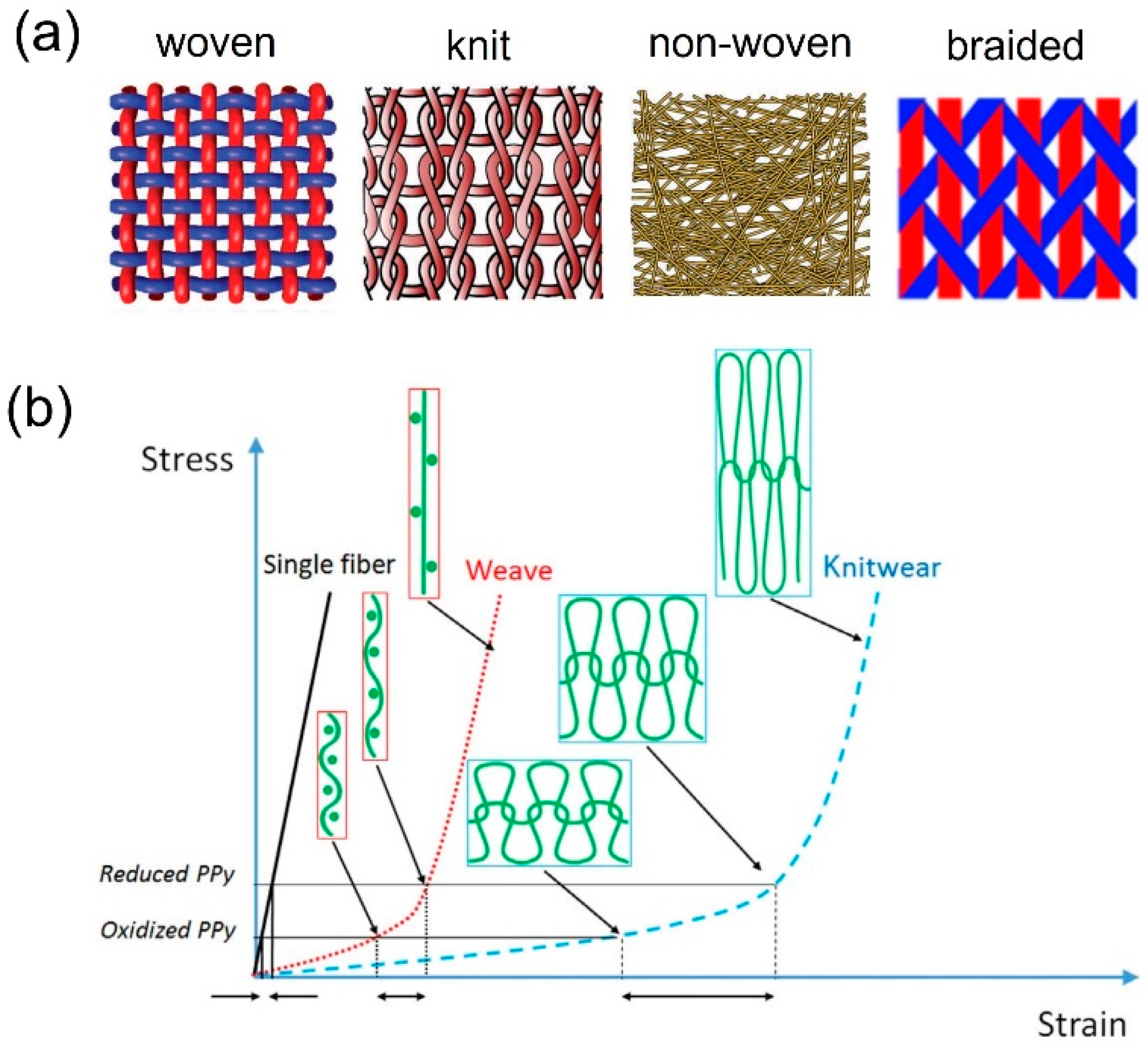
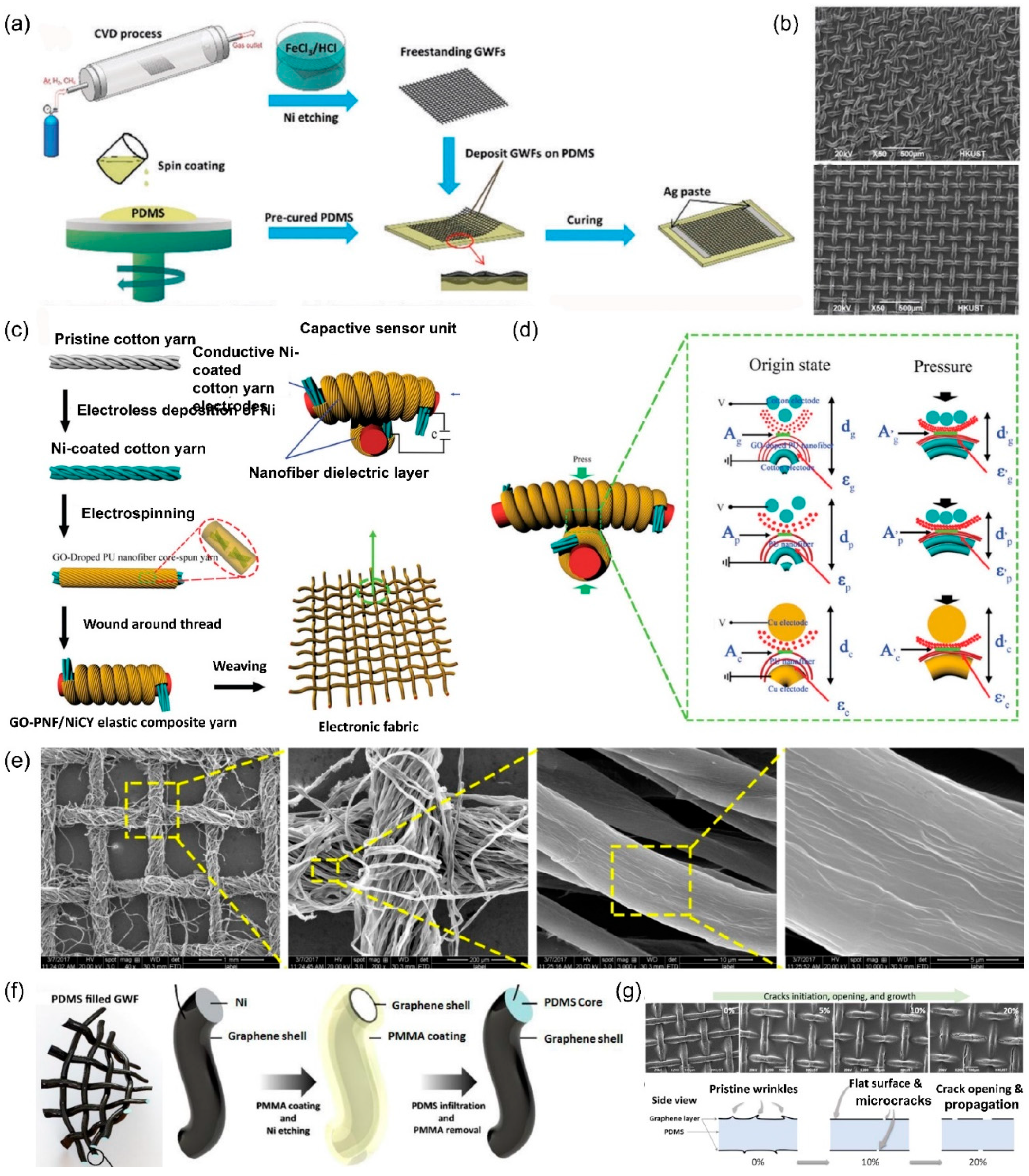
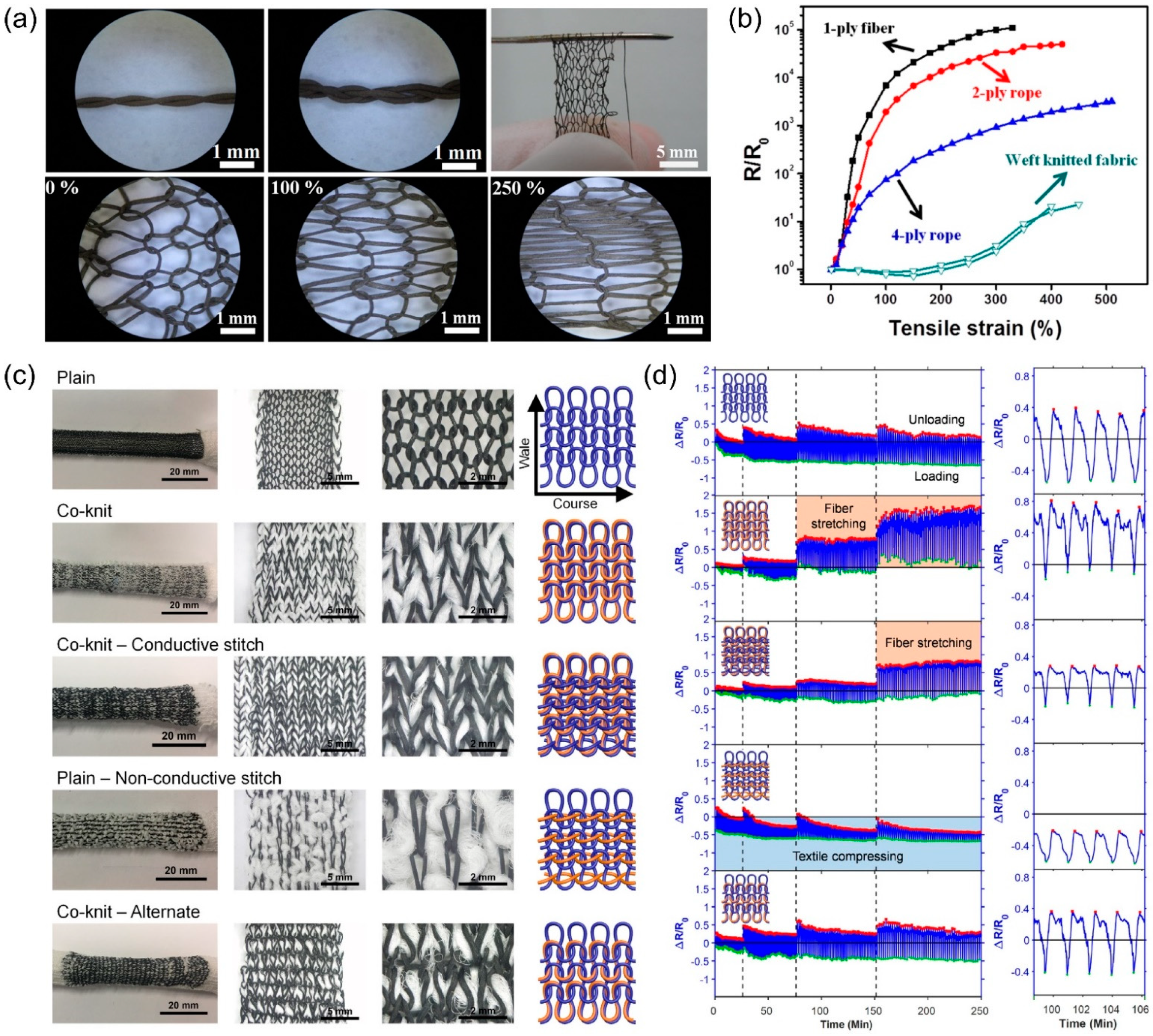
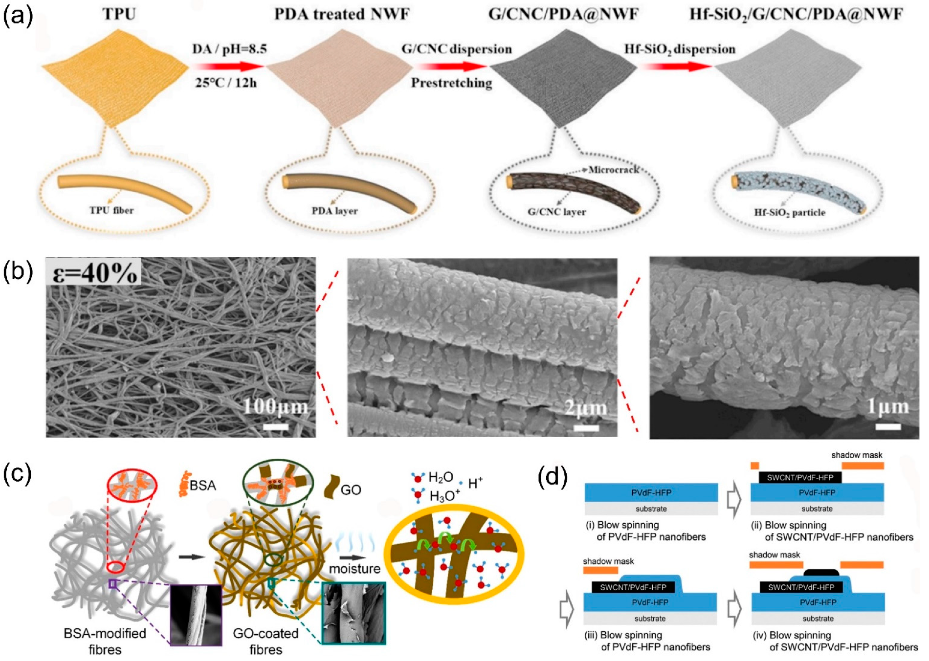
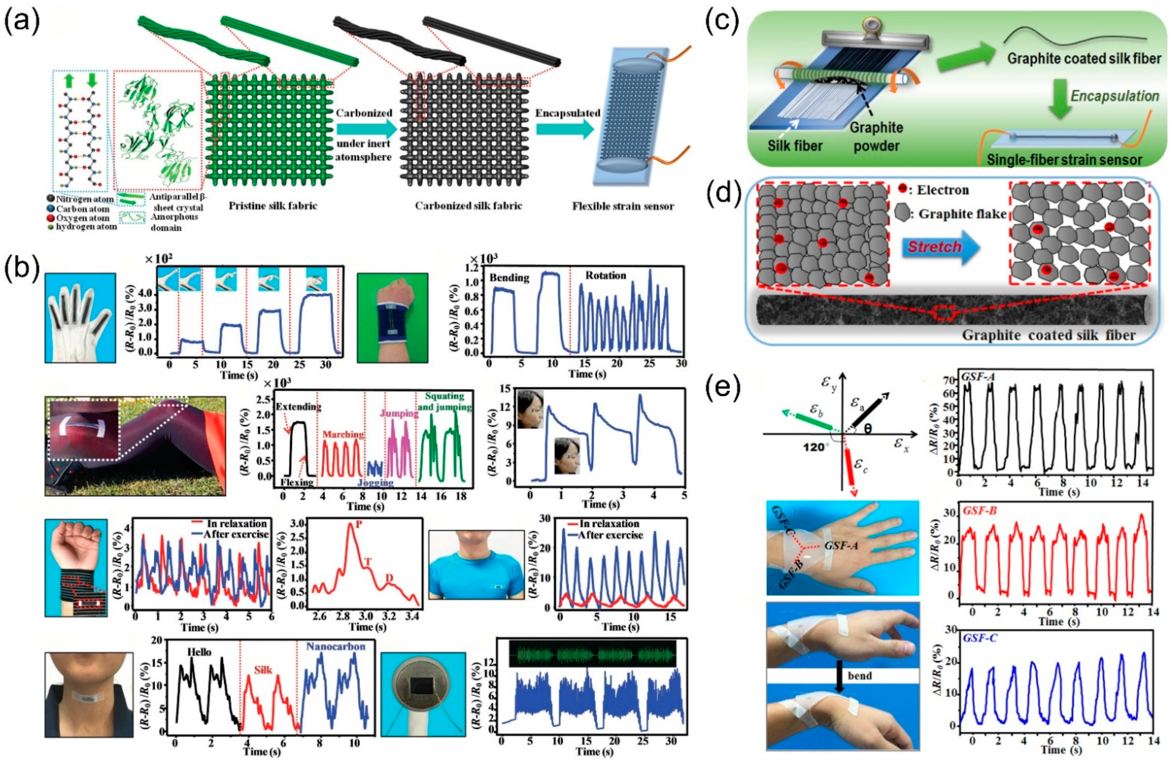
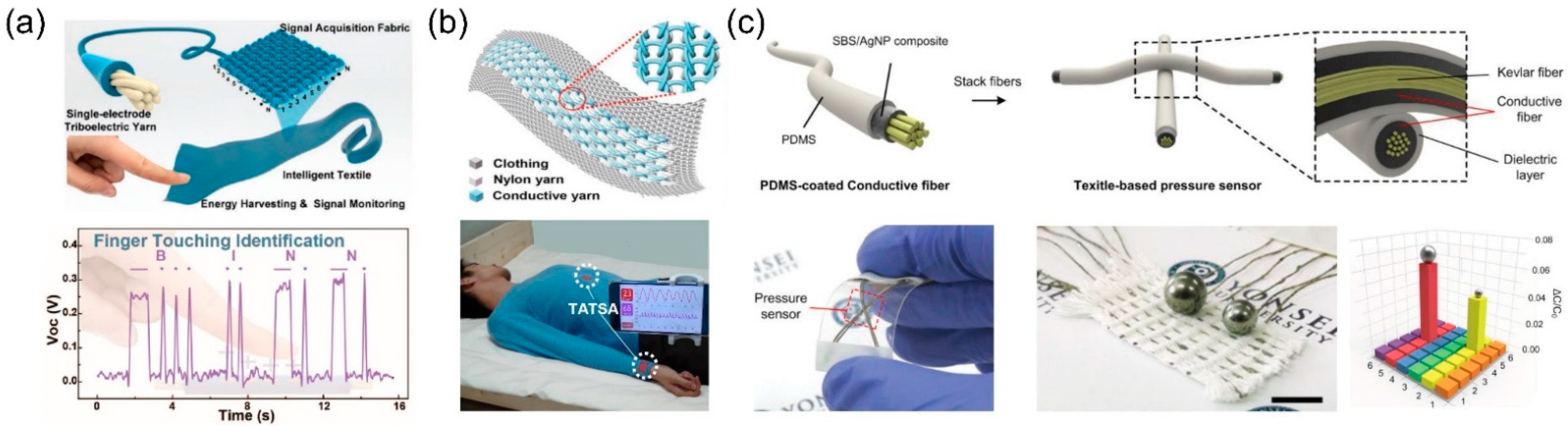
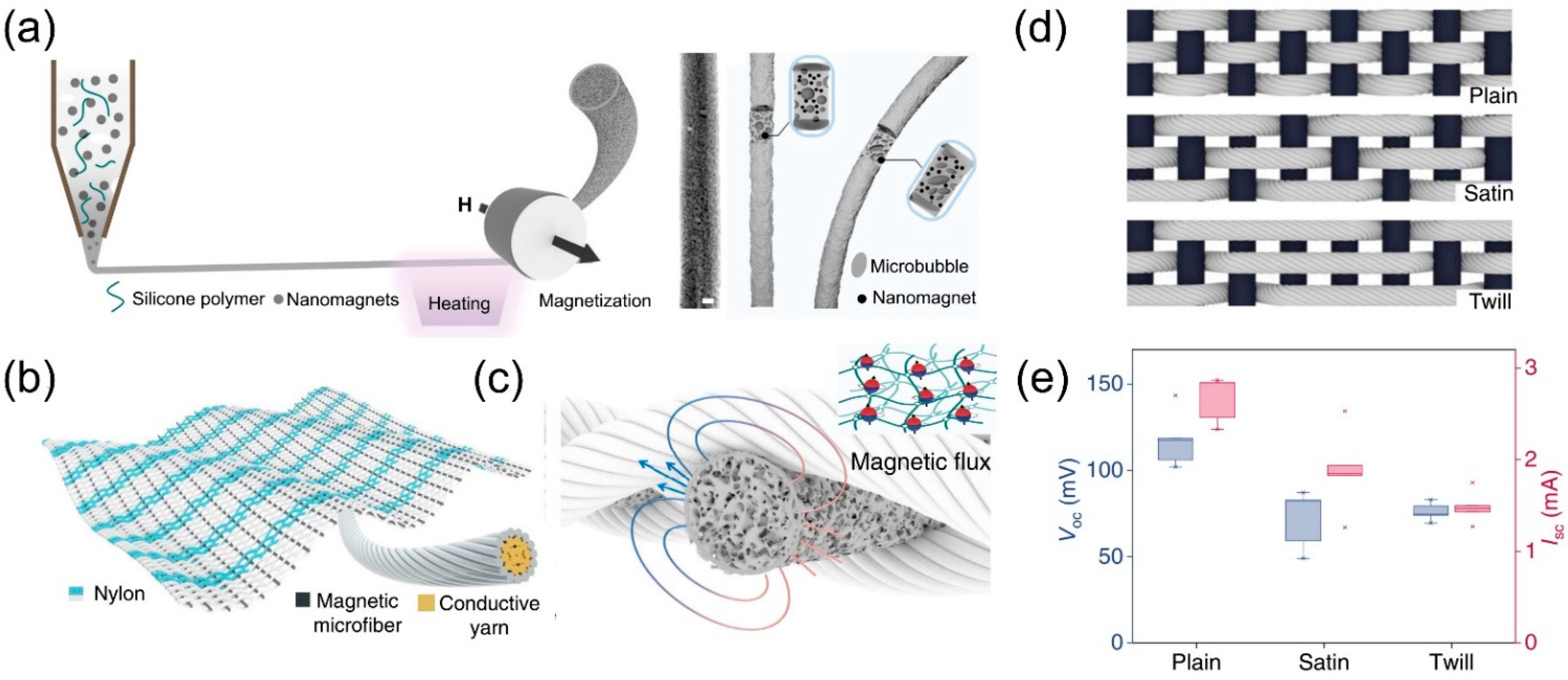
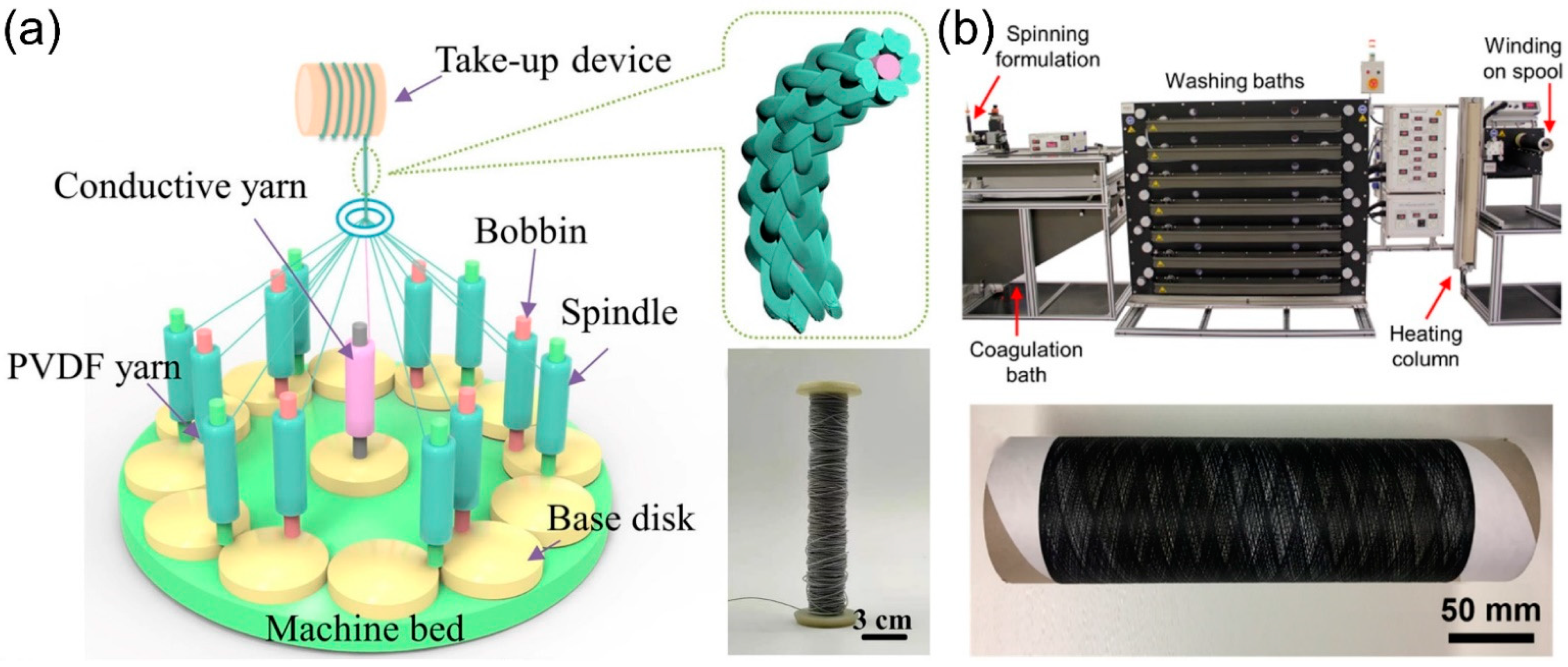
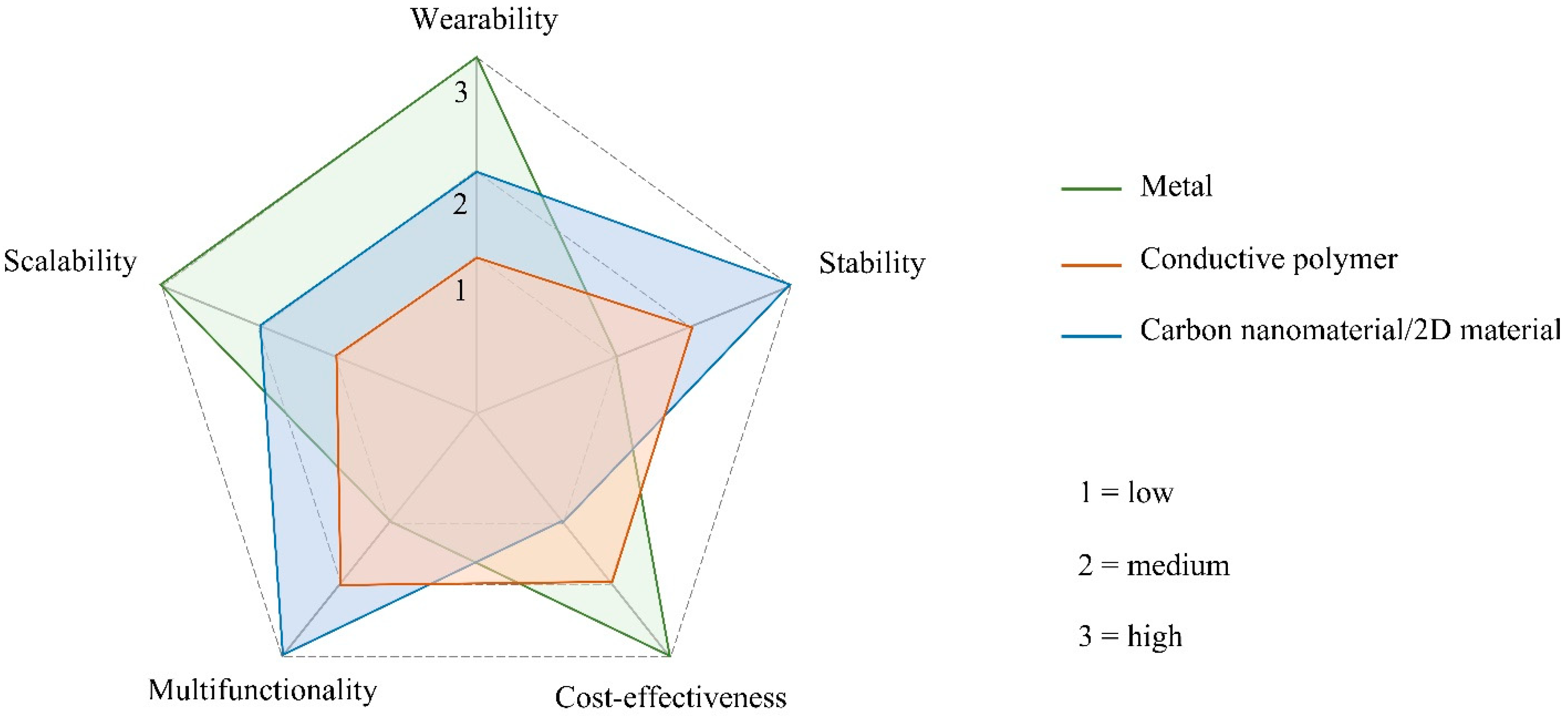
Table 1.
Brief summary of the microstructures and corresponding electrical performance of conductive fibers.
Table 1.
Brief summary of the microstructures and corresponding electrical performance of conductive fibers.
| Materials | Preparation | Strength (MPa) | Electrical Conductivity (S/cm) | Sensing Range (%) | Sensitivity | Response Time (ms) | Cycling Stability | Ref. |
|---|---|---|---|---|---|---|---|---|
| Helical/twisted fiber | ||||||||
| rGO | humidity-assisted strip-scrolling | <10 | 50 | 60 | / | / | 1000 cycles under 20% strain | [62] |
| GO | wet-spinning + twisting-drawing | 130 | / | 29 | / | / | 100 cycles | [63] |
| Ion liquid/PDMS fiber | Template method | 1.0 | 450 | 230 | 0.008 N−1 under 1 N | 80 | 10,000 cycles under 50% strain | [64] |
| Core-sheath fiber | ||||||||
| CNT/PDMS | one-step coaxial wet-spinning | / | ~0.02 | 300 | GF~1378 | <300 | 10,000 cycles | [66] |
| CNT/TPE | coaxial wet-spinning | / | 2804 | 100 | GF~425 | / | 3250 cycles | [67] |
| rGO/ANF | coaxial wet-spinning | 386 | 150 | 18.2 | / | / | / | [68] |
| Carbon grease/PDMS | coaxial extrusion 3D-printing | / | / | / | 0.562 kPa−1 GF~11.8 | 230 | 10,000 cycles | [69] |
| Buckling structured fiber | ||||||||
| Graphene/PU | In situ deposition | 30 | 124 | 815 | / | / | 4000 cycles | [74] |
| silver NWs/PU | Pen brushing | / | 104–105 | 400 | 0.12 kPa−1 | 35 | >4000 cycles | [75] |
| TPE/PBP/PEDOT: PSS | Solution stretching-drying-buckling | / | 95 | 675.8 | / | / | >11,000 cycles | [76] |
Table 2.
Brief summary of the configurations and corresponding sensing performance of conductive yarns.
Table 2.
Brief summary of the configurations and corresponding sensing performance of conductive yarns.
| Materials | Preparation | Strength (MPa) | Electrical Conductivity (S/cm) | Sensing Range (%) | Sensitivity | Cycling Stability | Ref. |
|---|---|---|---|---|---|---|---|
| Coiled yarn | |||||||
| CNT | Spinning of CNT film | 78.3 | 440 | 285 | / | 1000 cycles under 40% strain | [79] |
| CNT | Spinning of CNT film | 76 | / | 25 | GF~0.14 | 1000 cycles | [80] |
| CNT/PU | Twisting | 50.2 | 450 | 1700 | / | 100 cycles under 100% strain | [81] |
| Two-ply coiled and supercoiled yarn | |||||||
| CNT | Spinning + Overtwisting | >50 | / | >150 | 0.08–0.14 Ω/°C | 10,000 cycles | [82] |
| SEBS/CNT/Spandex | Overtwisting + Spray coating | ~80 | Resistance ~65 Ω/cm | 1500 | / | 1000 cycles under 1000% strain | [83] |
| Entangled yarn | |||||||
| CNT | dry-spinning + Spray coating | 100 | Resistance ~200–350 Ω | 500 | / | 600 cycles | [85] |
Table 3.
Brief summary of the fabric patterns and corresponding output performance of textile-based sensors.
Table 3.
Brief summary of the fabric patterns and corresponding output performance of textile-based sensors.
| Materials | Preparation | Electrical Conductivity (S/cm) | Sensing Range | Sensitivity | Response Time (ms) | Cycling Stability | Ref. |
|---|---|---|---|---|---|---|---|
| Weaved fabric | |||||||
| PDMS/Graphene/Ni woven fabric | CVD | 2.73 | GF~223 | / | 1000 cycles | [92] | |
| GO-doped PU/Ni-coated cotton yarns | Electrospinning + helically winding | / | 0–5 N | 1.59 N−1 | <50 | 1000 cycles | [94] |
| rGO/cotton bandage | Dip coating + Pyrolysis | 2.73 | 57% | GF~416 < 40% strain; GF~3667 > 48% strain | <20 | 1000 cycles | [95] |
| PMMA/Graphene/ Ni mesh | CVD + Dip coating | / | 30% | GF~282 at 20% strain | 70 | 4000 cycles | [96] |
| Knitted fabric | |||||||
| silver-coated PA yarns/PU yarn | Electrospinning + twisting + knitting | Resistance ~30–33 Ω | 250% | / | / | 1,000,000 cycles | [98] |
| Ag/CNT/PVDF-HFP | Wet spinning + twisting + knitting | Resistance ~7.8 Ω | 200% | / | / | 3000 cycles | [99] |
| PU/PEDOT:PSS | Wet spinning + knitting | / | 200% | GF~−0.8–0 | / | 500 cycles | [100] |
| Non-woven fabric | |||||||
| Cellulose/Graphene/PDA/TPU | Dip coating | / | 98% | GF~2360 | 33 | 1000 cycles | [101] |
| BSA/GO/NWF | Dip coating | / | / | / | 8900 | 400 s | [102] |
| CNT/PVDF-HFP | Blow spinning | Resistance ~3 kΩ/sq | / | GF~134 | / | 1000 cycles | [103] |
Publisher’s Note: MDPI stays neutral with regard to jurisdictional claims in published maps and institutional affiliations. |
© 2022 by the author. Licensee MDPI, Basel, Switzerland. This article is an open access article distributed under the terms and conditions of the Creative Commons Attribution (CC BY) license (https://creativecommons.org/licenses/by/4.0/).
Share and Cite
MDPI and ACS Style
Wu, S. An Overview of Hierarchical Design of Textile-Based Sensor in Wearable Electronics. Crystals 2022, 12, 555. https://0-doi-org.brum.beds.ac.uk/10.3390/cryst12040555
AMA Style
Wu S. An Overview of Hierarchical Design of Textile-Based Sensor in Wearable Electronics. Crystals. 2022; 12(4):555. https://0-doi-org.brum.beds.ac.uk/10.3390/cryst12040555
Chicago/Turabian StyleWu, Songmei. 2022. "An Overview of Hierarchical Design of Textile-Based Sensor in Wearable Electronics" Crystals 12, no. 4: 555. https://0-doi-org.brum.beds.ac.uk/10.3390/cryst12040555
Note that from the first issue of 2016, this journal uses article numbers instead of page numbers. See further details here.