Article

A Novel Nanostructured Mullite Feedstock for Environmental Barrier Coatings via Atmosphere Plasma Spraying

1
School of Materials Science and Engineering, Harbin Institute of Technology, Harbin 150001, China
2
Liaoning Research Institute of Light Industry, Shenyang 110036, China
3
College of Aerospace Engineering, Shenyang Aerospace University, Shenyang 110136, China
4
Space Environment Simulation Research Infrastructure, Harbin Institute of Technology, Harbin 150001, China
*
Author to whom correspondence should be addressed.
Submission received: 2 March 2022 / Revised: 11 May 2022 / Accepted: 12 May 2022 / Published: 19 May 2022
(This article belongs to the Section Polycrystalline Ceramics)

Abstract

:
A novel strategy is proposed to design an exclusive nanostructured mullite spherical feedstock for environmental barrier coatings (EBCs) via atmosphere plasma spraying (APS). The nanostructured mullite spherical feedstocks are successfully obtained by the procedure of spray drying, solid-phase sintering and flame spheroidization. The crystal grain size of nano-mullite increases with annealing temperature. When the temperature is as high as 1500 °C, the reaction of Al2O3 and SiO2 can be fully completed. The average size is 52 nm for the grain of mullite in feedstocks sintered at 1500 °C, which can be reduced from 52 nm to 48 nm by flame spheroidization treatment as well. Meanwhile, the nanostructured spherical feedstocks show high density and good flowability, which is suitable for APS. The mullite coatings is successfully prepared on a SiC substrate by APS, in which both the nanoscale crystals and nanostructures are perfectly kept as designed. Furthermore, there is no crack appeared in the nanostructured mullite coatings. Thus, the nanostructured mullite feedstock is one of promising candidates for the high performance EBCs.

1. Introduction

Due to their low density and high-temperature stability, silicon-based ceramic materials are excellent candidate materials for hot components of next-generation aviation engines and gas turbines [1,2,3,4]. In the dry oxygen atmosphere, a protective SiO2 layer is formed on the surface of silicon-based ceramics, which is the reason for its excellent oxidation resistance. However, SiO2 layer reacts with vapor water to form volatile Si(OH)4, resulting in corrosion failure of such silicon-based ceramics. In addition, calcia-magnesia-alumino-silicate (CMAS) corrosion is another urgent problem that needs to be solved when silicon-based ceramics are used as aviation engine components [5,6,7]. These two disadvantages have limited the application of silicon-based ceramics in next-generation aviation engines and gas turbines. Environmental barrier coatings (EBCs) have been proposed to improve the corrosion resistance of ceramic components [1,8].
At present, many material systems have been developed for EBCs [9,10]. The current third generation of the EBC system is composed of a silicon bond coat, an intermediate diffusion barrier layer of mullite (Al6Si2O13), and a top layer of rare earth silicates (RE2Si2O7 or RE2SiO5) [11,12,13]. Among them, the mullite layer plays a crucial role in mitigating thermal mismatch and antioxidant activity. Mullite is very attractive due to its high melting temperature (1828 ± 10 °C), high refractoriness, and close thermal expansion coefficient to silicon-based ceramics [14,15,16,17,18]. Atmospheric plasma spraying (APS) is one of the most widely used methods for preparing the EBCs. The studies have found that the cracks, pores and splats are the inherent characteristics of plasma-sprayed coatings [7,15,19,20,21]. The fine cracks and pores can play a role of channels for releasing stress. However, the water vapor and CMAS can penetrate into the mullite interlayer through the vertical cracks and pores, thereby causing an accelerated oxidation and corrosion at the interface between Si bond coat and mullite. The severe oxidation and corrosion will result in the spalling and failure of the EBCs, which is detrimental to the service life and reliability of the aero-engine. Therefore, it is critical to control the number of defects in the plasma sprayed coating.
In order to solve these problems, different methods have been attempted in recent years. One is to adjust the thermal spraying parameters. S. Latzel et al. [20] prepared mullite coating by APS. The results shown that the porosity can be reduced by reducing the spraying distance, increasing the carrier gas flow or changing the gas flow. However, the reduction of these spraying parameters induced the formation of a cracked layer usually. The research indicated the effect of improve the quality of the coatings only by adjusting the plasma spraying parameters is limited. The grain size, density and flowability of the feedstocks are another important factor affecting the quality of the coatings [22,23]. Many studies have found that the properties of coating prepared by nanostructured feedstocks are better than that of microstructured feedstocks [8,21,24]. The nanostructured coatings can reduce the thermal conductivity and cracks in the coatings, which is beneficial to improve the adhesive strength, corrosion resistance, thermal shock resistance, etc. [25,26,27,28]. The coatings prepared by nanostructured feedstocks maintain the characteristics of nano structure, which has high sintering resistance, fracture toughness and wear resistance [29,30]. It is a challenging problem to ensure that coatings prepared by nanostructured feedstocks maintain their nanostructure, which mainly depends on the design, regulation and preparation of feedstock.
However, a shortcoming of nanoparticle powders is that they cannot be successfully thermal sprayed due to their low mass and their inability to be carried in a moving gas stream and deposited onto a substrate. Additionally, the strong surface interaction of individual nanoparticles can lead to agglomeration in the process of powder feeding. Nanoparticle regranulation technology is one of effective methods to prepare the nanostructured feedstocks for plasma spraying [31,32]. Nanoparticle regranulation technology includes spray drying, sintering and even flame spheroidization. For the synthesis of nanostructured mullite feedstock, sintering is the heat treatment of the mixture of Al2O3 and SiO2 nanopowders, which is the key process in regranulation. Flame spheroidization can further improve the density and flowability of the feedstocks. At present, the commercial mullite feedstocks formed by Al2O3 and SiO2 powders are micron-sized. It is an urgent issue to develop nanostructured mullite feedstocks and ensure nanostructured characteristics of the coatings. However, there is no research report on the preparation and characterization of nanostructured mullite feedstocks for plasma spraying.
In this work, nanostructured mullite feedstocks were prepared by nanoparticle regranulation technology. The effect of sintering temperature on the content and grain size of mullite were investigated. The microstructure and phase composition of powders in different preparation stages were analyzed. The flowability, bulk density and tap density of nanostructured mullite feedstocks were tested. The microstructure and phase composition of coating prepared by nanostructured mullite feedstocks were also studied. This work is important to promote the practical application of EBCs in aviation engines and gas turbines.

2. Experimental

2.1. Materials

Nanostructured mullite feedstocks were prepared by using 71.83 wt.% Al2O3 (99.95%, 20 nm, Shanghai Kaiyin Chemical Co., Ltd., Shanghai, China), and 28.17 wt.% SiO2 (99.95%, 20 nm, Ningbo Jinlei Nano Material Technology Co., Ltd., Ningbo, China) as raw materials. The mixture of Al2O3 and SiO2 was mechanically activated in a planetary mill using distilled water, to which ammonium citrate dispersant (Sinopharm Chemical Reagent Co., Ltd., Shanghai, China) and polyvinyl alcohol (Sinopharm Chemical Reagent Co., Ltd., Shanghai, China) were added. After milling, the mixture slurry was spray dried with a rotary atomizer spray dryer equipment LZG-15 (Wuxi Fenghua Drying Equipment Co., Ltd., Wuxi, China). The EBC coating was prepared with Si (20–50 µm, fused and crushed, 99.9% pure, Beijing Dadi Zelin Silicon Industry Co., Ltd., Beijing, China), and mullite feedstocks by APS.

2.2. Process

The mullite water suspension mixture with a 28.5 wt.% of solid content was prepared. To condition the suspensions, 1 wt.% of ammonium citrate dispersant and 0.2 wt.% of PVA binder were added. Thorough mixing of all ingredients was assured by using a planetary mill to avoid powder agglomeration.
The slurries were spray-dried with a rotary atomizer spray dryer equipment. The temperatures at inlet spray dryer change from 190 to 210 °C, while the ranged is from 80 to 100 °C at exit. The slurry was fed at 166 mL/min and 5 × 10⁵ Pa of air pressure. The spray dried powders were sintered in the furnace (HT 64/17, Nabertherm GmbH, Germany) at 1200 °C, 1300 °C, 1400 °C and 1500 °C, respectively. For the flame spheroidization method, the sintered powders were sprayed into a water-filled metal container using an oxygen-acetylene gun (Metco 9M, Oerlikon Metco, Switzerland) at the stand-off distance of 40 cm. The parameters were shown in Table 1. Then, the water was evaporated at 100 °C; and the powder was sieved by 150 mesh.
The mullite/Si coating was thermal sprayed with an APS torch (Metco 9M) onto the SiC substrates, and the parameters are shown in Table 2.

2.3. Characterization Methods

The microstructures of different particles were detected by the scanning electron microscopy (SEM; SS-550 Shimadzu, Kyoto, Japan) equipped with an energy-dispersive X-ray spectroscopy (EDS), and the transmission electron microscopy (TEM; JEOL 2100, Tokyo, Japan).
The bulk density, tap density and repose angle of the particle were determined by a densimeter (BT-1000, Dandong, China). The total time for 50 g powders to fully flow out of the container is the flowability of the powders.
Particle size distributions of spray-dried and sintering powders were determined with a laser diffraction analyzer (Easysizer 2.0, OMEC, Zhuhai, China).
The TG-DTA was performed with Simultaneous Thermal Analyzer of Netzh, model STA 449 F3 (Bayern, Germany), at a heating rate of 10 °C/min, using alumina standard.
Phase analysis was performed using an X-ray diffractometer (XRD-6000, Shimadzu, Tokyo, Japan) with a θ/2θ configuration, in the 2θ range of 10–90°, with 0.0165° steps.
The total porosity (%) of different layers of EBCs was determined by microstructure image processing (MIP) software.

3. Results and Discussion

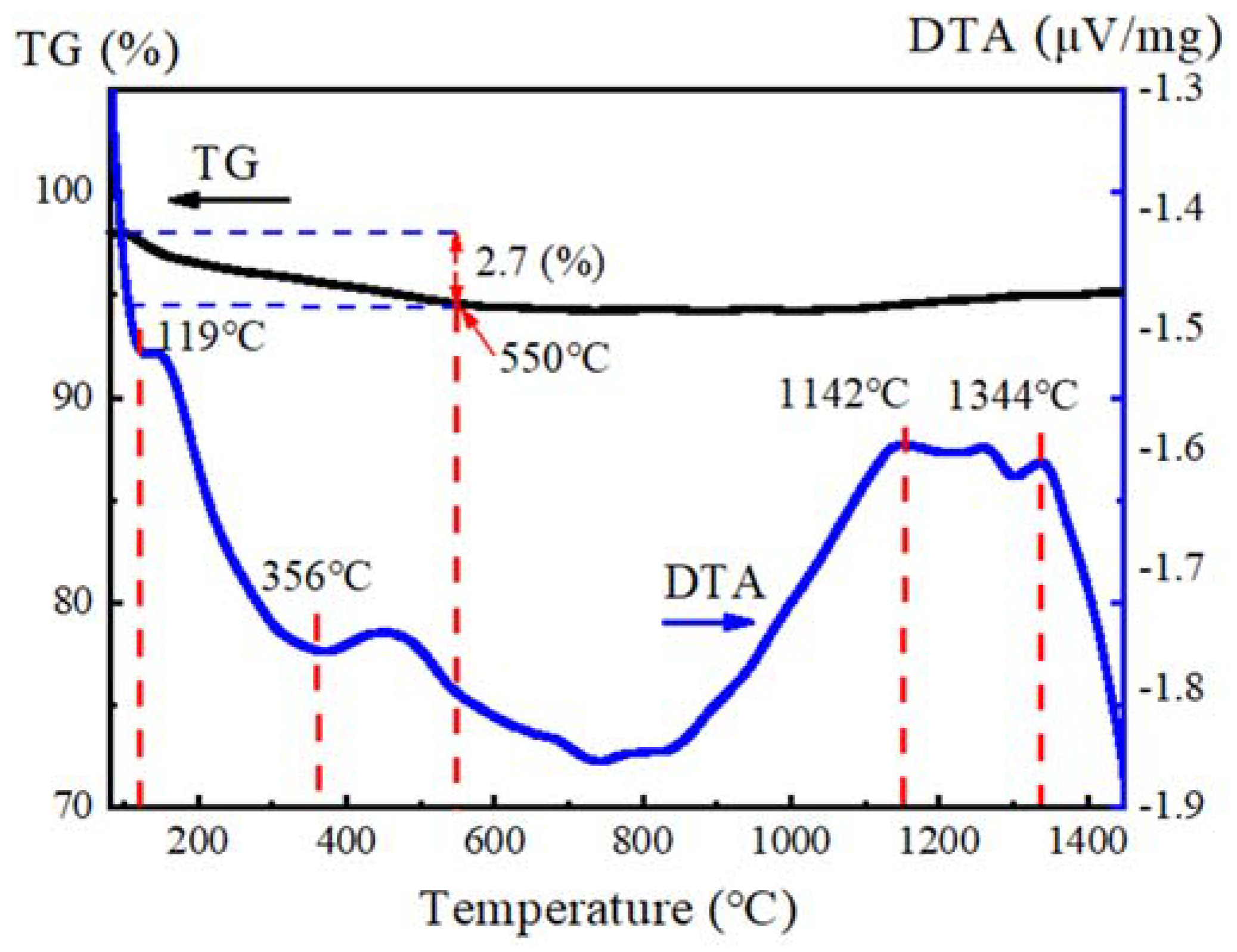
3.1. Characteristic of Spray-Dried Powders

Figure 1 shows the morphology of spray-dried powders. It can be seen that the granulating powders have good sphericity and smooth surface. They displayed typical characteristics of spray granulation powders.
Due to the fine grain size and large specific surface area, the sintering activity of nanostructured powders was higher than that of traditional micrometer powders. In this study, thermal gravity-differential thermal analysis (TG−DTA) of the powders after spray drying was used to determine the reaction temperature, as can be seen in Figure 2. As can be seen from the TG curve, there was about 2.7% mass loss from room temperature (RT) to 550 °C, which is due to the evaporation of water and the decomposition of PVA. The absorption peaks at 119 °C and 356 °C in DTA curve represented the evaporation of water and the decomposition of PVA. No obvious mass change happened in the range of 500–1400 °C. The DTA curve shows an apparent exothermic phenomenon corresponds to the peaks at 1142 °C and 1344 °C, respectively. The exothermic peak of 1142 °C corresponds to the starting reaction temperature [33,34]. The exothermic peak of 1344 °C indicated the violent reaction of Al2O3 and SiO2. The synthesis temperature of mullite was around 1344 °C.
As can be seen in Figure 3, the peaks of mullite, Al2O3 and SiO2 can be detected at 1200 °C, showing that the reaction of the Al2O3 and SiO2 is not enough. The content of mullite increased significantly with the increase of the temperature. When the temperature reached 1500 °C, no amorphous and secondary phases were observed. This indicated the reaction of the Al2O3 and SiO2 was fully completed. A typical mullite structure was observed, and the structure of the powders was in agreement with the results reported by E. Garcia et al. [14].
The synthesized temperature of nanostructured mullite is lower than the Al2O3-SiO2 eutectic temperature (~1590 °C) [35]. The mullitization temperature for the solid-state reaction between Al2O3 and SiO2 can be higher than 1650 °C [36], though some chemical synthetic methods can be used to prepare reactive mullite powders, the reaction temperature of mullite ceramics was higher than 1600 °C [33]. The nanostructured mullite prepared by nanoparticle regranulation technology has effectively reduced the solid-phase sintering temperature.
The distribution of particle size for the powders at different sintering temperatures was shown in Figure 4. As the sintering temperature increased, the distribution range of the particle size for the spray granulated powder became narrowed. There was almost no change after 1300 °C, which indicated the sintering reaction was sufficient at 1300 °C. This result was consistent with the TG-DTA and XRD analysis. The D50 of granulated powders sintered at 1300–1500 °C were approximate 60 µm.
The density and flowability of powders at different sintering temperatures were shown in Table 3. The density and flowability of powders increased with the increase of temperature. The bulk density of powders increased from 0.81 g/cm3 to 1.07 g/cm3 while the tap density increased from 1.03 g/cm3 to 1.26 g/cm3. The repose angle reduced from 32° to 30°. The flowability increased from 222.2 s/50 g to 123.5 s/50 g. With the processing of sintering reaction, the growth of grain resulted in the decrease of voids between different particles. As a result, the particles became dense, thereby facilitating the flow of powders. Properly increasing sintering temperature was beneficial to improve the properties of feedstocks. However, sintering temperature should not be too high to avoid abnormal grain growth in order to obtain nanostructured feedstocks.
Nanostructured powders are the basis of preparation of high-performance ceramic coatings. To confirm that the sintered powders were nanostructured, the average grain sizes of sintered mullite powders were determined by their XRD patterns and the Scherrer equation [37,38]. As can be seen in Table 4, the grain sizes at different sintering temperatures were in nano-scale. The grain size was 52 nm at 1500 °C. The comprehensive properties of coatings depend on the composition, microstructure, density and flowability of feedstocks. The mullite powders sintered at 1500 °C have nanostructure and the best flowability. Therefore, it is suitable for preparation of nanostructured EBCs by plasma spraying.

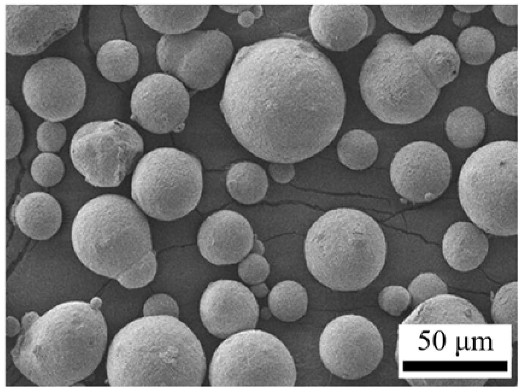
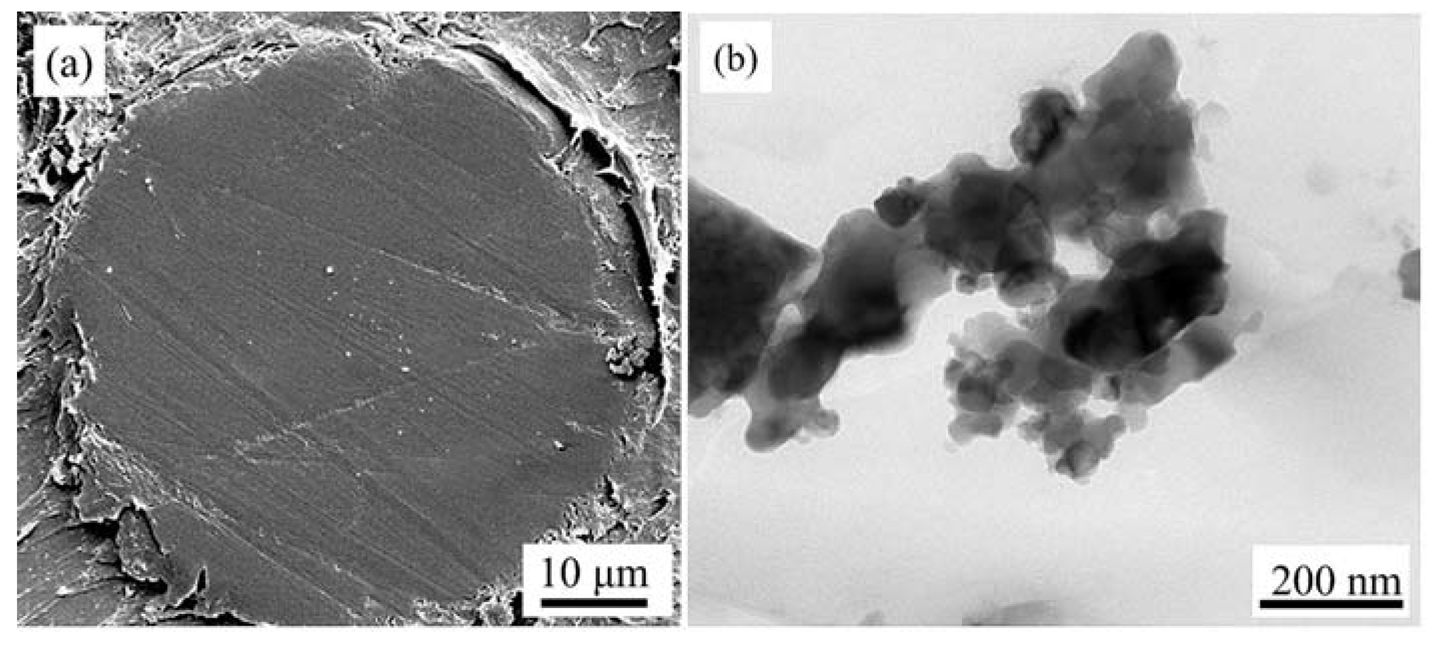
3.2. Characterization of Flame Spheroidized Powders

In order to facilitate thermal spraying, flame spheroidization process was used to further enhance the flowability and density of the powder. A proportion of the granules were sintered at 1500 °C for 2 h before the flame spheroidization treatment. The microstructure and cross-section morphology were shown in Figure 5 and Figure 6. The micrographs of flame spheroidization mullite powders show the granule surfaces appeared smooth and dense. In the flame spheroidization process, the powder melted into liquid droplets under the plasma heat source. Under the protection of argon atmosphere, the small liquid droplets cooled rapidly and solidified into a spherical powder due to surface tension. This flame spheroidization process improved the density of the powders significantly. It indicated sphericity of the granules was improved after flame spheroidization treatment. The EDS analysis (Figure 5b) indicated that the elements of Al, Si and O were uniformly distributed on the surface of the particles. The energy spectrum element analysis of the powder was shown in Figure 5b. It can be seen that the content of Al, Si, O elements was equivalent to the stoichiometric (3Al2O3·2SiO2) composition of mullite.
Figure 6a displays the cross-section morphology of a particle of the mullite powder. No hole was observed in the polished cross-section and the structure was dense. In order to investigate the grain size of powders after flame spheroidization process, the feedstocks were dispersed before TEM analysis. The results of TEM analysis are shown in Figure 6b. It can be seen in Figure 6b, the grain size of feedstocks after flame spheroidization process was still nanostructured.
Figure 7 presented the XRD patterns of flame spheroidization mullite powders. The sharp and intense peaks on the XRD patterns were characteristic of mullite, which indicated that the powders were fully crystallized by the flame spheroidization method. This is because the process from melting to solidification of powder particles is very short in the flame spheroidization process. The flame spheroidization process is the reconstruction of powder particles without changing the original organization. Therefore, there is no disappearance of old phases and the appearance of new phases.
Two diffraction peaks, at the angle range of 25.5–26.5° in the pattern of flame spheroidization mullite, were in accord with the XRD patterns of JCPDF 79-1456. The two diffraction peaks were indexed on an orthorhombic lattice as (120) and (210). According to the XRD patterns of (210) lattice, the Debye–Scherrer equation was used to calculate the grain size of flame spheroidization mullite powders. The average grain sizes of flame spheroidization mullite powders were approximate 48 nm. The bulk density was 1.21 g/cm3 and flowability was 88.7 s/50 g (Table 5), which is superior to the characteristics of sintering feedstocks. The results indicated that the physical properties of flame spheroidization feedstocks, such as flowability and density, have been greatly improved. In the plasma spraying process, the heat is easily transmitted into the powder due to the high bulk density of the flame spheroidization mullite feedstocks. As a result, the flame spheroidization mullite feedstocks will be heated and melted to form a dense coating structure. Therefore, the flame spheroidization treated nanostructured mullite feedstocks are more suitable for plasma spraying to prepare high-quality EBCs.

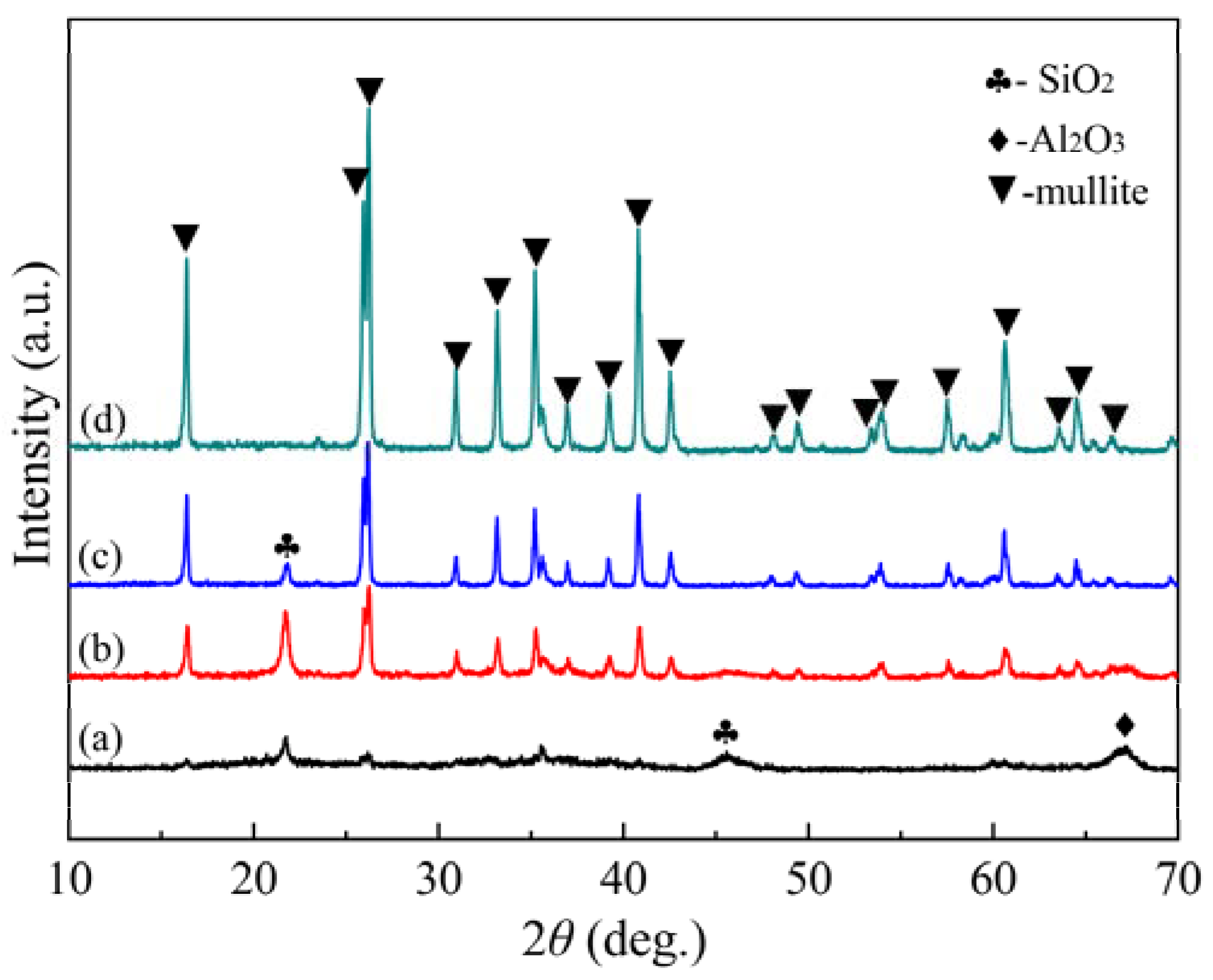
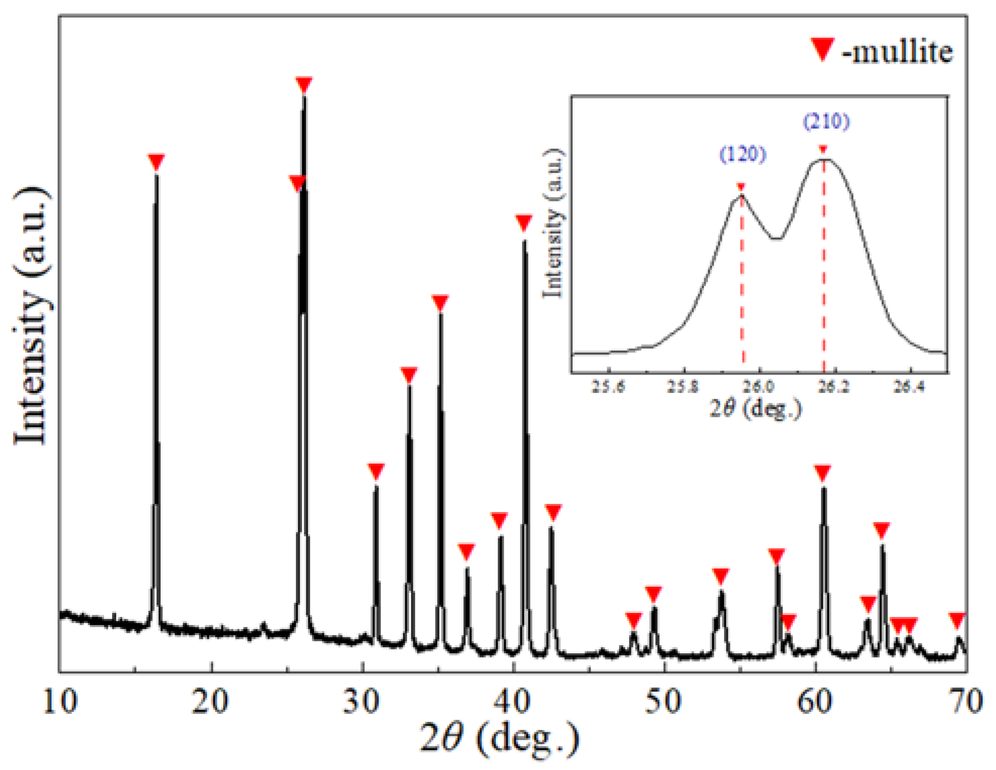
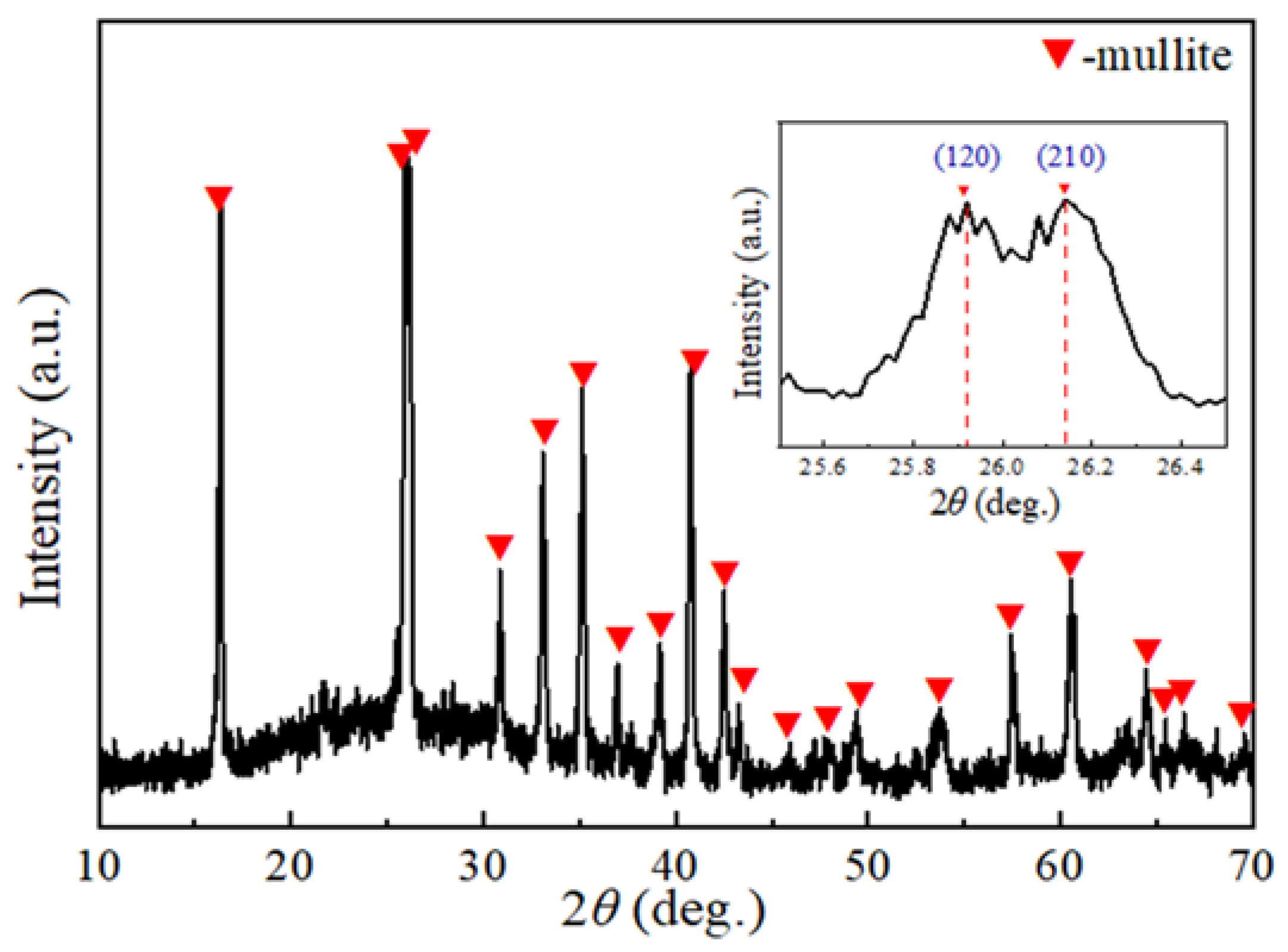
3.3. Phase Composition of Mullite Coating

Nanostructured mullite coating was successfully prepared by plasma spraying with flame spheroidized mullite powders. Figure 8 shows the XRD pattern of as-sprayed mullite coating. As can be seen from the figure, the as-sprayed mullite coating exhibited a high degree of crystallinity, which was beneficial to improve the thermal shock resistance and adhesion of the coating [13]. The average grain size of the mullite coating was 35 nm, which was determined from Figure 8 by using the Scherrer equation. This indicated the mullite coating was nanostructured. The rapid melting and solidification in the plasma spraying process decreased the grain size of the coating.

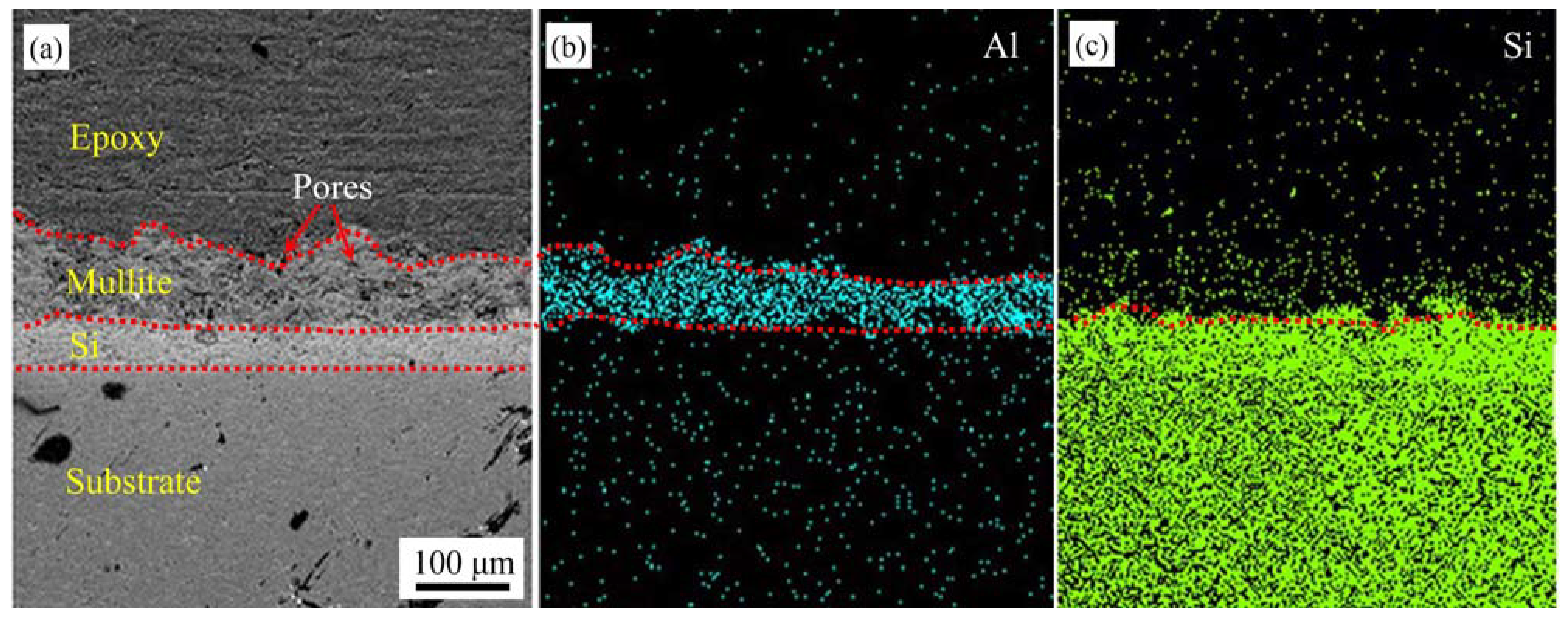
3.4. Morphology of Nanostructured Environmental Barrier Coating

Figure 9 depicted the cross-sectional morphologies of the as-sprayed coating. It showed typical bi-layer coating structure. The top mullite layer was a continuous layer (with 60–80 µm thickness). It can be seen that the mullite/Si coating exhibited good bonding. The different layers can be distinguished by observing the distribution of Al, Si elements in the coating. All elements in the coating were evenly distributed. The Si layer appeared dense and almost no visible pores, which combined with the substrate closely.
No crack was found in the nanostructured mullite coating. This is because the flowability of the feedstocks is good and the distribution of particle size is uniform, which results in the melting of the feedstocks is relatively uniform in the plasma spraying process. Therefore, the residual stress in the coating after the spraying is relatively small. There are some tiny closed pores in the coating, which was caused by the unmelted nanoparticles. The interior structure of the nano zone was beneficial to the corrosion resistance, because the water vapor and CMAS cannot penetrate into the layer. The small closed pores can enhance phonon scattering, reduce thermal diffusivity, relieve the stress of the coating, and improve the toughness and its thermal shock resistance [39,40].
Image-Pro Plus software was used to process the coating cross-section SEM images and calculate their corresponding porosities. Table 6 showed the porosities and cracks of mullite layers prepared by different feedstocks. The porosity of nanostructured mullite coating is 6.5%, which indicated that the coating has high density. The reason for the high density of the nanostructured mullite coating can be attributed to two aspects. On the one hand, the density of the spraying feedstocks after flame spheroidization treatment is very high. No pores were detected on the surface and inside of the mullite powders. On the other hand, the particles impact the underlying Si coating at high speed during the plasma spraying process, resulting in the spherical particles transforming into flat particles. The high flatness of the particles is beneficial to the melting of the nanoparticles by the plasma flame. Therefore, the porosity of the coating is significantly reduced.
Compared with the microstructured mullite layers, nanostructured mullite coating should display superior properties. Consequently, the nanostructured mullite coating has promising prospects in the next generation advanced EBCs.

4. Conclusions

(1) Nanostructured mullite spherical feedstocks were prepared by nanoparticle regranulation technology. The D50 of granulated powders sintered at 1300–1500 °C was approximate 60µm. The grain size was 52 nm at 1500 °C. The bulk density was 1.07 g/cm3 with the flowability of 123.5 s/50 g, which is suitable for plasma spraying.
(2) The sintering temperatures have an obvious influence on the synthesis of nanostructured mullite. The formation of mullite started at 1200 °C. With the increase of the temperature, the diffraction peak of mullite enhanced. The reaction of Al2O3 and SiO2 was fully completed at 1500 °C. The nanostructured mullite prepared by nanoparticle regranulation technology has effectively reduced the solid-phase sintering temperature.
(3) The flame spheroidization reduced the grain size of the nanostructured mullite. After flame spheroidization, the grain size of the spherical feedstocks was 48 nm. The flowability was 88.7 s/50 g and the bulk density was 1.21 g/cm3. The flame spheroidized nanostructured mullite feedstocks are more suitable for plasma spraying to prepare high-quality environmental barrier coatings.
(4) The grain size of mullite coating is 35 nm. The rapid melting and solidification in the plasma spraying process decreased the grain size of the coating. The porosity of nanostructured mullite coating was 6.5% and no crack was found. The high density of the nanostructured mullite coating can be attributed to the high density of the spraying feedstocks after flame spheroidization treatment, and the nanostructured mullite particles impact the underlying Si coating at high speed during plasma spraying process. A small amount of tiny closed pores in the coating were beneficial to the corrosion resistance of the coating. The nanostructured mullite coating has promising prospects in the next generation advanced environmental barrier coatings.

Author Contributions

Conceptualization, X.Z.; methodology, J.J.; validation, X.Z., F.X. and X.G.; investigation, L.W.; resources, M.Y.; data curation, S.L.; writing—original draft preparation, F.X.; writing—review and editing, X.G.; funding acquisition, Y.W. All authors have read and agreed to the published version of the manuscript.

Funding

This research was funded by National Science and Technology Major Project (No. 2017-VI-0020-0093), National Key Research and Development Project (No. 2020YFB2007900), Open Foundation from National Key Laboratory of Materials Behavior and Evaluation Technology in Space Environments, National Natural Science Foundation of China (No. 52001217) and Doctoral Start-up Foundation of Liaoning Province (No. 2021-BS-195).

Institutional Review Board Statement

Not applicable.

Informed Consent Statement

Not applicable.

Data Availability Statement

Not applicable.

Conflicts of Interest

The authors declare no conflict of interest.

References

  1. Lee, K.N. Current Status of Environmental Barrier Coatings for Si-Based Ceramics. Surf. Coat. Technol. 2000, 133–134, 1–7. [Google Scholar] [CrossRef]
  2. Basu, S.N.; Sarin, V.K. Thermal and Environmental Barrier Coatings for Si-Based Ceramics. Compr. Hard Mater. 2014, 2, 469–489. [Google Scholar]
  3. Ramasamy, S.; Tewari, S.N.; Lee, K.N.; Bhatt, R.T.; Fox, D.S. Slurry Based Multilayer Environmental Barrier Coatings for Silicon Carbide and Silicon Nitride Ceramics—I. Processing. Surf. Coat. Technol. 2010, 205, 258–265. [Google Scholar] [CrossRef]
  4. Bhatt, R.T.; Choi, S.R.; Cosgriff, L.M.; Fox, D.S.; Lee, K.N. Impact Resistance of Environmental Barrier Coated SiC/SiC Composites. Mater. Sci. Eng. A 2008, 476, 8–19. [Google Scholar] [CrossRef]
  5. Eaton, H.E.; Linsey, G.D. Accelerated Oxidation of SiC CMC’s by Water Vapor and Protection via Environmental Barrier Coating Approach. J. Eur. Ceram. Soc. 2002, 22, 2741–2747. [Google Scholar] [CrossRef]
  6. Ueno, S.; Ohji, T.; Lin, H.T. Corrosion and Recession of Mullite in Water Vapor Environment. J. Eur. Ceram. Soc. 2008, 28, 431–435. [Google Scholar] [CrossRef]
  7. Stolzenburg, F.; Kenesei, P.; Almer, J.; Lee, K.N.; Johnson, M.T.; Faber, K.T. The Influence of Calcium- Magnesium-Aluminosilicate Deposits on Internal Stresses in Yb2Si2O7 Multilayer Environmental Barrier Coatings. Acta Mater. 2016, 105, 189–198. [Google Scholar] [CrossRef] [Green Version]
  8. Bakan, E.; Marcano, D.; Zhou, D.; Sohn, Y.J.; Mauer, G.; Vaßen, R. Yb2Si2O7 Environmental Barrier Coatings Deposited by Various Thermal Spray Techniques: A Preliminary Comparative Study. J. Therm. Spray Technol. 2017, 26, 1011–1024. [Google Scholar] [CrossRef]
  9. Chen, H.; Zhang, C.; Liu, Y.-C.; Song, P.; Li, W.-X.; Yang, G.; Liu, B. Recent progress in thermal/environmental barrier coatings and their corrosion resistance. Rare Met. 2020, 5, 498–512. [Google Scholar] [CrossRef]
  10. Laura, R.T.; Nitin, P.P. Towards multifunctional thermal environmental barrier coatings (TEBCs) based on rare-earth pyrosilicate solid-solution ceramics. Scripta Mater. 2018, 154, 111–117. [Google Scholar]
  11. Botero, C.A.; Jimenez-Pique, E.; Martin, R.; Kulkarni, T.; Sarin, V.K.; Llanes, L. Influence of Temperature and Hot Corrosion on the Micro-Nanomechanical Behavior of Protective Mullite EBCs. Int. J. Refract. Met. Hard Mater. 2015, 49, 383–391. [Google Scholar] [CrossRef]
  12. Price, J.R.; van Roode, M.; Stala, C. Ceramic Oxide-Coated Silicon Carbide for High Temperature Corrosive Environments. Key Eng. Mater. 1992, 72, 71–84. [Google Scholar] [CrossRef]
  13. Lee, K.N.; Miller, R.A.; Jacobson, N.S. New Generation of Plasma-Sprayed Mullite Coatings on Silicon Carbide. J. Am. Ceram. Soc. 1995, 78, 705–710. [Google Scholar] [CrossRef] [Green Version]
  14. Garcia, E.; Mesquita-Guimaraes, J.; Miranzo, P.; Osendi, M.I.; Wang, Y.; Lima, R.S.; Moreau, C. Mullite and Mullite/ZrO2-7wt.%Y2O3 Powders for Thermal Spraying of Environmental Barrier Coatings. J. Therm. Spray Technol. 2010, 19, 286–293. [Google Scholar] [CrossRef] [Green Version]
  15. Cojocaru, C.V.; Levesque, D.; Moreau, C.; Lima, R.S. Performance of Thermally Sprayed Si/Mullite/BSAS Environmental Barrier Coatings Exposed to Thermal Cycling in Water Vapor Environment. Surf. Coat. Technol. 2013, 216, 215–223. [Google Scholar] [CrossRef]
  16. Garcia, E.; Mesquita-Guimaraes, J.; Miranzo, P.; Osendi, M.I. Crystallization Studies in Mullite and Mullite-YSZ Beads. J. Eur. Ceram. Soc. 2010, 30, 2003–2008. [Google Scholar] [CrossRef]
  17. Mah, T.I.; Mazdiyasni, K.S. Mechanical Properties of Mullite. J. Am. Ceram. Soc. 2010, 66, 699–703. [Google Scholar] [CrossRef]
  18. Hamidouche, M.; Bouaouadja, N.; Olagnon, C.; Fantozzi, G. Thermal shock behaviour of mullite ceramic. Ceram. Int. 2003, 29, 599–609. [Google Scholar] [CrossRef]
  19. Lee, K.N.; Miller, R.A. Development and Environmental Durability of Mullite and Mullite/YSZ Dual Layer Coatings for SiC and Si3N4 Ceramics. Surf. Coat. Technol. 1996, 86, 142–148. [Google Scholar] [CrossRef]
  20. Latzel, S.; VaBen, R.; Stover, D. New Environmental Barrier Coating System on Carbon-Fiber Reinforced Silicon Carbide Composites. J. Therm. Spray Technol. 2005, 14, 268–272. [Google Scholar] [CrossRef]
  21. Mesquita-Guimaraes, J.; García, E.; Miranzo, P.; Osendi, M.I.; Cojocaru, C.V.; Lima, S.R. Mullite-YSZ Multilayered Environmental Barrier Coatings Tested in Cycling Conditions under Water Vapor Atmosphere. Surf. Coat. Technol. 2012, 209, 103–109. [Google Scholar] [CrossRef]
  22. Nasiri, N.A.; Patra, N.; Horlait, D.; Jayaseelan, D.D.; Lee, W.E. Thermal Properties of Rare-Earth Monosilicates for EBC on Si-Based Ceramic Composites. J. Am. Ceram. Soc. 2016, 99, 589–596. [Google Scholar] [CrossRef]
  23. Harder, B.J.; Zhu, D.; Schmitt, M.P.; Wolfe, D.E. Microstructural Effects and Properties of Non-line-of-Slight Coating Processing via Plasma Spray-Physical Vapor Depositon. J. Therm. Spray Technol. 2017, 26, 1052–1061. [Google Scholar] [CrossRef]
  24. Li, J.F.; Liao, H.; Wang, X.Y.; Coddet, C.; Chen, H.; Ding, C.X. Plasma spraying of nanostructured partially yttria stabilized zirconia powders. Thin Solid Film. 2004, 460, 101–115. [Google Scholar] [CrossRef]
  25. Cojocaru, C.V.; Wang, Y.; Moreau, C.; Lima, R.S.; Mesquita-Guimarães, J.; Garcia, E.; Miranzo, P.; Osendi, M.I. Mechanical Behavior of Air Plasma-Sprayed YSZ Functionally Graded Mullite Coatings Investigated via Instrumented Indentation. J. Therm. Spray Technol. 2011, 20, 100–107. [Google Scholar] [CrossRef]
  26. Xiao, J.; Liu, Q.; Li, J.; Guo, H.; Xu, H. Microstructure and High-Temperature Oxidation Behavior of Plasma-Sprayed Si/Yb2SiO5 Environmental Barrier Coatings. Chin. J. Aeronaut. 2019, 32, 1994–1999. [Google Scholar] [CrossRef]
  27. Lima, R.S.; Kucuk, A.; Berndt, C.C. Evaluation of Microhardness and Elastic Modulus of Thermally Sprayed Nanostructured Zirconia Coatings. Surf. Coat. Technol. 2001, 135, 166–172. [Google Scholar] [CrossRef]
  28. Ahmed, I.; Bergman, T.L. Thermal Modeling of Plasma Spray Deposition of Nanostructured Ceramics. J. Therm. Spray Technol. 1999, 8, 315–322. [Google Scholar] [CrossRef]
  29. Zhu, Y.; Huang, M.; Huang, J.; Ding, C. Vacuum-Plasma Sprayed Nanostructured Titanium Oxide Films. J. Therm. Spray Technol. 1999, 8, 219–222. [Google Scholar] [CrossRef]
  30. Wang, Y.; Jiang, S.; Wang, M.; Wang, S.; Xiao, T.D.; Strutt, P.R. Abrasive Wear Characteristics of Plasma Sprayed Nanostructured Alumina/Titania Coatings. Wear 2000, 237, 176–185. [Google Scholar] [CrossRef]
  31. Wang, L.; Wang, Y.; Sun, X.G.; He, J.Q.; Pan, Z.Y.; Yu, L.L. Preparation and characterization of nanostructured La2Zr2O7 feedstock used for plasma spraying. Powder Technol. 2011, 212, 267–277. [Google Scholar] [CrossRef]
  32. Wang, Y.; Tian, W.; Yang, Y. Preparation and characterization of re modified nanocrystalline Al2O3/13wt%TiO2 feedstock for plasma spraying. J. Nanosci. Nanotechnol. 2009, 9, 1445–1448. [Google Scholar] [CrossRef] [PubMed]
  33. Imose, M.; Takano, Y.; Yoshinaka, M.; Hirota, K.; Yamaguchi, O. Novel Synthesis of Mullite Powder with High Surface Area. J. Am. Ceram. Soc. 1998, 81, 1537–1540. [Google Scholar] [CrossRef]
  34. Gören, R.; Özgür, C. Rapid synthesis of mullite powders. J. Ceram. Process. Res. 2012, 13, 262–266. [Google Scholar]
  35. Klug, F.J.; Prochazka, S. Alumina-Silica Phase Diagram in the Mullite Region. J. Am. Ceram. Soc. 1987, 70, 750–759. [Google Scholar] [CrossRef]
  36. Vargas, F.; Restrepo, E.; Rodriguez, J.E.; Vargas, F.; Arbelaez, L.; Caballero, P.; Arias, J.; Lopez, E.; Latorre, G.; Duarte, G. Solid-state synthesis of mullite from spent catalysts for manufacturing refractory brick coatings. Ceram. Int. 2018, 44, 3556–3562. [Google Scholar] [CrossRef]
  37. He, K.; Chen, N.; Wang, C.; Wei, L.; Chen, J. Method for Determining Crystal Grain Size by X-ray Diffraction. Cryst. Res. Technol. 2018, 53, 1700157. [Google Scholar] [CrossRef]
  38. Uvarov, V.; Popov, I. Metrological Characterization of X-ray Diffraction Methods at Different Acquisition Geometries for Determination of Crystallite Size in Nano-Scale Materials. Mater. Charact. 2013, 85, 111–123. [Google Scholar] [CrossRef]
  39. Zhou, F.; Wang, Y.; Liu, M.; Deng, C.; Li, Y.; Wang, Y.; Zhang, X. Bonding strength and thermal conductivity of novel nanostructured La2(Zr0.75Ce0.25)2O7/8YSZ coatings. Appl. Surf. Sci. 2019, 481, 460–465. [Google Scholar] [CrossRef]
  40. Guo, H.B.; Murakami, H.; Kuroda, S. Microstructures and properties of plasma sprayed segmented thermal barrier coatings. J. Am. Ceram. Soc. 2006, 89, 1432–1439. [Google Scholar] [CrossRef]
  41. Harder, B.J.; Almer, J.D.; Weyant, C.M.; Lee, K.N.; Faber, K.T. Residual Stress Analysis of Mullite Environmental Barrier Coatings. J. Am. Ceram. Soc. 2009, 92, 452–459. [Google Scholar] [CrossRef]
Figure 1. Surface morphology of spray granulation powders.
Crystals 12 00726 g001
Figure 2. TG−DTA curve of spray granulation powders.
Crystals 12 00726 g002
Figure 3. XRD patterns of spray granulation powders by different sintering temperatures for 2 h: (a) 1200 °C, (b) 1300 °C, (c) 1400 °C, and (d) 1500 °C.
Crystals 12 00726 g003
Figure 4. Particle size distribution of granulation powders at different sintering temperatures: (a) as-synthesized, (b) 1200 °C for 2 h, (c) 1300 °C for 2 h, (d) 1400 °C for 2 h, and (e) 1500 °C for 2 h.
Crystals 12 00726 g004
Figure 5. (a) SEM image and elemental distribution map of flame spheroidized mullite powders, (b) EDS spectrum corresponding to (a).
Crystals 12 00726 g005
Figure 6. (a) Cross-section image of a flame spheroidized mullite, (b) TEM image of flame spheroidized powders.
Crystals 12 00726 g006
Figure 7. XRD pattern of flame spheroidized powders.
Crystals 12 00726 g007
Figure 8. XRD pattern of as-sprayed mullite coating.
Crystals 12 00726 g008
Figure 9. (a) Cross-section of as-sprayed EBC, (b) element distribution map of Al, and (c) element distribution map of Si.
Crystals 12 00726 g009
Table 1. Parameters used in plasma treatment.
Spray Current/ASpray Voltage/VFlow Rate of Primary Gas/SCFH *Flow Rate of Carrier Gas/SCFHPowder Giving Rate/g/minSpray Distance/cm
55055120122040
* SCFH, standard cubic foot per hour. 1SCFH = 0.472 L min−1.
Table 2. Parameters of APS mullite/Si coating.
Spray Current/ASpray Voltage/VFlow Rate of Primary Gas/SCFHFlow Rate of Carrier Gas/SCFHPowder Giving Rate/g/minSpray Distance/cm
Si4504580123512
mullite55055120123512
Table 3. Density and flowability powders prepared with different sintering temperatures.
T (°C)Bulk Density
(g/cm3)
Tap Density
(g/cm3)
The Angle of Repose
(°)
Flowability
(s/50 g)
12000.811.0332222.2
13000.871.1132192.3
14000.961.1530159.6
15001.071.2630123.5
Table 4. Crystallite sizes of sintering powders with different temperatures.
T (°C)1200130014001500
Grain size (nm)18194352
Table 5. Properties of flame spheroidized mullite powders.
Grain Size
(nm)
Bulk Density
(g/cm3)
Tap Density
(g/cm3)
The Angle of Repose
(°)
Flowability
(s/50 g)
481.211.392888.7
Table 6. The cracks and porosities of mullite layers by APS prepared by different feedstocks.
ContributionLayer Thickness (µm)Porosity
(%)
CrackReferences
Nanostructured mullite606.5No cracksThis work
Fused or sintered mullite purchased from commercial vendors200–400Obvious porosityObvious cracksK.N. Lee et al. [13].
#1020 mullite, d50 30 µm (Saint-Gobain, Worchester, MA, USA)5011No cracks in mullite coating, 15 vertical cracks/cm in BSAS layer (BSAS/mullite/Si)V. Cojocaru et al. [15].
1–49 mullite powder (Praxair Wiggensbach, Germany)800/150Not mentionThrough-thickness cracking 1.8–2.9 cracks/mmS. Latzel et al. [20].
Spray-dried and freeze-granulated mullite (both are porous-type structure)50–100Spray-dried 9 and freeze-granulated 30Periodically spaced vertical cracksC.V. Cojocaru et al. [25].
Mullite powder, HC Stark, Karlsruhe, Germany20011Through-thickness cracking between BSAS and mullite coating was evident (BSAS/mullite/Si)B.J. Harder et al. [41].
Publisher’s Note: MDPI stays neutral with regard to jurisdictional claims in published maps and institutional affiliations.

