Article

Generation of Light Scattering States in Cholesteric Liquid Crystals by Optically Controlled Boundary Conditions

by
Jonathan P. Vernon
1,
Svetlana V. Serak
2,
Rafael S. Hakobyan
2,
Vincent P. Tondiglia
1,3,
Timothy J. White
1,
Nelson V. Tabiryan
2 and
Timothy J. Bunning
1,*
1
Air Force Research Laboratory, 3005 Hobson Way, Suite 1, Wright-Patterson Air Force Base, OH 45433, USA
2
Beam Engineering for Advanced Measurements Company, 809 South Orlando Ave., Suite I, Winter Park, FL 32789, USA
3
SAIC Inc., 4031 Colonel Glenn Highway, Dayton, OH 45431, USA
*
Author to whom correspondence should be addressed.
Submission received: 18 February 2013 / Revised: 4 March 2013 / Accepted: 11 March 2013 / Published: 18 March 2013
(This article belongs to the Special Issue Advances in Liquid Crystals)

Abstract

:
Circularly polarized light was previously employed to stimulate the reversible and reconfigurable writing of scattering states in cholesteric liquid crystal (CLC) cells constructed with a photosensitive layer. Such dynamic photodriven responses have utility in remotely triggering changes in optical constructs responsive to optical stimulus and applications where complex spatial patterning is required. Writing of scattering regions required the handedness of incoming radiation to match the handedness of the CLC and the reflection bandwidth of the CLC to envelop the wavelength of the incoming radiation. In this paper, the mechanism of transforming the CLC into a light scattering state via the influence of light on the photosensitive alignment layer is detailed. Specifically, the effects of: (i) the polarization state of light on the photosensitive alignment layer; (ii) the exposure time; and (iii) the incidence angle of radiation on domain formation are reported. The photogenerated light-scattering domains are shown to be similar in appearance between crossed polarizers to a defect structure that occurs at a CLC/air interface (i.e., a free CLC surface). This observation provides strong indication that exposure of the photosensitive alignment layer to the circularly polarized light of appropriate wavelength and handedness generates an out-of-plane orientation leading to a periodic distortion of the original planar structure.

Graphical Abstract

1. Introduction

Cholesteric liquid crystals (CLCs) exhibit selective reflection of circularly polarized light as a result of the periodic organization of constituent molecules. Most commonly, CLCs are formulated by mixing a chiral dopant with an achiral nematic liquid crystal (NLC) to induce twisting into a helical superstructure. Light of the same handedness as the helical twist within the CLC is reflected. The position of the selective reflection peak/transmission notch is defined by the pitch length (distance between director orientation rotated 360°), which can be determined by the concentration and helical twisting power of the chiral dopant [1]. The central reflection wavelength position of the bandgap is typically defined for normal incidence of light to the substrate (i.e., parallel to the helical axes within a CLC exhibiting homogeneous planar texture) [2]. Off-normal observation blue-shifts the Bragg reflection [3] from the structurally generated color as is often noted in the study of iridescent naturally-occuring CLC systems (e.g., like those recently reported in beetles and seeds [4,5]).
The orientation of the LC molecules is controlled by the surface conditions of the substrate. Uniaxially rubbed polymer coated substrates are utilized in CLC cells to reduce scatter and improve reflectivity by reducing defects at the substrate/CLC interface [6]. Advantages of using photosensitive alignment (photoalignment) materials over conventional rubbing techniques include the following: lack of mechanical damage to the surface, cleanliness, ease of patterning, feasibility of remote alignment on curved and flexible substrates, post production alignment of LC cells, and lack of induced static electric charge [7]. The methods, materials, and applications of photoalignment were summarized in two recent review articles [8,9]. A number of photosensitive materials have been employed as photoalignment surfaces including dye-doped polymer layers, azobenzene functionalized polymers and polyvinyl-cinnamates, as well as adsorbed dyes [10,11,12,13,14,15,16,17]. Devices prepared with photoalignment surfaces have been recently shown to exhibit the same quality of alignment and electro-optical performance when directly compared to devices manufactured with conventional mechanical alignment technology [18]. Additionally, the ability to spatially regulate the presence, intensity, and polarization of light has been utilized to readily photopattern areas of orthogonal orientation within CLCs [19], generate “micro-mirror” arrays [20], and may be utilized to create diffractive waveplates and polarization gratings [21]. Such advantages may be indicative of why photoalignment surfaces are being employed in large volume LCD manufacturing by Sharp Corporation [9].
We recently reported that CLC cells constructed with an azobenzene-based photosensitive alignment material coated on the input substrate readily formed a scattering state when the reflection bandgap exhibited the same handedness and overlapped the wavelength (demonstrated for 458 nm, 488 nm, and 514 nm) of incoming circularly polarized (CP) light [22]. Polarized blue/green light was used to write (circular polarization), erase (linear polarization), and reconfigure (circular polarization) patterns of reflective/scattering states. The domains were localized at the substrate coated with the photoaligning material. In this work, the specific interactions between light and the molecules occurring within the photosensitive alignment layer and the resulting change of the CLC texture at the alignment layer/CLC interface are further investigated. The structure of the domains corroborates previous speculation that the CP light exposure generates out-of-plane alignment conditions at the boundary giving rise to a periodic distortion of the original planar texture.

2. Results and Discussion

2.1. Characterization of the Phenomenon of CLC Photopatterning due to Optically Controlled Boundary Conditions

CLC cells were constructed with a commercially available photosensitive alignment material (PAAD-27) spin coated on the input substrate (substrate nearest laser) and polyvinyl alcohol (PVA) spin coated on the output substrate (substrate incident laser light exits a cell). Cell thickness was set by 20 µm glass rod spacers and the cells were filled with a mixture of 72.0 wt % NLC (1444) and 28.0 wt % left-handed (LH) chiral dopant (S811). The initial transmission and reflection spectra taken from the input side of a photoaligned (via linearly polarized light of 442 nm wavelength) LH CLC cell, 
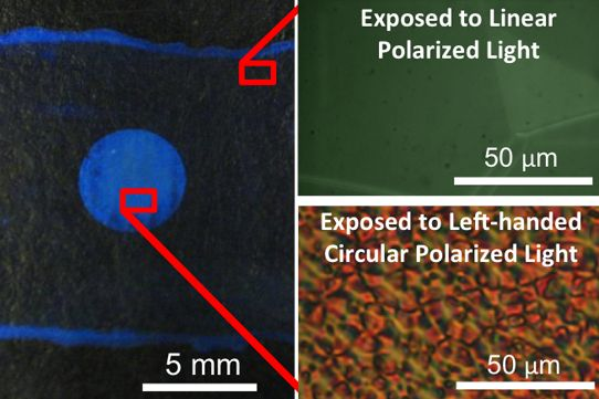
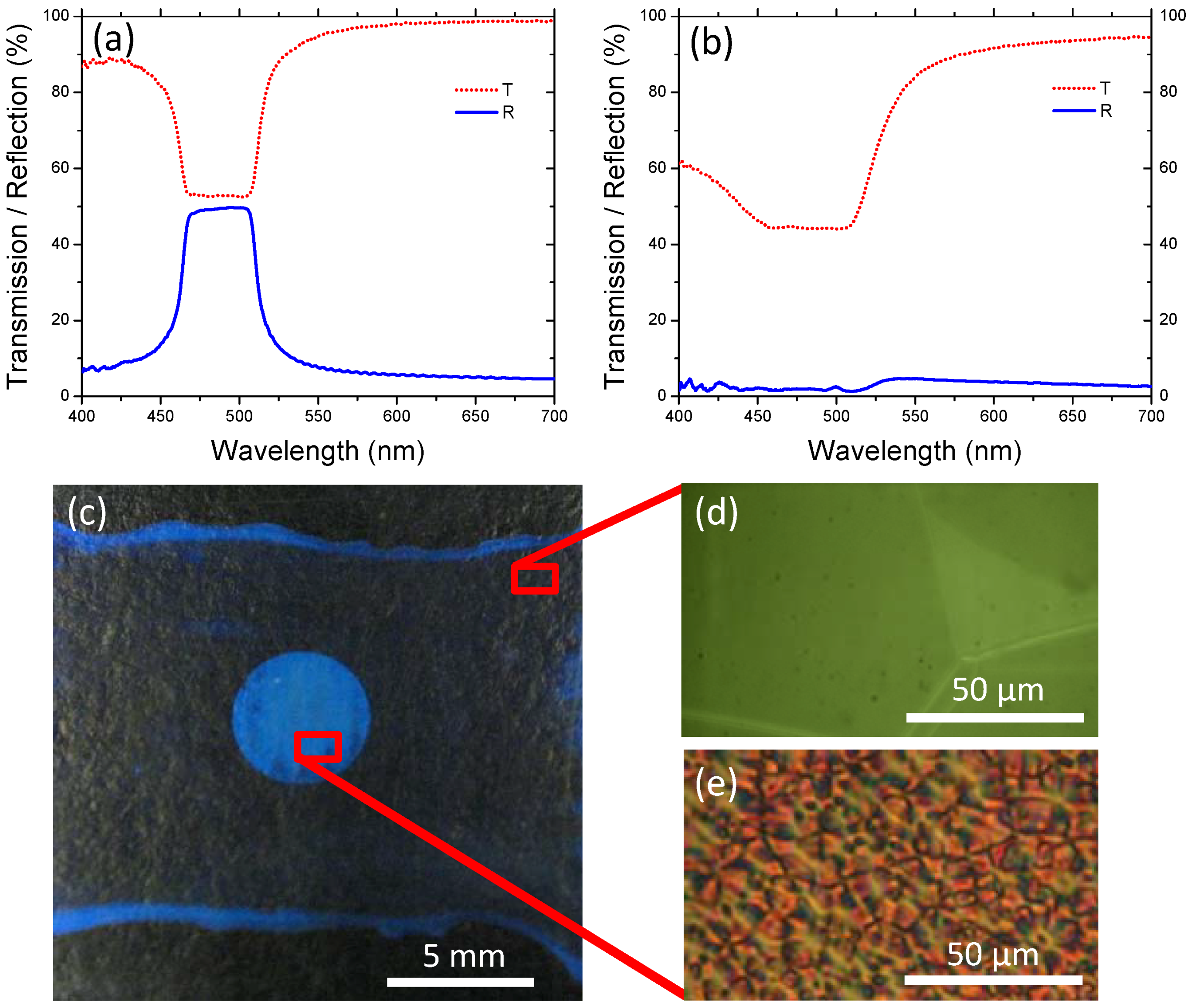
Figure 1a, indicated strong blue/green reflection centered at 485 nm. As evident in Figure 1b, exposure of this CLC cell to left-handed circularly polarized (LHCP) light of 488 nm wavelength caused a considerable decrease in the reflected intensity and a decrease in the transmitted intensity. The initially reflective cell developed a scattering spot limited to the irradiated area as exhibited by the contrast between the blue spot (scattering area) and its surroundings (off-Bragg angle reflection from well-aligned CLC) depicted in Figure 1c. A polarized optical micrograph of the initially planar, reflective Grandjean texture is shown in Figure 1d, and a micrograph of the defect-rich texture within the scattering region of the cell is shown in Figure 1e. The optically-discernable, micrometer-scale disruptions to the initially Grandjean (planar) CLC texture in the scattering regions are referred to as domains. Reflectivity of the output side of the cell remains the same after domain formation indicating that the domains are localized at the input side of the cell. Although similar in appearance to domains predicted for, and observed upon, application of electric field to CLCs, the periodicities in this work are not as uniform as in previous reports and the mechanism (CP light exposure) is unique to the literature [23,24,25,26].
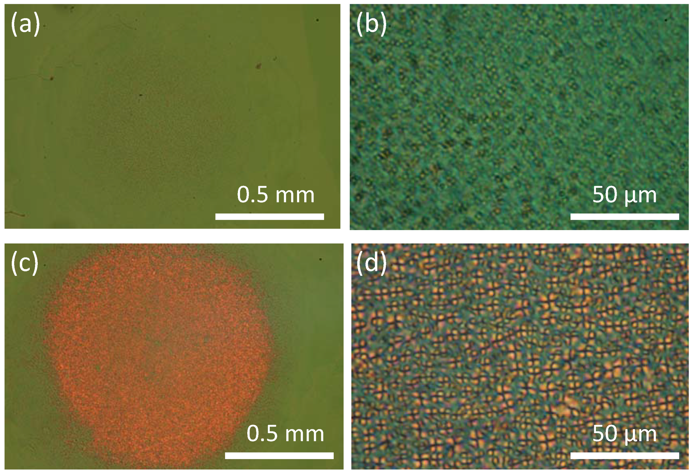
Domains start forming at an early stage of light exposure (Figure 2a,b) and fully evolve after 5 min (Figure 2c,d) for irradiation of 0.98 W/cm2 power density and 488 nm. The examination of CLC cells with PAAD-27 layer irradiated with counterpropagating LHCP beams before and after filling with CLC mixture, Figure 3, indicated in situ interaction between PAAD-27 and CLC during irradiation. The conditions of filled cell exposure were emulated for pre-filling exposure of the PAAD layer by placing a PAAD-27 coated substrate in front of non-photosensitive LH CLC reflector with selective reflection peak centered at 485 nm. Schematics of the experimental set-ups are shown in Figure 3a,b. POM micrographs of the corresponding microstructures, Figure 3c,d, show that only the area irradiated after filling exhibited domains.
Figure 1. (a) Transmission and reflection spectra from a Cholesteric liquid crystal (CLC) cell with a photosensitive layer on input substrate: (a) aligned with linearly polarized light; and (b) after 15 min exposure to 488 nm left-handed circularly polarized (LHCP) light (intensity =41 mW/cm2); (c) When imaged off of a Bragg condition the exposed spot appears blue and the rest of the aligned, reflective cell appears transparent (black background); Representative micrographs are shown of both the (d) reflective (aligned) and (e) scattering (domained) regions. Micrographs were taken in transmission mode between crossed polarizers.
Crystals 03 00234 g001
Figure 2. Temporal dependence of domain formation shown with polarized optical micrographs taken (a,b) after 1 min exposure and (c,d) after 5 min exposure.
Crystals 03 00234 g002
Figure 3. Schematic of counterpropagating 488 nm LHCP beam exposure via with reflected beam generated by (a) a non-photosensitive CLC reflector and (b) by a filled CLC with photosensitive alignment layer. Corresponding optical micrographs of same cell exposed (c) before and (d) after filling with CLC mixture. Note: QWP = quarter waveplate.
Crystals 03 00234 g003

2.2. Similarity of Optically induced Domains to the Domains Generated in CLCs with Homeotropic Boundary Conditions

The domains evident in Figure 1e, Figure 2d, Figure 3d are reminiscent of previous examinations of textures observed upon application of electric field to CLCs [26] as well as free-standing CLC films (i.e., no output substrate) [27,28,29,30]. The domains apparent in Figure 4a are typical of those previously observed at CLC/air interfaces and have been attributed to focal conical domains that form as a result of the interplay between surface tension and the anchoring/distortion energies [27,28,29,30]. The molecules periodically are orthogonal to the CLC/air interface. This out-of-plane texture is similar to that observed in cells with photogenerated domains. Additional support of homeotropic boundary conditions inducing similar defects was demonstrated by the domain texture observed in a CLC cell made with weak homeotropic orienting boundary conditions (Figure 4b). The similarities of the textures of the photogenerated domains to those observed at a CLC/air interface as well as to those in a cell with weak homeoptropic orienting conditions is evidence of the creation of out-of-plane alignment conditions in the photopatterning of scattering states.
Figure 4. (a) Micrograph of substrate coated with photosensitive alignment material (PAAD-27) layer and CLC material S811(28%)/1444 (droplet of CLC was spread in thin layer. Output substrate is absent); (b) Observation of domain structure in a CLC cell with weak homeotropic orienting boundary conditions (i.e., 4:1 PAAD(1wt% in N,N-dimethylformamide (DMF)): lecithin(1wt% in DMF) volume ratio).
Crystals 03 00234 g004

2.3. Effect of the Polarization State of Light on Photosensitive Layer

To elucidate the fundamental photochemical mechanism of domain formation, we examined the interaction of the light beam with the photosensitive orienting layer via polarized UV-Vis spectroscopy. Exposure of the photoalignment layer to linearly polarized light of a suitable wavelength (blue/green light) promoted alignment of the long axes of the chromophores in the substrate plane orthogonal to the polarization state of the light (Figure 5a) due to repeated trans-cis-trans cycling [31]. The mechanism of photo-induced reorientation is detailed in a recent review [9]. A hallmark of reorientation is photo-induced birefringence and dichroism [31]. The absorption of azobenzene-based alignment layers is maximized when the electric field vector of polarized interrogation light is parallel to the alignment direction of the long molecular axis of the trans azobenzene isomer (i.e., interrogation light polarizer angle defined at 0° in this work (see 
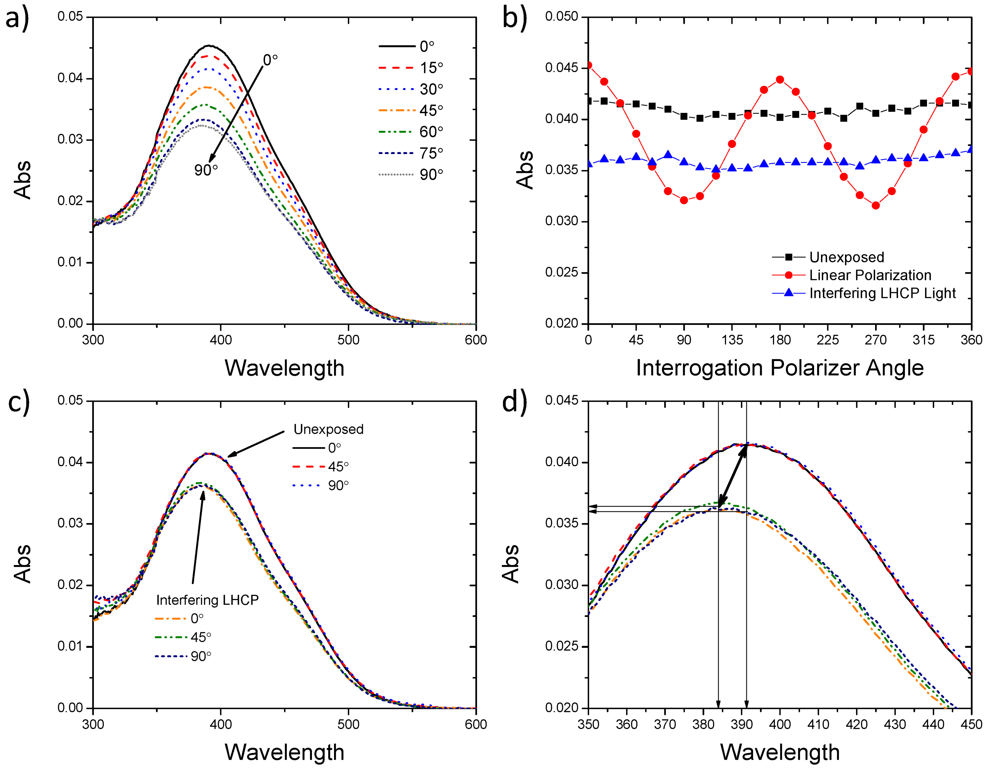
Figure 5a)). The orientation of the PAAD-27 alignment layer was interrogated via polarized UV-Vis spectroscopy after each step in a series of exposures similar to those a CLC cell would be subjected to in writing scattering regions/domains (unexposed, exposed to linearly polarized light in the y-direction, then exposed to counterpropagating LHCP light). Representative absorbance spectra generated with linearly polarized interrogation light (0°–90° in 15° increments) are shown after exposure to linearly polarized 488 nm light. In Figure 5b the absorbance values at 392 nm (average absorption maximum for unexposed PAAD-27 film) are plotted as a function of interrogation light polarization angle (y = 90°, 270°; x = 0°, 180°) after each exposure step. Polarized UV-Vis spectroscopy confirmed that the initial state of the spin coated PAAD-27 does not exhibit any preferred alignment (Figure 5b), as the absorbance of the PAAD-27 layer did not change as a function of interrogation polarizer angle. Sinusoidal variation of the magnitude of absorbance was observed in the case of preferred alignment after exposure to linearly polarized light. Specifically, after irradiation with linearly (y-direction) polarized 488 nm light the long molecular axis showed preferred orientation (i.e., in the x-direction) perpendicular to the polarization state of the laser light (Figure 5a,b). After exposure to counterpropagating (input beam and CLC-reflected beam) LHCP 488 nm light, the PAAD-27 layer once again exhibited absorbance values independent of polarizer angle accompanied by a concurrent decrease in the magnitude of average absorbance (Figure 5b).
Figure 5. (a) UV-Vis absorbance spectra of spin coated PAAD-27 film on glass substrate after exposure to linearly polarized light taken with various polarization angles of interrogation light; (b) Polarized UV-Vis plots of identical spots of PAAD-27 film taken in series: as coated (■), after exposure to linearly polarized light (488 nm, 5 mW/cm2, 15 min) (●), and after exposure to counterpropagating LHCP beams(488 nm, 5 mW/cm2, 15 min) (▲); (c,d) Absorbance spectra taken with interrogation polarizer at 0°, 45° and 90° of PAAD-27 as coated versus after exposure to counterpropagating LHCP light. Note: (d) is a portion of the spectra shown in (c).
Crystals 03 00234 g005
Unpolarized and circularly polarized light have been reported to randomize chromophore orientations [31]. The average decrease in absorbance is attributed to some preferential alignment along the radiation propagation axis (i.e., out-of-plane or along z-axis) [31]. Three of the unexposed absorbance spectra and three spectra obtained after counterpropagating LHCP light exposure absorbance spectra are presented in Figure 5c, showing a decrease in absorption for the entire peak and a peak blue-shift after exposure. Each exposure state demonstrated nicely overlapping absorbance spectra for 0°, 45°, and 90° interrogation polarizer angles as expected from isotropic alignment (Figure 5c,d). Zooming in on the peaks in Figure 5d reveals that choosing a fixed wavelength for determining absorbance may contribute artificial loss in absorbance due to peak shift. For each exposure step the absorbance was measured at 392 nm and 384 nm. Peak to peak shifting, 392 nm (unexposed) → 384 nm (after counterpropagating LHCP) showed an only 8% decrease in the average absorbance loss when compared to the loss measured for both cases at 392 nm. Thus the bulk of the loss in absorbance after exposure is attributed to out-of-plane alignment of the chromophores along the irradiation axis. The blue-shift evident in Figure 5c,d is potentially attributed to changes in trans-/cis-isomer concentration and/or the parallel alignment of chromophores referred to as H-aggregates [31,32,33,34].
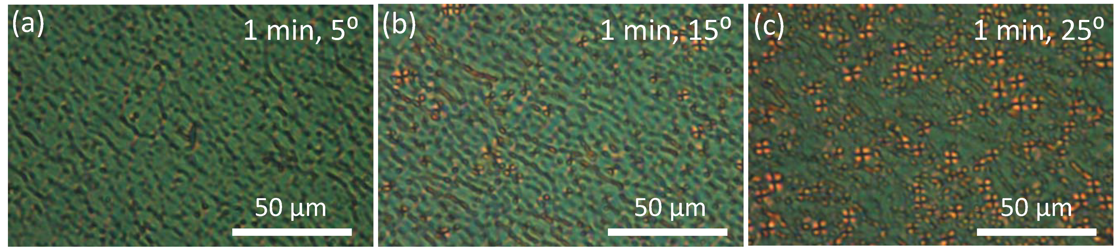
At oblique incidence, even unpolarized light can induce pre-tilt of LC molecules adjacent to a photoalignment surface [31,35]. All polarization states of incident light have shown the propensity to promote some out-of-plane alignment but only counterpropagating CP beams of same handedness have been shown to generate domains [22]. By tilting the CLC cell, an increased efficiency of domain formation with increased tilt angle was observed (Figure 6a–c).
Figure 6. Effect of angle of incident irradiation (a) 5°; (b) 15°; and (c) 25° on domain formation after 1 min exposure.
Crystals 03 00234 g006

2.4. Frustrated Photoalignment

We can thus draw the following general picture for the phenomenon under discussion. Counterpropagating LHCP beams (the incident beam and the beam reflected from the CLC) overlap creating a spiral standing wave—a linear polarization state that is rotating along the irradiation propagation axis (Figure S1). It degrades the planar alignment condition near the boundary. This diminishes the bandgap reflection, thus the standing wave and the resulting linear polarization state acting at the boundary layer is lost (Figure S2). Since the incident CP light itself does not have an appreciable in-plane alignment effect on boundary conditions, the resultant textured state of the CLC is preserved.
The photosensitive alignment layer of the CLC cell, being only a few nanometers thin, is actually subject to effectively linear polarized light in the case of normal incidence or to a polarization modulation pattern if the cell is tilted with respect to the propagation direction of the beams and thus intersects the standing wave at planes corresponding to different polarization states. Experiments show that linearly polarized incident beam does not cause domain formation and can eliminate the textures [22]. To test a hypothesis that the domain formation may have been caused by spatially modulated alignment conditions, the CLC was exposed to a laser beam propagated through a linear-to-cycloidal polarization converter [
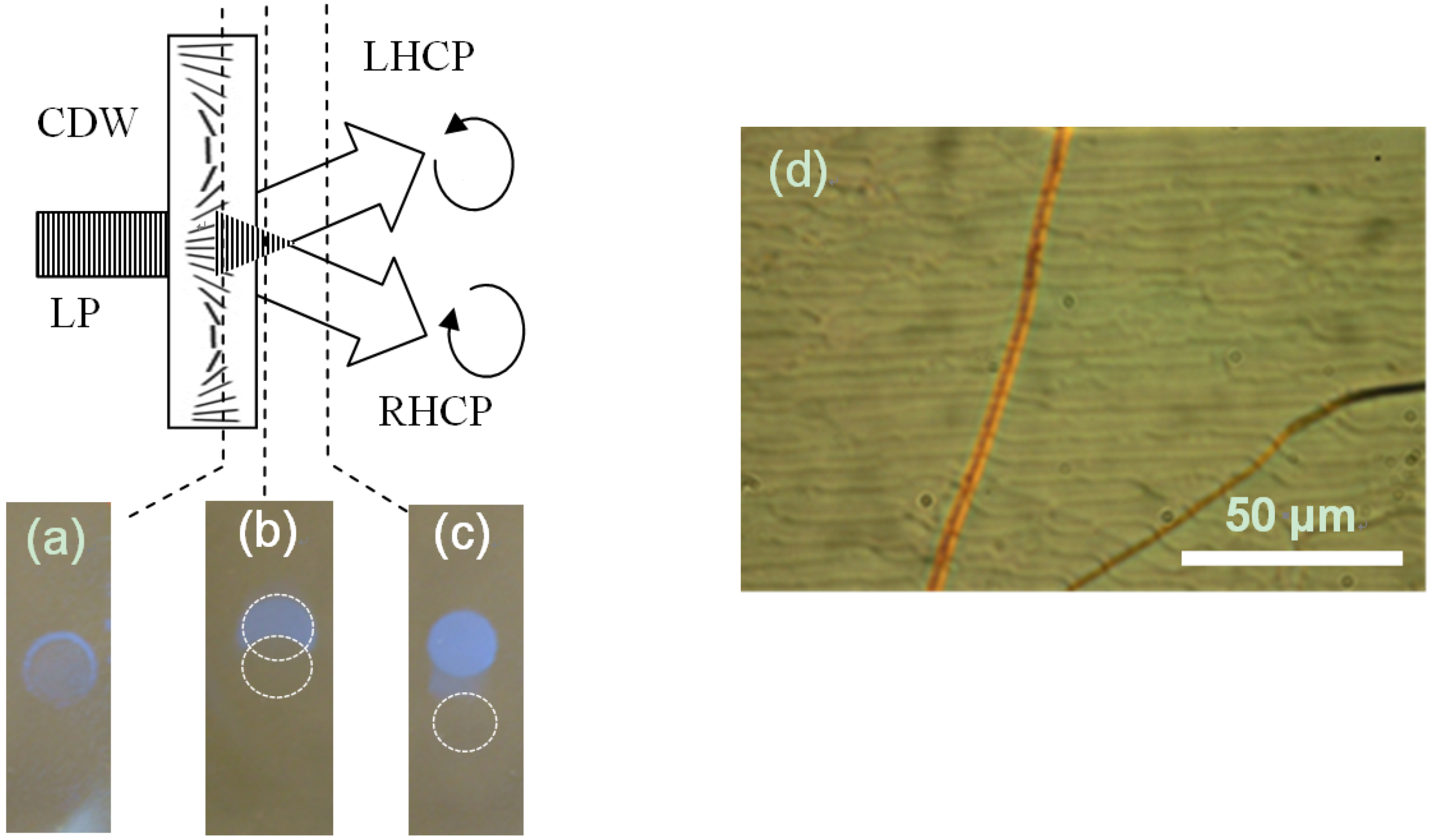
36]. A cycloidal diffractive waveplate (CDW) was used for the purpose. The waveplate splits an input linear polarized light into ±1st diffraction orders of orthogonal circular polarization states. Spatially rotating linear polarization pattern (with 6 μm pitch in the particular case) is obtained at the overlap region of the beams, however, no domain-like textures are generated in this area or in the area subject to the RHCP beam as shown in Figure 7.
Figure 7. Exposing the interface of a CLC with the photosensitive boundary of the cell to spatially modulated linear polarization pattern obtained at the output of a linear-to-cycloidal polarization converter. (a) The interface is in the polarization modulation pattern present at the overlap region of right- and left-circular polarized beams outputted by the cycloidal diffractive waveplate (CDW). The latter acts as a polarization converter for a linear polarized (LP) incident beam; (b) The interface is in the partial overlap region of the orthogonal circular polarized beams; (c) The interface is out of overlap region of the orthogonal circular polarized beams. Domains are present only in area subject to LHCP beam outside of the overlap area; (d) Grating structure formed in the overlap area of the beams.
Crystals 03 00234 g007
A linear polarized input, modulated or not, does not induce domain formation. To reconcile this statement with the observation that only bandgap mode CP light induces domains (Note: the initial overlap of input and reflected beams creates a linear polarization state at the photosensitive alignment layer), we need to assume that realignment of the PAAD molecules at the influence of a linear polarized light has a transient state. With no feedback (i.e., change in polarization state), the light remains linearly polarized accomplishing the transition to the new oriented state. With frustrated feedback (
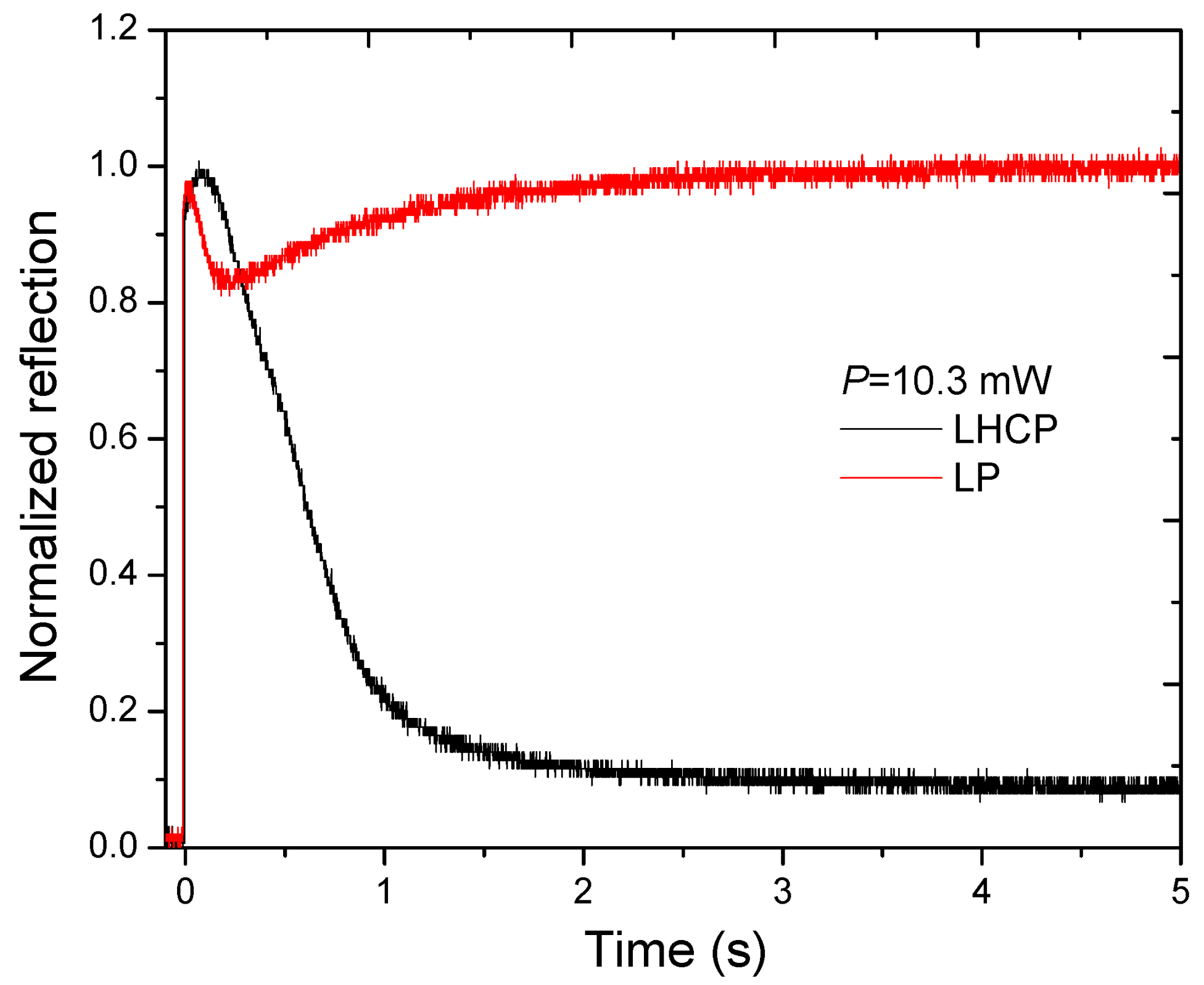
i.e., change in polarization state due to loss of reflected beam), the domained state is preserved. This was proven directly by registering the reflection dynamics for a linear polarized beam incident on the CLC, Figure 8. The reflection of the CLC when exposed to a linearly polarized beam decreased at the initial stages of the process followed by relaxation to the highly reflective state. In contrast, the decrease in the reflection continues for the circular polarized input.
Figure 8. Reflection dynamics of CLC upon exposure with linearly polarized (LP) and left-handed circularly polarized (LHCP) (wavelength = 488 nm, Intensity = 1.2 W/cm2).
Crystals 03 00234 g008
The origins of the transient state that results in photogenerated domain formation is apparently a pretilt induced by the PAAD due to statistical accumulation of PAAD molecules in a direction perpendicular to the polarization of light, which includes the direction normal to the substrates [37]. The formation of domains of similar texture at a CLC/air interface or with a weak homeotropic boundary condition (PAAD/lecithin alignment layer) is evidence for this hypothesis. The UV-Vis spectroscopic data provides evidence for out-of-plane alignment which also supports this working hypothesis.

3. Experimental Methods

Making mixtures and CLC cells: The cholesteric liquid crystal (CLC) mixture was composed of a nematic liquid crystal host, MDA-00-1444 (Merck), and a non-photosensitive left-handed (LH) chiral dopant, S811 (Merck). The helical twisting power of the chiral dopant in this nematic LC host was ~11.7 μm−1. The reflection peak of this CLC mixture was centered about 485 nm (28.0% S811). The planar orientation on the input substrate (i.e., substrate closest to incident light irradiation direction) was obtained by spin coating one side of a glass substrate vacuum chucked in a wafer spinner (Spin 150, Semiconductor Production Systems) with commercially available, azobenzene-based photoalignment material, PAAD-27 (BEAM Company, USA). Specifically, PAAD-27 (1 wt %) was dissolved in N,N-dimethylformamide (DMF) and was spin coated for 30 s at 2000 rpm. The process further included drying at 100 °C for 20 min and exposing the azobenzene-based layer to a linearly polarized LED light of 459 nm wavelength and 10 mW cm−2 power density for 15 min. Such alignment can occur before or after constructing a cell. The output substrate was spin-coated (1500 rpm for 15 s and then 3000 rpm for 60 s) with a solution of polyvinyl alcohol (PVA) (0.5 wt %) in distilled water, dried and then uniaxially rubbed with a felt cloth. Some output substrates were coated with polyimide solution [PI-2555 (HD MicroSystems) (8 mL) with reagent grade N-Methyl-2-pyrrolidone (32.5 mL) and reagent grade1-Methoxy-2-propanol (9.1 mL).] The polyimide solution was applied via syringe outfitted with a 0.45 µm GHP membrane (Pall Acrodisc) filter. Spin coating was conducted in a wafer spinner at 1500 rpm for 15 s and then 3000 rpm for 60 s. Coated glass substrates were then dried on a hotplate for 30 min at 200 °C and rubbed with a felt cloth. Cell thickness was set using 20 µm silica rod spacers (PF-200, Nippon Electric Glass Company, Ltd.). Cells were constructed with one PAAD-27 coated input substrate and either one rubbed PVA or PI output substrate. CLC mixture was drawn into self-prepared cells above the clearing temperature (80 °C) and allowed to cool ~1°C/min to room temperature.
Optical Characterization: Optical micrographs were taken with an inverted Olympus IX51 microscope in transmission mode through crossed polarizers. Photographs were taken with a 7.1 mega pixel PowerShot A710 IS digital camera (Canon USA) with both the macro feature and image stabilizer enabled (no flash). Domain formation was achieved in optical set-up depicted in Figure 9. For tilt and time experiments no beam expander was utilized. The beam radius of the Ar+ laser was 0.33 mm if unmodified or set via an aperture after a beam expander. The linear polarization of the beam was converted into circular polarization using a quarter waveplate, QWP. Periaxial reflection and transmission spectra (shown in Figure 1a,b) were taken before and after exposure to LHCP 488 nm light (intensity = 41 mW/cm2). Power measurements were made with PM100A power meter and S302C detector (Thorlabs, Inc.). The tungsten halogen lamp source (LS-1, Ocean Optics) was incident normal to the CLC cell. USB2000+ VIS-NIR spectrometers (Ocean Optics, Inc.) collected reflection and transmission spectra.
Figure 9. Experimental set-up utilized for cell exposure. Exposure time and angle dependence did not utilize beam expander and aperture whereas larger area exposures utilized for generating spectra and UV-Vis data did utilize beam expander and aperture. IF—interference filter; QWP—quarter waveplate.
Crystals 03 00234 g009
PAAD-27 was spin coated on CCC166 uncoated 25 mm × 38 mm × 1.1 mm plates of EXG Boro-Aluminosilicate glass (Corning) and was interrogated in a Cary 5000 UV-Vis-NIR spectrophotometer. The PAAD-27 substrate was mounted onto a sample holder with a 5 mm interrogation spot defined by a metal aperture. Two identical holders were used to mount identical uncoated glass plates. One uncoated plate was placed in the reference beam path and the other was used to establish a baseline scan such that the only difference in the interrogation and reference optical paths was a polarizer. A baseline scan was taken before each absorbance spectra taken at a given polarizer angle. The PAAD-27 coated substrate was exposed in series (same set-up as Figure 9 with target being PAAD-27 coated glass rather than CLC and the aperture being intrinsic to sample holder rather than immediately following the beam expander) and was not removed from the sample holder to ensure the same spot was interrogated throughout the experiment. Each exposure passed through the sample holder aperture then through sample with PAAD-27 layer on output side of coated slide. A counterpropagating beam was generated with a non-photosensitive CLC reflector (LH CLC with selective reflection centered about 485 nm). All exposures were 15 min and utilized 488 nm light with an intensity of 5 mW/cm2. Note: When exposing CLC cell with PAAD-27 coated input substrate an absorptive ND filter (optical density = 0.4 at 546.1 nm, Newport Corporation) was mated to output substrate surface with index matching fluid (Series A RI fluid, nd = 1.520 ± 0.002, Cargille Laboratories). When stacking PAAD-coated slide and CLC reflector the components were also mated together with index matching fluid and an ND filter was mated to the output surface of the CLC reflector (See Figure 4a).

4. Summary

Circularly polarized light irradiation of cholesteric liquid crystal cells, fabricated with a photoalignment layer, led to the formation of scattering areas. Within such a scattering area, domains were shown to exhibit similar appearance to textures observed in a CLC cell with weak homeotropic boundary conditions as well as in a free-standing CLC film. The results presented here elucidate the complex interplay amongst the stimulus irradiation, photoalignment surface, and resulting organization of the CLC film. Building from the prior confirmation of the prerequisite conditions necessary to cause domain formation, this work demonstrated that the underlying mechanism for generating scattering states in CLC films is attributable to out-of-plane reorientation of a portion of the photosensitive alignment material. The contribution of this out-of-plane alignment in conjunction with disruption to the alignment of the in-plane chromophores resulted in a scattering state in the CLC, and consequently, a change in the polarization state of the light seen at the photosensitive layer. Optical writing of reflective/scattering states is reversible (erasable with linearly polarized light) and reconfigurable (new patterns can be written with CP light) since it is mediated by an azobenzene-based surface layer. The ability to pattern and reconfigure reflective/scattering states within a CLC is expected to be useful for systems where all optical control of dynamic information is needed.

Acknowledgments

This work was funded by the Air Force Office of Scientific Research and the Materials and Manufacturing Directorate of the Air Force Research Laboratory. The authors are thankful to Deng-Ke Yang and Michael E. McConney for helpful discussions.

Conflict of Interest

The authors declare no conflict of interest.

References

  1. Collings, P.J. Liquid Crystals: Nature’s Delicate Phase of Matter, 2nd ed; Princeton University Press: Princeton, NJ, USA, 2002; pp. 9–10. [Google Scholar]
  2. Belyakov, V.A.; Dmitrienko, V.E. Optics of Chiral Liquid Crystals, 1st ed; Routledge: Harwood, NY, USA, 1989. [Google Scholar]
  3. St. John, W.D.; Fritz, W.J.; Lu, Z.J.; Yang, D.-K. Bragg reflection form cholesteric liquid crystals. Phys. Rev. E 1995, 51, 1191–1198. [Google Scholar] [CrossRef]
  4. Sharma, V.; Crne, M.; Park, J.O.; Srinivasarao, M. Structural Origin of Circularly Polarized Iridescence in Jeweled Beetles. Science 2009, 325, 449–110. [Google Scholar] [CrossRef]
  5. Vignolini, S.; Rudall, P.J.; Rowland, A.V.; Reed, A.; Moyroud, E.; Faden, R.B.; Baumberg, J.J.; Glover, B.J.; Steiner, U. Pointillist structural color in Pollia fruit. Proc. Natl. Acad. Sci. USA 2012, 109, 15712–15715. [Google Scholar] [CrossRef]
  6. Fan, B.; Vartak, S.; Eakin, J.N.; Faris, S.M. Surface anchoring effects on spectral broadening of cholesteric liquid crystal films. J. Appl. Phys. 2008, 104, 023108:1–023108:5. [Google Scholar]
  7. Chigrinov, V.G.; Kozenkov, V.M.; Kwok, H.-S. Photoalignment of Liquid Crystalline Materials: Physics and Applications, 1st ed; John Wiley and Sons Ltd.: West Sussex, UK, 2008; p. 5. [Google Scholar]
  8. Ichimura, K. Photoalignment of Liquid-Crystal Systems. Chem. Rev. 2000, 100, 1847–1873. [Google Scholar] [CrossRef]
  9. Yaroshchuk, O.; Reznikov, Y. Photoalignment of liquid crystals: Basics and current trends. J. Mater. Chem. 2012, 22, 286–300. [Google Scholar] [CrossRef]
  10. Gibbons, W.M.; Shannon, P.J.; Sun, S.-T.; Swetlin, B.J. Surface-mediated alignment of nematic liquid crystals with polarized laser light. Nature 1991, 351, 49–50. [Google Scholar]
  11. Schadt, M.; Schmitt, K.; Kozinkov, V.; Chigrinov, V. Surface-induced parallel alignment of liquid crystals by linearly polymerized photopolymer. J. Appl. Phys. 1992, 31, 2155–2164. [Google Scholar]
  12. Marusii, T.Y.; Reznikov, Y.A. Photosensitive orientants for liquid crystal alignment. Mol. Mater. 1993, 3, 161–168. [Google Scholar]
  13. Sung, S.-J.; Cho, K.-Y.; Park, J.-K. Photo-induced liquid crystal alignment of poly(vinyl cinnamate) and fluorinated polyimide blends. Mater. Sci. Eng. C 2004, 24, 181–184. [Google Scholar] [CrossRef]
  14. Hah, H.; Sung, S.-J.; Park, J.-K. Ultraviolet embossed alignment layer for flexible liquid crystal display. Appl. Phys. Lett. 2007, 90, 063508:1–063508:3. [Google Scholar]
  15. Hah, H.; Sung, H.-J.; Cho, K.Y.; Park, J.-K. Molecular orientation of liquid crystal on polymer blends of coumarin and naphthalenic polyimide. Polym. Bull. 2008, 61, 383–390. [Google Scholar] [CrossRef]
  16. Ichimura, K.; Akiyama, H.; Ishizuki, N.; Kawanishi, Y. Command surfaces, 6 Azimuthal orientation of liquid crystals photo-controlled by an azobenzene pendent polymer. Makromol. Chem. Rapid Commun. 1993, 14, 813–817. [Google Scholar] [CrossRef]
  17. Zhong, Z.-X.; Li, X.; Lee, S.H.; Lee, M.-H. Liquid crystal photoalignment material based on chloromethylated polyimide. Appl. Phys. Lett. 2004, 85, 2520–2523. [Google Scholar] [CrossRef]
  18. Kurochkin, O.; Ouskova, E.; Reznikov, Y.; Kurioz, Y.; Tereshchenko, O.; Vovk, R.; Kim, D.-H.; Park, S.-K.; Kwon, S.-B. Light-Controlled Alignment of Cholesteric Liquid Crystals on Photoresponsive Materials. Mol. Cryst. Liq. Cryst. 2006, 453, 333–341. [Google Scholar] [CrossRef]
  19. Nersisyan, S.R.; Tabiryan, N.V. Polarization imaging components based on patterned photoalignment. Mol. Cryst. Liq. Cryst. 2008, 489, 156–168. [Google Scholar]
  20. Lin, T.-H.; Huang, Y.; Zhou, Y.; Fuh, A.Y.G.; Wu, S.-T. Photo-patterning micro-mirror devices using azo dye-doped cholesteric liquid crystals. Opt. Express 2006, 14, 4479–4485. [Google Scholar] [CrossRef]
  21. Tabiryan, N.V.; Nersisyan, S.R.; Steeves, D.M.; Kimball, B.R. The Promise of Diffractive Waveplates. Opt. Photon. News 2010, 21, 41–45. [Google Scholar] [CrossRef]
  22. Vernon, J.P.; Hrozhyk, U.A.; Serak, S.V.; Tondiglia, V.P.; White, T.J.; Tabiryan, N.V.; Bunning, T.J. Optically reconfigurable reflective/scattering states enabled with photosensitive cholesteric liquid crystal cells. Adv. Opt. Mater. 2013, 1, 84–91. [Google Scholar]
  23. Helfrich, W. Deformation of Cholesteric Liquid Crystals with Low Threshold Voltage. Appl. Phys. Lett. 1970, 17, 531–532. [Google Scholar] [CrossRef]
  24. Gerritsma, C.J.; van Zanten, P. Periodic Perturbations in the Cholesteric Plane Texture. Phys. Lett. A 1971, 37, 47–48. [Google Scholar] [CrossRef]
  25. Hervet, H.; Hurault, J.P.; Rondelez, F. Static one-dimensional distortions in cholesteric liquid crystals. Phys. Rev. A 1973, 8, 3055–3064. [Google Scholar] [CrossRef]
  26. Senyuk, B.I.; Smalyukh, I.I.; Lavrentovich, O.D. Undulations of lamellar liquid crystals with finite surface anchoring near and well above the threshold. Phys. Rev. E 2006, 74, 011712:1–011712:13. [Google Scholar]
  27. Saupe, A. Disclinations and properties of the directorfield in nematic and cholesteric liquid crystals. Mol. Cryst. Liq. Cryst. 1973, 21, 211–238. [Google Scholar] [CrossRef]
  28. Bunning, T.J.; Vezie, D.L.; Lloyd, P.F.; Haaland, P.D.; Thomas, E.L.; Adams, W.W. Cholesteric Liquid Crystals image contrast in the TEM. Liq. Cryst. 1994, 16, 769–781. [Google Scholar] [CrossRef]
  29. Meister, R.; Dumoulin, H.; Halle, M.-A.; Pieranski, P. Structure of the cholesteric focal conic domains at the free surface. Phys. Rev. E 1996, 54, 3771–3782. [Google Scholar] [CrossRef]
  30. Meister, R.; Dumoulin, H.; Halle, M.-A.; Pieranski, P. The Anchoring of a Cholesteric Liquid Crystal at the Free Surface. J. Phys. II Fr. 1996, 6, 827–844. [Google Scholar]
  31. Yager, K.G.; Barrett, C.J. Azobenzene Polymers for Photonic Applications. In Smart Light-Responsive Materials, 1st; Zhao, Y., Ikeda, T., Eds.; John Wiley and Sons, Inc.: Hoboken, NJ, USA, 2009; pp. 1–46. [Google Scholar]
  32. Markave, E.; Gustina, D.; Matixova, G.; Kaula, I.; Muzikante, I.; Rutkis, M.; Gerca, L. Reversible trans/cis photoisomerization in Langmuir-Blodgett multilayers from polyfunctional azobenzenes. Supramol. Sci. 1997, 4, 369–374. [Google Scholar] [CrossRef]
  33. Menzel, H.; Weichart, B.; Schmidt, A.; Paul, S.; Knoll, W.; Stumpe, J.; Fischer, T. Small-angle X-ray scattering and ultraviolet-visible spectroscopy studies on the structure and structural changes in Langmuir-Blodgett films of polyglutamates with azobenzene moieties tethered by alkyl spacers of different length. Langmuir 1994, 10, 1926–1933. [Google Scholar] [CrossRef]
  34. Cojocariu, C.; Rochon, R. Light-induced motions in azobenzene-containing polymers. Pure Appl. Chem. 2004, 76, 1479–1497. [Google Scholar] [CrossRef]
  35. Ruslim, C.; Ichimura, K. Photocontrolled Alignment of Chiral Nematic Liquid Crystals. Adv. Mater. 2001, 13, 641–644. [Google Scholar] [CrossRef]
  36. Nersisyan, S.R.; Tabiryan, N.V.; Steeves, D.M.; Kimball, B.R. Characterization of optically imprinted polarization gratings. Appl. Opt. 2009, 48, 4062–4067. [Google Scholar] [CrossRef]
  37. Serak, S.; Tabiryan, N. Microwatt Power Optically Controlled Spatial Solitons in Azobenzene Liquid Crystals. Proc. SPIE 2006, 6332, 63320Y:1–63320Y:13. [Google Scholar]

