Nanomaterials in Liquid Crystals as Ion-Generating and Ion-Capturing Objects


1
UCCS BioFrontiers Center, University of Colorado Colorado Springs, Colorado Springs, CO 80918, USA
2
Department of Physics, University of Colorado Colorado Springs, Colorado Springs, CO 80918, USA
Crystals 2018, 8(7), 264; https://0-doi-org.brum.beds.ac.uk/10.3390/cryst8070264
Submission received: 7 June 2018
/
Revised: 22 June 2018
/
Accepted: 22 June 2018
/
Published: 26 June 2018
(This article belongs to the Special Issue Selected Papers from "The 1st International Electronic Conference on Crystals")
Abstract
:The majority of tunable liquid crystal devices are driven by electric fields. The performance of such devices can be altered by the presence of small amounts of ions in liquid crystals. Therefore, the understanding of possible sources of ions in liquid crystal materials is very critical to a broad range of existing and future applications employing liquid crystals. Recently, nanomaterials in liquid crystals have emerged as a hot research topic, promising for its implementation in the design of wearable and tunable liquid crystal devices. An analysis of published results revealed that nanodopants in liquid crystals can act as either ion-capturing agents or ion-generating objects. In this paper, a recently developed model of contaminated nanomaterials in liquid crystals is analyzed. Nanoparticle-enabled ion capturing and ion generation regimes in liquid crystals are discussed within the framework of the proposed model. This model is in very good agreement with existing experimental results. Practical implications and future research directions are also discussed.
1. Introduction
A great variety of existing liquid crystal devices relies on reorientation effects when applied electric fields change the orientation of mesogenic molecules [1]. These devices include liquid crystal displays (LCD) [2], tunable optical elements, such as filters [3], retarders [3], waveplates [4], lenses [5], and optical switches [6], to name a few. The performance of the aforementioned devices can be altered by mobile ions, typically present in liquid crystals, through the screening effect [2,7,8]. In the case of liquid crystal displays, this screening effect can result in an image sticking, image flickering, reduced voltage holding ration, and overall slow response of the display [2,8]. That is why it is of a paramount importance to understand possible sources of ion generation in liquid crystals [7,8,9].
Sources of ions in liquid crystals can be of different origin [7,8,9,10]. Ionic species can be deliberately added to liquid crystals [10,11,12]. Such ionic dopants (for example, tetrabutylammonium tetraphenylboride) in liquid crystals were extensively studied back in the 1970s [11,12]. Small traces of ions (metal ions and inorganic anions) in liquid crystals can originate during chemical synthesis [13,14]. Alignment layers and glue used to seal liquid crystal cells are also important sources of ions in liquid crystals [15,16,17,18]. External factors, such as electric fields [19,20,21,22] and ionizing radiation [23,24], can enrich liquid crystals with ions. Electrochemical reactions taking place in the near-electrode areas can also generate ions in liquid crystals [25,26,27].
Recently, nanomaterials in liquid crystals became a hot research topic with a rapidly increasing number of publications (more details can be found in numerous review papers [28,29,30,31,32,33,34,35,36,37,38], and collective monographs [39,40]). Accumulated research data reviewed in paper [41] indicate that nanomaterials in liquid crystals can alter the behavior of ions in liquid crystals. It was reported by different research groups that carbon-based nano-objects [41,42,43,44], metal [41,45,46,47,48], dielectric [41,49,50,51,52], semiconductor [41,53,54], ferroelectric [41,55,56,57,58,59,60], and other nanomaterials [41], can change the concentration of ions in liquid crystals. In many reported cases, nano-objects in liquid crystals can behave as ion-capturing objects, thus decreasing the concentration of mobile ions in liquid crystals [41]. Interestingly, in many other cases, nanodopants in liquid crystals act as a source of ions, increasing the concentration of mobile ions [41].
In an attempt to explain different, even seemingly contradictory reported results, a concept of contaminated nanomaterials was introduced [61]. In short, nanoparticles were considered contaminated with ions in liquid crystals prior to dispersing them in liquid crystals [61]. This simple approach, applied to a variety of existing experimental results, shows very good agreement between the modelled and experimental data [61,62]. By dispersing contaminated nanodopants in liquid crystals, three different regimes, namely, the ion capturing regime (nanoparticles decrease the concentration of mobile ions in liquid crystals), the ion-releasing or ion-generation regime (nanomaterials increase the concentration of mobile ions in liquid crystals), and no change regime, can be achieved [61]. The model of contaminated nanomaterials was extended to account for several types of dominant ions in liquid crystals [63,64], for possible temperature-induced effects [65,66], for weakly-ionized ionic species [67], and for the presence of substrates [68]. In addition, the kinetics of ion-capturing/ion-releasing processes in liquid crystals doped with nanomaterials [69], and ion-trapping coefficients of nanodopants [70] were also discussed.
All these results indicate that, generally, we have to consider nanomaterials as a very important source of ions or ion traps in liquid crystals [71]. The goal of this review paper is to summarize the most important features of the model of contaminated nanomaterials in liquid crystals [61,62,63,64,65,66,67,68,69,70,71,72] in the form of a brief tutorial accessible to a broad scientific audience.
2. Results and Discussion
2.1. Model
Consider nanoparticles in a liquid crystal host. In the most general case, these nanoparticles can be contaminated with ions prior to dispersing them in liquid crystals. To account for this ionic contamination of nanoparticles, a contamination factor is introduced [61]. It equals a ratio of the number of surface sites of nanoparticle occupied by ionic contaminants to the total number of all surface sites of nanoparticle [61]. Typically, the number of surface sites can be characterized by their surface density . Once contaminated nanoparticles are dispersed in liquid crystals, some fraction of ions can be released from their surface, whereas some fraction of ions present in liquid crystals can be captured by nanoparticles. To simplify the discussion, consider the case of fully ionized ionic species characterized by their volume concentration, . In this case, the competition between ion-capturing and ion-releasing processes will result in the change of the concentration of mobile ions in liquid crystals doped with nanoparticles. In many practical cases, the ion-releasing process can be associated with desorption of ions from nanoparticles, and the ion-capturing process can be described as adsorption of ions onto the surface of nanoparticles. As a result, the following rate Equation (1) can be applied [69]:
In this equation, is the concentration of mobile ions in liquid crystals doped with nanoparticles; denotes time; is the volume concentration of nanoparticles in liquid crystals; is the aforementioned surface density of all adsorption sites of a single nanoparticle; is its surface area (for simplicity, spherical nanoparticles of a radius are assumed); is the fractional surface coverage of nanoparticles; is the adsorption rate constant; and is the desorption rate constant. In the majority of the reported experimental studies, weight concentration of nanoparticles is used instead of their volume concentration . They are related as , where () is the density of liquid crystals (nanoparticles) and is the volume of a single nanoparticle.
The first term of Equation (1) accounts for the ion-capturing process, whereas the second term originates from the ion-releasing phenomenon. This equation should be solved considering the conservation law of the total number of ions (Equation (2)):
In Equation (2), is the initial concentration of mobile ions in liquid crystals (prior to doping them with nanomaterials); and is the aforementioned contamination factor of nanoparticles. It accounts for possible contamination of nanodopants with ions [61].
It should be stressed that Equation (1) is an approximation which can be applied to liquid crystals doped with nanoparticles with certain restrictions discussed in recent papers [64,67,72]. In a general case, a more rigorous approach based on Boltzmann–Poisson equation should be considered [73,74,75,76].
Equations (1) and (2) can also be generalized to account for several types of dominant ions in liquid crystals [63,64]. In the simplest case of two dominant types of fully ionized ionic species characterized by their volume concentrations, and , the system of Equations (3) and (4) can be used (; the meaning of physical quantities entering these equations are similar to that of Equations (1) and (2) [61,63,64]):
2.2. Kinetics of Ion-Capturing and Ion-Releasing Processes
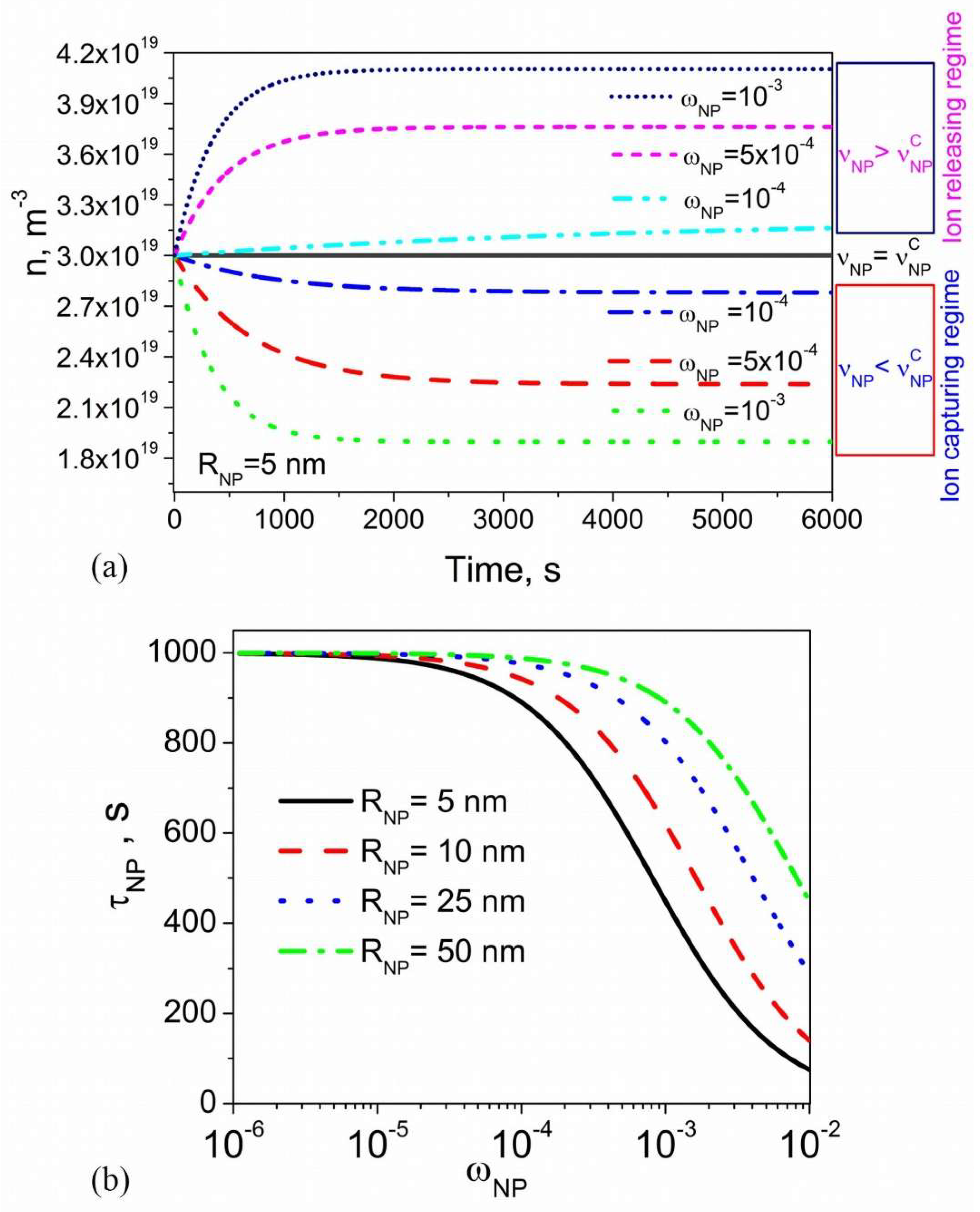
The kinetics of ion-capturing and ion-releasing processes in liquid crystals doped with nanoparticles was analyzed in a recent paper [69]. This analysis was based on Equations (1) and (2), and the results are shown in Figure 1 [69].
According to Figure 1a, depending on the level of ionic contamination of nanoparticles, three different regimes can be achieved: the ion releasing regime, (dashed–dotted–dotted, short-dashed, and short-dotted curves); ion capturing regime, (dotted, dashed, and dashed–dotted curves); and no change regime, (solid curve). The ionic contamination of nanoparticles quantified by the contamination factor governs the switching between these regimes. The ion releasing regime is observed if , the ion capturing regime holds true if , and no change regime is reached if , where is the critical contamination factor of nanoparticles. It is defined as where [69]. Figure 1a also indicates that both ion-capturing and ion-releasing regimes depend on the concentration of nanoparticles: they are more pronounced if higher concentrations are used.
The time constant characterizing the kinetics of ion-capturing/ion-releasing process shown in Figure 1a can be defined through Equation (5):
where and . In the regime of low surface coverage () this time constant is given by Equation (6):
In the case of spherical nanoparticles of radius , the dependence of the time constant on the weight concentration of nanodopants is shown in Figure 1b. As can be seen, by using smaller nanoparticles and their higher concentrations, one can decrease the time needed to achieve the steady-state. However, it should be noted that this decrease is diffusion-limited. In other words, Equation (6) is correct as long as . The characteristic time can be estimated by means of Equation (7):
where is the average distance between mobile ions in liquid crystals, and is the diffusion coefficient of ions. By using typical values ( and m2/s [13]), this time can be estimated as s. By comparing it to data shown in Figure 1b it can be seen that, indeed, .
2.3. Steady-State Regime
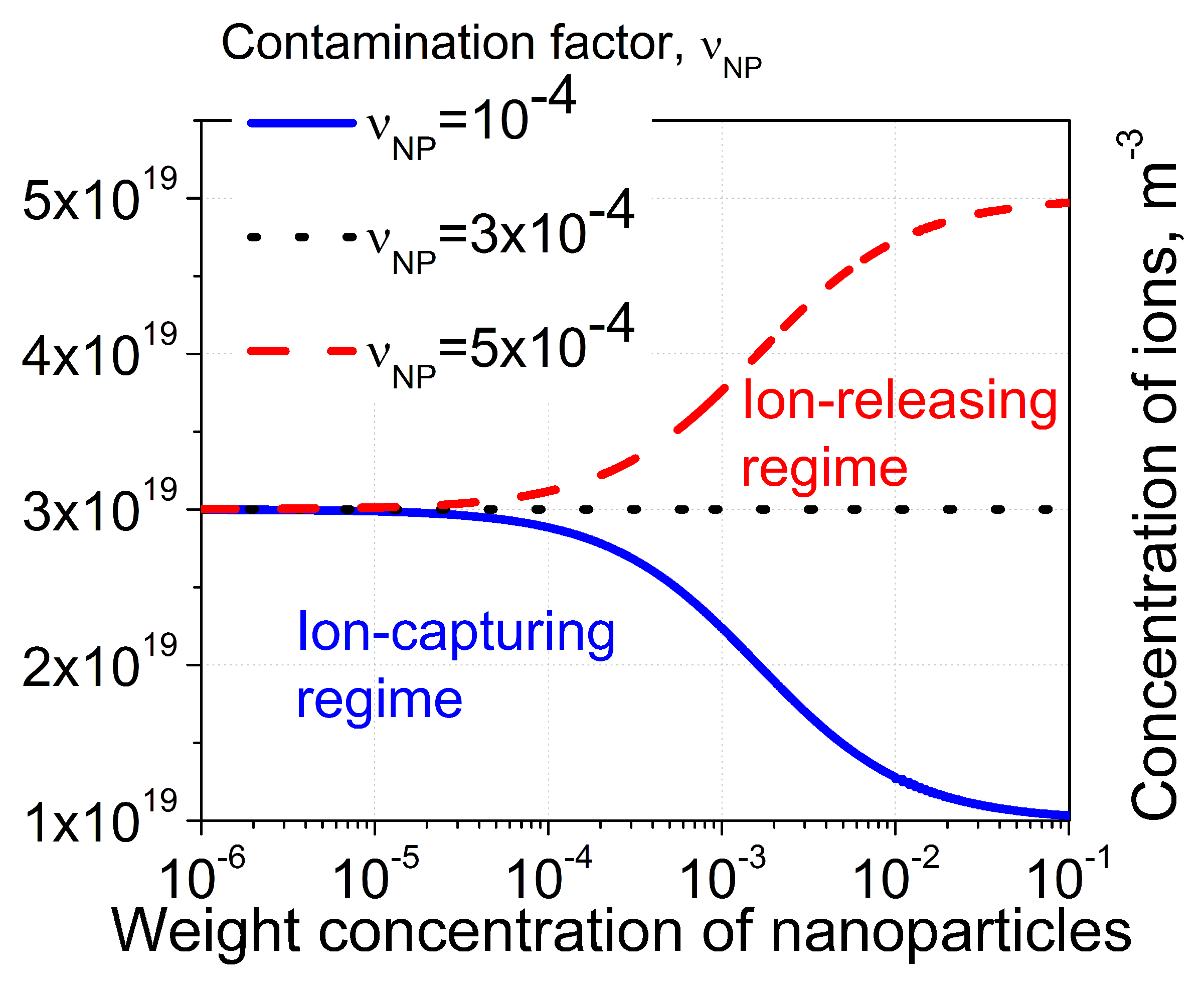
In the majority of the reported experimental studies, steady-state measurements are performed (). In regard to the concentration of mobile ions in liquid crystals doped with nanomaterials, an analysis of possible regimes achieved in such systems was done in paper [61]. Three regimes, namely, the ion-capturing regime (solid curve), ion-releasing regime (dashed curve), and no change regime (dotted curve), are shown in Figure 2, where the concentration of mobile ions in liquid crystals is plotted as a function of the weight concentration of nanoparticles.
In the case of ion capturing regime, the concentration of mobile ions in liquid crystals decreases as the weight concentration of nanodopants goes up (). This regime is achieved if . The ion releasing regime is characterized by the increase in the concentration of mobile ions with an increase in the weight concentration of nanoparticles (). It is observed if . The concentration of mobile ions in liquid crystals doped with nanoparticles does not change if . Switching between these three different regimes can be achieved by changing the level of ionic contamination of nanomaterials , the ionic purity of liquid crystals (an initial concentration of mobile ions ), and by varying materials used in experiments (constant ) as shown in Table 1 (this table is created using similar table published in paper [61]).
2.4. Temperature-Induced Effects
Constants describing ion-capturing () and ion-releasing () processes in liquid crystals doped with nanomaterials are temperature-dependent [65,66]. By approximating this temperature dependence through Equations (8) and (9), temperature-induced ionic effects in liquid crystals doped with nanoparticles can be analyzed [65,66].
where is the adsorption activation energy; is the desorption activation energy; and are pre-exponential factors; ; and is temperature [65,66].
By applying Equations (8) and (9), constant can be written as Expression (10):
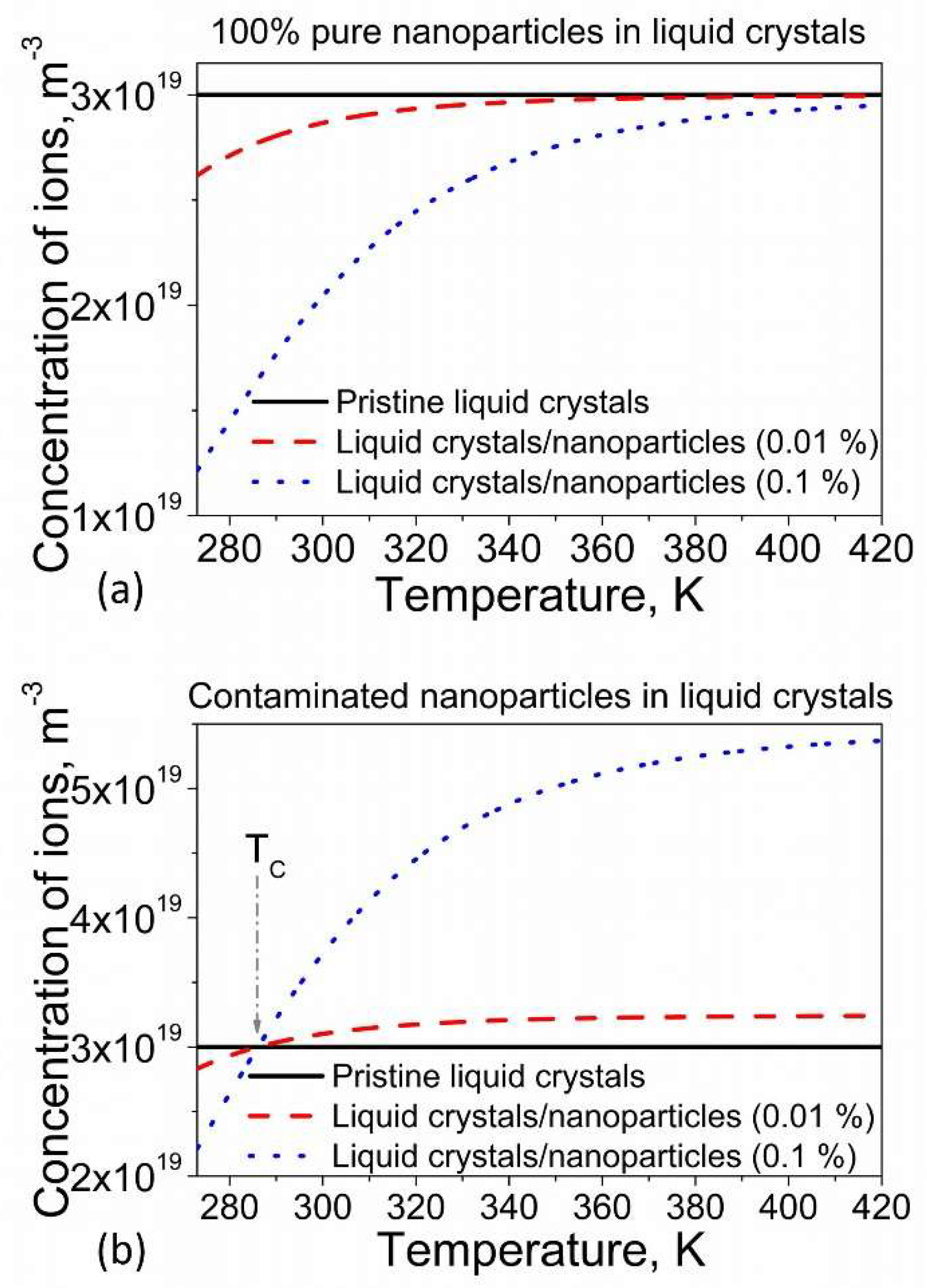
Temperature dependence (Equation (10)) can result in temperature-induced release of ions experimentally observed in liquid crystals doped with nanoparticles [65]. Typical dependence calculated using Equations (1), (2), (10) is shown in Figure 3.
Figure 3a illustrates the so-called temperature-induced release of ions in liquid crystals doped with nanoparticles. The concentration of mobile ions in liquid crystals doped with nanomaterials increases as its temperature goes up. In the case of 100% pure nanodopants, this increase saturates at higher temperatures, approaching an initial concentration of ions in liquid crystals (this means that at a high enough temperature, nanoparticles lose their ion-capturing properties, see Figure 3a). It should be stressed that if 100% pure nanoparticles are mixed with liquid crystals, the concentration of mobile ions in such systems is always less or equal to the initial concentration: . In other words, the ion-capturing regime is observed (and it approaches the “no change” regime () at elevated temperatures, Figure 3a). On the contrary, the dependence of liquid crystals, doped with contaminated nanomaterials, exhibits some interesting features (Figure 3b). There are two distinct regions (Figure 3b). At temperatures , the concentration of mobile ions in liquid crystals doped with nanomaterials is less than the concentration of ions in pristine (without nanodopants) liquid crystals (), which corresponds to the ion-capturing regime. Above this temperature (), an opposite inequality holds true , which corresponds to the ion-releasing regime (Figure 3b). No change regime corresponds to temperature . Temperature can be found using Equation (11) [65]:
Thus, a temperature-induced switching between ion-capturing and ion-releasing regimes can be achieved in liquid crystals doped with contaminated nanomaterials [65].
Temperature-induced release of ions is observed in systems characterized by positive values of their parameter, . Interestingly, liquid crystals doped with nanoparticles and characterized by negative values of this parameter () should exhibit an opposite effect, namely, temperature-induced capturing of ions [66]. This unusual effect was analyzed in paper [66].
3. Case Studies: A Brief Survey
The proposed model of contaminated nanoparticles in liquid crystals [61] was successfully applied to existing experimental data [62,71]. Table 2 provides a summary of the observed experimental effects and physical parameters used in calculations to achieve a very good agreement between the model and experiments.
4. Case Study: Non-Monotonous Dependence
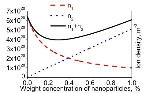
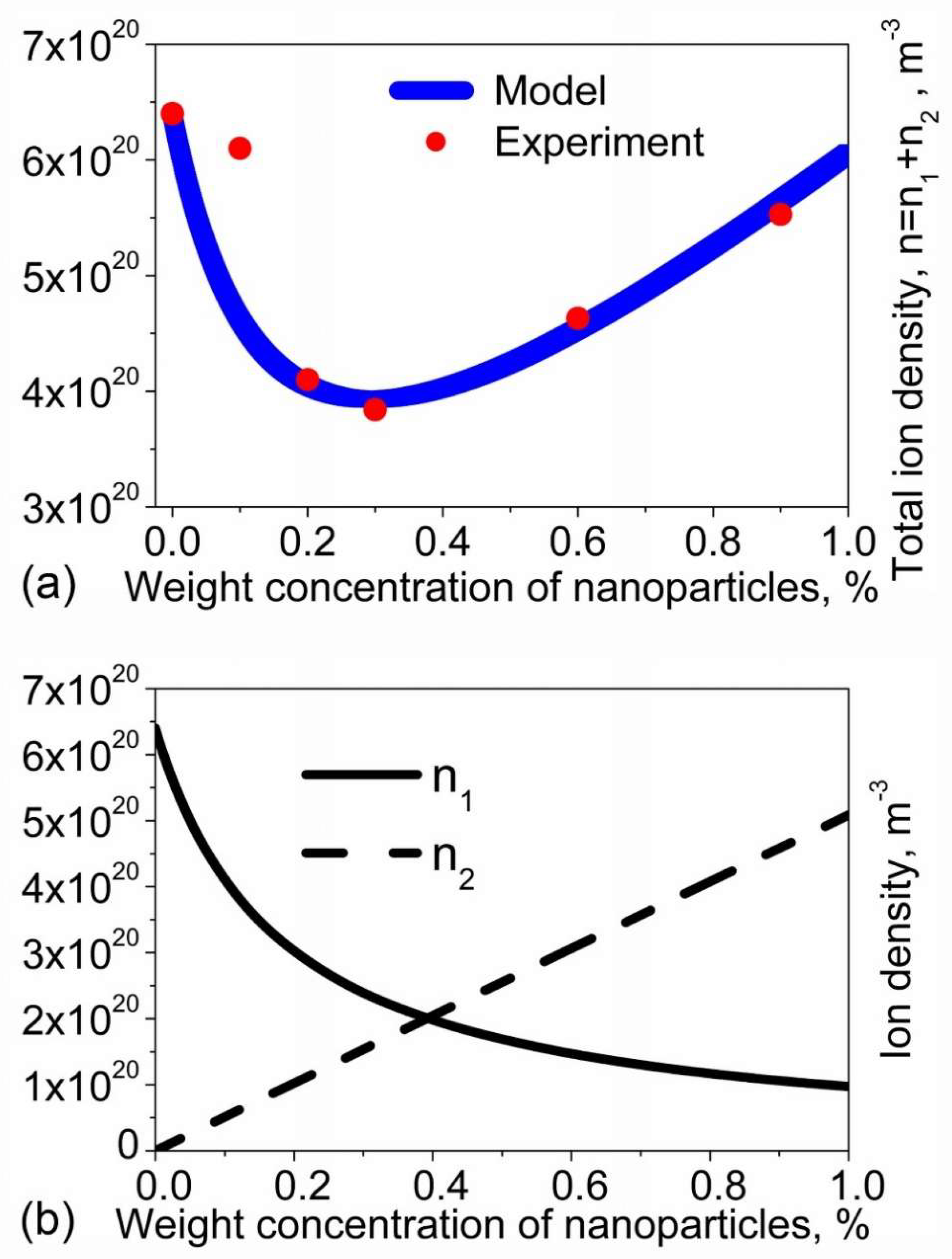
As was already mentioned, the proposed model of contaminated nanomaterials in liquid crystals can also account for the case of several types of dominant ions, and (Equations (3) and (4)). In this section, these equations are applied to analyze reported experimental data for nematic liquid crystals (E7) doped with silica nanoparticles (SN R812) [80]. In paper [80], the measured ion density exhibited non-monotonous dependence on the concentration of nanoparticles. Upon increasing the concentration of silica nanoparticles in liquid crystals, the measured ion density decreased and reached its minimum value. Further increase in the concentration of nanoparticles resulted in the increase in the ion density. This non-monotonous behavior can be modeled using Equations (3) and (4). The results are shown in Figure 4.
A non-monotonous behavior , shown in Figure 4a, can be explained in the following way. Pristine liquid crystals are characterized by a single type of dominant ions . Silica nanoparticles, prior to dispersing them in liquid crystals, are contaminated with ions . Once silica nanoparticles are dispersed in liquid crystals, ions are adsorbed on the surface of nanoparticles. As a result, the concentration of ions decreases with the increase in the concentration of nanoparticles (Figure 4b, solid curve). At the same time, silica nanoparticles can release ions into the liquid crystal bulk. As a result, the concentration of these ions in liquid crystals increases as the concentration of nanoparticles goes up (Figure 4b, dashed curve). The combined result of ion-capturing effects () and ion-releasing effect () leads to the observed non-monotonous behavior (Figure 4a).
Another very interesting result reported in paper [80] is the effect of a high-voltage pulse treatment on the concentration of ions in liquid crystals doped with silica nanoparticles. The model discussed in this review cannot model the kinetics of high voltage-induced effects in liquid crystals doped with nanoparticles. Indeed, in Equations (3) and (4), material-dependent coefficients are considered constant. However, once the treatment of liquid crystal/nanoparticle system with high voltage is completed, Equations (3) and (4) can still be used. It can be reasonably assumed that the applied high electric field can change some material parameters of liquid crystals doped with nanoparticles ( and ). In addition, the applied electric field can change the contamination factor of nanoparticles . Additional studies are needed to understand physical and chemical mechanisms involved in these processes. By applying Equations (3) and (4), a good agreement between reported experimental data [80] and the proposed model of contaminated nanomaterials can be achieved (Figure 5).
5. Conclusions
Existing experimental results (Table 2) unambiguously show that nanomaterials in liquid crystals can affect the concentration of ions in different ways. The dispersion of nanomaterials in liquid crystals can result in the ion capturing effect, ion releasing effect, or the combination of them. Therefore, nanomaterials in liquid crystals should be considered as new sources of ions or as ion trapping objects. The model of contaminated nanomaterials in liquid crystals reviewed in this paper can predict both ion capturing and ion releasing (or ion generation) regimes (Figure 1, Figure 2 and Figure 3). Moreover, it also predicts a new effect, namely temperature-induced ion-capturing effect [66]. This model is in a very good agreement with reported experimental data (Table 2).
So far, the origin of ionic contamination of nanomaterials is poorly understood. In many practical cases, this contamination can originate from particular chemical procedures utilized during chemical synthesis of nano-objects. Ionic contaminants can also originate from the contact of nanomaterials with environment and due to external factors, such as ionizing radiation, high electric fields, excessive heating, and chemical degradation. The aforementioned possible causes of ionic contamination of nanomaterials are caused by external factors and, therefore, are extrinsic in nature. This type of ionic contamination is typically characterized by relatively low values of the contamination factor. It can be reduced or even eliminated by improving physical/chemical procedures used to produce, storage, and handle nanomaterials. There is also an intrinsic source of ionic contamination of nanoparticles. For example, self-dissociating nanomaterials can generate ions because of their chemical/physical composition. In this case, the contamination factor of nanoparticles is relatively high, and cannot be reduced by improving the purification procedure. Interestingly, both types of ionic contamination (intrinsic and extrinsic) can be successfully analyzed by the model reviewed in this paper. Further studies are needed to understand mechanisms of ionic contamination of nanomaterials and their impact on the properties of liquid crystals.
Acknowledgments
The author would like to acknowledge the support provided by the UCCS BioFrontiers Center at the University of Colorado.
Conflicts of Interest
The author declares no conflict of interest.
Abbreviations
The following abbreviations are used in this manuscript:
| MDPI | Multidisciplinary Digital Publishing Institute |
| DOAJ | Directory of open access journals |
| LCD | Liquid crystal display |
References
- Yang, D.K.; Wu, S.T. Liquid Crystal Devices; John Wiley & Sons: Hoboken, NJ, USA, 2006; pp. 1–378. [Google Scholar]
- Chigrinov, V.G. Liquid Crystal Devices: Physics and Applications; Artech House: Boston, MA, USA, 1999; pp. 1–360. [Google Scholar]
- Abdulhalim, I. Non-display bio-optic applications of liquid crystals. Liq. Cryst. Today 2011, 20, 44–60. [Google Scholar] [CrossRef]
- De Sio, L.; Roberts, D.E.; Liao, Z.; Hwang, J.; Tabiryan, N.; Steeves, D.M.; Kimball, B.R. Beam shaping diffractive wave plates. Appl. Opt. 2018, 57, A118–A121. [Google Scholar] [CrossRef] [PubMed]
- Lin, Y.-H.; Wang, Y.-J.; Reshetnyak, V. Liquid crystal lenses with tunable focal length. Liq. Cryst. Rev. 2017, 5, 111–143. [Google Scholar] [CrossRef]
- Geis, M.W.; Bos, P.J.; Liberman, V.; Rothschild, M. Broadband optical switch based on liquid crystal dynamic scattering. Opt. Express 2016, 24, 13812–13823. [Google Scholar] [CrossRef] [PubMed]
- Naemura, S. Electrical properties of liquid crystal materials for display applications. Mater. Res. Soc. Symp. Proc. 1999, 559, 263–274. [Google Scholar] [CrossRef]
- Neyts, K.; Beunis, F. Handbook of Liquid Crystals: Physical Properties and Phase Behavior of Liquid Crystals; Wiley-VCH: Weinheim, Germany, 2014; pp. 357–382. [Google Scholar]
- Korniychuk, P.P.; Gabovich, A.M.; Singer, K.; Voitenko, A.I.; Reznikov, Y.A. Transient and steady electric currents through a liquid crystal cell. Liq. Cryst. 2010, 37, 1171–1181. [Google Scholar] [CrossRef]
- Blinov, L.M. Structure and Properties of Liquid Crystals; Springer: New York, NY, USA, 2010. [Google Scholar]
- Chang, R.; Richardson, J.M. The anisotropic electrical conductivity of MBBA containing tetrabutyl-ammonium tetraphenyl-boride. Mol. Cryst. Liq. Cryst. 1973, 28, 189–200. [Google Scholar] [CrossRef]
- Barnik, M.I.; Blinov, L.M.; Grebenkin, M.F.; Pikin, S.A.; Chigrinov, V.G. Electrohydrodynamic instability in nematic liquid crystals. Sov. Phys. JETP 1976, 42, 550–553. [Google Scholar]
- Naemura, S.; Sawada, A. Ionic conduction in nematic and smectic liquid crystals. Mol. Cryst. Liq. Cryst. 2003, 400, 79–96. [Google Scholar] [CrossRef]
- Hung, H.Y.; Lu, C.W.; Lee, C.Y.; Hsu, C.S.; Hsieh, Y.Z. Analysis of metal ion impurities in liquid crystals using high resolution inductively coupled plasma mass spectrometry. Anal. Methods 2012, 4, 3631–3637. [Google Scholar] [CrossRef]
- Murakami, S.; Naito, H. Electrode and interface polarizations in nematic liquid crystal cells. Jpn. J. Appl. Phys. 1997, 36, 2222–2225. [Google Scholar] [CrossRef]
- Mizusaki, M.; Enomoto, S.; Hara, Y. Generation mechanism of residual direct current voltage for liquid crystal cells with polymer layers produced from monomers. Liq. Cryst. 2017, 44, 609–617. [Google Scholar] [CrossRef]
- Kravchuk, R.; Koval’chuk, O.; Yaroshchuk, O. Filling initiated processes in liquid crystal cell. Mol. Cryst. Liq. Cryst. 2002, 384, 111–119. [Google Scholar] [CrossRef]
- Garbovskiy, Y. Time dependent electrical properties of liquid crystal cells: Unravelling the origin of ion generation. Liq. Cryst. 2018. [Google Scholar] [CrossRef]
- Chieu, T.C.; Yang, K.H. Transport properties of ions in ferroelectric liquid crystal cells. Jpn. J. Appl. Phys. 1989, 28, 2240–2246. [Google Scholar] [CrossRef]
- Murakami, S.; Naito, H. Charge injection and generation in nematic liquid crystal cells. Jpn. J. Appl. Phys. 1997, 36, 773–776. [Google Scholar] [CrossRef]
- Naemura, S.; Sawada, A. Ion Generation in Liquid Crystals under Electric Field. Mol. Cryst. Liq. Cryst. 2000, 346, 155–168. [Google Scholar] [CrossRef]
- De Vleeschouwer, H.; Verschueren, A.; Bougrioua, F.; van Asselt, R.; Alexander, E.; Vermael, S.; Neyts, K.; Pauwels, H. Long-term ion transport in nematic liquid crystal displays. Jpn. J. Appl. Phys. 2001, 40, 3272–3276. [Google Scholar] [CrossRef]
- Kovalchuk, A.V.; Lavrentovich, O.D.; Linev, V.A. Electrical conductivity of γ-irradiated cholesteric liquid crystals. Sov. Tech. Phys. Lett. 1988, 14, 381–382. [Google Scholar]
- Naito, H.; Yoshida, K.; Okuda, M.; Sugimura, A. Transient Current Study of Ultraviolet-Light-Soaked States in n-Pentyl-p-n-Cyanobiphenyl. Jpn. J. Appl. Phys. 1994, 33, 5890–5891. [Google Scholar] [CrossRef]
- Barret, S.; Gaspard, F.; Herino, R.; Mondon, F. Dynamic scattering in nematic liquid crystals under dc conditions. I. Basic electrochemical analysis. J. Appl. Phys. 1976, 47, 2375–2377. [Google Scholar] [CrossRef]
- Barret, S.; Gaspard, F.; Herino, R.; Mondon, F. Dynamic scattering in nematic liquid crystals under DC conditions. II. Monitoring of electrode processes and lifetime investigation. J. Appl. Phys. 1976, 47, 2378–2381. [Google Scholar] [CrossRef]
- Lim, H.S.; Margerum, J.D.; Graube, A. Electrochemical properties of dopants and the DC dynamic scattering of a nematic liquid crystal. J. Electrochem. Soc. Sol. State Sci. Technol. 1977, 124, 1389–1394. [Google Scholar]
- Rahman, M.; Lee, W. Scientific duo of carbon nanotubes and nematic liquid crystals. J. Phys. D Appl. Phys. 2009, 42, 063001. [Google Scholar] [CrossRef]
- Garbovskiy, Y.; Glushchenko, A. Liquid crystalline colloids of nanoparticles: Preparation, properties, and applications. Sol. State Phys. 2011, 62, 1–74. [Google Scholar]
- Garbovskiy, Y.; Zribi, O.; Glushchenko, A. Emerging Applications of Ferroelectric Nanoparticles in Materials Technologies, Biology and Medicine. In Advances in Ferroelectrics; Peláiz-Barranco, A., Ed.; InTech: Rijeka, Croatia, 2012. [Google Scholar] [Green Version]
- Mirzaei, J.; Reznikov, M.; Hegmann, T. Quantum dots as liquid crystal dopants. J. Mater. Chem. 2012, 22, 22350–22365. [Google Scholar] [CrossRef]
- Stamatoiu, O.; Mirzaei, J.; Feng, X.; Hegmann, T. Nanoparticles in liquid crystals and liquid crystalline nanoparticles. Top. Curr. Chem. 2012, 318, 331–394. [Google Scholar] [PubMed]
- Blanc, C.; Coursault, D.; Lacaze, E. Ordering nano- and microparticles assemblies with liquid crystals. Liq. Cryst. Rev. 2013, 1, 83–109. [Google Scholar] [CrossRef]
- Kumar, S. Discotic liquid crystal-nanoparticle hybrid systems. NPG Asia Mater. 2014, 6, e82. [Google Scholar] [CrossRef]
- Urbanski, M. On the impact of nanoparticle doping on the electro-optic response of nematic hosts. Liq. Cryst. Today 2015, 24, 102–115. [Google Scholar] [CrossRef]
- Klimusheva, G.; Mirnaya, T.; Garbovskiy, Y. Versatile Nonlinear-Optical Materials Based on Mesomorphic Metal Alkanoates: Design, Properties, and Applications. Liq. Cryst. Rev. 2015, 3, 28–57. [Google Scholar] [CrossRef]
- Yadav, S.P.; Singh, S. Carbon nanotube dispersion in nematic liquid crystals: An overview. Prog. Mater. Sci. 2016, 80, 38–76. [Google Scholar] [CrossRef]
- Mertelj, A.; Lisjak, D. Ferromagnetic nematic liquid crystals. Liq. Cryst. Rev. 2017, 5, 1–33. [Google Scholar] [CrossRef]
- Quan, L. (Ed.) Nanoscience with Liquid Crystals; Springer: Cham, Switzerland, 2014; p. 420. [Google Scholar]
- Lagerwall, J.P.F.; Scalia, G. Liquid Crystals with Nano and Microparticles; World Scientific Publishing Co.: Singapore, 2016; pp. 461–920. [Google Scholar]
- Garbovskiy, Y.; Glushchenko, I. Nano-Objects and Ions in Liquid Crystals: Ion Trapping Effect and Related Phenomena. Crystals 2015, 5, 501–533. [Google Scholar] [CrossRef] [Green Version]
- Jian, B.R.; Tang, C.Y.; Lee, W. Temperature-dependent electrical properties of dilute suspensions of carbon nanotubes in nematic liquid crystals. Carbon 2011, 49, 910–914. [Google Scholar] [CrossRef]
- Tomylko, S.; Yaroshchuk, O.; Kovalchuk, O.; Maschke, U.; Yamaguchi, R. Dielectric properties of nematic liquid crystal modified with diamond nanoparticles. Ukrainian J. Phys. 2012, 57, 239–243. [Google Scholar]
- Wu, P.C.; Lisetski, L.N.; Lee, W. Suppressed ionic effect and low-frequency texture transitions in a cholesteric liquid crystal doped with graphene nanoplatelets. Opt. Express 2015, 23, 11195–11204. [Google Scholar] [CrossRef] [PubMed]
- Shukla, R.K.; Feng, X.; Umadevi, S.; Hegmann, T.; Haase, W. Influence of different amount of functionalized bulky gold nanorods dopant on the electrooptical, dielectric and optical properties of the FLC host. Chem. Phys. Lett. 2014, 599, 80–85. [Google Scholar] [CrossRef]
- Podgornov, F.V.; Wipf, R.; Stühn, B.; Ryzhkova, A.V.; Haase, W. Low-frequency relaxation modes in ferroelectric liquid crystal/gold nanoparticle dispersion: Impact of nanoparticle shape. Liq. Cryst. 2016, 43, 1536–1547. [Google Scholar] [CrossRef]
- Urbanski, M.; Lagerwall, J.P.F. Why organically functionalized nanoparticles increase the electrical conductivity of nematic liquid crystal dispersions. J. Mater. Chem. C 2017, 5, 8802–8809. [Google Scholar] [CrossRef]
- Podgornov, F.V.; Gavrilyak, M.; Karaawi, A.; Boronin, V.; Haase, W. Mechanism of electrooptic switching time enhancement in ferroelectric liquid crystal/gold nanoparticles dispersion. Liq. Cryst. 2018. [Google Scholar] [CrossRef]
- Tang, C.Y.; Huang, S.M.; Lee, W. Electrical properties of nematic liquid crystals doped with anatase TiO2 nanoparticles. J. Phys. D Appl. Phys. 2011, 44, 355102. [Google Scholar] [CrossRef]
- Chandran, A.; Prakash, J.; Gangwar, J.; Joshi, T.; Kumar Srivastava, A.; Haranath, D.; Biradar Ashok, M. Low-voltage electro-optical memory device based on NiO nanorods dispersed in a ferroelectric liquid crystal. RSC Adv. 2016, 6, 53873–53881. [Google Scholar] [CrossRef] [Green Version]
- Shcherbinin, D.P.; Konshina, E.A. Impact of titanium dioxide nanoparticles on purification and contamination of nematic liquid crystals. Beilstein J. Nanotechnol. 2017, 8, 2766–2770. [Google Scholar] [CrossRef] [PubMed] [Green Version]
- Kovalchuk, O.V.; Studenyak, I.P.; Izai, V.Y.; Rubak, S.O.; Pogodin, A.I.; Kopcansky, P.; Timko, M.; Gdovinova, V.; Mariano, J.; Kovalchuk, T.M. Saturation effect for dependence of the electrical conductivity of planar oriented liquid crystal 6CB on the concentration of Cu7PS6 nanoparticles. Semicond. Phys. Quantum Electron. Optoelectron. 2017, 20, 437–441. [Google Scholar] [CrossRef]
- Shcherbinin, D.P.; Konshina, E.A. Ionic impurities in nematic liquid crystal doped with quantum dots CdSe/ZnS. Liq. Cryst. 2017, 44, 648–655. [Google Scholar] [CrossRef]
- Konshina, E.; Shcherbinin, D. Comparison of the properties of nematic liquid crystals doped with TiO2 and CdSe/ZnS nanoparticles. J. Mol. Liq. 2017. [Google Scholar] [CrossRef]
- Shukla, R.K.; Liebig, C.M.; Evans, D.R.; Haase, W. Electro-optical behaviour and dielectric dynamics of harvested ferroelectric LiNbO3 nanoparticle-doped ferroelectric liquid crystal nanocolloids. RSC Adv. 2014, 4, 18529–18536. [Google Scholar] [CrossRef]
- Basu, R.; Garvey, A. Effects of ferroelectric nanoparticles on ion transport in a liquid crystal. Appl. Phys. Lett. 2014, 105, 151905. [Google Scholar] [CrossRef]
- Garbovskiy, Y.; Glushchenko, I. Ion trapping by means of ferroelectric nanoparticles, and the quantification of this process in liquid crystals. Appl. Phys. Lett. 2015, 107, 041106. [Google Scholar] [CrossRef]
- Hsiao, Y.G.; Huang, S.M.; Yeh, E.R.; Lee, W. Temperature-dependent electrical and dielectric properties of nematic liquid crystals doped with ferroelectric particles. Displays 2016, 44, 61–65. [Google Scholar] [CrossRef]
- Al-Zangana, S.; Turner, M.; Dierking, I. A comparison between size dependent paraelectric and ferroelectric BaTiO3 nanoparticle doped nematic and ferroelectric liquid crystals. J. Appl. Phys. 2017, 121, 085105. [Google Scholar] [CrossRef]
- Kumar, P.; Debnath, S.; Rao, N.V.S.; Sinha, A. Nanodoping: A route for enhancing electro-optic performance of bent core nematic system. J. Phys. Condens. Matter. 2018, 30, 095101. [Google Scholar] [CrossRef] [PubMed]
- Garbovskiy, Y. Switching between purification and contamination regimes governed by the ionic purity of nanoparticles dispersed in liquid crystals. Appl. Phys. Lett. 2016, 108, 121104. [Google Scholar] [CrossRef]
- Garbovskiy, Y. Electrical properties of liquid crystal nano-colloids analysed from perspectives of the ionic purity of nano-dopants. Liq. Cryst. 2016, 43, 648–653. [Google Scholar] [CrossRef]
- Garbovskiy, Y. Impact of contaminated nanoparticles on the non-monotonous change in the concentration of mobile ions in liquid crystals. Liq. Cryst. 2016, 43, 664–670. [Google Scholar] [CrossRef]
- Garbovskiy, Y. Ions and size effects in nanoparticle/liquid crystal colloids sandwiched between two substrates. The case of two types of fully ionized species. Chem. Phys. Lett. 2017, 679, 77–85. [Google Scholar] [CrossRef]
- Garbovskiy, Y. Nanoparticle enabled thermal control of ions in liquid crystals. Liq. Cryst. 2017, 44, 948–955. [Google Scholar] [CrossRef]
- Garbovskiy, Y. Ions in liquid crystals doped with nanoparticles: Conventional and counterintuitive temperature effects. Liq. Cryst. 2017, 44, 1402–1408. [Google Scholar] [CrossRef]
- Garbovskiy, Y. The purification and contamination of liquid crystals by means of nanoparticles. The case of weakly ionized species. Chem. Phys. Lett. 2016, 658, 331–335. [Google Scholar] [CrossRef]
- Garbovskiy, Y. Ion capturing/ion releasing films and nanoparticles in liquid crystal devices. Appl. Phys. Lett. 2017, 110, 041103. [Google Scholar] [CrossRef]
- Garbovskiy, Y. Kinetics of Ion-Capturing/Ion-Releasing Processes in Liquid Crystal Devices Utilizing Contaminated Nanoparticles and Alignment Films. Nanomaterials 2018, 8, 59. [Google Scholar] [CrossRef] [PubMed]
- Garbovskiy, Y. Adsorption of ions onto nanosolids dispersed in liquid crystals: Towards understanding the ion trapping effect in nanocolloids. Chem. Phys. Lett. 2016, 651, 144–147. [Google Scholar] [CrossRef]
- Garbovskiy, Y. Nanoparticle—Enabled Ion Trapping and Ion Generation in Liquid Crystals. Adv. Condens. Matter Phys. 2018, 2018, 8914891. [Google Scholar]
- Garbovskiy, Y. Adsorption/desorption of ions in liquid crystal nano-colloids: The applicability of the Langmuir isotherm, impact of high electric fields, and effects of the nanoparticle’s size. Liq. Cryst. 2016, 43, 853–860. [Google Scholar] [CrossRef]
- Barbero, G.; Evangelista, L.R. Adsorption Phenomena and Anchoring Energy in Nematic Liquid Crystals; Taylor & Francis: Boca Raton, FL, USA, 2006. [Google Scholar]
- Steffen, V.; Cardozo-Filho, L.; Silva, E.A.; Evangelista, L.R.; Guirardello, R.; Mafra, M.R. Equilibrium modeling of ion adsorption based on Poisson–Boltzmann equation. Colloids Surf. A Physicochem. Eng. Asp. 2015, 468, 159–166. [Google Scholar] [CrossRef]
- Batalioto, F.; Figueiredo Neto, A.M.; Barbero, G. Ion trapping on silica nanoparticles: Effect on the ζ-potential. J. Appl. Phys. 2017, 122, 164303. [Google Scholar] [CrossRef]
- Steffen, V.; Silva, E.A.; Evangelista, L.R.; Cardozo-Filho, L. Debya-Huckel approximation for simplification of ions adsorption equilibrium model based on Poisson-Boltzmann equation. Surf. Interfaces 2018, 10, 144–148. [Google Scholar] [CrossRef]
- Nanowerk Spotlight. Ionic Purity of Nanoparticles Is Key to Switching between Purification and Contamination Regimes in Liquid Crystal Devices. Available online: https://www.nanowerk.com/spotlight/spotid=42995.php (accessed on 22 June 2018).
- Nanowerk Spotlight. A Nanotechnology Approach to Purifying Liquid Crystals. Available online: https://www.nanowerk.com/spotlight/spotid=45659.php (accessed on 22 June 2018).
- Wu, P.W.; Lee, W. Phase and dielectric behaviors of a polymorphic liquid crystal doped with graphene nanoplatelets. Appl. Phys. Lett. 2013, 102, 162904. [Google Scholar] [CrossRef]
- Liao, S.-W.; Hsieh, C.-T.; Kuo, C.-C.; Huang, C.-Y. Voltage-assisted ion reduction in liquid crystal-silica nanoparticle dispersions. Appl. Phys. Lett. 2012, 101, 161906. [Google Scholar] [CrossRef]
Figure 1.
(a) The volume concentration of mobile ions versus time calculated using different values of the weight concentration of nanoparticles and their contamination factor ( (dotted, dashed, and dotted–dashed curves); (solid curve); (dashed–dotted–dotted, short-dashed, and short-dotted curves). The radius of nanoparticles is 5 nm. (b) The time constant as a function of the weight concentration of nanoparticles calculated at different values of the nanoparticle radius ( (dashed–dotted curve); (dashed curve); (dotted curve); (solid curve)). Other parameters used in simulations: , , , , . Reproduced from [69], under the Creative Commons Attribution License.

Figure 2.
The volume concentration of mobile ions in liquid crystals versus the weight concentration of nanoparticles calculated at different values of their contamination factor ( (solid curve); (dotted curve); and (dashed curve)). The radius of nanoparticles is 10 nm. Other parameters used in simulations: , , , . This figure is also posted on Nanowerk Spotlight [77].

Figure 3.
The volume concentration of mobile ions in liquid crystals doped with nanoparticles plotted as a function of temperature for two cases: (a) 100% pure nanoparticles in liquid crystals; and (b) contaminated nanoparticles in liquid crystals. Physical parameters used in simulations: (a) and (b); ; eV; ; ; . The radius of nanoparticles is 10 nm. The weight concentration of nanoparticles is 0.01% (dashed curve) and 0.1% (dotted curve). This figure is also posted on Nanowerk Spotlight [78].

Figure 4.
The total ion density of mobile ions in liquid crystals doped with silica nanoparticles as a function of their weight concentration : (a) ; (b) (solid curve) and (dashed curve). Reported experimental data points [80] are represented by circles. A blue curve shows theoretical fit according to Equations (3) and (4). Fitting parameters: ; ; ; ; ; ; ; ; ; .

Figure 5.
The total ion density of mobile ions in liquid crystals doped with silica nanoparticles as a function of their weight concentration : (a) ; (b) (solid curve) and (dashed curve). Reported experimental data points [80] are represented by circles. A blue curve shows theoretical fit according to Equations (3) and (4). Fitting parameters: ; ; ; ; ; ; ; ; ; .


Table 1.
Ion-capturing, ion-releasing, and no change regimes in liquid crystals doped with contaminated nanoparticles [61].
Table 1.
Ion-capturing, ion-releasing, and no change regimes in liquid crystals doped with contaminated nanoparticles [61].
| Physical Parameters | Ion-Capturing Regime | No Change Regime | Ion-Releasing Regime |
|---|---|---|---|
| Contamination level of nanomaterials, | |||
| Initial concentration of ions in liquid crystals, | |||
| Constant, |
Table 2.
Case studies: reported experimental data and physical parameters of the model.
| Materials | Reported Effects | Physical Parameters |
|---|---|---|
| Anatase () nanoparticles in nematic liquid crystals (E44) | Ion-capturing effect [49] | m3; ; m−2; nm; [62] |
| Carbon nanotubes (CNT) in nematic liquid crystals (E7) | Ion-capturing effect [42] | m3; ; m−2; nm; nm; [62] |
| Diamond nanoparticles in nematic liquid crystals (E7) | Ion-capturing effect [43] | m3; ; m−2; nm; [62] |
| Diamond nanoparticles in nematic liquid crystals (E7) | Ion-releasing effect [43] | m3; ; m−2; nm; [62] |
| Graphene nano-flakes (GNF) in nematic liquid crystals (8OCB) | Ion-capturing effect [79] | m3; ; m−2; nm; nm; [62] |
| Ferroelectric nanoparticles () in liquid crystals | Ion-capturing effect [55] | m3; ; m−2; nm; [62] |
| Ferroelectric particles () in nematic liquid crystals | Ion-capturing effect [57] | m3; ; m−2; nm; [62] |
| Ferroelectric nanoparticles () in nematic liquid crystals (E44) | Temperature-induced release of ions [58] | ; m3; eV; m−2; nm; [65] |
| nanoparticles in nematic liquid crystals (ZhK1282) | Ion-releasing effect [51] | ; m3; m−2; nm; [71] |
| nanoparticles in nematic liquid crystals (ZhK1282) | Ion-capturing effect [51] | ; m3; m−2; nm; [71] |
| core/shell nanoparticles in nematic liquid crystals (ZhK1289) | Ion-releasing effect [53] | ; m3; m−2; nm; [71] |
| nanoparticles in nematic liquid crystals (6CB) | Ion releasing effect [52] | ; m3; m−2; nm; [71] |
© 2018 by the author. Licensee MDPI, Basel, Switzerland. This article is an open access article distributed under the terms and conditions of the Creative Commons Attribution (CC BY) license (http://creativecommons.org/licenses/by/4.0/).
Share and Cite
MDPI and ACS Style
Garbovskiy, Y. Nanomaterials in Liquid Crystals as Ion-Generating and Ion-Capturing Objects. Crystals 2018, 8, 264. https://0-doi-org.brum.beds.ac.uk/10.3390/cryst8070264
AMA Style
Garbovskiy Y. Nanomaterials in Liquid Crystals as Ion-Generating and Ion-Capturing Objects. Crystals. 2018; 8(7):264. https://0-doi-org.brum.beds.ac.uk/10.3390/cryst8070264
Chicago/Turabian StyleGarbovskiy, Yuriy. 2018. "Nanomaterials in Liquid Crystals as Ion-Generating and Ion-Capturing Objects" Crystals 8, no. 7: 264. https://0-doi-org.brum.beds.ac.uk/10.3390/cryst8070264
Note that from the first issue of 2016, this journal uses article numbers instead of page numbers. See further details here.