Ion Irradiation for Planar Patterning of Magnetic Materials


1
Department of Electronics, Nagoya University Furo-cho, Chikusa-ku, Nagoya 464-8603, Japan
2
Institute of Materials and Systems for Sustainability, Nagoya University Furo-cho, Chikusa-ku, Nagoya 464-8603, Japan
*
Author to whom correspondence should be addressed.
Crystals 2019, 9(1), 27; https://0-doi-org.brum.beds.ac.uk/10.3390/cryst9010027
Submission received: 26 November 2018
/
Revised: 25 December 2018
/
Accepted: 26 December 2018
/
Published: 4 January 2019
(This article belongs to the Special Issue Spin-dependent Optical, Plasmonic, Confinement and High-frequency Phenomena and Applications—Mini-symposium, ETOPIM11)
Abstract
:Kr+ ion dose dependence of the magnetic properties of MnGa films and the fabrication of planar-patterned MnGa films by the local ion irradiation technique were reviewed. The magnetization and perpendicular anisotropy of the MnGa vanished at an ion dose of 1 × 10¹⁴ ions/cm2 due to the phase change of the MnGa from ferromagnetic L10 to paramagnetic A1 phase. The average switching field Hsw of the planar-patterned MnGa increased with decreasing the bit size, implying low bit edge damage in the patterned MnGa, whereas a rather large switching field distribution (SFD) of 25% was confirmed for a bit size of ~40 nm. Time resolved magneto-optical Kerr effect measurements revealed that as-prepared MnGa exhibits an effective anisotropy field Hkeff = 20 kOe, its distribution ΔHkeff = 200 Oe, and Gilbert damping α = 0.008. The ion-irradiated MnGa films exhibited larger Hkeff = 22–23 kOe than that of the MnGa before the ion dose. Thus, ion irradiation does not decrease the perpendicular anisotropy, which suggests a small bit edge in the patterned MnGa. ΔHkeff increased from 0.2 kOe to 3 kOe, whereas the length of disorder in the film ξ decreased from 10 nm to 3 nm by ion irradiation.
1. Introduction
The nanofabrication of magnetic materials is quite important technology for achieving increased magnetic storage and memory capacities, as well as improved performance of magnetic sensors. For magnetic storage, nano-structured magnetic heads fly a few nanometers above the storage media in the hard disk drive (HDD) to pick up the nano-scale magnetic flux change on the medium surface. The nano-sized magnetic patterning on the storage media, referred to as bit patterned media (BPM), is known as a potential way to increase the density of HDDs [1,2,3]. BPM provide a promising approach to postpone the problem of the superparamagnetic limit [4], i.e., the thermal instability of recorded bits. Conventional granular media are faced with this problem, which limits the recording density of the HDD up to 1 Tb/in2 [5].
In BPM, a periodic array of magnetic nano-dots is defined lithographically on the disk. The period of the nano-dots array is estimated to be 18 nm to realize 2 Tb/in2 [2]. The nano-dots must have small fluctuations of dot positions and sizes as well as a small switching field distribution (SFD). These fluctuations are considered to be less than 10% [2]. BPM should also have a smooth disk surface with roughness less than ~1 nm, for the flyability of the head [6]. Most importantly, BPM are fabricated at low cost on a large scale.
Ion irradiation to the magnetic film allows magnetic patterning without modifying the surface roughness of the film. BPM fabrication by ion irradiation thus does not require surface-flattening processes, such as trench filling and polishing, which are required for the conventional ion etching process to make the medium surface sufficiently flat for the stable flying of the recording head. The flattening processes are major problems in BPM fabrication, since they make the medium cost high and the fabrication yield low.
In 1998, Chappert et al. reported their first study of ion irradiation into Co/Pt multilayers and they demonstrated so-called planar BPM fabricated by local ion irradiation [7]. Later, ion irradiation to Co/Pt [8,9] and Co/Pd [10,11] was studied to discuss the mechanism of the magnetic patterning and the ultimate limit of the density of planar BPM. In such materials, ion irradiation changes their magnetization easy axis from the film normal to the film plane due to the intermixing between Co and noble metal layers at the interface, and planar BPM with bit sizes down to a sub-micron scale have been reported [7]. Since the perpendicularly magnetized bits are separated by the in-plane magnetized region, the adjacent bits magnetically couple through exchange coupling, which will limit the ultimate density of the BPM [11]. In order to overcome this problem, materials whose magnetism is modified, i.e., from ferromagnetic to paramagnetic, by ion irradiation are desired. The magnetizations of CoCrPt [12] and FePt [13] were reported to be reduced by ion implantation, however a quite high ion dose of 1015–1016 ions/cm2 is required to reduce their magnetizations. There are other reports of ion irradiation into FeAl, where the antiferromagnetic B2 phase was changed to the ferromagnetic A2 phase by an ion dose of less than 1015 ions/cm2 [14].
We reported that 30 keV Kr+ ion implantation altered the magnetism of CrPt3 [15,16,17,18], MnAl [19], MnGa [19,20,21,22], and MnBiCu [23] from ferromagnetic to paramagnetic according to the change of the crystal structure from the ordered to disordered phase. All of these materials exhibit a strong perpendicular magnetic anisotropy, which is an essential property for high-density BPM. In these materials, a quite low ion dose ~1014 ions/cm2 is sufficient to change their magnetism. We also demonstrated high-density planar BPM with a period of the bit array down to 80 nm [20,22] and HDD head flyable planar BPM by using this technique [15]. We observed that the SFD of the ion beam-patterned MnGa was ~25% [22], and discussed the origins of the SFD. In this article, we first review the results of ion irradiation into MnGa presented in our previous papers [20,21,22], and report the magnetization dynamics of the irradiated MnGa films to determine the origin of SFD in more detail.
2. Control of the Structure and Magnetic Properties of MnGa Films by Ion Implantation
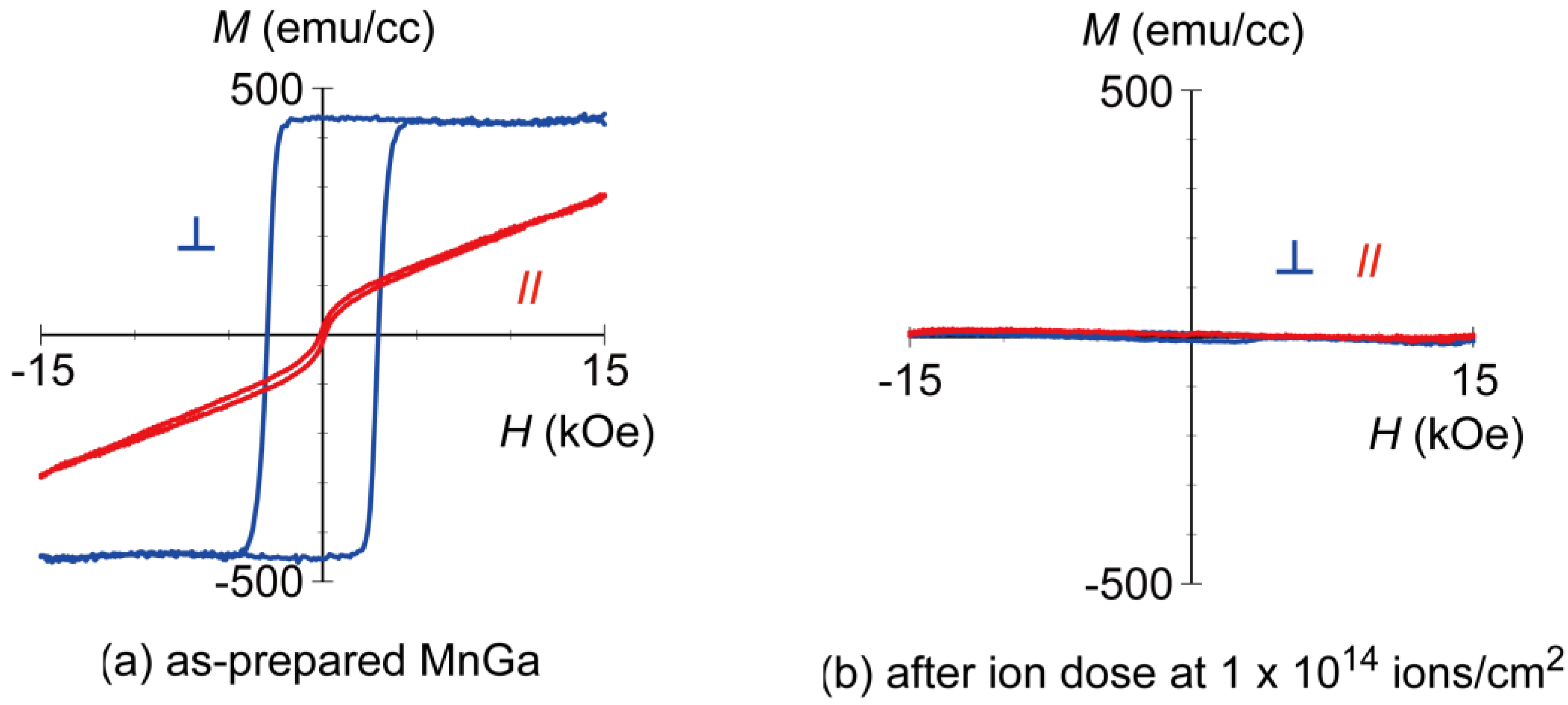
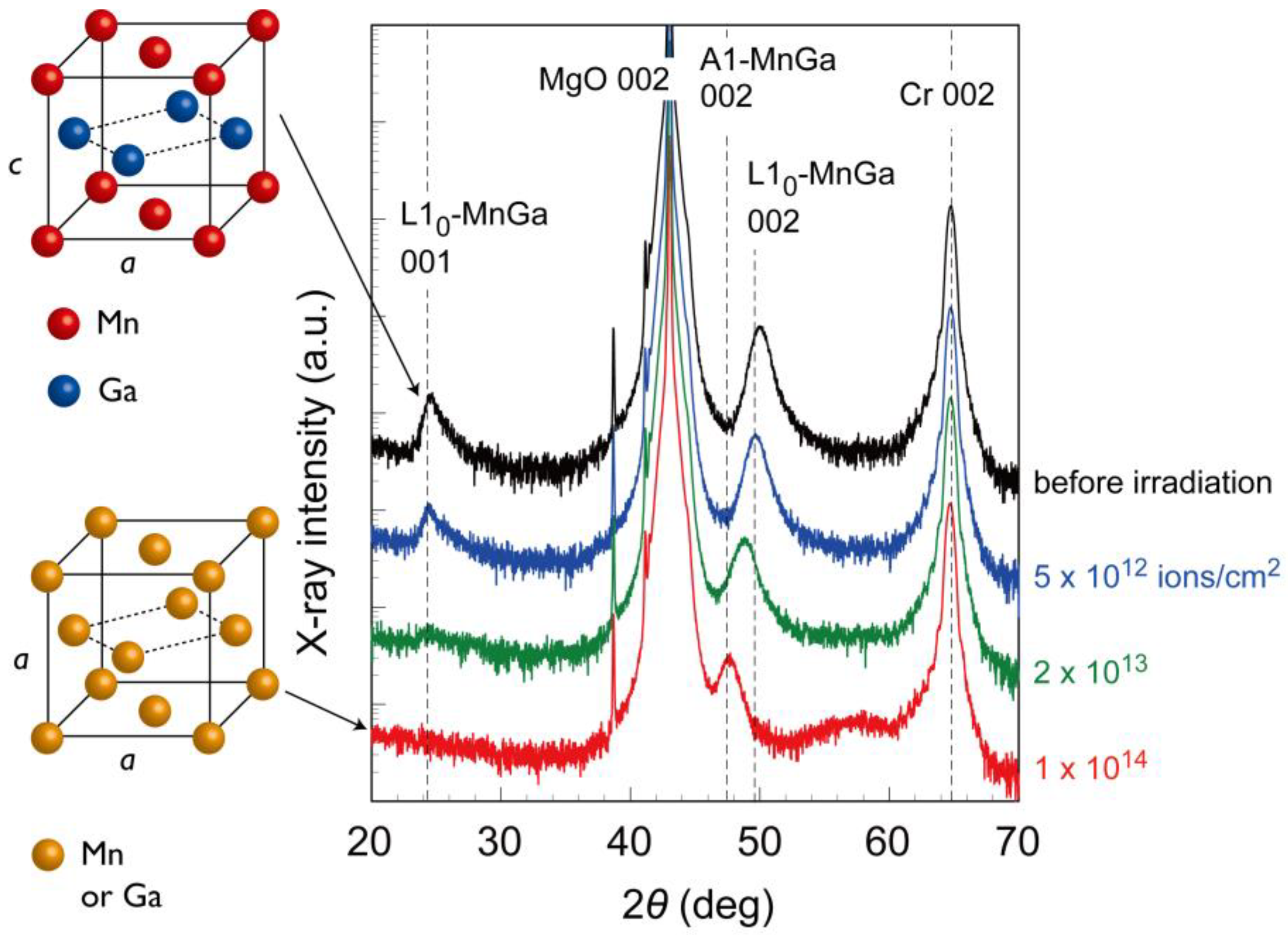
In a MnxGa100-x alloy system, L10 ordered phase is known to be stable for x = 0.5–0.65, and D022 phase is known to be stable for x = 0.65–0.75. The L10 and D022 MnGa films exhibit strong perpendicular magnetic anisotropy when the films were grown with (001) orientation [24]. Figure 1 shows M-H loops of MnGa films (a) before and (b) after the irradiation measured by an alternating gradient field magnetometer (AGM). The MnGa films were grown on MgO(001) substrate with (001)-oriented Cr (20 nm) buffer layer by the co-sputtering of Mn40Ga60 and Mn60Ga40 targets at 300 °C, and subsequently annealed at 400 °C. Then, 30 keV Kr+ ions were irradiated to the as-prepared MnGa to control the structure and magnetic properties of the MnGa film. The saturation magnetization Ms and effective anisotropy field Hkeff of the L10-MnGa film are estimated to be Ms ~450 emu/cc and Hkeff ~25 kOe, respectively. After the ion dose at 1 × 10¹⁴ ions/cm2, the ferromagnetism of the MnGa film disappeared (Figure 1b). Figure 2 shows the X-ray diffraction (XRD) profiles of the MnGa films before and after ion irradiation. In the profile before the irradiation, Cr and MnGa 002 peaks were clearly confirmed, indicating that the MnGa film has a (001)-oriented structure. Moreover, 001 MnGa superlattice peak indicates the formation of the ferromagnetic L10 ordered phase as shown in Figure 2. With an increase in the ion dose, the MnGa 001 peak decreased and the 002 peak shifted toward a lower angle. This indicates the phase change from the ferromagnetic L10 ordered phase to a paramagnetic A1 disordered phase by the ion irradiation as shown in Figure 2 (see also Refs. [20,22]). The variation of the XRD profiles explains well the change of the magnetic properties. The MnGa film exhibited a strong perpendicular magnetic anisotropy as shown in Figure 1a, since the MnGa film had a (001)-oriented L10 ordered structure before the irradiation. The ion irradiation at 1 × 10¹⁴ ions/cm2 completely changed the crystal structure to an A1 disordered phase, which makes the magnetism of the film paramagnetic as shown in Figure 1b.
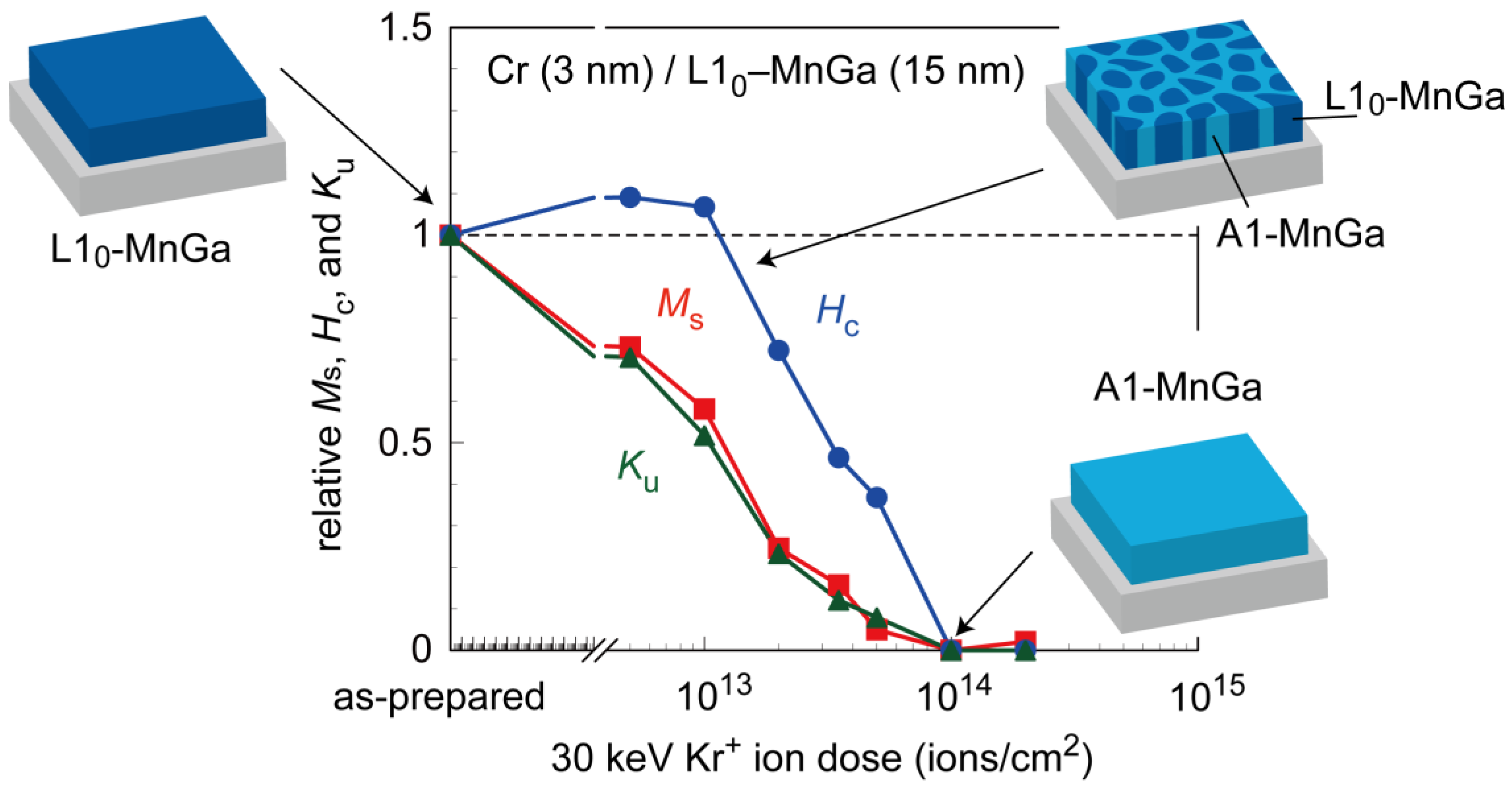
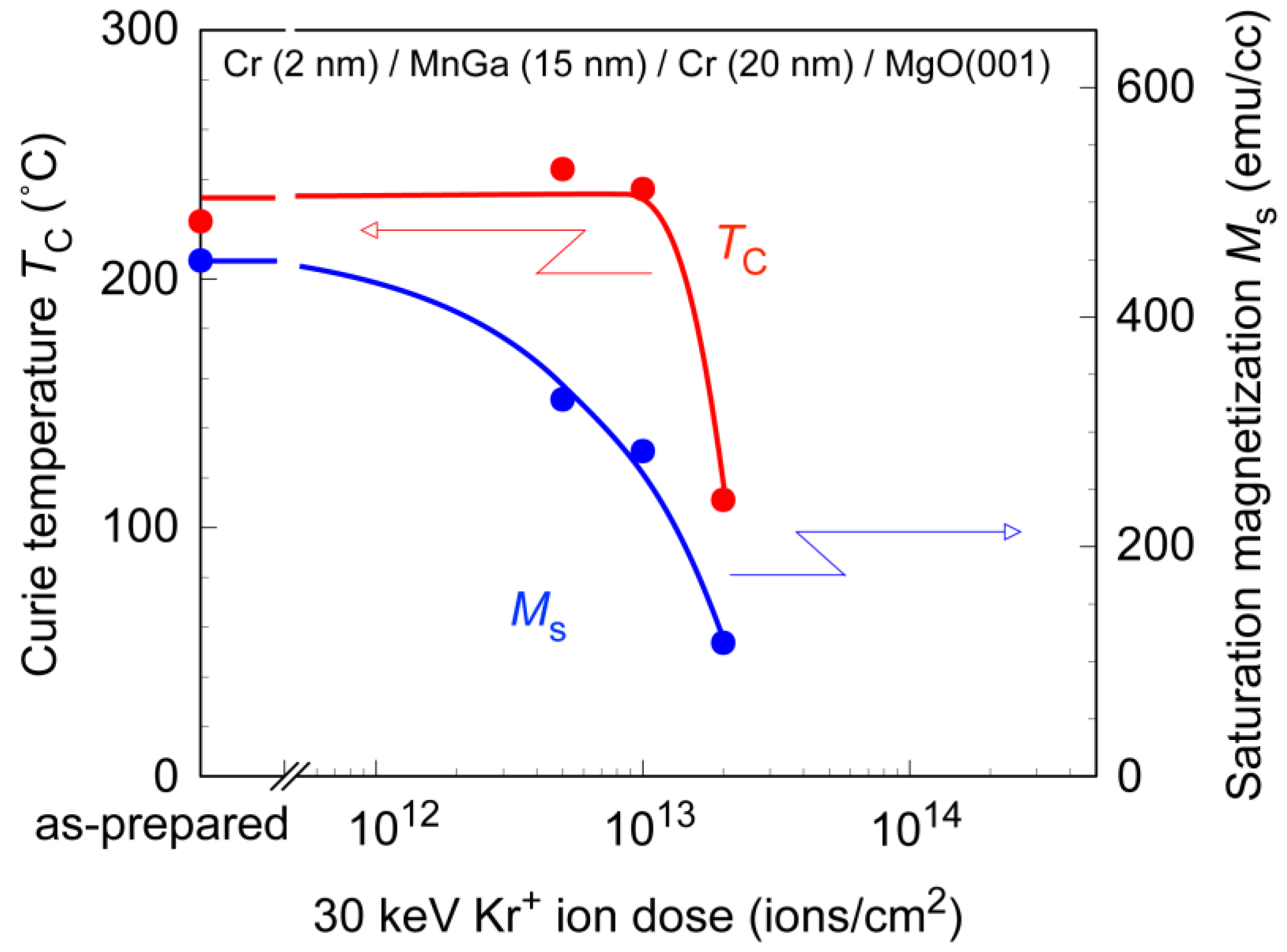
Figure 3 illustrates the 30 keV Kr+ ion dose dependences of the saturation magnetization Ms, coercivity Hc, and perpendicular anisotropy Ku of the MnGa films. These values were normalized as the values before the irradiation to be 1. Ms and Ku gradually decreased with increasing ion dose, whereas Hc increased slightly at the low ion dose up to 1013 ions/cm2 and then decreased with the increase in the ion dose. One can observe that Ku of the MnGa decreased in proportion to Ms. This implies that the reduction of Ms by the ion implantation is not caused by the decrease of the Curie temperature TC of the MnGa. The temperature dependence of Ku is known to be proportional to Ms2~Ms3, and thus if the ion irradiation causes the reduction of TC, Ku should decrease in proportion to Ms2~Ms3 [25,26]. Figure 4 shows the ion dose dependence of TC and Ms of MnGa films. As expected from the ion dose dependence of Ms and Ku shown in Figure 3, TC did not decrease up to the ion dose of 1013 ions/cm2. Based on these results, the microstructure of the ion-implanted MnGa is expected to be a mixture of the ferromagnetic L10-MnGa and paramagnetic A1-MnGa illustrated in Figure 3. The increase of Hc up to 1013 ions/cm2 in Figure 3 and the decrease of TC at 2 × 10¹⁴ ions/cm2 in Figure 4 are also explained by this microstructure. The ion dose of 1013 ions/cm2 corresponds to one ion per 3 nm × 3 nm square. We speculate that such an ion dose creates local nonmagnetic A1-MnGa regions which act as pinning centers to impede the smooth propagation of the domain wall, resulting in the increase of Hc. The gradual change of XRD profiles with the ion dose shown in Figure 2 is also explained by the microstructure shown in Figure 3, since the coherent length of the X-ray is much longer than the lateral size of the microstructure. The increase of the ion dose will increase the volume ratio of the A1 phase/L10 phase, and then the L10 MnGa nano-crystals will be surrounded by the paramagnetic A1 MnGa matrix. The L10-MnGa nano-crystal exhibits low Hc and TC compared to those of the L10-MnGa film due to the thermal fluctuation of the magnetization at room temperature. A significant increase of Hc of the ion-implanted MnGa with a decrease in the temperature was confirmed by a superconducting quantum interference device magnetometer [21] (data not shown), which also supports the above-described microstructure of the irradiated MnGa, i.e., L10 MnGa nano-crystals surrounded by the paramagnetic A1 MnGa matrix.
3. Magnetic Patterning of MnGa and the Switching Field Distribution of Patterned MnGa
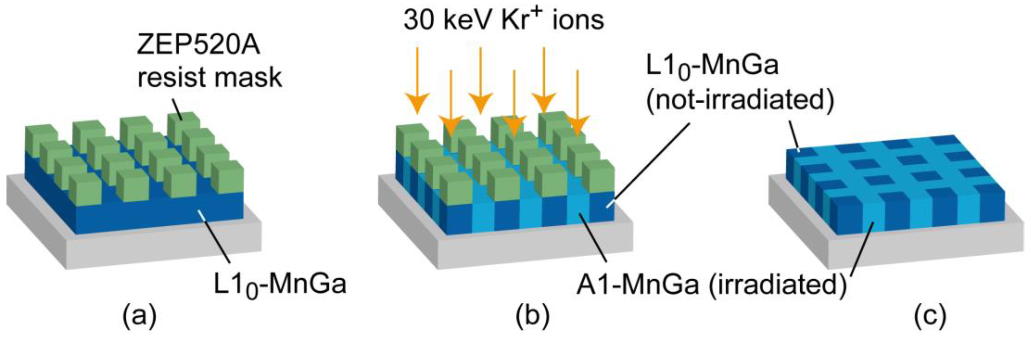
Figure 5 provides schematics of the fabrication process of magnetically patterned MnGa films. After the deposition of the L10-MnGa film, patterned resist (ZEP520A) masks were formed on the film by electron beam lithography (Figure 5a). Then, uniform ion irradiation at a dose of 1 × 10¹⁴ ions/cm2, which completely changes the magnetism of MnGa from ferromagnetic to paramagnetic as shown in Figure 3, was carried out through patterned resist masks (Figure 5b). Finally, the residual resist masks were removed by O2 plasma ashing by using reactive ion etching (Figure 5c).
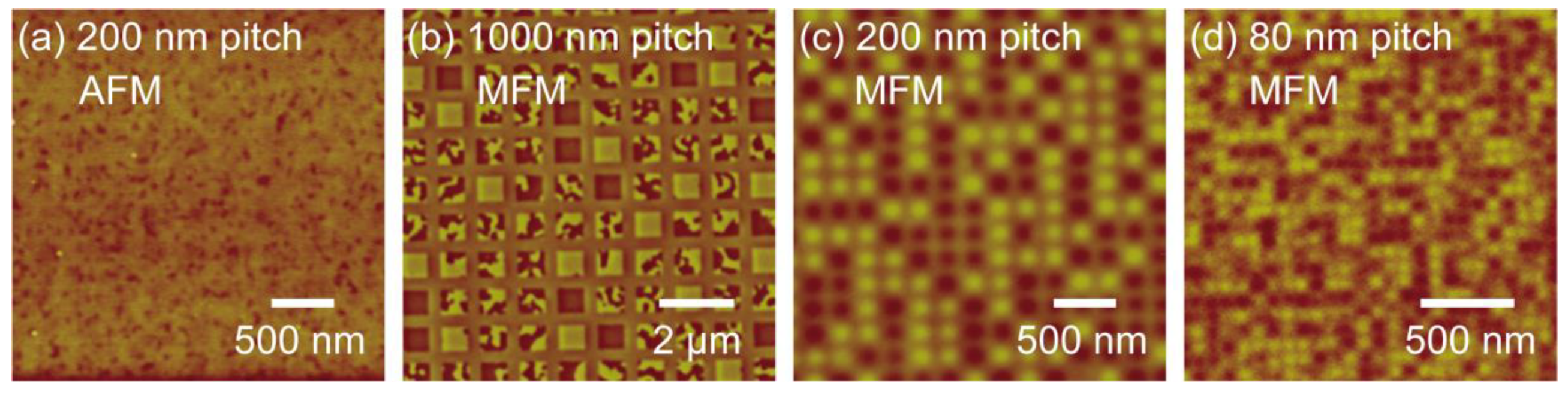
Figure 6 shows (a) atomic force microscope (AFM) and (b)–(d) magnetic force microscope (MFM) images of MnGa films patterned by local ion irradiation. The AFM image in Figure 6a was taken for the patterned MnGa with a pitch size of 200 nm. The surface roughness was Ra = 0.36 nm, and there was no topographical structure reflecting the square patterns seen in the MFM images. The MFM images show the domain structure of the patterned MnGa with pitch sizes of (b) 1000 nm, (c) 200 nm, and (d) 80 nm. All of the samples were demagnetized by alternating magnetic field before the MFM measurements. Bright and dark contrasts indicate the magnetization “up“ and “down“ in the film normal direction, respectively, and the intermediate contrast comes from the paramagnetic MnGa created by the ion irradiation. As seen in Figure 6b–d, bright and dark contrasts were observed in the square-shaped “bit” regions, whereas no magnetic contrast in the “space” regions. The patterned MnGa films have a sufficiently smooth surface with Ra less than 1 nm as shown in Figure 6a, however, the MnGa films have magnetic nanostructure as shown in Figure 6b–d, indicating that planar-patterned BPM are fabricated by the local ion irradiation without flattening processes. Some of the bits exhibit a multi-(maze) domain structure for the patterned MnGa with a pitch size 1000 nm, and the multi-domain structure in the bit was confirmed for the MnGa with a pitch size down to 500 nm (not shown in the figure). Further decrease of the pitch size changes the domain structure in the bit from multi-domain to single domain as shown in Figure 6c,d. Clear magnetic contrasts and sharp transition from up to down magnetization between the adjacent bits were confirmed even in the patterned MnGa with a pitch size of 80 nm as shown in Figure 6d. This indicates the paramagnetic MnGa spaces are effective in suppressing the exchange coupling between the ferromagnetic bits through the spaces, which is the major problem in the Co/Pt and Co/Pd planar BPM [11].
In order to discuss the magnetization process of planar-patterned MnGa, first-order reversal curves (FORCs) [27,28] of the patterned MnGa were measured by AGM and analyzed [29]. Details of the FORC analysis of the planar-patterned MnGa are described in the Ref. [22]. Figure 7 shows the bit size dependence of the average switching field Hsw and the switching field distribution ΔHsw/Hsw estimated from the FORC analysis. Hsw of the planar-patterned MnGa increased with decreasing the bit size. When the nano-dots in the BPM have a reduced perpendicular anisotropy at the edge (referred to as “bit edge damage”), Hsw of the BPM does not increase with decreasing the bit size, since a few nanometers of the edge damage result in an edge nucleation magnetization reversal [30]. In addition, the exchange coupling between the adjacent bits observed in the planar-patterned Co/Pd also reduces Hsw [11]. Therefore, planar-patterned MnGa fabricated by local ion irradiation is expected to have negligibly small bit edge damage as well as negligibly small exchange coupling between the adjacent bits even with a bit size of 40 nm.
The SFD, ΔHsw/Hsw, of the un-patterned MnGa film was 13%, and it was almost constant until the bit size was reduced to 500 nm (pitch size of 1000 nm). In these samples, the magnetization reversal process is dominated by nucleation and domain wall propagation. The SFDs in these samples are thought to be determined by the density of the pinning centers existing in the as-prepared MnGa film, which means that the SFD will be decreased by improving the quality of the MnGa films. The SFD increased from 13% to 20% when the bit size became less than 240 nm. We speculate that this increase is related to the transition of the magnetization reversal process from the domain wall propagation to coherent rotation, since the domain structure in the bit changed from a multi-domain structure to a single domain structure at around a bit size of 240 nm (pitch size of 500 nm) as discussed in Figure 6. A further increase of the SFD was observed when the bit size was less than 50 nm. We consider that bit size distribution is the main cause of the increase in the SFD in the small bit size region, as we discussed in detail previously [22]. From these results, optimization of the patterning processes and the quality of the as-prepared film are the key factors to achieve an SFD less than 10%, for the practical application of the MnGa planar BPM.
4. Magnetization Dynamics of Ion-Implanted MnGa
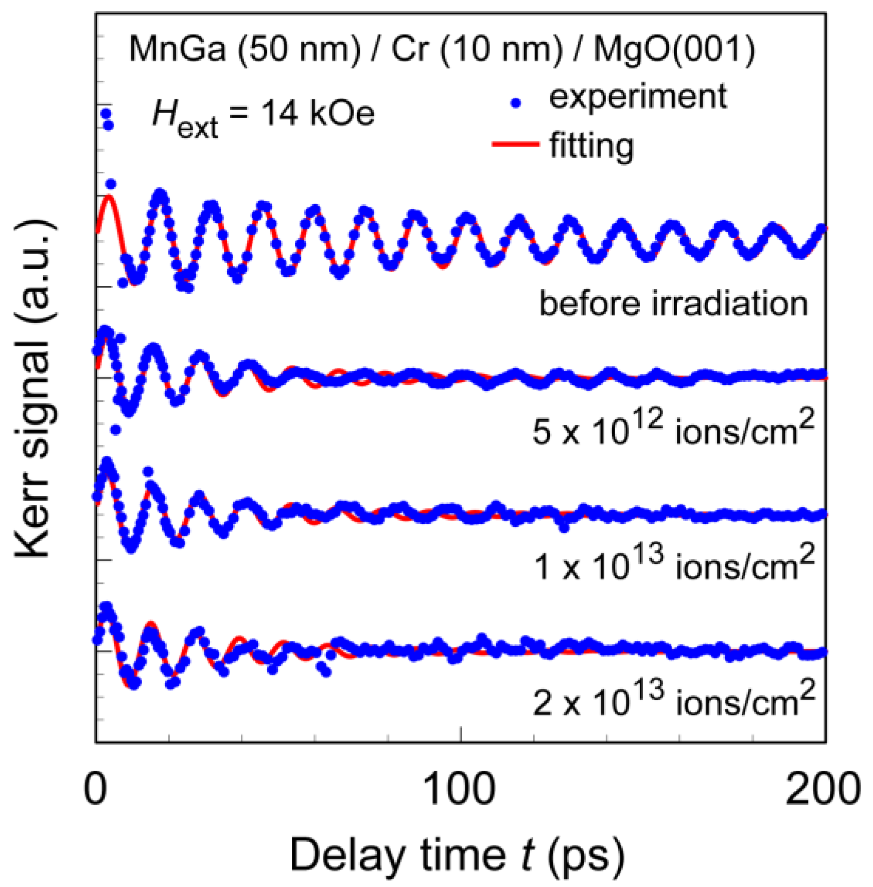
From the FORC analysis discussed in Figure 7, the planar-patterned MnGa is expected to have negligibly small bit edge damage. However, for a more detailed discussion, the anisotropy field of the irradiated MnGa with ion doses around 1013 ions/cm2, which is a transition region from ferromagnetic to paramagnetic as noted in Figure 2, should be investigated. We measured the time resolved magneto-optical Kerr effect (TRMOKE) of the ion-irradiated MnGa films to investigate the anisotropy field and its distribution. A high-power fiber laser with a central wavelength of 1041 nm, a pulse width of 500 fs, and a repetition frequency of 100 kHz was used to obtain the TRMOKE. The frequency-doubled and linearly polarized probe beam was incident normal to the film surface to monitor the perpendicular component of the magnetization after the illumination of the pump beam. The fluences of the pump and probe beams were 0.2 and 0.04 mJ/cm2, respectively. The external field up to Hext = 14 kOe was applied at an angle of θH = 60 deg from the film normal direction. Details of the TRMOKE setup are described in Refs. [31,32,33,34,35]. The sample stack used for the TRMOKE was SiN (5 nm)/MnGa (50 nm)/Cr (10 nm)/MgO(001), and after ion irradiation, an additional SiN (35 nm) layer was deposited to enhance the Kerr rotation of the MnGa. Figure 8 shows the decaying magnetization precessions of the MnGa before and after ion doses of 5 × 10¹², 1 × 10¹³, and 2 × 10¹³ ions/cm2 under Hext = 14 kOe. The raw data, measured by the TRMOKE, contain the signals of laser-induced demagnetization at the delay time of the probe beam t = 0 and exponential decay due to the recovery of the magnetization as described in Ref. [31]. These unnecessary signals were subtracted to extract the decaying precession triggered by the pump illumination as shown in Figure 8. The closed circles and solid lines in Figure 8 indicate the measured data and fitted curves with the damped oscillation function, A exp(–t/τ) sinωt, respectively, where τ is the relaxation time and ω the angular frequency of the oscillation. A clear oscillation due to the magnetization precession of the as-prepared MnGa can be seen in Figure 8, and the precessions of the MnGa after the ion dose were confirmed to relax faster than those of the MnGa before the ion dose.
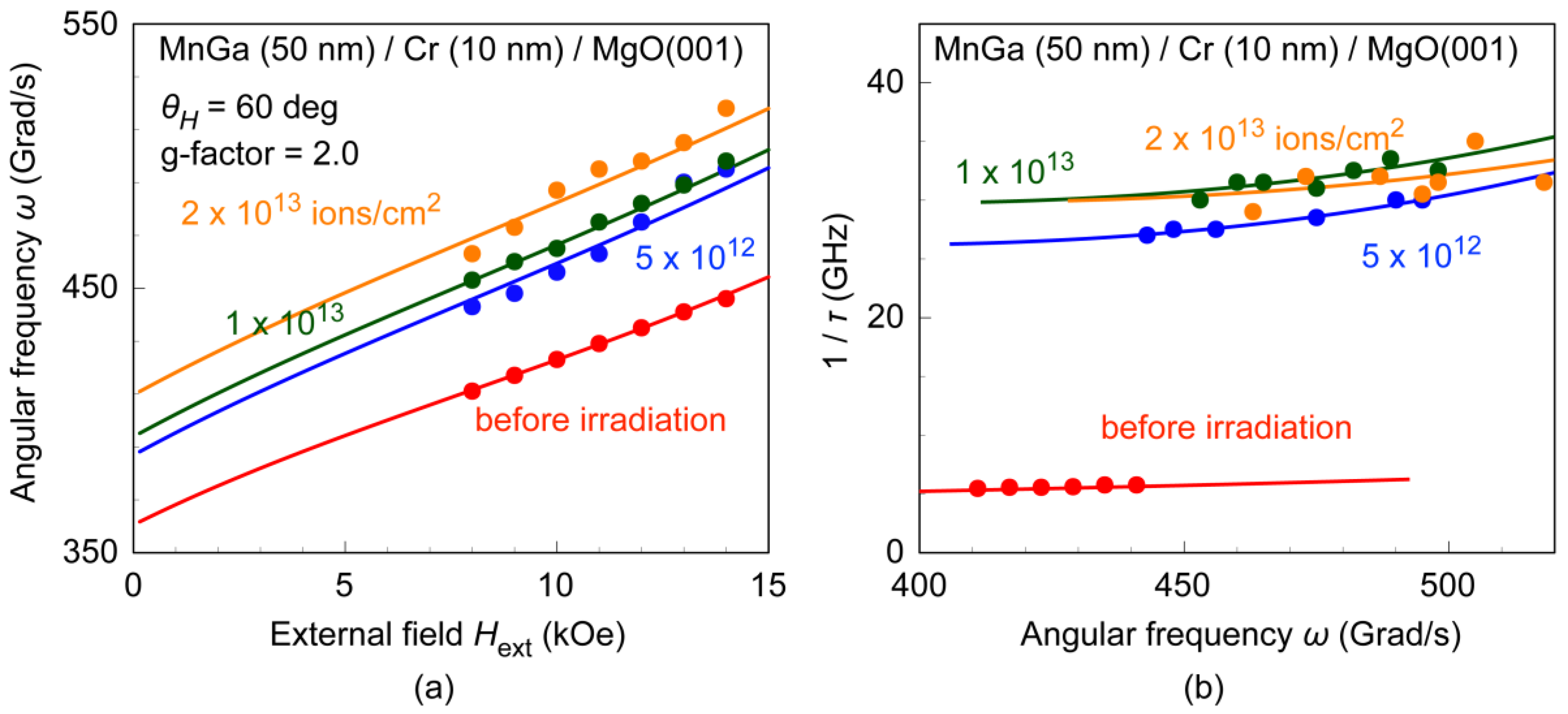
The effective anisotropy field Hkeff and g-factor g were estimated by fitting the Hext dependence of ω shown in Figure 9a with the following expressions [36,37]:
where is the gyromagnetic constant, and θ is the stable magnetization angle from the film normal estimated by minimizing the following magnetic energy:
Figure 9b shows the ω dependence of the inverse of the relaxation time 1/τ for the ion-dosed MnGa films. As shown in Figure 9b, 1/τ increased with increasing ω, and the slope for the MnGa without the ion dose is quite small, whereas the slope was found to increase after ion irradiation. 1/τ is influenced by Gilbert damping α, anisotropy distribution ΔHkeff, anisotropy axis distribution ΔθH, and two-magnon scattering (TMS) [37,38,39,40], and is expressed as,
if we neglect the contribution from spin pumping [41]. When the TMS and ΔθH are negligible and Hθθ0 ≈ Hφφ0, Equation (3) is simply expressed as:
indicating that 1/τ is roughly proportional to α [37]. From the data in Figure 9b, the slope and y-intercept for the MnGa without the ion dose are estimated to be 0.01 and 1.3 Grad/s, respectively, suggesting small α ~0.01 and ΔHkeff ~150 Oe. The TMS contribution is calculated as [38,39,40]:
where k is the magnon wave vector, k its amplitude, N0 the scattering intensity, C(k) the correlation function, ωk the spin wave dispersion, and δωk the inverse lifetime of the spin wave. These are expressed as [38,39]:
where ξ is the correlation length, and Hθθ(k) and Hφφ(k) are given by [38]:
where µ0 is the permeability of vacuum, Aex the exchange stiffness, and φk the azimuth angle of the spin wave. Nk is the wave number dependent demagnetizing factor which is given by [38]:
where d is the film thickness. 1/τTMS increases with increasing ω; i.e., it increases the slope in Figure 9b, since the increase of Hext increases θ. From Equations (5) and (6), 1/τTMS is proportional to ΔHkeff2, and thus the increase of ΔHkeff results in the increases of the slope of the curve of 1/τ vs. ω. The increase of ΔHkeff also increases the y-intercept of Figure 9b from Equation (4). In Figure 9b, the solid lines show fitted curves with Equation (3), where we assumed ΔθH = 0, since the second term in Equation (3) for the MnGa without ion irradiation was negligibly small, and the second term is considered not to increase after ion irradiation. We also assumed that the Gilbert damping stayed constant after ion irradiation, since the ion irradiation will not contribute to an increase in the intrinsic damping.
Figure 10 shows the ion dose dependence of Hkeff, ΔHkeff, α, and ξ of the ion-irradiated MnGa films. The g-factor of all MnGa films was estimated to be 2.0 irrespective of ion implantation. α of the as-prepared MnGa is estimated to be 0.008, which is consistent with the previous result [42]. Hkeff of the MnGa before the irradiation was 20 kOe, which roughly agrees with that estimated from M–H loops shown in Figure 1. Hkeff increased after the ion dose and stayed constant at Hkeff ~23 kOe. This suggests that the ion irradiation does not cause the reduction of the average value of the anisotropy, which is in accordance with the small bit edge damage in the patterned MnGa. On the other hand, ΔHkeff significantly increased from 0.2 kOe to 3 kOe with an increase in the ion dose. Accordingly, ξ decreased from 10 nm to 3 nm after the ion irradiation. These trends are explained by the microstructure discussed in Figure 2 and Figure 3. After the ion irradiation, L10 MnGa nano-crystals are expected to be surrounded by the paramagnetic A1 MnGa matrix. This results in a large distribution of the effective field acting in the nano-crystals, since each L10-MnGa nano-crystal has different shape anisotropy. For the thin-film MnGa, the demagnetizing field is estimated to be 7.5 kOe, whereas the demagnetizing field of an isolated MnGa nano-crystal with an aspect ratio of 1 will be 2.5 kOe. The microstructure also explains the reduction of ξ by the ion irradiation. ξ corresponds to the length of disorder in the film, and ξ ~10 nm for an as-prepared MnGa film is thought to be related to the grain size of the MnGa, which is expected to be a few tens of nanometers from the AFM image in Figure 6a. After ion irradiation, ξ will be reduced by the ion irradiation. The ion dose of 1 × 10¹³ ions/cm2 corresponds to 1 ion per 3 nm × 3 nm, which agrees well with ξ after ion irradiation.
5. Conclusions
We summarized the variation of the magnetic properties of MnGa films with ion irradiation, and reported the magnetic patterning and the SFD of MnGa fabricated by local ion irradiation. We also investigated the magnetization dynamics of irradiated MnGa films to study the origin of the SFD. The (001)-oriented L10-MnGa films grown on the Cr-buffered MgO(001) substrate exhibited strong perpendicular anisotropy, and the magnetization and perpendicular anisotropy of the MnGa were eliminated by a Kr+ ion dose of 1 × 10¹⁴ ions/cm2. The ion irradiation changes the crystal structure of MnGa from the ferromagnetic L10 phase to the paramagnetic A1 phase. The microstructure of MnGa after the ion dose of ~1013 ions/cm2 is expected to be a mixture of the ferromagnetic L10-MnGa and paramagnetic A1-MnGa.
Uniform ion implantation through patterned resist masks is effective in producing topographically flat and magnetically patterned MnGa, i.e., planar-patterned MnGa. We confirmed 40 nm × 40 nm magnetic bits on the MnGa patterned by this technique. The average switching field Hsw of the planar-patterned MnGa increased with decreasing the bit size, indicating the negligible bit edge damage in the patterned MnGa. However, the planar-patterned MnGa exhibits a rather large SFD of 25% for a bit size of ~40 nm. The improvement of the film quality, e.g., reduction of the density of the pinning centers, and the optimization of the patterning processes to reduce the bit size distribution will reduce the SFD.
Using the TRMOKE measurements, we evaluated the average anisotropy field Hkeff, its distribution ΔHkeff, the Gilbert damping α, and the length of disorder ξ. MnGa before ion irradiation exhibits large Hkeff = 20 kOe, small ΔHkeff = 200 Oe, and small α = 0.008. The MnGa films after the ion doses from 5 × 10¹² to 2 × 10¹³ ions/cm2 exhibited larger Hkeff of 22~23 kOe than that of the as-prepared MnGa. This suggests that the perpendicular anisotropy was not decreased by the ion dose, resulting in the small bit edge damage in the planar-patterned MnGa films. With the ion irradiation, ΔHkeff increased from 0.2 kOe to 3 kOe, whereas ξ decreased from 10 nm to 3 nm. These are explained by the model of the microstructure comprised of the ferromagnetic L10-MnGa and paramagnetic A1-MnGa, since the demagnetizing field and the length of disorder are expected to reduce significantly in the isolated L10-MnGa nano-crystal surrounded by paramagnetic A1-MnGa compared to the continuous L10-MnGa film.
Author Contributions
T.K. and S.I. planned the study. D.O. prepared the films and carried out the ion implantation and electron beam lithography. D.O. measured the magnetic properties and domain structure, and analyzed the results. T.K. measured and analyzed the TRMOKE. All authors discussed the results and commented on the manuscript.
Funding
This research was funded by the JSPS KAKENHI grant numbers 16H04328, 16K18091, 17H03249, and 17K8878, and also funded by the Project of Creation of Life Innovation Materials for Interdisciplinary and International Researcher Development of the Ministry of Education, Culture, Sports, Science and Technology (MEXT), Japan, and the Research Program of “Dynamic Alliance for Open Innovation Bridging Human, Environment and Materials” in “Network Joint Research Center for Materials and Devices”.
Acknowledgments
The authors thank M. Kumazawa of Nagoya University for his assistance with the experiments. The authors are grateful for financial support from the JSPS KAKENHI Grant Numbers 16H04328, 16K18091, 17H03249, 17K18878, and from the Project of Creation of Life Innovation Materials for Interdisciplinary and International Researcher Development of the Ministry of Education, Culture, Sports, Science and Technology (MEXT), Japan. A part of this work was performed under the Research Program of “Dynamic Alliance for Open Innovation Bridging Human, Environment and Materials” in “Network Joint Research Center for Materials and Devices”. A part of this work was conducted at the Nagoya University Nanofabrication Platform, supported by “Nanotechnology Platform Program” of MEXT, Japan.
Conflicts of Interest
The authors declare no conflict of interest.
References
- White, R.L.; New, R.M.H.; Fabian, R.; Pease, W. Patterned media: A viable route to 50 Gbit/in2 and up for magnetic recording? IEEE Trans. Magn. 1997, 33, 990–995. [Google Scholar] [CrossRef]
- Terris, B.D. Fabrication challenges for patterned recording media. J. Magn. Magn. Mater. 2009, 321, 512–517. [Google Scholar] [CrossRef]
- Kikitsu, A. Prospects for bit patterned media for high-density magnetic recording. J. Magn. Magn. Mater. 2009, 321, 526–530. [Google Scholar] [CrossRef]
- Charap, S.H.; Lu, P.-L.; He, Y. Thermal stability of recorded information at high densities. IEEE Trans. Magn. 1997, 33, 978–983. [Google Scholar] [CrossRef]
- Wood, R. The feasibility of magnetic recording at 1 terabit per square inch. IEEE Trans. Magn. 2000, 36, 36–42. [Google Scholar] [CrossRef]
- Choi, C.; Yoon, Y.; Hong, D.; Oh, Y.; Talke, F.E.; Jin, S. Planarization of patterned magnetic recording media to enable head flyability. Microsyst. Technol. 2011, 17, 395–402. [Google Scholar] [CrossRef] [Green Version]
- Chappert, C.; Bernas, H.; Ferré, J.; Kottler, V.; Jamet, J.-P.; Chen, Y.; Cambril, E.; Devolder, T.; Rousseaux, F.; Mathet, V.; Launois, H. Planar patterned magnetic media obtained by ion irradiation. Science 1998, 280, 1919–1922. [Google Scholar] [CrossRef]
- Ferré, J.; Chappert, C.; Bernas, H.; Jamet, J.-P.; Meyer, P.; Kaitasov, O.; Lemerle, S.; Mathet, V.; Rousseaux, F.; Launois, H. Irradiation induced effects on magnetic properties of Pt/Co/Pt ultrathin films. J. Magn. Magn. Mater. 1999, 198–199, 191–193. [Google Scholar]
- Hyndman, R.; Warin, P.; Gierak, J.; Ferré, J.; Chapman, J.N.; Jamet, J.-P.; Mathet, V.; Chappert, C. Modification of Co/Pt multilayers by gallium irradiation—Part 1: The effect on structural and magnetic properties. J. Appl. Phys. 2001, 90, 2843–3849. [Google Scholar] [CrossRef]
- Suharyadi, E.; Natsume, S.; Kato, T.; Tsunashima, S.; Iwata, S. Microstructure and magnetic properties of the FIB irradiated Co/Pd multilayer films. IEEE Trans. Magn. 2005, 41, 3595–3597. [Google Scholar] [CrossRef]
- Suharyadi, E.; Kato, T.; Tsunashima, S.; Iwata, S. Magnetic Properties of Patterned Co/Pd Nanostructures by E-Beam Lithography and Ga Ion Irradiation. IEEE Trans. Magn. 2006, 42, 2972–2974. [Google Scholar] [CrossRef]
- Hinoue, T.; Ito, K.; Hirayama, Y.; Hosoe, Y. Effects of lateral straggling of ions on patterned media fabricated by nitrogen ion implantation. J. Appl. Phys. 2012, 111, 07B912. [Google Scholar] [CrossRef]
- Gaur, N.; Kundu, S.; Piramanayagam, S.N.; Maurer, S.L.; Tan, H.K.; Wong, S.K.; Steen, S.E.; Yang, H.; Bhatia, C.S. Lateral displacement induced disorder in L10-FePt nanostructures by ion-implantation. Sci. Rep. 2013, 3, 1907. [Google Scholar] [CrossRef]
- Fassbender, J.; Liedke, M.O.; Strache, T.; Möller, W.; Menéndez, E.; Sort, J.; Rao, K.V.; Deevi, S.C.; Nogués, J. Ion mass dependence of irradiation-induced local creation of ferromagnetism in Fe60Al40 alloys. Phys. Rev. B 2008, 77, 174430. [Google Scholar] [CrossRef]
- Kato, T.; Iwata, S.; Yamauchi, Y.; Tsunashima, S.; Matsumoto, K.; Morikawa, T.; Ozaki, K. Planar patterned media fabricated by ion irradiation into CrPt3 ordered alloy films. J. Appl. Phys. 2009, 105, 07C117. [Google Scholar] [CrossRef]
- Kato, T.; Iwata, S.; Yamauchi, Y.; Tsunashima, S. Modification of magnetic properties and structure of Kr+ ion-irradiated CrPt3 films for planar bit patterned media. J. Appl. Phys. 2009, 106, 053908. [Google Scholar] [CrossRef]
- Suharyadi, E.; Oshima, D.; Kato, T.; Iwata, S. Switching field distribution of planar-patterned CrPt3 nanodots fabricated by ion irradiation. J. Appl. Phys. 2011, 109, 07B771. [Google Scholar] [CrossRef]
- Oshima, D.; Suharyadi, E.; Kato, T.; Iwata, S. Observation of ferri-nonmagnetic boundary in CrPt3 line-and-space patterned media using a dark-field transmission electron microscope. J. Magn. Magn. Mater. 2012, 324, 1617–1621. [Google Scholar] [CrossRef]
- Oshima, D.; Tanimoto, M.; Kato, T.; Fujiwara, Y.; Nakamura, T.; Kotani, Y.; Tsunashima, S.; Iwata, S. Modifications of Structure and Magnetic Properties of L10 MnAl and MnGa Films by Kr+ Ion Irradiation. IEEE Trans. Magn. 2014, 50, 3203407. [Google Scholar] [CrossRef]
- Oshima, D.; Kato, T.; Iwata, S.; Tsunashima, S. Control of Magnetic Properties of MnGa films by Kr+ Ion Irradiation for Application to Bit Patterned Media. IEEE Trans. Magn. 2013, 49, 3608–3611. [Google Scholar] [CrossRef]
- Oshima, D.; Tanimoto, M.; Kato, T.; Fujiwara, Y.; Nakamura, T.; Kotani, Y.; Tsunashima, S.; Iwata, S. Ion Irradiation-Induced Magnetic Transition of MnGa Alloy Films Studied by X-Ray Magnetic Circular Dichroism and Low-Temperature Hysteresis Loops. IEEE Trans. Magn. 2016, 52, 3201804. [Google Scholar] [CrossRef]
- Oshima, D.; Kato, T.; Iwata, S. Switching field distribution of MnGa bit patterned film fabricated by ion beam irradiation. IEEE Trans. Magn. 2018, 54, 3200207. [Google Scholar] [CrossRef]
- Xu, Q.; Kanbara, R.; Kato, T.; Iwata, S.; Tsunashima, S. Control of magnetic properties of MnBi and MnBiCu thin films by Kr+ ion irradiation. J. Appl. Phys. 2012, 111, 07B906. [Google Scholar] [CrossRef]
- Mizukami, S.; Kubota, T.; Wu, F.; Zhang, X.; Miyazaki, T.; Naganuma, H.; Oogane, M.; Sakuma, A.; Ando, Y. Composition dependence of magnetic properties in perpendicularly magnetized epitaxial thin films of Mn-Ga alloys. Phys. Rev. B 2012, 85, 014416. [Google Scholar] [CrossRef]
- Carr, W.J. Temperature dependence of ferromagnetic anisotropy. Phys. Rev. 1958, 109, 1971–1976. [Google Scholar] [CrossRef]
- Okamoto, S.; Kikuchi, N.; Kitakami, O.; Miyazaki, T.; Shimada, Y.; Fukamichi, K. Chemical-order-dependent magnetic anisotropy and exchange stiffness constant of FePt (001) epitaxial films. Phys. Rev. B 2002, 66, 024413. [Google Scholar] [CrossRef]
- Mayergoyz, I.D.; Friedman, G. Generalized Preisach model of hysteresis. IEEE Trans. Magn. 1988, 24, 212–217. [Google Scholar] [CrossRef]
- Pike, C.R.; Roberts, A.P.; Verosub, K.L. Characterizing interactions in fine magnetic particle systems using first order reversal curves. J. Appl. Phys. 1999, 85, 6660–6667. [Google Scholar] [CrossRef]
- Egli, R. VARIFORC: An optimized protocol for calculating non-regular first-order reversal curve (FORC) diagrams. Glob. Planet. Chang. 2013, 110, 302–320. [Google Scholar] [CrossRef]
- Shaw, J.M.; Russek, S.E.; Thomson, T.; Donahue, M.J.; Terris, B.D.; Hellwig, O.; Dobisz, E.; Schneider, M.L. Reversal mechanisms in perpendicular magnetized nanostructures. Phys. Rev. B 2008, 78, 024414. [Google Scholar] [CrossRef]
- Kato, T.; Nakazawa, K.; Komiya, R.; Nishizawa, N.; Tsunashima, S.; Iwata, S. Compositional dependence of g-factor and damping constant of GdFeCo amorphous alloy films. IEEE Trans. Magn. 2008, 44, 3380–3383. [Google Scholar] [CrossRef]
- Kato, T.; Matsumoto, Y.; Okamoto, S.; Kikuchi, N.; Kitakami, O.; Nishizawa, N.; Tsunashima, S.; Iwata, S. Time-resolved magnetization dynamics and damping constant of sputtered Co/Ni multilayers. IEEE Trans. Magn. 2011, 47, 3036–3039. [Google Scholar] [CrossRef]
- Kato, T.; Matsumoto, Y.; Kashima, S.; Okamoto, S.; Kikuchi, N.; Iwata, S.; Kitakami, O.; Tsunashima, S. Perpendicular anisotropy and Gilbert damping in Sputtered Co/Pd multilayers. IEEE Trans. Magn. 2012, 48, 3288–3291. [Google Scholar] [CrossRef]
- Higashide, T.; Dai, B.; Kato, T.; Oshima, D.; Iwata, S. Effective damping constant and current induced magnetization switching of GdFeCo/TbFe exchange-coupled bilayers. IEEE Mang. Lett. 2016, 7, 3505605. [Google Scholar] [CrossRef]
- Kimura, T.; Dong, X.; Adachi, K.; Oshima, D.; Kato, T.; Sonobe, Y.; Okamoto, S.; Kikuchi, N.; Kawato, Y.; Kitakami, O.; et al. Spin transfer torque switching of Co/Pd multilayers and Gilbert damping of Co-based multilayers. Jpn. J. Appl. Phys. 2018, 57, 09TD01. [Google Scholar] [CrossRef]
- Suhl, H. Ferromagnetic resonance in nickel ferrite between one and two kilomegacycles. Phys. Rev. 1955, 97, 555–557. [Google Scholar] [CrossRef]
- Beaujour, J.-M.; Ravelosona, D.; Tudosa, I.; Fullerton, E.E.; Kent, A.D. Ferromagnetic resonance linewidth in ultrathin films with perpendicular magnetic anisotropy. Phys. Rev. B 2009, 80, 180415(R). [Google Scholar] [CrossRef]
- McMichael, R.D.; Krivosik, P. Classical Model of Extrinsic Ferromagnetic Resonance Linewidth in Ultrathin Films. IEEE Trans. Magn. 2004, 40, 2–11. [Google Scholar] [CrossRef] [Green Version]
- Landeros, P.; Arias, R.E.; Mills, D.L. Two magnon scattering in ultrathin ferromagnets: The case where the magnetization is out of plane. Phys. Rev. B 2008, 77, 214405. [Google Scholar] [CrossRef]
- Iihama, S.; Sakuma, A.; Naganuma, H.; Oogane, M.; Mizukami, S.; Ando, Y. Influence of L10 order parameter on Gilbert damping constants for FePd thin films investigated by means of time-resolved magneto-optical Kerr effect. Phys. Rev. B 2016, 94, 174425. [Google Scholar] [CrossRef]
- Tserkovnyak, Y.; Brataas, A.; Bauer, G.E.W. Enhanced Gilbert damping in thin ferromagnetic films. Phys. Rev. Lett. 2002, 88, 117601. [Google Scholar] [CrossRef] [PubMed]
- Mizukami, S.; Wu, F.; Sakuma, A.; Walowski, J.; Watanabe, D.; Kubota, T.; Zhang, X.; Naganuma, H.; Oogane, M.; Ando, Y.; et al. Long-lived ultrafast spin precession in manganese alloys films with a large perpendicular magnetic anisotropy. Phys. Rev. Lett. 2011, 106, 117201. [Google Scholar] [CrossRef] [PubMed]
Figure 1.
M-H loops of MnGa films (a) before and (b) after the ion dose at 1 × 10¹⁴ ions/cm2. The loops were taken applying a magnetic field parallel or perpendicular to the film plane [20].
Figure 1.
M-H loops of MnGa films (a) before and (b) after the ion dose at 1 × 10¹⁴ ions/cm2. The loops were taken applying a magnetic field parallel or perpendicular to the film plane [20].

Figure 2.
X-ray diffraction profiles of MnGa films before and after Kr+ ion irradiation. The crystal structures of L10 ordered and A1 disordered phases are also shown.
Figure 2.
X-ray diffraction profiles of MnGa films before and after Kr+ ion irradiation. The crystal structures of L10 ordered and A1 disordered phases are also shown.

Figure 3.
The 30 keV Kr+ ion dose dependence of Ms, Hc, and Ku of MnGa film [20]. These values are normalized as the values of as-prepared MnGa to be 1. The ion dose changes the structure of MnGa from the L10 phase to the A1 phase, and the microstructure of the L10 phase surrounded by the A1 phase is expected at ~1 × 10¹³ ions/cm2 as shown in the figure [22].

Figure 4.
The 30 keV Kr+ ion dose dependence of TC and Ms of MnGa film.

Figure 5.
Schematics of the fabrication process of magnetically patterned MnGa films. Square shaped ZEP520A resist masks were fabricated by electron beam lithography (a), and the uniform ion irradiation were carried out through resist masks (b). Finally, the residual resist masks were removed by plasma ashing (c).

Figure 6.
(a) AFM images of the planar-pattered MnGa with a pitch size of 200 nm and MFM images of the planar-patterned MnGa with pitch sizes of (b) 1000 nm, (c) 200 nm, and (d) 80 nm [20,22].

Figure 7.
Dot size dependence of Hsw and ΔHsw/Hsw estimated from a first-order reversal curve (FORC) analysis of planar-patterned MnGa [22].
Figure 7.
Dot size dependence of Hsw and ΔHsw/Hsw estimated from a first-order reversal curve (FORC) analysis of planar-patterned MnGa [22].

Figure 8.
TRMOKE waveforms of MnGa films before and after the ion dose. The ion dose was varied from 5 × 10¹² to 2 × 10¹³ ions/cm2, and the external field of 14 kOe was applied at θH = 60 deg from the film normal direction. Closed circles and solid lines show measured data and fitted curves with damped oscillation function.

Figure 9.
(a) Hext dependence of ω and (b) ω dependence of 1/τ obtained by fitting the TRMOKE waveforms of MnGa films before and after the ion dose. The ion dose was varied from 5 × 10¹² to 2 × 10¹³ ions/cm2, and the external field was applied at θH = 60 deg from the film normal direction. Solid lines in (a,b) show fitted curves with Equations (1) and (3), respectively.

Figure 10.
The 30 keV Kr+ ion dose dependence of Hkeff, ΔHkeff, α, and ξ of the MnGa films before and after ion irradiation. These values were obtained by fitting with Equations (1) and (3).
Figure 10.
The 30 keV Kr+ ion dose dependence of Hkeff, ΔHkeff, α, and ξ of the MnGa films before and after ion irradiation. These values were obtained by fitting with Equations (1) and (3).

© 2019 by the authors. Licensee MDPI, Basel, Switzerland. This article is an open access article distributed under the terms and conditions of the Creative Commons Attribution (CC BY) license (http://creativecommons.org/licenses/by/4.0/).
Share and Cite
MDPI and ACS Style
Kato, T.; Oshima, D.; Iwata, S. Ion Irradiation for Planar Patterning of Magnetic Materials. Crystals 2019, 9, 27. https://0-doi-org.brum.beds.ac.uk/10.3390/cryst9010027
AMA Style
Kato T, Oshima D, Iwata S. Ion Irradiation for Planar Patterning of Magnetic Materials. Crystals. 2019; 9(1):27. https://0-doi-org.brum.beds.ac.uk/10.3390/cryst9010027
Chicago/Turabian StyleKato, Takeshi, Daiki Oshima, and Satoshi Iwata. 2019. "Ion Irradiation for Planar Patterning of Magnetic Materials" Crystals 9, no. 1: 27. https://0-doi-org.brum.beds.ac.uk/10.3390/cryst9010027
Note that from the first issue of 2016, this journal uses article numbers instead of page numbers. See further details here.