On Plowing Frictional Behavior during Scratch Testing: A Comparison between Experimental and Theoretical/Numerical Results


Department of Solid Mechanics, Royal Institute of Technology, SE-10044 Stockholm, Sweden
Crystals 2019, 9(1), 33; https://0-doi-org.brum.beds.ac.uk/10.3390/cryst9010033
Submission received: 26 November 2018
/
Revised: 24 December 2018
/
Accepted: 8 January 2019
/
Published: 11 January 2019
(This article belongs to the Special Issue Microstructure Evolutions and Mechanical Behavior of Semicrystalline Polymers)
Abstract
:Scratch testing is a contact mechanics based nondestructive testing method that, if correctly evaluated, can give a lot of information about the material and tribological behavior of a material. In contrast to the situation with another contact-based method, indentation testing, wear characteristics can also be investigated, for example. In order to get results of practical importance from a scratch test, it is necessary to have evaluation formulae available. Indeed, such formulae exist for scratch testing but can be substantially influenced by frictional effects. For this reason, closed-form analytical relations have been suggested for the purpose of accounting for such effects during scratching and in particular the plowing frictional effect. As a major benefit, these relations can also be of assistance during material characterization through scratch testing. However, the proposed existing relations are based solely on theoretical/numerical analyses and, remembering that the scratch test of course is an experimental approach, verification by experiments is a necessity. Such a task is performed in the present study and it is shown that, based on standard contact global properties, the relations are accurate for most polymeric materials but could also be used for some metallic ones.
1. Introduction
Scratch testing, as well as normal indentation, is frequently used for characterizing materials constitutively, in particular for thin film materials and at small length scales. When it comes to analyses of these two contact mechanics based methods, normal indentation is by far the most used. For the purpose of material characterization, the analyses by Tabor [1] and Johnson [2,3] are classical works devoted to classical elastic‒plastic materials. In these studies global indentation properties, i.e., normal hardness, Hn (average contact pressure), normal indentation load, Pn, and indentation depth curve, h, are related to elastic‒plastic material properties. It should also be mentioned that another important contact parameter is the actual area of contact necessary in order to calculate the hardness.
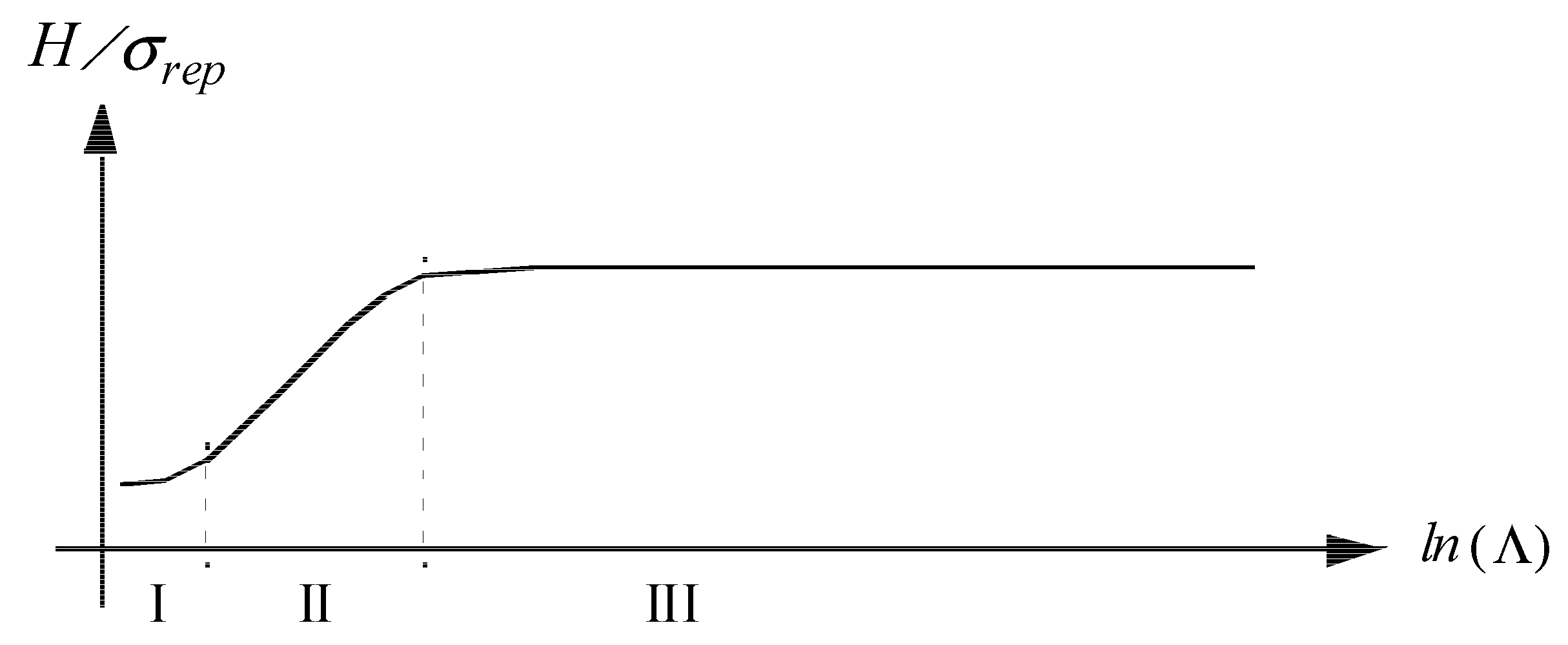
The analysis by Johnson [2,3] defined the fundamentals for a general analysis of indentation testing. For sharp indentation on classical Mises elastoplastic materials, this general correlation parameter, schematically shown in Figure 1, could be defined:
Λ = Etanβ/((1 − ν2)σrep)
In Equation (1), E is the Young’s modulus, ν is Poisson’s ratio, β is the angle between the (sharp) indenter and the undeformed surface, and σrep is the material flow stress at a representative value of the effective (accumulated) plastic strain εp. Based on the parameter Λ, three regions or levels of contact behavior can be defined. These levels, as shown in Figure 1, are:
- (1)
- Level I: Dominating elastic deformations, i.e., low indentation load, where elastic contact analysis is sufficient.
- (2)
- Level II: Elastic and plastic deformations are of equal magnitude.
- (3)
- Level III: Plastic deformations are dominant in the contact region.
In level II, it was determined by Johnson [2,3] that in this region
while in level III, Tabor [1] showed that at a sharp indentation
H = lnΛ,
H = Cσrep.
For a Vickers indenter C = 3 and εp ≈ 0.08 (Tabor [1]) and for a cone indenter C = 2.55 and εp = 0.11 (Atkins and Tabor [4]). The latter case is specified for a cone indenter with an angle of 22° between the indenter and the undeformed surface.
In a general situation, the simple formulae above might not be sufficient for high-accuracy results. This concerns, for example, the case when the material strain-hardening cannot be described by a regular power law hardening—cf. [5,6,7], where advanced finite element methods were utilized. Indeed, remembering the complexity of the indentation problem finite element methods is an essential part of the solution procedure, as specified in, for example, [5,6,7,8,9,10,11,12].
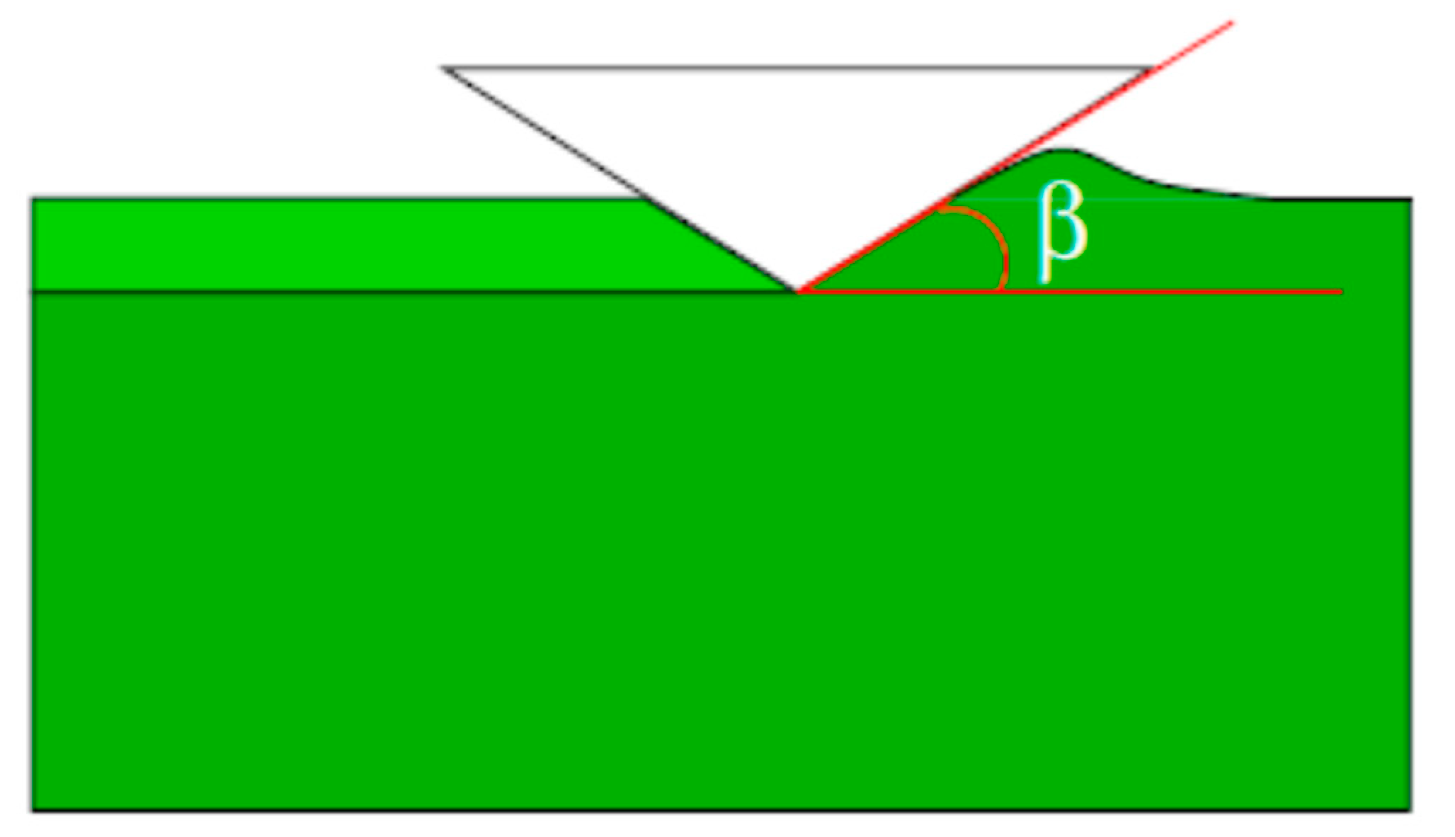
Finite element methods are obviously also a very important part of an analysis of scratch testing (visualized in Figure 2). This has been performed in [13,14,15,16,17,18,19,20,21] (just to mention a few). An important conclusion from these results is that the Johnson parameter [2,3], in Equation (1), also governed correlation during scratch problems. This was further clarified in [22,23], where explicit formulae for this correlation were presented for a number of global scratch quantities, accounting for the difference in scratch behavior at elastoplastic and rigid plastic scratching. One of these global scratch quantities investigated was the so-called apparent coefficient of friction, μ0, and this quantity will be further investigated presently. It goes almost without saying that experimental verification of these scratch relations is of greatest importance and this will be attempted here for the apparent coefficient of friction with predictions from [23]. These predictions will be compared to corresponding experimental results originally presented by Wredenberg and Larsson [19]. The experimental results are pertinent to both polymeric and metallic materials and, accordingly, a large range of values on the Λ–parameter in Equation (1) are covered. Both the theoretical/numerical and experimental results are valid for cone scratching with β = 22°; see Figure 2 for the indenter geometry, and classical elastoplasticity is relied upon as a foundation for the constitutive behavior.
2. Theoretical Background
The problem at issue concerns scratching using a sharp rigid conical stylus with β = 22° in Figure 2. The specimen is considered large and composed of a monolithic material. In the presentation below h is the normal indentation depth. Quasi-static and steady-state conditions, as well as classical elastoplasticity, are assumed and based on these restrictions; the problem is self-similar with no characteristic length present. Consequently, global indentation properties are independent of indentation depth h during the loading sequence of a scratch test on homogeneous materials. Here and in the rest of the paper the apparent coefficient of friction is defined as, cf. e.g., [19],
μ0 = μi + μp.
The decomposition in Equation (4) between an adhesive/interfacial part and a plowing part was originally suggested by Bowden and Tabor [24] but has also been verified numerically by Felder and Bucaille [15]. Furthermore, the plowing part of the apparent coefficient of friction depends on the mechanics of the scratch problem and it is possible to write
μp = μp(Λ).
From analytical considerations, cf. [25,26], it is possible to derive approximate estimates on μp(Λ). In short, it can be shown that at ideal rigid plastic behavior,
at cone scratching with β = 22°.
μp(Λ) = 0.26
In order to arrive at a more complete description of the Λ-dependence of μp also including strain-hardening plasticity, Larsson [23] studied the scratch problem using, as mentioned above, finite element methods. Regarding the constitutive details in [23], classical rate-independent elastoplasticity, accounting for large deformations, is assumed to prevail and the strain hardening behavior was based on a power law assumption according to
where σ(εp) is the flow stress, σY is the initial yield stress, εp is, as previously stated, the effective plastic strain, and n is the hardening exponent. The representative stress value is then defined as
where εrep is the effective strain at a representative value of the plastic strain.
σ(εp) = σY + σ0(εp)n,
σrep = σ(εrep),
Based on the results from finite element simulations, and within the basic assumptions discussed above, Larsson [23] suggested that the plowing part of the apparent coefficient of friction is very well correlated with the Johnson parameter Λ according to
with the choice of representative stress in Equation (1) being
μp(Λ) = 0.03 + 0.072lnΛ (Level II, Λ ≤ 20 approximately)
μp(Λ) = 0.26 (Level III, Λ ≥ 50 approximately),
μp(Λ) = 0.26 (Level III, Λ ≥ 50 approximately),
σrep = σ(εp = 0.25) (Level II, Λ ≤ 20 approximately)
σrep = σ(εp = 0.39) (Level III, Λ ≥ 25 approximately).
σrep = σ(εp = 0.39) (Level III, Λ ≥ 25 approximately).
In the analysis leading to Equations (9) and (10), frictional effects are not included in the numerical approach. This is due to the decomposition suggested by Bowden and Tabor [24], explicitly presented in Equation (4), indicating that interfacial and plowing frictional effects are separable. Accordingly, μp is the same for any value on μi and performing the numerical simulations with μi = 0 is then the obvious choice. Based on this discussion, it goes almost without saying that experimental verification of Equations (9) and (10) is crucial. This will also be attempted below, pertinent to materials described in the next section.
3. Experiments and Materials
In this section the experimental cone scratching results in [19] are detailed. Included in this discussion is also a description of the metallic and polymeric materials at issue in the present investigation.
In [19] cone scratching with an indenter angle β = 22° (see Figure 2) was performed on six different materials including three polymers and three metals. A diamond indenter was used in order to secure as much as possible a non-deforming stylus. The normal and tangential forces were recorded and, among other things, normal and scratch hardness were recorded.
It should be immediately stated that one of the materials, Aluminum 4120, showed anomalous behavior due to the formation of oxide on the aluminum surface. For that reason, this material is left out of the present comparison.
The material characteristics are shown in Table 1. The strain hardening behavior of the materials is specified in [19] and defined here by the values of the two representative stresses as specified in Equation (10).
Consequently, the experimental scratch results, pertinent to the plowing part of the apparent coefficient of friction, for the five materials are then compared with the predictions from Equations (9) and (10). This comparison will be presented and discussed below. It should be emphasized that the experimental scratch hardness values, presented and discussed below, are averages from the experiments and standard deviations are not shown for brevity. The latter feature is, however, clearly presented in [19].
4. Results and Discussion
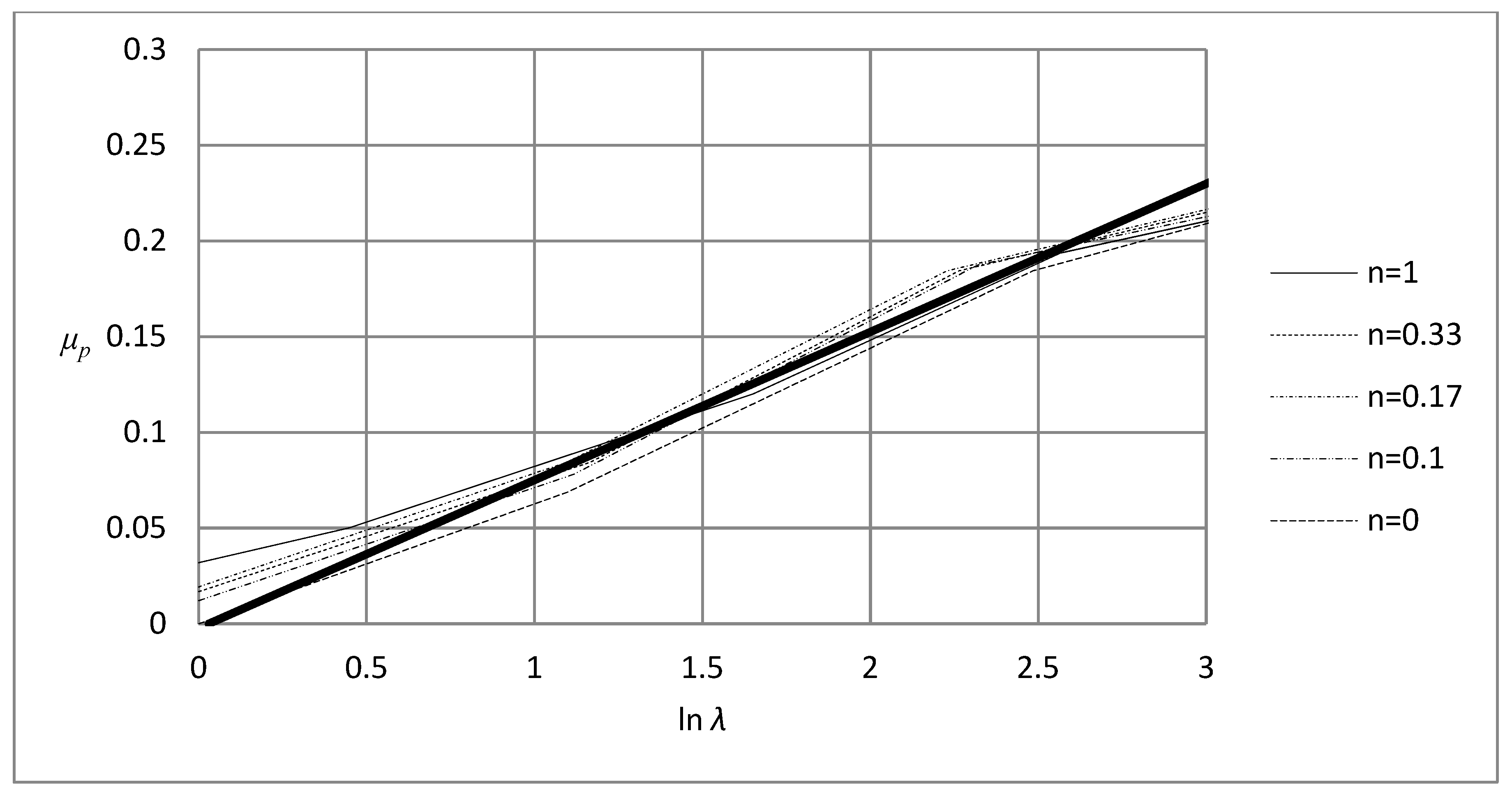
The theoretical/numerical predictions from [23], as detailed in Equations (9) and (10), will be compared with corresponding experimental results presented in [19]. In doing so, it seems appropriate to describe the theoretical/numerical results leading to the relations in Equation (9). This is done in Figure 3 and Figure 4. In doing so, the representative stress measures in the figures are always the ones presented in Equation (10).
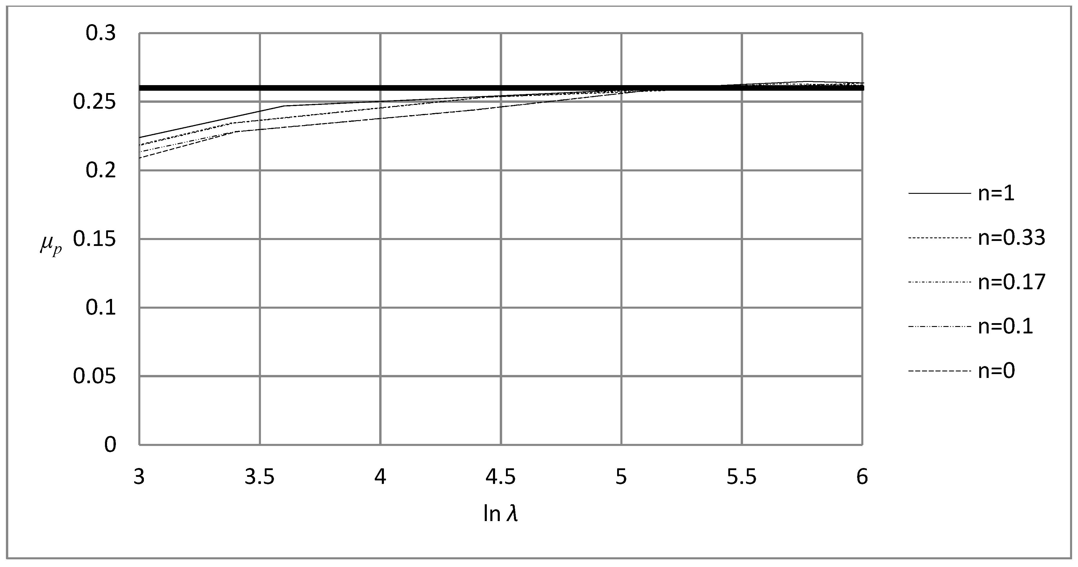
In Figure 3, relevant for level II contact, and Figure 4, relevant for level III contact, the results for the plowing part of the apparent coefficient of friction, μp, are shown as first presented in [23]. Results for different values of the power law exponent n, in Equation (7), are depicted together with the predictions from Equation (9). According to Equation (10), then, in Figure 3, σ(εp = 0.25) is used as a representative stress and, correspondingly in Figure 4, σ(εp = 0.39) is used. Clearly, except for very low values of lnΛ where the elastic level I contact effects are intervening, and at the transition between level II and level III contact, the different curves come together as a single universal curve with good accuracy. This universal curve is then represented by Equation (9), with the representative stresses as detailed in Equation (10). It should be noted in passing that the numerical results show good agreement with Equation (6) in the level III contact regime.
The main purpose of the present study is to determine if the universal results in Figure 3 and Figure 4, and specifically the relations presented in Equations (9) and (10), are sufficient to predict experimental results for the materials presented and described in Table 1. Consequently, the representative stresses determined previously and presented in Equation (10) are used to determine the experimental values on the plowing part of the apparent coefficient of friction, μp, for the materials in Table 1 and then compared with the predictions from Equations (9) and (10). The outcome of this comparison is detailed in Figure 5 and Figure 6.
To start, in Figure 5 results for the plowing part of the apparent coefficient of friction are shown for level II contact conditions. This corresponds to the upper Equation (9), which is identified as the continuous straight line in the figure. Corresponding experimental results for the three polymers in Table 1 are also shown. Clearly, the agreement between predictions and experiments is very good except for the case of the polymeric material PMMA, where the predictions are somewhat high but within the standard deviation.
Corresponding results for level III rigid plastic contact are shown in Figure 6. Also, in this case the agreement between predictions and experimental results is good even though the explicit value on μp for Al7050 is somewhat high compared with the predictions. The difference can, however, be explained by experimental uncertainties but also due to the fact that the Λ-values for Al7050 are close to the transition zone between level II and level III contact. Indeed, if the upper relation in Equation (9) is used to predict the experimental results for Al7050 (instead of the lower relation in Equation (9) as in Figure 6) then almost perfect agreement is found between predictions and experimental results (in both cases μp = 0.3 is found). This is not unusual behavior, though, when contact mechanics testing is correlated using the Johnson parameter Λ defined in Equation (1). Indeed, this feature is also present at straightforward normal indentation testing where hardness (normalized using a representative stress) values overshoot in the transition zone and then reach a constant value as level III is properly achieved, cf. [12]. This is the same behavior indicated by the experimental results for Al7050 in Figure 6. Obviously, this suggests that special care has to be taken when using the relations in Equation (9) at transitional contact (i.e., at transition between level II and level III contact); this would be a very interesting subject for further studies.
The results shown in Figure 5 and Figure 6 are encouraging as they suggest that the relations shown in Equations (9) and (10) are sufficient (in most cases) for accurate prediction of the plowing part of the apparent coefficient of friction. The results also indicate that the plowing frictional behavior is well described from an analysis assuming no interfacial friction.
Also, thin film scratching has been studied a lot recently, cf. e.g., [27,28,29,30,31,32,33,34,35,36,37,38], and the investigations concern aspects such as fracture, delamination behavior (as described in [39,40]), the behavior of different global and local scratch variables, and alternative constitutive behavior. Even though thin films introduce a characteristic length into the problem, the outcome of the present study can be used at least as a guideline to analyze the mechanics of thin film scratching.
In the author’s opinion, the most significant finding is the tools to predict (and analyze) the frictional behavior at scratch testing in both the elastoplastic and the rigid plastic contact regime. While this feature was previously rather well known in the case of metals, the present results also make it possible to account for the frictional effects of scratching for polymers. The applications of scratch testing could then include:
- Material characterization (together with similar relations for global scratch properties).
- Determination of the interfacial friction coefficient.
- Determination of the cracking behavior at scratching based on FEM calculations where the frictional behavior is properly accounted for.
5. Conclusions
Correlation of global quantities at scratch testing has been studied. In particular, this concerns the plowing part of the apparent coefficient of friction. It has been shown previously that within the framework of classical Mises elastoplasticity and quasi-static conditions, correlation can be achieved by using a combination of stresses at different levels of plastic strains to define representative quantities at scratching, accounting for the difference in mechanical behavior at elastoplastic and rigid plastic scratching. This correlation is detailed in explicit relations and these relations are compared to the experimental results for a wide range of materials ranging from polymers to metals. In general, good agreement is found between the two sets of results.
Funding
This research was funded by Swedish Research Council grant number 621-2005-5803
Conflicts of Interest
The author declares no conflict of interest
References
- Tabor, D. Hardness of Metals; Cambridge University Press: Cambridge, UK, 1951. [Google Scholar]
- Johnson, K.L. The correlation of indentation experiments. J. Mech. Phys. Solids 1970, 18, 115–126. [Google Scholar] [CrossRef]
- Johnson, K.L. Contact Mechanics; Cambridge University Press: Cambridge, UK, 1985. [Google Scholar]
- Atkins, A.G.; Tabor, D. Plastic indentation in metals with cones. J. Mech. Phys. Solids 1965, 13, 149–164. [Google Scholar] [CrossRef]
- Giannakopoulos, A.E.; Larsson, P.L.; Vestergaard, R. Analysis of Vickers indentation. Int. J. Solids Struct. 1994, 31, 2679–2708. [Google Scholar] [CrossRef]
- Larsson, P.L.; Giannakopoulos, A.E.; Söderlund, E.; Rowcliffe, D.J.; Vestergaard, R. Analysis of Berkovich indentation. Int. J. Solids Struct. 1996, 33, 221–248. [Google Scholar] [CrossRef]
- Mesarovic, S.D.; Fleck, N.A. Spherical indentation of elastic-plastic solids. Int. J. Solids Struct. 2000, 37, 7071–7091. [Google Scholar] [CrossRef]
- Bhattachharya, A.K.; Nix, W.D. Finite element simulation of indentation experiments. Int. J. Solids Struct. 1988, 24, 881–891. [Google Scholar] [CrossRef]
- Bhattachharya, A.K.; Nix, W.D. Analysis of elastic and plastic deformation associated with indentation testing of thin films on substrates. Int. J. Solids Struct. 1988, 24, 1287–1298. [Google Scholar] [CrossRef]
- Laursen, T.A.; Simo, J.C. A study of the mechanics of microindentation using finite elements. J. Mater. Res. 1992, 7, 618–626. [Google Scholar] [CrossRef]
- Mesarovic, S.D.; Fleck, N.A. Frictionless indentation of dissimilar elastic–plastic spheres. Proc. R. Soc. Lond. A 1999, 455, 2707–2728. [Google Scholar] [CrossRef]
- Larsson, P.L. Investigation of sharp contact at rigid plastic conditions. Int. J. Mech. Sci. 2001, 43, 895–920. [Google Scholar] [CrossRef]
- Bucaille, J.L.; Felder, E.; Hochstetter, G. Mechanical analysis of the scratch test on elastic and perfectly plastic materials with three-dimensional finite element modeling. Wear 2001, 249, 422–432. [Google Scholar] [CrossRef]
- Bucaille, J.L.; Felder, E.; Hochstetter, G. Experimental and three-dimensional finite element study of scratch test of polymers at large deformations. J. Tribol. 2004, 126, 372–379. [Google Scholar] [CrossRef]
- Felder, E.; Bucaille, JL. Mechanical analysis of the scratching of metals and polymers with conical indenters at moderate and large strains. Tribol. Int. 2006, 39, 70–87. [Google Scholar] [CrossRef]
- Bellemare, S.; Dao, M.; Suresh, S. The frictional sliding response of elasto-plastic materials in contact with a conical indenter. Int. J. Solids Struct. 2007, 44, 1970–1989. [Google Scholar] [CrossRef] [Green Version]
- Wredenberg, F.; Larsson, P.L. On the numerics and correlation of scratch testing. J. Mech. Mater. Struct. 2007, 2, 573–594. [Google Scholar] [CrossRef] [Green Version]
- Ben Tkaya, M.; Zidi, M.; Mezlini, S.; Zahouani, H.; Kapsa, P. Influence of the attack angle on the scratch testing of an aluminium alloy by cones: Experimental and numerical studies. Mater. Des. 2008, 29, 98–104. [Google Scholar] [CrossRef]
- Wredenberg, F.; Larsson, P.L. Scratch testing of metals and polymers—Experiments and numerics. Wear 2009, 266, 76–83. [Google Scholar] [CrossRef]
- Aleksy, N.; Kermouche, G.; Vautrin, A.; Bergheau, J.M. Numerical study of scratch velocity effect on recovery of viscoelastic-viscoplastic solids. Int. J. Mech. Sci. 2010, 52, 455–463. [Google Scholar] [CrossRef]
- Bellemare, S.; Dao, M.; Suresh, S. A new method for evaluating the plastic properties of materials through instrumented frictional sliding tests. Acta Mater. 2010, 58, 6385–6392. [Google Scholar] [CrossRef]
- Larsson, P.L. On the correlation of scratch testing using separated elastoplastic and rigid plastic descriptions of the representative stress. Mater. Des. 2013, 43, 153–160. [Google Scholar] [CrossRef]
- Larsson, P.L. On representative stress correlation of global scratch quantities at scratch testing of elastoplastic materials. Mater. Des. 2013, 49, 536–544. [Google Scholar] [CrossRef]
- Bowden, F.P.; Tabor, D. The Friction and Lubrication of Solids; Clarendon Press: Oxford, UK, 1950. [Google Scholar]
- Goddard, J.; Wilman, H. A theory of friction and wear during the abrasion of metals. Wear 1962, 5, 114–135. [Google Scholar] [CrossRef]
- Subhash, G.; Zhang, W. Investigation of the overall friction coefficient in single-pass scratch test. Wear 2002, 252, 123–134. [Google Scholar] [CrossRef]
- Bull, S.J. Failure modes in scratch adhesion testing. Surf. Coat. Technol. 1991, 50, 25–32. [Google Scholar] [CrossRef]
- Frey, N.; Mettraux, P.; Zambelli, G.; Landolt, D. Modified scratch test for study of the adhesion of ductile coatings. Surf. Coat. Technol. 1993, 63, 167–172. [Google Scholar] [CrossRef]
- Thouless, M.D. An analysis of spalling in the microscratch test. Eng. Fract. Mech. 1998, 61, 75–81. [Google Scholar] [CrossRef]
- Malzbender, J.; De With, G. Scratch testing of hybrid coatings of float glass. Surf. Coat. Technol. 2001, 135, 202–207. [Google Scholar] [CrossRef]
- Yueguang, W.; Manhong, Z.; Shan, T. Characterization of the fracture work for ductile film undergoing the micro-scratch. Acta Mech. Sin. 2002, 18, 494–505. [Google Scholar] [CrossRef]
- Holmberg, K.; Laukkanen, A.; Ronkainen, H.; Wallin, K.; Varjus, S. A model for stresses, crack generation and fracture toughness calculation in scratched tin-coated steel surfaces. Wear 2003, 254, 278–291. [Google Scholar] [CrossRef]
- Larsson, P.L.; Wredenberg, F. On indentation and scratching of thin films on hard substrates. J. Phys. D Appl. Phys. 2008, 41, 074022. [Google Scholar] [CrossRef]
- Kermouche, G.; Aleksy, N.; Loubet, J.L.; Bergheau, J.M. Finite element modeling of the scratch response of a coated time-dependent solid. Wear 2009, 267, 1945–1953. [Google Scholar] [CrossRef]
- Wredenberg, F.; Larsson, P.L. Delamination of thin coatings at scratching—Experiments and numerics. J. Mech. Mater. Struct. 2009, 4, 1041–1062. [Google Scholar] [CrossRef]
- Culha, O.; Zor, M.; Gungor, M.A.; Arman, Y.; Toparli, M. Evaluating the bond strength of opaque material on porcelain fused to metal restorations (PFM) alloys by scratch test method. Mater. Des. 2009, 30, 3225–3228. [Google Scholar] [CrossRef]
- Roy, S.; Darque-Ceretti, E.; Felder, E.; Raynal, F.; Bispo, I. Experimental analysis and finite element modelling of nano-scratch test applied on 40–120 nm SiCN thin films deposited on Cu/Si substrate. Thin Solid Films 2010, 518, 3859–3865. [Google Scholar] [CrossRef]
- Zheng, X.H.; Tu, J.P.; Song, R.G. Microstructure and tribological performance of CN(x)–TiN(x) composite films prepared by pulsed laser. Mater. Des. 2010, 31, 1716–1719. [Google Scholar] [CrossRef]
- Larsson, P.L. On delamination buckling and growth in circular and annular orthotropic plates. Int. J. Solids Struct. 1991, 27, 15–28. [Google Scholar] [CrossRef]
- Hutchinson, J.W.; Suo, Z. Mixed mode cracking in layered materials. Adv. Appl. Mech. 1992, 29, 63–191. [Google Scholar]
Figure 1.
Sketch of the characteristic behavior at indentation [4]. The indentation hardness H divided by the representative stress σrep is plotted against the non-dimensional strain parameter Λ. The different levels at indentation are indicated.
Figure 1.
Sketch of the characteristic behavior at indentation [4]. The indentation hardness H divided by the representative stress σrep is plotted against the non-dimensional strain parameter Λ. The different levels at indentation are indicated.

Figure 2.
Schematic of the scratching problem. The angle β defines the geometry of the conical stylus, where β = 22°. The scratch direction is from left to right.
Figure 2.
Schematic of the scratching problem. The angle β defines the geometry of the conical stylus, where β = 22°. The scratch direction is from left to right.

Figure 3.
Plowing part of the apparent coefficient of friction, μp, as a function of ln Λ, where Λ is the Johnson parameter defined in Equation (1). The representative stress is determined from σrep = σ(εp = 0.25). The results are taken from Larsson [23]. The thick line represents upper Equation (9).

Figure 4.
Plowing part of the apparent coefficient of friction, μp, as a function of ln Λ, where Λ is the Johnson parameter defined in Equation (1). The representative stress is determined from σrep = σ(εp = 0.39). The results are taken from Larsson [23]. The thick line represents lower Equation (9).

Figure 5.
Plowing part of the apparent coefficient of friction, μp, as a function of ln Λ, where Λ is the Johnson parameter defined in Equation (1). The representative stress is determined from σrep = σ(εp = 0.25). The thick line represents upper Equation (9). (●), experimental results for PMMA as detailed in Table 1. Results taken from Wredenberg and Larsson [19]. (■), experimental results for epoxy as detailed in Table 1. Results taken from Wredenberg and Larsson [19]. (▲), experimental results for vinyl ester as detailed in Table 1. Results taken from Wredenberg and Larsson [19]. The standard deviations are 0.035 (PMMA), 0.033 (epoxy) and 0.021 (vinyl ester).

Figure 6.
Plowing part of the apparent coefficient of friction, μp, as a function of ln Λ where Λ is the Johnson parameter defined in Equation (1). The representative stress is determined from σrep = σ(εp = 0.39). The thick line represents lower Equation (9). (●), experimental results for Al7050, as detailed in Table 1. Results taken from Wredenberg and Larsson [19]. (■), experimental results for stainless steel as detailed in Table 1. Results taken from Wredenberg and Larsson [19]. The standard deviations are 0.009 (Al7050) and 0.009 (stainless steel).


Table 1.
Material properties as presented by Wredenberg and Larsson [19] and utilized in the present analysis. The value of Young’s modulus is given in GPa, while all stress quantities are given in MPa. The parameter Λ, as defined in Equation (1), is dimensionless.
Table 1.
Material properties as presented by Wredenberg and Larsson [19] and utilized in the present analysis. The value of Young’s modulus is given in GPa, while all stress quantities are given in MPa. The parameter Λ, as defined in Equation (1), is dimensionless.
| Material | E | σY | σ(εp = 0.25) | σ(εp = 0.39) | Λ(εp = 0.25) | Λ(εp = 0.39) |
|---|---|---|---|---|---|---|
| Vinyl Ester | 3.5 | 108 | 108 | 108 | 15 | 15 |
| PMMA | 2.9 | 110 | 110 | 110 | 12 | 12 |
| Epoxy | 3.1 | 97 | 97 | 97 | 14 | 14 |
| Al7050 | 70 | 560 | 724 | 816 | 42.5 | 38 |
| Stainless steel | 200 | 560 | 625 | 805 | 146 | 113 |
© 2019 by the author. Licensee MDPI, Basel, Switzerland. This article is an open access article distributed under the terms and conditions of the Creative Commons Attribution (CC BY) license (http://creativecommons.org/licenses/by/4.0/).
Share and Cite
MDPI and ACS Style
Larsson, P.-L. On Plowing Frictional Behavior during Scratch Testing: A Comparison between Experimental and Theoretical/Numerical Results. Crystals 2019, 9, 33. https://0-doi-org.brum.beds.ac.uk/10.3390/cryst9010033
AMA Style
Larsson P-L. On Plowing Frictional Behavior during Scratch Testing: A Comparison between Experimental and Theoretical/Numerical Results. Crystals. 2019; 9(1):33. https://0-doi-org.brum.beds.ac.uk/10.3390/cryst9010033
Chicago/Turabian StyleLarsson, Per-Lennart. 2019. "On Plowing Frictional Behavior during Scratch Testing: A Comparison between Experimental and Theoretical/Numerical Results" Crystals 9, no. 1: 33. https://0-doi-org.brum.beds.ac.uk/10.3390/cryst9010033
Note that from the first issue of 2016, this journal uses article numbers instead of page numbers. See further details here.