Anion Influence on the Packing of 1,3-Bis(4-Ethynyl-3-Iodopyridinium)-Benzene Halogen Bond Receptors


Department of Chemistry and Biochemistry, University of Montana, 32 Campus Dr, Missoula, MT 59812, USA
*
Author to whom correspondence should be addressed.
Crystals 2019, 9(10), 522; https://doi.org/10.3390/cryst9100522
Submission received: 23 August 2019
/
Revised: 4 October 2019
/
Accepted: 8 October 2019
/
Published: 11 October 2019
(This article belongs to the Special Issue Halogen-Bonded Cocrystals)
Abstract
:Rigid and directional arylethynyl scaffolds have been widely successful across diverse areas of chemistry. Utilizing this platform, we present three new structures of a dicationic 1,3-bis(4-ethynyl-3-iodopyridinium)-benzene halogen bonding receptor with tetrafluoroborate, nitrate, and hydrogen sulfate. Structural analysis focused on the receptor conformation, anion shape, solvation, and long range packing of these systems. Coupled with our previously reported structures, we concluded that anions can be classified as building units within this family of halogen bonding receptors. Two kinds of antiparallel dimers were observed for these dicationic receptors. An off-centered species was most frequent, present among geometrically diverse anions and assorted receptor conformations. In contrast, the centered antiparallel dimers were observed with receptors adopting a bidentate conformation in the solid-state. While anions support the solid-state formation of dimers, the molecular geometry and characteristics (planarity, rigidity, and directionality) of arylethynyl systems increase the likelihood of dimer formation by limiting efficient packing arrangements. The significantly larger cation may have considerable influence on the solid-state packing, as similar cationic arylethynyl systems also display these dimers.
1. Introduction
The supramolecular chemistry of anions has been of considerable interest in the past few decades, largely motivated by environmental and health concerns [1,2,3,4,5]. Additionally, supramolecular chemists have used anions as templates to synthesize higher order structures in solution [6]. As a natural extension, crystal engineers have also explored anions as building components for the construction of multicomponent crystals [7]. These crystalline materials, which contain two or more individual molecular components, frequently exhibit altered physiochemical properties compared to the individual components [8,9,10], highlighting their value to many industries. As interest in multicomponent solids has increased, the need for more specific classifications has grown, resulting in (currently) conflicting nomenclature [11,12,13]. Forgoing terminology discussions, the use of formal charges to build multicomponent solids is an appealing tactic, as charge balance necessitates the presence of two molecular entities (unless zwitterionic in nature). The synthesis of charged species is obtained in various ways, the most common being acid-base proton transfer. A common example is the combination of carboxylic acids and amines, which produces a robust charge assisted hydrogen bond synthons through the formation of strong hydrogen bond donors (ammonium) and acceptors (carboxylate). This tactic has led to the development of guidelines predicting proton transfer upon crystallization based on the pKa of coformers [14]. In addition to proton transfer between two organic components, protonation of basic sites with inorganic acids, such as hydrochloric acid, leads to crystalline materials with charged tectons. This approach is common in the pharmaceutical industry where many drugs are sold as the hydrochloride species [14]. Alternatively, alkylation of Lewis basic sites (e.g., quaternization of amines) also produces charged components, frequently with inorganic anions. Alkylation, unlike proton transfer, does not guarantee the generation of a strong hydrogen bond donor. However, alkylation can enhance nearby hydrogen bond donors, and can significantly augment halogen bond strength [15,16].
The halogen bond is an attractive and highly directional (C-X···LB angle > 150°, LB = Lewis Base, X = halogen) noncovalent interaction between a polarizable electron-deficient halogen and an electron rich Lewis base [17]. Since its revival in the early 2000s [14], the halogen bond has been employed in diverse applications in chemistry [18,19,20] and biochemistry [21,22]. The linearity of the halogen bond has led to selective anion binding [18], organocatalysis [23,24,25], and self-assembly [26,27,28,29,30]. This directionality can also lead to more predictable solid-state structures with anions, and has been a topic of review [31,32].
Using inorganic anions as crystal engineering building blocks presents unique opportunities and challenges [7]. First, the high charge density and defined shape make them desirable tectons with strong and (fairly) predictable contacts with Lewis acids. On the other hand, the high charge density elicits strong solvation, complicating solvent removal during crystallization and resulting in undesirable solvates. Additionally, inorganic anions are often multidentate Lewis acid acceptors, which can complicate designs. Despite these difficulties, the extensive field of anion supramolecular chemistry offers a wealth of data to analyze. Frequently solid-state studies are complementary to solution data, resulting in analysis of binding modes, host-guest stoichiometry, and noncovalent contact parameters to quantify interaction strength. Analysis of anion interactions and subsequent packing from a crystal engineering standpoint is less common.
Arylethynyl scaffolds have been successfully used in various supramolecular chemistry fields, including coordination complexes and host-guest systems [33,34,35]. The rigidity and directionality afforded by the alkyne bond makes it a favorable structure to build upon. Although directional, alkynes exhibit conformational flexibility due to their low rotational barrier. For example, our 1,3-bis(4-ethynyl-3-iodopyridinium)-benzene system readily adopts three planar conformations as shown in Scheme 1. Inspired by the rich history of these systems, and our interest in halogen bonding, we combined the two to produce the first bis-ethynyl bidentate pyridinium halogen bonding receptors [36].
Leveraging the directionality of the halogen bond, we produced bidentate halogen bond anion receptors [36,37,38] as well as extended halogen bond oligomers that self-assemble around iodide and bromide to form triple-helicates [29,30]. Building on this initial work, a second-generation bidentate system introduced the hydrogen bond-enhanced halogen bond as a method to preorganize the conformationally flexible arylethynyl receptor as well as augment the halogen bond [39]. With a primary focus on halogen bonding in the solution phase, the interplay between cation and anion on the solid-state packing of these bidentate systems was largely overlooked from a crystal engineering standpoint. Herein, we report three new structures of the dicationic 1,3-bis(4-ethynyl-3-iodopyridinium)-benzene system, with tetrafluoroborate, nitrate, and hydrogen sulfate. Structural evaluation of these crystals focuses on receptor conformation, anion shape, solvation, and long range packing of these systems. The discussion is expanded to include previously reported structures to identify the common packing features of this family of compounds.
2. Materials and Methods
2.1. Synthesis
The synthesis of 1,3-bis(4-ethynyl-3-iodopyridinium)-benzene scaffolds and the neutral parent compounds have been previously reported [36]. 1 was synthesized with a small modification as methylation of the neutral species was carried out using trimethyloxonium tetrafluoroborate rather than methyl triflate (Scheme 2). The crystal structure of 2 was produced by adding tetra-n-butylammonium nitrate to a solution of 1. Similarly, 3 was produced by adding tetra-n-butylammonium hydrogen sulfate to the previously reported 4 [36]. For individual crystal growth conditions see the Results and Discussion sections.
Synthesis of (1)
In a round bottom flask, trimethyloxonium tetrafluoroborate 0.139 grams (0.939 mmol, 2.5 mol eq.) was dissolved in 5 mL dichloromethane under dry nitrogen gas. In a separate round bottom flask, 0.200 grams (0.375 mmol, 1 mol eq.) of neutral starting material was dissolved in 5 mL dichloromethane under nitrogen gas. The neutral receptor solution was added to the trimethyloxonium tetrafluoroborate solution dropwise at room temperature. Once fully added, the solution was stirred for 48 h. An off-white precipitate formed that was filtered off and washed with dichloromethane. The material was then used to grow crystals without further purification or characterization.
2.2. Data Collection and Refinement
X-ray diffraction data for 1 and 2 were collected at 100 K and 3•MeOH at 150 K. Data for all structures were collected on a Bruker D8 Venture using MoΚα-radiation (λ = 0.71073 Å). Data have been corrected for absorption using the SADABS [40] area detector absorption correction program. Using Olex2 [41], the structures were solved with the SHELXT [42] structure solution program using direct methods and refined with the SHELXL [43] refinement package using least squares minimization. All non-hydrogen atoms were refined with anisotropic thermal parameters. Calculations and refinement of the structures were carried out using APEX2 [44], SHELXTL [45], and Olex2 software. The details of the individual structure refinement are summarized below, while key crystal details and structure parameters are shown in Table 1. Images with atomic numbering schemes can be found in the Supplementary Materials (Figures S1–S3).
1—Hydrogen atoms in the investigated structure were placed in geometrically calculated positions and refined using a riding model. Isotropic thermal parameters of all hydrogen atoms were fixed to 1.2 times the U value of the atoms they are linked to (1.5 times for methyl groups).
2—Hydrogen atoms in the investigated structure were placed in geometrically calculated positions and refined using a riding model. Isotropic thermal parameters of the placed hydrogen atoms were fixed to 1.2 times the U value of the atoms they are linked to (1.5 times for methyl groups). The hydrogen atoms of both hydrogen sulfate anions were unable to be located from the difference map, therefore the hydrogen atoms on these anions have not been placed. The structure was found to contain indistinguishable solvent molecules residing in voids within the lattice. Attempts at modeling this solvent were not able to produce a suitable model. The SQUEEZE [46] routine within PLATON [47] was utilized to account for the residual, diffuse electron density and the model is refined against these data. A total of 219 electrons per unit cell were corrected for.
3•MeOH—Hydrogen atoms attached to heteroatoms were found from the residual density maps, placed, and refined with isotropic thermal parameters. All other hydrogen atoms were placed in geometrically calculated positions and refined using a riding model. Isotropic thermal parameters of the placed hydrogen atoms were fixed to 1.2 times the U value of the atoms they are linked to (1.5 times for methyl groups). The hydrogen atom bound to the oxygen of the methanol required both bond distance (DFIX 0.84 0.02) and 1,3 atom distance restraints (DANG 1.85 0.04) to produce a model that was reasonable and stable for refinement. The structure also displays several larger residual electron density peaks all < 1 Å from iodine atoms. These residual electron density peaks are arranged in a symmetrical fashion around the iodine atoms and are attributed to Fourier truncation ripples. Various absorption corrections were assessed; however, elimination of these effects was unsuccessful.
CCDC 1936528-1936530 contain the crystallographic data for 1, 3•MeOH, and 2, respectively. These data can be obtained free of charge via http://www.ccdc.cam.ac.uk/cgi-bin/catreq.cgi, or from the Cambridge Crystallographic Data Centre, 12 Union Road, Cambridge CB2 1EZ, UK; fax: (+44)-1223-336-033; or e-mail: [email protected].
2.3. Cambridge Structural Database (CSD) Search
ConQuest [48] (version 2.0.1) was used to collect and measure contact data from the CSD [49] (version 5.40 updates through Nov 2019) for halogen bonds to organic fluorine and boron atoms. Halogen bond donor atoms were restricted to iodine and bromine. To examine organic halogen bond donor species, these donors were restricted to having one bound atom (carbon). Halogen bond distances and angles were restricted to ≤ ∑vdW radii and 150.0–180.0°. The search was limited to strictly organic structures to eliminate any possible influence of well-defined metal coordination geometries. No restrictions on disorder or R value were implemented to augment the small data set.
2.4. Computational Analysis
2.5. Reporting Halogen Bond Contacts
Halogen bond contacts are frequently quantified by the contact distance to a Lewis base. This is often reported as a percentage of the van der Walls radii or as a ratio. The ratio has been given various names such as the halogen bond interaction ratio, normalized interaction distance, or reduction ratio. The ratio is defined as RXA = dXA/(XvdW + AvdW), where dXA is the measured distance (Å) from the halogen donor (X) and the acceptor (A), divided by the sum of the van der Walls radii (Å) of X and A. The ratio notation RXA further informs the reader as X is replaced with the atomic symbol of the halogen bond donor while the A denotes the atomic symbol of the halogen bond acceptor atom. Smaller ratio values indicate strong halogen bond interactions. Van der Walls radii that were used were taken from Alvarez [53].
3. Results
3.1. Structural Analysis of New Crystals
3.1.1. Analysis of 1
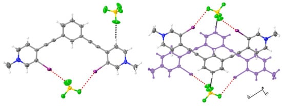
Diffraction quality crystals of 1 were grown by slow evaporation of an acetonitrile solution of 1, producing colorless plates. The complex crystalizes in the space group P21/c with one receptor, and two tetrafluoroborate anions. The receptor adopts the bidentate conformation (Scheme 1) and halogen bonds to a tetrafluoroborate anion. The iodine donors form contact with two distinct fluorine atoms with distances and angles of C-I···F (I2∙∙∙F1) 3.100(8) Å (RIF = 0.8857) 173.5(3)° and C-I···F (I1∙∙∙F4) 3.396(7) Å (RIF = 0.97028) 161.2(3)° (Table 2) (Figure 1). Evaluations of fluorine atoms participating in halogen bonds have been reported [54,55,56] and the structural parameters of the contacts in 1 provide evidence of fluorine as a halogen bond acceptor. A search of the CSD (using parameters outlined in the Methods section) revealed 91 structures with 105 unique halogen bond contacts (C-I···F) between organic iodine donors and fluorine, whereas the organic bromine halogen bond donor search returned 195 structures producing 226 unique C-Br···F contacts. With the CSD recently eclipsing 1 million structures, this certainly highlights its rarity.
Another uncommon contact in 1 involves the boron atom of the tetrafluoroborate. Here, an iodine donor contacts a boron with structural parameters of C-I···B (I2∙∙∙B1) 3.767(13) Å (RIB 0.95367) 164.1(3)° (Table 2). To our knowledge, discussions of boron halogen bond acceptors have been minimal, and limited to in silico studies [57,58]. The geometrical solid-state definition of a halogen bond implies its presence in 1. However, boron halogen bond acceptors (based on the criteria stated in the Methods section) are rare, as a search of the CSD indicates few (37 structures) examples with organic iodine and bromine donors. Of these structures, 20 exhibited halogen bonding to both boron and fluorine. This suggests that most of the boron-halogen contacts, in the database, arise due to close juxtaposition of fluorine acceptors and boron atoms. Structure 1 highlights this idea as the iodine···fluorine contact is shorter and more linear than the iodine···boron contact (Table 2 C-I···F (I2∙∙∙F1) and C-I···B (I2∙∙∙B1)). Simply put, the contact observed between the iodine and boron in 1 is a consequence of the halogen bond to the fluorine, the proximity of the boron atom, and close crystal packing. This demonstrates that just because structural parameters suggest a contact, it does not necessarily constitute an attractive noncovalent interaction.
The other tetrafluoroborate anion of 1 is located outside the bidentate binding pocket and exhibits disorder that was modeled over two positions (approx. 84:16). The principle position of the anion accepts two C-H hydrogen bonds, with a C-H···F distances and angles of 2.342(15) Å 176.6(8)° and 2.312(7) Å 161.8(6)°. Planes generated by the pyridinium rings deviate with respect to the central benzene plane by 11.33° and 13.17°. The distortion is likely a consequence of the centered antiparallel dimer (Figure 1). Here a C-H hydrogen bond from the central benzene core forms with a fluorine of the tetrafluoroborate in the bidentate pocket with a C-H···F distance and angle of 2.297(9) Å and 170.5(6)°. Columns of these dimers propagate in the crystallographic a direction, while adjacent columns arrange in a herringbone manner (Figure 2), both of which are held together by C-H hydrogen bonds and anion–arene contacts between the receptor and the tetrafluoroborate anions. Hirshfeld surface analysis highlights the prevalence of the C-H hydrogen bond contacts (Figure 2). The hydrogen bonds (C-H···F) range in distance from 2.29 Å to 2.49 Å with angles from 170° to 131° while close anion-arene contacts are 2.858(12) Å (C1···F2) and 2.939(13)Å (C20···F5). 1 is isostructural with that of the previously reported perrhenate structure [36]. Perrhenate is also a charge diffuse tetrahedral anion, suggesting that the shape of the anion dictates the packing. Closer comparison of these structures highlights the influence of subtle changes in anion size. The larger perrhenate anion results in a more planar receptor, as planes generated by the pyridinium rings deviate with respect to the central core benzene plane by only 7.31° and 5.51°. This is in stark comparison to the structure of 2, where the tetrahedral like hydrogen sulfate results in a unique assembly of cation and anions.
3.1.2. Analysis of 2
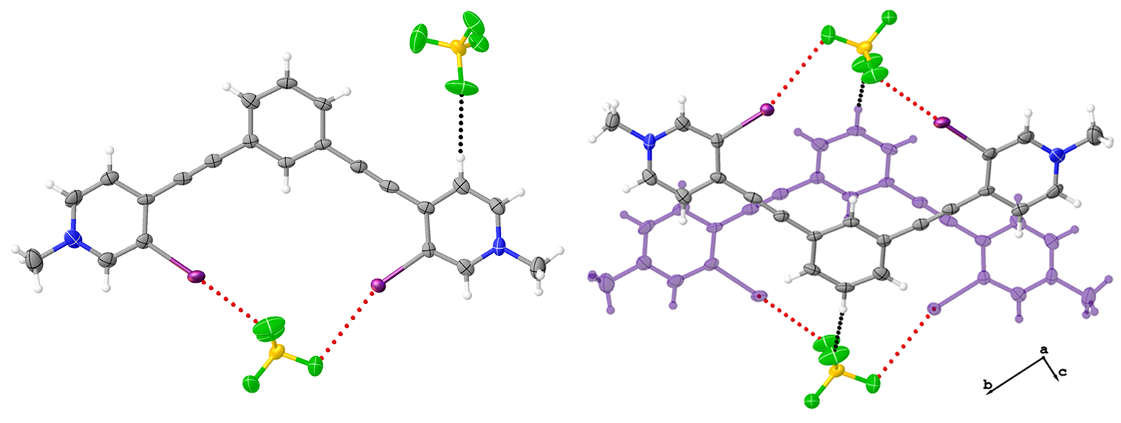
Diffraction quality crystals of 2 were grown by vapor diffusion of diethyl ether into an acetonitrile/methanol solution of 4 and tetra-n-butylammonium hydrogen sulfate resulting in colorless rods. 2 crystalizes in the I2/a space group with one receptor, and two hydrogen sulfate anions. The receptor adopts the W conformation resulting in two monodentate halogen bond interactions, one to each hydrogen sulfate anion (Figure 3) The two halogen bond distances and angles are C-I···O (I1∙∙∙O1) 3.005(5) Å (0.848 RIO) 167.99(14)° and C-I···O (I2∙∙∙O8) 3.244(13) Å (0.916 RIO) 169.1(3)°. The receptor is more planar than 1 as the angles between planes formed by the pyridiniums and benzene core are 6.14° and 8.77°.
One of the anions is disordered and is modeled over two sites (approx. 74:26). Unfortunately, the hydrogen atoms on the hydrogen sulfate anions were unable to be located. Contributing to this difficulty are channels of unidentified solvent molecules that propagate in the crystallographic a direction. The packing of receptors results in two types of dimers that also propagate in the crystallographic a direction. A centered parallel dimer is slightly offset and twisted (Figure 3) and is unique to structure 2 as it is not observed in any of the other reported structures. Off-center antiparallel dimers, where the benzene cores are located near pyridinium cores, result in a benzene centroid—pyridinium centroid distance of 3.589(3) Å. The off-centered antiparallel dimer motif is widely observed in our other reported 1,3-bis(4-ethynyl-3-iodopyridinium)-benzene structures with different anions, triflate (4) thiocyanate (both methanol and dichloromethane solvates), triiodide and chloride (vide infra). Columns of dimers, as well as adjacent columns, are held together by an extensive network of C-H hydrogen bonding and anion–arene contacts with the hydrogen sulfate anions. These contacts are highlighted by evaluating the Hirshfeld surface shown in Figure 4. The hydrogen bonds (C-H···O) range in distance from 2.28 Å to 2.49 Å with angles from 162° to 134°. The closest anion-arene contact is 3.055(6) Å (C1···O4) while the other close contact is 2.891(5) Å from the centroid of a pyridinium ring.
3.1.3. Analysis of 3•MeOH
Diffraction quality crystals of 3•MeOH were grown by vapor diffusion of diethyl ether into an acetonitrile/methanol solution of 1 and tetra-n-butylammonium nitrate, producing colorless rods. 3•MeOH crystalizes in the space group P
with one receptor, two nitrate anions, and a methanol solvent molecule. The receptor adopts the bidentate conformation with both iodine halogen bond donors converging on a single oxygen atom of a nitrate anion with distances and angles of C-I···O (I2∙∙∙O1) 2.903(3) Å (0.8200 RIO), 176.16(13)° and C-I···O (I1∙∙∙O1) 2.965(3) Å (0.8375 RIO), 175.19(14)°. The nitrate is disordered and modeled over two sites (approx. 75:25). The nitrate in the binding pocket is significantly out of planarity with the receptor, which is likely due to favorable C-H hydrogen bonding and anion–arene contacts that the other oxygens make with three other neighboring receptors. The receptor is only slightly more planar than 1, as the angles between planes formed by the pyridiniums and benzene core are 9.91° and 12.05°. The other nitrate interacts with the scaffold through C-H hydrogen bonding and exhibits disorder over two positions (approx. 58:42). This nitrate also accepts a hydrogen bond from the methanol, with an O···O (O7∙∙∙O4) distance of 2.935(7) Å and an O-H···O angle of 149(6)° (Figure 5).
Despite the different trigonal planar geometry of the nitrate anion, and the presence of a methanol molecule, the packing features of 3•MeOH and 1 are strikingly similar. The formation of centered antiparallel dimers (Figure 5) were observed and these assembled into columns propagating in the crystallographic a direction. (Figure 6). Adjacent columns in 3•MeOH arrange in a lamellar motif whereas columns of 1 adopt a herringbone packing arrangement. The columns of dimers and adjacent columns are held together by a network of C-H hydrogen bonding and anion-arene contacts. The Hirshfeld surface shown in Figure 6 highlights these contacts. The hydrogen bonds (C-H···O) range in distance from 2.31 Å to 2.50 Å with angles from 136° to 168°. The closest anion-arene contacts are found to be 2.883(6) Å (O3···N2) and 2.891(5) Å (O4···N1).
3.2. Influence of Anion on Packing Features
Using guidelines established by Custelcean, the structural role of the anions can be assigned to one or multiple categories; spectator, structure-directing, building unit, and secondary building unit [7]. In this family of halogen bonding systems the anion is found primarily as a building unit, which is defined by Custelcean as the anion that directly participates as a structural component to framework assembly through the formation of well-defined and directional interactions. In the cases outlined, the anions participate in extensive halogen bonding, C-H hydrogen bonding, and anion-arene contacts, supporting the construction of the crystal lattice by linking together individual aryl ethynyl units through well-defined interactions.
In our 1,3-bis(4-ethynyl-3-iodopyridinium)-benzene systems, two types of antiparallel dimers are frequently observed; centered and off-centered. The centered antiparallel dimer, shown in 1 and 3•MeOH (Figure 1 and Figure 5), is primarily observed in structures adopting the bidentate conformation. The one exception is an S conformation with the thiocyanate anion dichloromethane solvate structure that exhibits both centered and off-centered antiparallel dimers [38].
A previously reported bidentate chloride structure in this series is solvent free, providing insight into the impact of methanol on the packing [39]. This chloride structure adopts the centered antiparallel dimer, although columns of dimers as in 1 and 3•MeOH, are not present. This is in part due to distortion of the centered antiparallel dimer (Figure 7), which enables the subsequent formation of an off-centered antiparallel dimer, linking the ‘slipped’ centered dimers together (Figure 7).
Another previously reported bidentate species demonstrating the slipped centered antiparallel dimer is a 4•DMF structure [38]. The dimethylformamide resides in the bidentate pocket accepting two halogen bonds and appears to inhibit the formation of a more centered antiparallel dimer due to methyl groups that are unable to accept C-H hydrogen bonds from the dication. In contrast to the chloride species, the packing of 4•DMF results in columns of slipped centered antiparallel receptors propagating in the crystallographic c direction, therefore the off-centered antiparallel dimer is absent. The data suggests that if a bidentate conformation is present, it will be accompanied by a centered antiparallel motif.
The off-centered antiparallel dimer is the most frequently observed dimer; it was present in structures with all three conformations (Scheme 1) as well as with anions of different size and shape. The widespread observance of the antiparallel dimer suggests a favorable arrangement between dimer components and anions. In several cases this dimer is supported by halogen and hydrogen bonding (from separate receptors) with anions spanning the dimer (Figure 8). This frequent observation further supports the classification of anions as building units in these crystals.
We have identified the packing tendencies of these receptors, yet an alternative explanation for the regularity of dimers could be attributed to molecular shape and close-packing, inspired by the classic concepts and ideas of Kitaigorodskii [59,60]. These 1,3-bis(4-ethynyl-pyridinium)-benzene receptors are planar, rigid, and directional tectons, which limit efficient packing arrangements and increase the probability of dimer formation. If the dicationic receptor geometry influences dimer formation, other cationic arylethynyl systems should exhibit similar packing features.
Our previously reported 1,3-bis(4-ethynyl-pyridinium)-benzene system with varying degrees of alkylation and protonation all highlight the presence of the off-centered antiparallel species apart from a bis-perrhenate species that contains two dichloromethane molecules [61]. Hydrogen bond based bis(2-anilinoethynyl)pyridinium derivatives evaluated by Berryman et al. occasionally exhibit off-centered antiparallel dimers, despite their relative steric bulkiness [62]. Interestingly, Johnson and coworkers recently investigated a bidentate halogen bonding system inspired by our work. Their 3,5-bis((2-iodophenyl)ethynyl)pyridinium scaffolds have a single formal charge and methanesulfonyl groups on the outer aryl units [63]. Here, slipped antiparallel centered and off-centered dimers were observed for bidentate and W conformations, respectively. These dimers are reinforced by C-H hydrogen bonding not to anions, but to oxygens of an adjacent receptor. Two other structures that they reported display the S conformation and result in columns of parallel receptors reinforced by intermolecular XBs from the iodine donor to a methanesulfonyl oxygen. Taken together, we see that small changes in the arylethynyl scaffolds can lead to slightly different packing. However, dimer or slip-stack packing is persistent, suggesting that the larger cation and π-π interactions significantly influence the resulting solid-state packing [64]. Also, the frequency of anions supporting the formation of dimers by accepting contacts from each unit of the dimer highlights its common role as a building unit. As our lab begins to diversify the building blocks of these halogen bond systems, we will continue to evaluate how structural changes of the dication receptor influence the dimer formation of these systems.
4. Conclusions
We have presented three new structures of a dicationic 1,3-bis(4-ethynyl-3-iodopyridinium)-benzene halogen bonding receptor with tetrafluoroborate, nitrate, and hydrogen sulfate. Complex 1 adopts a bidentate structure and contains relatively rare halogen bonds to fluorine and boron atoms of a tetrafluoroborate anion. An initial CSD search suggests halogen bonds, by a geometric definition, to boron atoms are rare and likely occur by virtue of proximity to another halogen bond acceptor. Structure 2 adopts the W conformation resulting in a novel centered parallel dimer. 3•MeOH adopts the bidentate conformation and displays centered antiparallel dimers like 1, despite the different anion shape and presence of a solvent molecule. However, differences in packing of 1 and 3•MeOH appear in the arrangement of the dimer columns, where 1 adopts a herringbone arrangement and 3•MeOH resembles a lamellar motif.
The role of the anions in the family of dicationic 1,3-bis(4-ethynyl-3-iodopyridinium)-benzene halogen bonding receptors is primarily as a building unit. Assessment of these structures from a crystal engineering viewpoint has revealed the widespread formation of antiparallel dimers. These dimers can be further categorized into two types: centered and off-centered. The centered species is most often observed when the receptor adopts the bidentate conformation, although a bidentate conformation does not negate the copresence of an off-centered antiparallel dimer as demonstrated by a chloride structure. The off-centered antiparallel dimer is observed with all three planar conformations, and with geometrically diverse anions. Although the anion serves as a building unit in these halogen bond complexes, the molecular shape of the receptors may also influence the packing trends observed. The directionality, rigidity, and favorable planar conformations of aryl ethynyl species can limit efficient packing motifs, conceivably increasing the prospect of dimer formation. As arylethynyl species have enjoyed widespread success in various supramolecular fields, we hope to expand their success in the design of functional multicomponent crystals.
Supplementary Materials
The following are available online at https://0-www-mdpi-com.brum.beds.ac.uk/2073-4352/9/10/522/s1, Table S1. Compiled Dimer Classification of 1,3-bis(4-ethynyl-3-iodopyridinium)-benzene Halogen Bond Donors. Figure S1. Complex 1 with atomic numbering scheme. Thermal ellipsoids drawn at the 50% probability level. Anion disorder omitted for clarity. Figure S2. Complex 2 with atomic numbering scheme. Thermal ellipsoids drawn at the 50% probability level. Anion disorder omitted for clarity. Figure S3. Complex 3•MeOH with atomic numbering scheme. Thermal ellipsoids drawn at the 50% probability level. Anion disorder omitted for clarity.
Author Contributions
D.A.D. provided conceptualization, crystallographic analysis and was the principle author of the paper. A.M.S.R. synthesized and crystalized the compounds, and provided editorial assistance. O.B.B. provided inspiration, supervision, funding, project administration, manuscript review and editing.
Funding
This work was funded by the National Science Foundation (NSF) CAREER CHE-1555324, the Center for Biomolecular Structure and Dynamics CoBRE (NIH NIGMS grant P20GM103546), and the University of Montana (UM). The X-ray crystallographic data were collected using a Bruker D8 Venture, principally supported by NSF MRI CHE-1337908.
Conflicts of Interest
The authors declare no conflict of interest.
References
- Evans, N.H.; Beer, P.D. Advances in Anion Supramolecular Chemistry: From Recognition to Chemical Applications. Angew. Chem. Int. Ed. 2014, 53, 11716–11754. [Google Scholar] [CrossRef] [PubMed] [Green Version]
- Beer, P.D.; Gale, P.A. Anion Recognition and Sensing: The State of the Art and Future Perspectives. Angew. Chem. Int. Ed. 2001, 40, 486–516. [Google Scholar] [CrossRef]
- Gale, P.A.; Howe, E.N.W.; Wu, X. Anion Receptor Chemistry. Chem. Commun. 2016, 1, 351–422. [Google Scholar] [CrossRef] [Green Version]
- Gale, P.A.; Davis, J.T.; Quesada, R. Anion transport and supramolecular medicinal chemistry. Chem. Soc. Rev. 2017, 46, 2497–2519. [Google Scholar] [CrossRef] [PubMed] [Green Version]
- Zhao, J.; Yang, D.; Yang, X.J.; Wu, B. Anion coordination chemistry: From recognition to supramolecular assembly. Coord. Chem. Rev. 2019, 378, 415–444. [Google Scholar] [CrossRef]
- Vilar, R. Anion-Templated Synthesis. Angew. Chem. Int. Ed. 2003, 42, 1460–1477. [Google Scholar] [CrossRef]
- Custelcean, R. Anions in crystal engineering. Chem. Soc. Rev. 2010, 39, 3675. [Google Scholar] [CrossRef]
- Karimi-Jafari, M.; Padrela, L.; Walker, G.M.; Croker, D.M. Creating Cocrystals: A Review of Pharmaceutical Cocrystal Preparation Routes and Applications. Cryst. Growth Des. 2018, 18, 6370–6387. [Google Scholar] [CrossRef]
- Bolla, G.; Nangia, A. Pharmaceutical cocrystals: Walking the talk. Chem. Commun. 2016, 52, 8342–8360. [Google Scholar] [CrossRef] [PubMed]
- Huang, Y.; Wang, Z.; Chen, Z.; Zhang, Q. Organic Cocrystals: Beyond Electrical Conductivities and Field-Effect Transistors (FETs). Angew. Chem. Int. Ed. 2019, 2–18. [Google Scholar]
- Zhang, C.; Xiong, Y.; Jiao, F.; Wang, M.; Li, H. Redefining the Term of “Cocrystal” and Broadening Its Intention. Cryst. Growth Des. 2019, 19, 1471–1478. [Google Scholar] [CrossRef]
- Gryl, M.; Kozieł, M.; Stadnicka, K.M. A proposal for coherent nomenclature of multicomponent crystals. Acta Crystallogr. Sect. B 2019, 75, 53–58. [Google Scholar] [CrossRef] [Green Version]
- Grothe, E.; Meekes, H.; Vlieg, E.; ter Horst, J.H.; de Gelder, R. Solvates, Salts, and Cocrystals: A Proposal for a Feasible Classification System. Cryst. Growth Des. 2016, 16, 3237–3243. [Google Scholar] [CrossRef] [Green Version]
- Cruz-Cabeza, A.J. Acid–base crystalline complexes and the pKa rule. Cryst. Eng. Comm. 2012, 14, 6362. [Google Scholar] [CrossRef]
- Lieffrig, J.; Jeannin, O.; Frąckowiak, A.; Olejniczak, I.; Świetlik, R.; Dahaoui, S.; Aubert, E.; Espinosa, E.; Auban-Senzier, P.; Fourmigué, M. Charge-Assisted Halogen Bonding: Donor-Acceptor Complexes with Variable Ionicity. Chem. Eur. J. 2013, 19, 14804–14813. [Google Scholar] [CrossRef] [PubMed]
- Walter, S.M.; Kniep, F.; Rout, L.; Schmidtchen, F.P.; Herdtweck, E.; Huber, S.M. Isothermal Calorimetric Titrations on Charge-Assisted Halogen Bonds: Role of Entropy, Counterions, Solvent, and Temperature. J. Am. Chem. Soc. 2012, 134, 8507–8512. [Google Scholar] [CrossRef] [PubMed]
- Desiraju, G.R.; Ho, P.S.; Kloo, L.; Legon, A.C.; Marquardt, R.; Metrangolo, P.; Politzer, P.; Resnati, G.; Rissanen, K. Definition of the halogen bond (IUPAC Recommendations 2013). Pure Appl. Chem. 2013, 85, 1711–1713. [Google Scholar] [CrossRef]
- Brown, A.; Beer, P.D. Halogen bonding anion recognition. Chem. Commun. 2016, 52, 8645–8658. [Google Scholar] [CrossRef] [PubMed]
- Cavallo, G.; Metrangolo, P.; Milani, R.; Pilati, T.; Priimagi, A.; Resnati, G.; Terraneo, G. The Halogen Bond. Chem. Rev. 2016, 116, 2478–2601. [Google Scholar] [CrossRef] [PubMed] [Green Version]
- Tepper, R.; Schubert, U.S. Halogen Bonding in Solution: Anion Recognition, Templated Self-Assembly, and Organocatalysis. Angew. Chem. Int. Ed. 2018, 57, 6004–6016. [Google Scholar] [CrossRef]
- Rowe, R.K.; Ho, P.S. Relationships between hydrogen bonds and halogen bonds in biological systems. Acta Crystallogr. Sect. B 2017, 73, 255–264. [Google Scholar] [CrossRef] [PubMed]
- Auffinger, P.; Hays, F.A.; Westhof, E.; Ho, P.S. Halogen bonds in biological molecules. Proc. Natl. Acad. Sci. USA 2004, 101, 16789–16794. [Google Scholar] [CrossRef] [PubMed] [Green Version]
- Kniep, F.; Jungbauer, S.H.; Zhang, Q.; Walter, S.M.; Schindler, S.; Schnapperelle, I.; Herdtweck, E.; Huber, S.M. Organocatalysis by Neutral Multidentate Halogen-Bond Donors. Angew. Chem. Int. Ed. 2013, 52, 7028–7032. [Google Scholar] [CrossRef] [PubMed]
- Walter, S.M.; Kniep, F.; Herdtweck, E.; Huber, S.M. Halogen-Bond-Induced Activation of a Carbon-Heteroatom Bond. Angew. Chem. Int. Ed. 2011, 50, 7187–7191. [Google Scholar] [CrossRef] [PubMed]
- Jungbauer, S.H.; Huber, S.M. Cationic Multidentate Halogen-Bond Donors in Halide Abstraction Organocatalysis: Catalyst Optimization by Preorganization. J. Am. Chem. Soc. 2015, 137, 12110–12120. [Google Scholar] [CrossRef] [PubMed]
- Dumele, O.; Schreib, B.; Warzok, U.; Trapp, N.; Schalley, C.A.; Diederich, F. Halogen-Bonded Supramolecular Capsules in the Solid State, in Solution, and in the Gas Phase. Angew. Chem. Int. Ed. 2017, 56, 1152–1157. [Google Scholar] [CrossRef] [PubMed]
- Dumele, O.; Trapp, N.; Diederich, F. Halogen Bonding Molecular Capsules. Angew. Chem. Int. Ed. 2015, 54, 12339–12344. [Google Scholar] [CrossRef] [PubMed]
- Beyeh, N.K.; Pan, F.; Rissanen, K. A Halogen-Bonded Dimeric Resorcinarene Capsule. Angew. Chem. 2015, 127, 7411–7415. [Google Scholar] [CrossRef]
- Massena, C.J.; Wageling, N.B.; Decato, D.A.; Martin Rodriguez, E.; Rose, A.M.; Berryman, O.B. A Halogen-Bond-Induced Triple Helicate Encapsulates Iodide. Angew. Chem. Int. Ed. 2016, 55, 12398–12402. [Google Scholar] [CrossRef]
- Massena, C.J.; Decato, D.A.; Berryman, O.B. A long-lived Halogen-Bonding anion triple helicate accommodates rapid guest exchange. Angew. Chem. Int. Ed. 2018, 57, 16109–16113. [Google Scholar] [CrossRef] [PubMed]
- Metrangolo, P.; Pilati, T.; Terraneo, G.; Biella, S.; Resnati, G. Anion coordination and anion-templated assembly under halogen bonding control. Cryst. Eng. Comm. 2009, 11, 1187. [Google Scholar] [CrossRef]
- Cavallo, G.; Metrangolo, P.; Pilati, T.; Resnati, G.; Sansotera, M.; Terraneo, G. Halogen bonding: A general route in anion recognition and coordination. Chem. Soc. Rev. 2010, 39, 3772. [Google Scholar] [CrossRef] [PubMed]
- Carroll, C.N.; Naleway, J.J.; Haley, M.M.; Johnson, D.W. Arylethynyl receptors for neutral molecules and anions: Emerging applications in cellular imaging. Chem. Soc. Rev. 2010, 39, 3875. [Google Scholar] [CrossRef] [PubMed]
- Vonnegut, C.L.; Tresca, B.W.; Johnson, D.W.; Haley, M.M. Ion and Molecular Recognition Using Aryl-Ethynyl Scaffolding. Chem. Asian J. 2015, 10, 522–535. [Google Scholar] [CrossRef] [PubMed]
- Leininger, S.; Olenyuk, B.; Stang, P.J. Self-Assembly of discrete cyclic nanostructures mediated by transition metals. Chem. Rev. 2000, 100, 853–908. [Google Scholar] [CrossRef]
- Massena, C.J.; Riel, A.M.S.; Neuhaus, G.F.; Decato, D.A.; Berryman, O.B. Solution and solid-phase halogen and C-H hydrogen bonding to perrhenate. Chem. Commun. 2015, 51, 1417–1420. [Google Scholar] [CrossRef] [PubMed]
- Sun, J.; Riel, A.M.S.; Berryman, O.B. Solvatochromism and fluorescence response of a halogen bonding anion receptor. New J. Chem. 2018, 42, 10489–10492. [Google Scholar] [CrossRef]
- Riel, A.M.S.; Jessop, M.J.; Decato, D.A.; Massena, C.J.; Nascimento, V.R.; Berryman, O.B. Experimental investigation of halogen-bond hard-soft acid-base complementarity. Acta Crystallogr. Sect. B 2017, 73, 203–209. [Google Scholar] [CrossRef]
- Riel, A.M.S.; Decato, D.A.; Sun, J.; Massena, C.J.; Jessop, M.J.; Berryman, O.B. The intramolecular hydrogen bonded-halogen bond: A new strategy for preorganization and enhanced binding. Chem. Sci. 2018, 9, 5828–5836. [Google Scholar] [CrossRef]
- Sheldrick, G.M. SADABS: Area Detector Absorption Correction; University of Gottingen: Alemanha, Germany, 1996. [Google Scholar]
- Dolomanov, O.V.; Bourhis, L.J.; Gildea, R.J.; Howard, J.A.K.; Puschmann, H. OLEX2: A complete structure solution, refinement and analysis program. J. Appl. Crystallogr. 2009, 42, 339–341. [Google Scholar] [CrossRef]
- Sheldrick, G.M. SHELXT—Integrated space-group and crystal-structure determination. Acta Crystallogr. Sect. A Found. Crystallogr. 2015, 71, 3–8. [Google Scholar] [CrossRef] [PubMed]
- Sheldrick, G.M. Crystal structure refinement with SHELXL. Acta Crystallogr. Sect. C Struct. Chem. 2015, 71, 3–8. [Google Scholar] [CrossRef] [PubMed]
- Bruker, APEX2; Bruker AXS Inc: Madison, WI, USA, 2007.
- Sheldrick, G.M. A short history of SHELX. Acta Crystallogr. Sect. A Found. Crystallogr. 2008, 64, 112–122. [Google Scholar] [CrossRef] [PubMed]
- Spek, A.L. PLATON SQUEEZE: A tool for the calculation of the disordered solvent contribution to the calculated structure factors. Acta Crystallogr. Sect. C Struct. Chem. 2015, 71, 9–18. [Google Scholar] [CrossRef] [PubMed]
- Spek, A.L. Structure validation in chemical crystallography. Acta Crystallogr. Sect. D Biol. Crystallogr. 2009, 65, 148–155. [Google Scholar] [CrossRef] [PubMed]
- Bruno, I.J.; Cole, J.C.; Edgington, P.R.; Kessler, M.; Macrae, C.F.; Mccabe, P.; Pearson, J.; Taylor, R. Structural Science New software for searching the Cambridge Structural Database and visualizing crystal structures. Acta Cryst. 2002, 58, 389–397. [Google Scholar] [CrossRef] [PubMed]
- Groom, C.R.; Bruno, I.J.; Lightfoot, M.P.; Ward, S.C. The Cambridge structural database. Acta Crystallogr. Sect. B Struct. Sci. Cryst. Eng. Mater. 2016, B72, 171–179. [Google Scholar] [CrossRef] [PubMed]
- Wolff, S.K.; Grimwood, D.J.; McKinnon, J.J.; Turner, M.J.; Jayatilaka, D.; Spackman, M.A. CrystalExplorer (Version 3.1); University of Western Australia: Crawley, Austrália, 2012. [Google Scholar]
- Spackman, M.A.; Byrom, P.G. A novel definition of a molecule in a crystal. Chem. Phys. Lett. 1997, 267, 215–220. [Google Scholar] [CrossRef]
- Spackman, M.A.; Jayatilaka, D. Hirshfeld surface analysis. CrystEngComm 2009, 11, 19–32. [Google Scholar] [CrossRef]
- Alvarez, S. A cartography of the van der Waals territories. Dalt. Trans. 2013, 42, 8617. [Google Scholar] [CrossRef]
- Sirohiwal, A.; Hathwar, V.R.; Dey, D.; Regunathan, R.; Chopra, D. Characterization of fluorine-centred ‘F...O’ σ-hole interactions in the solid state. Acta Crystallogr. Sect. B 2017, 73, 140–152. [Google Scholar] [CrossRef] [PubMed]
- Dikundwar, A.G.; Row, T.N.G. Evidence for the “Amphoteric” Nature of Fluorine in Halogen Bonds: An Instance of Cl···F Contact. Cryst. Growth Des. 2012, 12, 1713–1716. [Google Scholar] [CrossRef]
- Metrangolo, P.; Murray, J.S.; Pilati, T.; Politzer, P.; Resnati, G.; Terraneo, G. The fluorine atom as a halogen bond donor, viz. a positive site. Cryst. Eng. Comm. 2011, 13, 6593. [Google Scholar] [CrossRef]
- Alkorta, I.; Elguero, J.; Del Bene, J.E. Boron as an Electron-Pair Donor for B…Cl Halogen Bonds. Chem. Phys. Chem. 2016, 17, 3112–3119. [Google Scholar] [CrossRef]
- Zhuo, H.; Yu, H.; Li, Q.; Li, W.; Cheng, J. Some measures for mediating the strengths of halogen bonds with the B-B bond in diborane(4) as an unconventional halogen acceptor. Int. J. Quantum Chem. 2014, 114, 128–137. [Google Scholar] [CrossRef]
- Kitaigoradskii, A.I. Organic Chemical Crystallography; Consultants Bureau: New York, NY, USA, 1961. [Google Scholar]
- Corpinot, M.K.; Bučar, D.K. A Practical Guide to the Design of Molecular Crystals. Cryst. Growth Des. 2019, 19, 1426–1453. [Google Scholar] [CrossRef]
- Riel, A.M.S.; Decato, D.A.; Berryman, O.B. Protonation and Alkylation Induced Multidentate C–H···Anion Binding to Perrhenate. Cryst. Growth Des. 2016, 16, 974–980. [Google Scholar] [CrossRef]
- Berryman, O.B.; Johnson, C.A.; Vonnegut, C.L.; Fajardo, K.A.; Zakharov, L.N.; Johnson, D.W.; Haley, M.M. Solid-State Examination of Conformationally Diverse Sulfonamide Receptors Based on Bis(2-anilinoethynyl)pyridine, -Bipyridine, and -Thiophene. Cryst. Growth Des. 2015, 15, 1502–1511. [Google Scholar] [CrossRef] [Green Version]
- Lohrman, J.A.; Deng, C.-L.; Shear, T.A.; Zakharov, L.N.; Haley, M.M.; Johnson, D.W. Methanesulfonyl-polarized halogen bonding enables strong halide recognition in an arylethynyl anion receptor. Chem. Commun. 2019, 55, 1919–1922. [Google Scholar] [CrossRef]
- Molčanov, K.; Milašinović, V.; Kojić-Prodić, B. Contribution of Different Crystal Packing Forces in π-Stacking: From Noncovalent to Covalent Multicentric Bonding. Cryst. Growth Des. 2019, 19, 5967–5980. [Google Scholar] [CrossRef]
Scheme 1.
ChemDraw representations of the three planar conformations obtained by rotating about the alkyne bonds: the bidentate conformation (left), the S conformation (middle), and the W conformation (right).
Scheme 1.
ChemDraw representations of the three planar conformations obtained by rotating about the alkyne bonds: the bidentate conformation (left), the S conformation (middle), and the W conformation (right).

Scheme 2.
Synthesis of 1 including the numbering scheme of other complexes. Synthesis of 2, and 3 are described in the text, while synthesis of 4 and the neutral starting compound was reported previously [36].
Scheme 2.
Synthesis of 1 including the numbering scheme of other complexes. Synthesis of 2, and 3 are described in the text, while synthesis of 4 and the neutral starting compound was reported previously [36].

Figure 1.
Asymmetric unit of 1 highlighting the bidentate conformation, the halogen bonds (red dotted lines) to the tetrafluoroborate anion, and the C-H hydrogen bonding (black dotted lines) to the tetrafluoroborate anion outside the pocket (upper and lower left). The upper left image shows a top down view while the bottom left image is from the side, highlighting the distortion of the receptor and the halogen bonds to the different fluorine atoms. On the upper right, the packing diagram highlights the dimers formed between two receptors, which result in columns that propagate along the crystallographic a axis. The lower right image highlights the centered antiparallel dimer. Thermal ellipsoids are drawn at the 50% probability level and anion disorder is omitted for clarity.

Figure 2.
Hirshfeld surface map of 1 highlighting the C-H hydrogen bonding contacts and arrangement of tetrafluoroborate anions around the receptor (left). Packing diagram of 1 when viewed down the crystallographic a axis, highlighting the herringbone arrangement of dimer columns (right). Thermal ellipsoids are drawn at the 50% probability level and anion disorder is omitted for clarity.

Figure 3.
Space filling diagram (drawn using van der Walls radii) of the asymmetric unit of 2 (left). Anion disorder omitted for clarity. Thermal ellipsoid diagrams showing the centered parallel dimer of 2 (lower right) and the off-centered antiparallel dimer (upper right). Thermal ellipsoids are drawn at the 50% probability level and anion disorder is omitted for clarity.

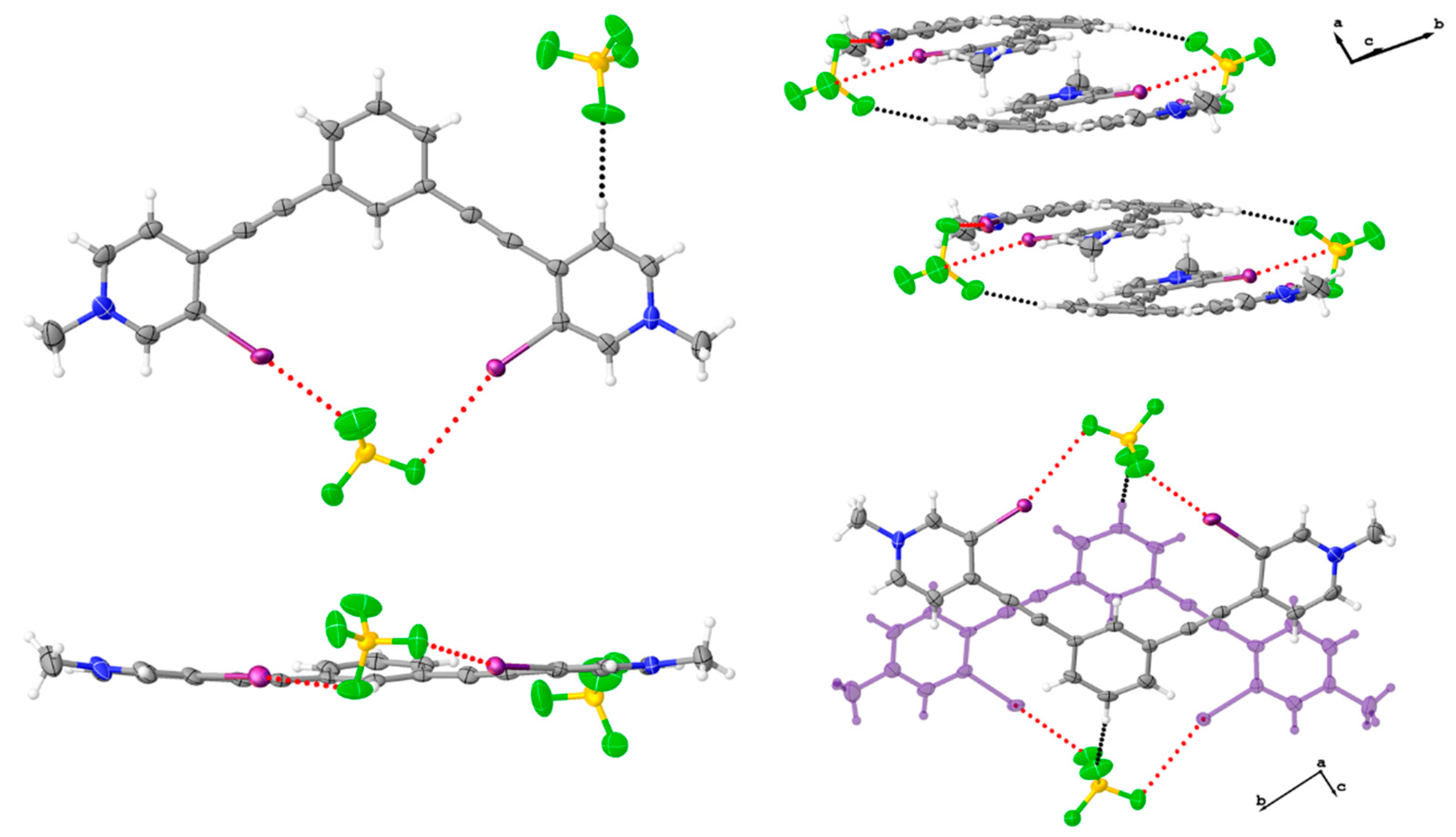
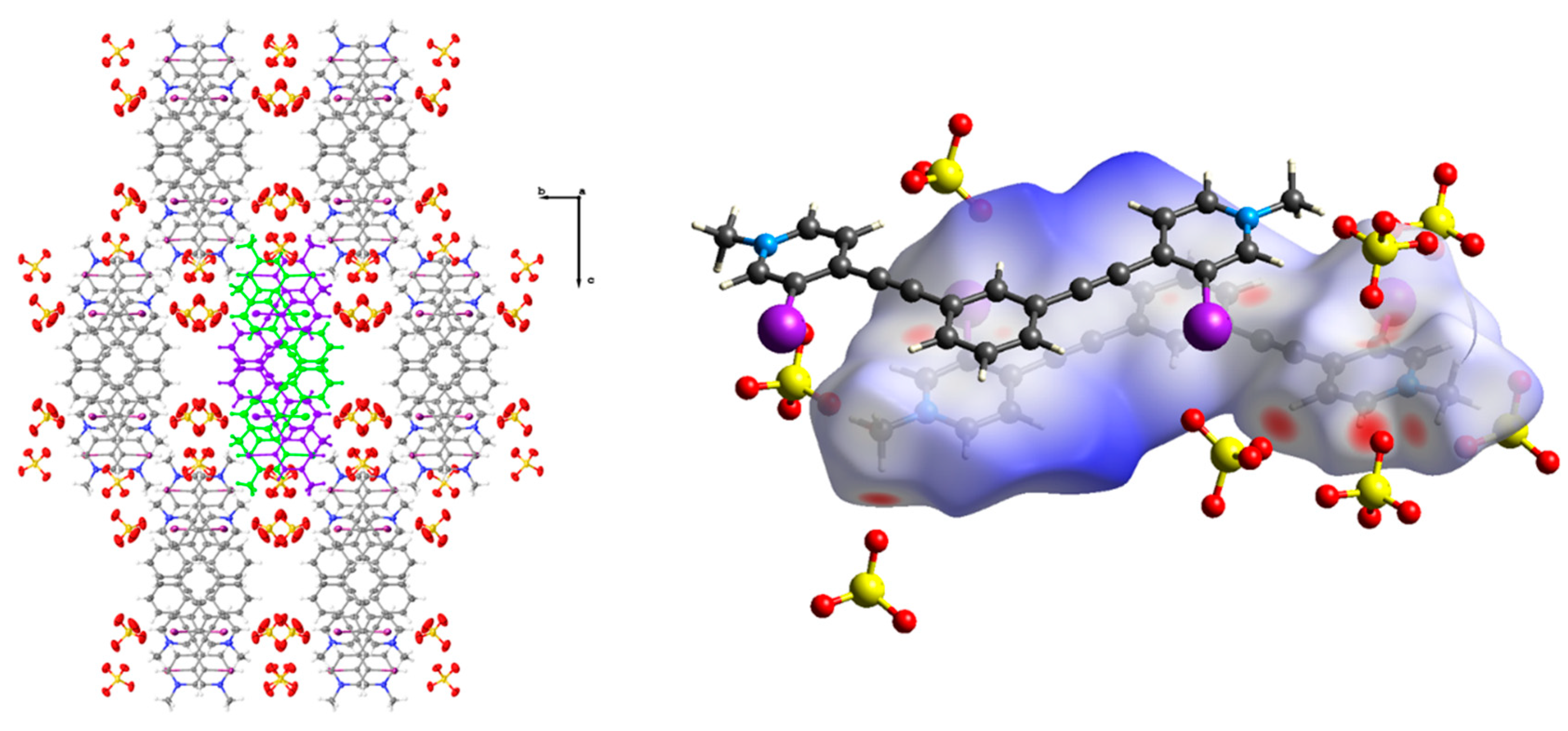
Figure 4.
Packing diagram of 2 when viewed down the crystallographic a axis (left). Anion disorder omitted for clarity, and thermal ellipsoids are drawn at the 50% probability level. Hirshfeld surface map of 2 highlighting the C-H hydrogen bonding contacts and arrangement of hydrogen sulfate anions around the receptor as well as the off-centered antiparallel dimer (right).

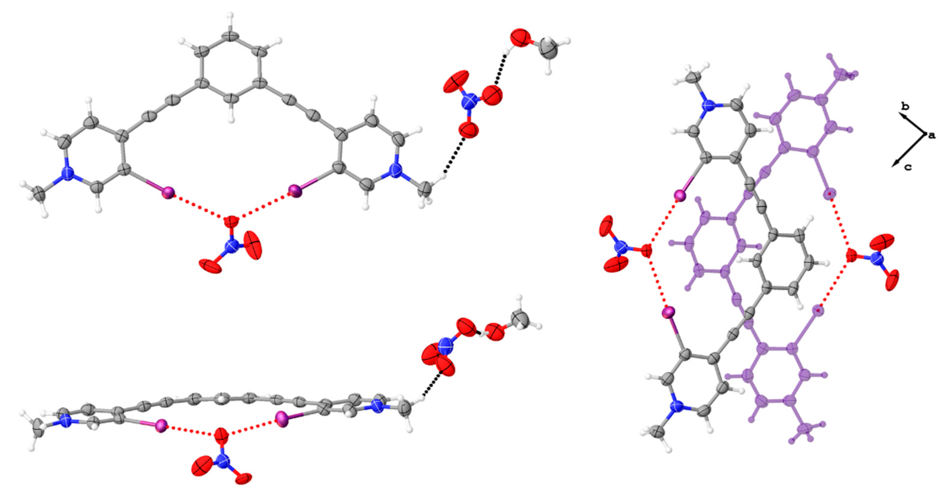
Figure 5.
Asymmetric unit of 3•MeOH highlighting the bidentate conformation, the halogen bonds (red dotted lines) to the nitrate anion, and the hydrogen bonding (black dotted lines) to the nitrate anion outside the pocket (upper and lower left). The upper left image shows a top down view while the bottom left image is from the side, highlighting the convergent halogen bonds to a single oxygen atom. The image to the right highlights the centered antiparallel dimer as viewed down the crystallographic a axis. Thermal ellipsoids drawn at the 50% probability level and anion disorder omitted for clarity.

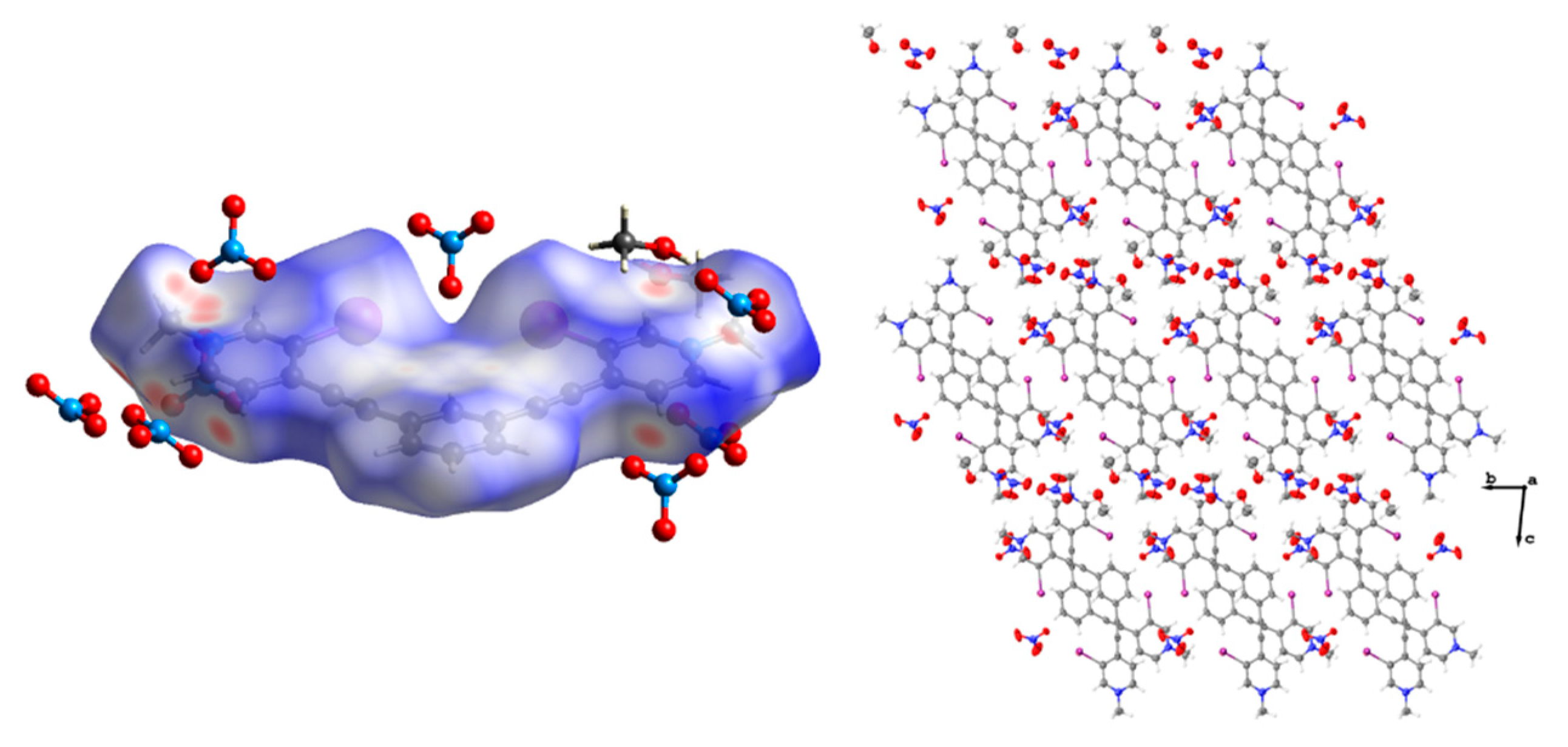
Figure 6.
Hirshfeld surface map of 3•MeOH highlighting the C-H hydrogen bonding contacts and arrangement of nitrate anions and methanol molecules around the receptor (left). Packing diagram of 3•MeOH when viewed down the crystallographic a axis (right). Anion disorder omitted for clarity, and thermal ellipsoids are drawn at the 50% probability level.

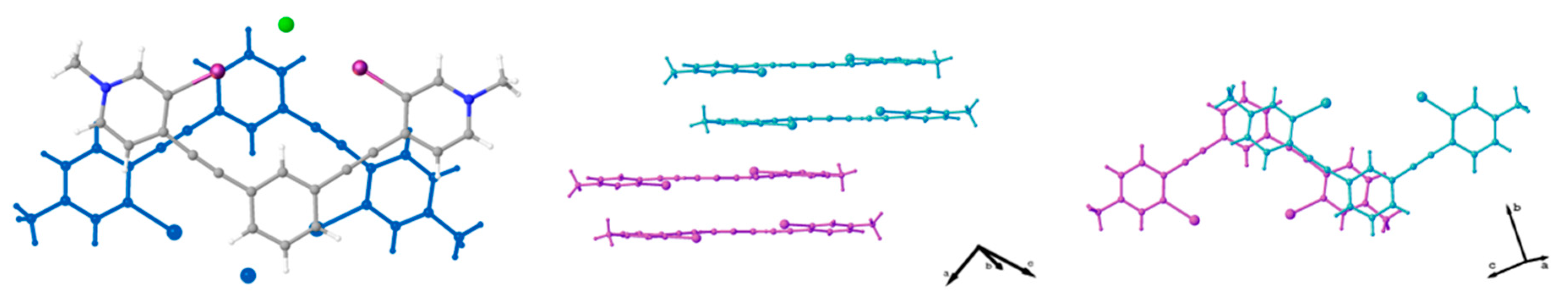
Figure 7.
Ball-and-stick models highlighting the ‘slipped’ centered antiparallel dimer of the chloride structure (left) and arrangement of these slipped dimers to form off-centered antiparallel dimers (center and right).
Figure 7.
Ball-and-stick models highlighting the ‘slipped’ centered antiparallel dimer of the chloride structure (left) and arrangement of these slipped dimers to form off-centered antiparallel dimers (center and right).

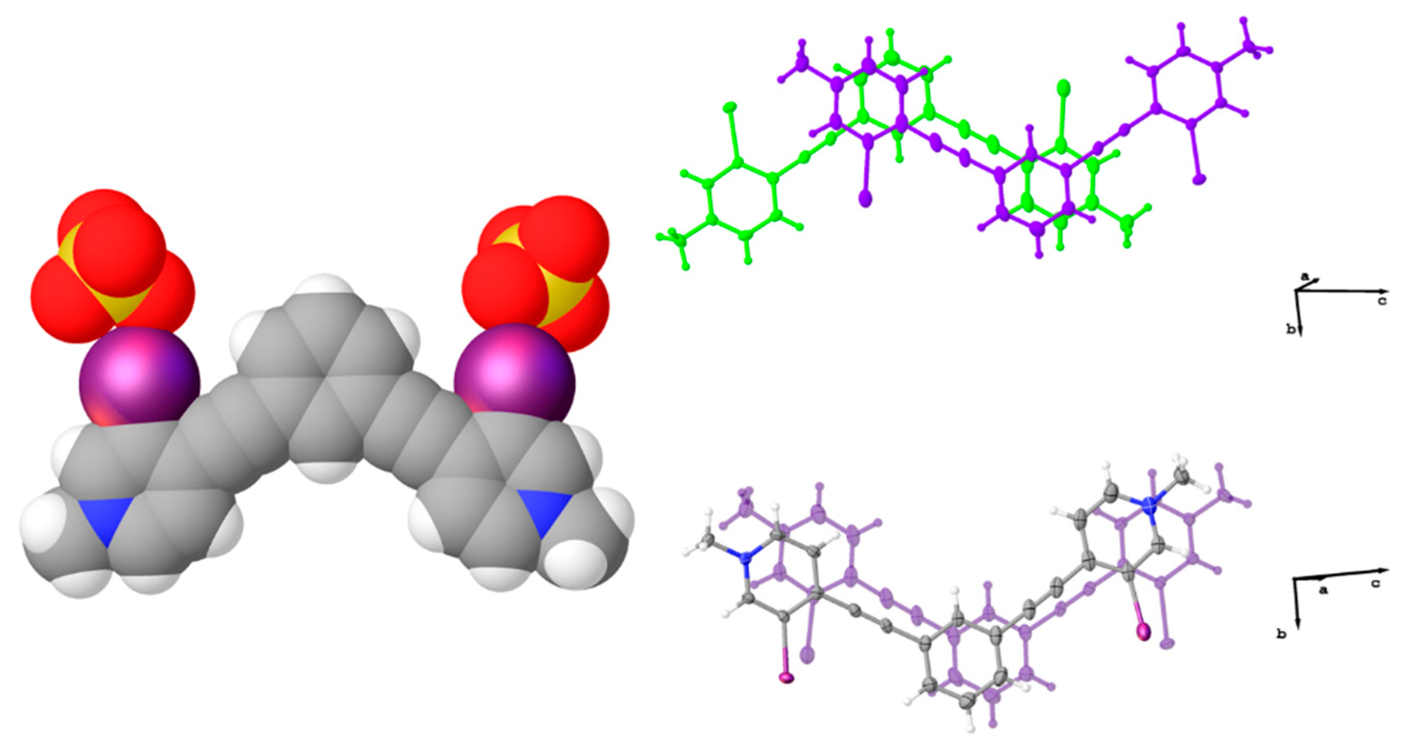
Figure 8.
Diagrams of 2 (left) and previously reported triiodide complex [38] (right) highlighting anions that span the off-centered antiparallel dimers. These anions support the dimer formation through a combination of halogen bonding (red dotted line) and hydrogen bonding (black dotted line).
Figure 8.
Diagrams of 2 (left) and previously reported triiodide complex [38] (right) highlighting anions that span the off-centered antiparallel dimers. These anions support the dimer formation through a combination of halogen bonding (red dotted line) and hydrogen bonding (black dotted line).


Table 1.
X-ray crystallographic parameters.
| Crystal Parameter | 1 | 2 | 3•MeOH |
|---|---|---|---|
| CCDC | 1,936,528 | 1,936,530 | 1,936,529 |
| empirical formula | C22H16B2F8I2N2 | C22H16I2N2O8S2 | C23H20I2N4O7 |
| formula weight | 735.79 | 754.29 | 718.23 |
| temp (K) | 100 | 100 | 150 |
| crystal system | monoclinic | monoclinic | triclinic |
| space group | P21/c | I2/a | P |
| a (Å) | 7.0124(7) | 14.4133(6) | 7.2630(7) |
| b (Å) | 32.096(3) | 12.5563(5) | 11.0928(11) |
| c (Å) | 11.4846(12) | 33.0305(16) | 16.7314(17) |
| α (°) | 90 | 90 | 81.574(3) |
| β (°) | 103.063(2) | 91.905(2) | 77.700(3) |
| γ (°) | 90 | 90 | 78.539(3) |
| V (Å3) | 2517.9(4) | 5974.5(4) | 1283.1(2) |
| Z | 4 | 8 | 2 |
| Dc (g/cm3) | 1.941 | 1.677 | 1.859 |
| μ (mm−1) | 2.572 | 2.288 | 2.501 |
| F (000) | 1400.0 | 2912.0 | 696.0 |
| crystal size (mm) | 0.30 × 0.04 × 0.03 | 0.35 × 0.03 × 0.02 | 0.35 × 0.05 × 0.03 |
| 2Θ max (°) | 50.05 | 52.744 | 54.968 |
| no. of reflections | 33,888 | 106,893 | 42,751 |
| no. of independent reflections | 4444 | 6106 | 5904 |
| Rint | 0.0427 | 0.0454 | 0.0368 |
| GOF | 1.460 | 1.062 | 1.055 |
| R1 (I > 2σ(I)) | 0.0634 | 0.0404 | 0.0335 |
| wR2 (I > 2σ(I)) | 0.1482 | 0.0960 | 0.0801 |
| max/min residual e− density (e Å−3) | 1.62/−1.20 | 2.81/−1.21 | 1.47/−0.55 |
Table 2.
Halogen bond parameters for reported structures.
| Compound | Interaction | C-I···LB Distance (Å) | Reduction Ratio* | C-I···LB Angle (°) |
|---|---|---|---|---|
| 1 | C-I···F (I1-F4) | 3.396(7) | 0.97 | 161.2(3) |
| C-I···F (I2-F1) | 3.100(8) | 0.89 | 173.5(3) | |
| C-I···B (I2-B1) | 3.767(13) | 0.95 | 164.1(3) | |
| 3•MeOH | C-I···O (I2-O1) | 2.903(3) | 0.82 | 176.16(13) |
| C-I···O (I1-O1) | 2.965(3) | 0.84 | 175.19(14) | |
| 2 | C-I···O (I1-O1) | 3.005(5) | 0.85 | 167.99(14) |
| C-I···O (I2-O8) | 3.244(13) | 0.92 | 169.1(3) |
* The reduction ratio is defined as the ratio of the distance measured over the sum of the van der Walls radii. Radii used were obtained from [53] (see Materials and Methods for more details).
© 2019 by the authors. Licensee MDPI, Basel, Switzerland. This article is an open access article distributed under the terms and conditions of the Creative Commons Attribution (CC BY) license (http://creativecommons.org/licenses/by/4.0/).
Share and Cite
MDPI and ACS Style
Decato, D.A.; Riel, A.M.S.; Berryman, O.B. Anion Influence on the Packing of 1,3-Bis(4-Ethynyl-3-Iodopyridinium)-Benzene Halogen Bond Receptors. Crystals 2019, 9, 522. https://0-doi-org.brum.beds.ac.uk/10.3390/cryst9100522
AMA Style
Decato DA, Riel AMS, Berryman OB. Anion Influence on the Packing of 1,3-Bis(4-Ethynyl-3-Iodopyridinium)-Benzene Halogen Bond Receptors. Crystals. 2019; 9(10):522. https://0-doi-org.brum.beds.ac.uk/10.3390/cryst9100522
Chicago/Turabian StyleDecato, Daniel A., Asia Marie S. Riel, and Orion B. Berryman. 2019. "Anion Influence on the Packing of 1,3-Bis(4-Ethynyl-3-Iodopyridinium)-Benzene Halogen Bond Receptors" Crystals 9, no. 10: 522. https://0-doi-org.brum.beds.ac.uk/10.3390/cryst9100522
Note that from the first issue of 2016, this journal uses article numbers instead of page numbers. See further details here.