Article

Numerical Simulation of Temperature and Fluid Fields in Solidification Process of Ferritic Stainless Steel under Vibration Conditions

School of Metallurgical Engineering, Xi’an University of Architecture and Technology, Xi’an 710055, China
*
Author to whom correspondence should be addressed.
Submission received: 22 February 2019 / Revised: 16 March 2019 / Accepted: 21 March 2019 / Published: 25 March 2019
(This article belongs to the Special Issue Nanostructured Ferritic Alloys)

Abstract

:
A three-dimensional model of a circular casting mold with a vibrating nucleus generator was established, and the characteristics of temperature and flow fields during the solidification process of ferritic stainless steel Cr17 in the casting mold were analyzed using finite element and finite difference methods. A standard k-ε turbulent current model was adopted to simulate the temperature field, and a standard k-ε model in Reynolds-averaged Navier–Stokes equations (RANS) was employed to deal with the flow field. The temperature field diffuses outward with a positive temperature gradient. Low degrees of undercooling can prevent solidified shells from forming rapidly on the surface of the nucleus generator. The temperature perpendicular to the direction of vibration is lower than that in the direction of vibration. The flow field exhibits a heart-shaped distribution and spreads gradually outward. The uniform distribution of grains can be achieved at three different frequencies of vibration. The results show that the degree of undercooling affects the distribution of the temperature field while the frequency of vibration affects the flow field significantly. Under the conditions of undercooling of 540 K and vibration frequency of 1000 Hz, the region perpendicular to the vibration direction of the nucleus generator is the optimum area for equiaxed crystal formation.

1. Introduction

As a resource-saving material, ferrite stainless steel may replace the relatively expensive austenitic stainless steel. However, wrinkles and even crack defects that appear during the following plastic forming process reduce the mechanical properties and then restrict the wide application of a ferrite stainless steel rolled sheet.
This is an effective method to improve the forming defects by promoting the formation of equiaxed grains during the solidification process of ferrite stainless steel. In recent years, based on the nucleation theory of solidification process, a new vibration-excited liquid metal nuclear technique has been proposed [1]. A chilling generator with vibration is inserted into a superheated liquid metal, crystals nucleate and grow on the chilling surface of the generator, and the growing grains are stripped and ejected into the melt due to vibration [2]. The grain fragments form the sources of equiaxed nucleation during the subsequent solidification process.
However, the solidification of ferrite stainless steel is a high temperature thermoforming process. The coupling effects of temperature and flow field are very important for the formation and growth of equiaxed grains during solidification. However, it is difficult to obtain scientific results through real-time observation and measurement [3,4]. Therefore, the numerical simulation of temperature and flow field in the solidification process is of great significance [5].
Since 1962, when Fursund [6] first used computer simulation of the casting temperature field, the numerical simulation technology of the casting process has made great progress. Kuo [7] designed a method of cutting castings from investment casting trees by the vibration method. Lyubimov et al. [8] and Lyubimova et al. [9] used numerical simulation to study the effect of small amplitude and high frequency rotational vibration on the directional crystallization of binary alloys. Numerical simulation of vibration-induced liquid metal nucleation during the solidification process of ferrite stainless steel has not been reported. Su et al. [10] used the finite element method to simulate the temperature field of the copper-clad aluminum bar horizontal continuous casting process and determined the reasonable process parameters. Ko et al. [11] solved the heat conduction equation by a numerical method, analyzed the heat transfer behavior of the mold wall, and optimized the cooling process of the crystallizer. Yun et al. [12] modeled and analyzed the continuous casting process of die steel by mixed Lagrangian and Euler numerical methods, simulating the temperature distribution, melt flow, shell thickness, and stress distribution. Numerical simulation of vibration-induced liquid metal nucleation during the solidification process of ferrite stainless steel has not been reported.
In this paper, the Fluent module of ANSYS software was used to simulate the solidification process of ferritic stainless steel Cr17 under vibration conditions. The distributions of temperature and flow fields were obtained. The temperature gradient in the solidification front as well as the fluid flow rate and flow trajectory in the solid–liquid two-phase region have been analyzed [13,14,15], and the behaviors of nucleation, grain detachment under different undercooling, and vibration frequency were also briefly discussed.

2. Mathematical Model

2.1. Fundamental Equations

Every flow problem must satisfy the continuity equation. The physical meaning of this is that the increase in the mass of the control unit is equal to the mass of the other control units flowing into the control unit. The continuity equations for the fluid flow are given as follows [16]:
ρ t + ( ρ u x ) x + ( ρ u y ) y + ( ρ u z ) z = 0
ρ t + ( ρ u ) = 0 .
The flow of liquid metal can be defined as the unsteady flow of the incompressible viscous fluid in this paper. The density of the liquid metal changes with temperature, and the temperature is a function of time, so the density of the liquid metal changes with time. In this work, since the density of the liquid metal does not change significantly with time, the density of the liquid metal is set to a certain value, so that the value of ρ t is 0. The continuity equation can be simplified as follows:
( ρ u x ) x + ( ρ u y ) y + ( ρ u z ) z = 0
where u x , u y , and u z ( m / s ) are the velocity components in the three directions of x, y, and z, respectively; ρ ( kg / m 3 ) and t ( s ) are the density and times. ▽ is the vector differential operator. = x i + y j + z k .
For a given fluid micro-element, the rate of change of momentum versus time is equal to the sum of the various forces acting on the fluid micro-element, which is the momentum equation. The system can be simulated by the mathematical expressions as follows:
ρ ( u x t + u x u x x + u y u y y + u z u z z ) = P x + p g x + μ ( 2 u x x 2 + 2 u x y 2 + 2 u x z 2 )
ρ ( u y t + u x u y x + u y u y y + u z u y z ) = P y + p g y + μ ( 2 u y x 2 + 2 u y y 2 + 2 u y z 2 )
ρ ( u z t + u x u z x + u y u z y + u z u z z ) = P z + p g z + μ ( 2 u z x 2 + 2 u z y 2 + 2 u z z 2 )
where P ( Pa ) is the pressure of the fluid, μ ( Pas ) is the dynamic viscosity, and g ( m / s 2 ) is the acceleration of gravity. The structure of the above mathematical expressions can be understood as: I n e r t i a   f o r c e = p r e s s u r e + g r a v i t y + v i s c o u s . Its essence is Newton’s second law. F = m a . m ( kg ) is the mass of the forced object, a ( m / s 2 ) is the acceleration of the forced object, F ( N ) is the resultant force of the forced object.
Heat transfer is the interaction of thermal and hydrodynamic fields [17]. In addition to satisfying the continuity equation and the momentum equation, the flow system with heat exchange must also satisfy the energy equation, which is essentially the first law of thermodynamics. The system can be simulated by the energy equation as follows:
( ρ E ) t + [ u ¯ ( ρ E + P ) ] = · [ k eff T j h j J j + ( τ eff · u ¯ ) ] + S h
where E ( J / kg ) is the total energy of the fluid micro-element, including the sum of the internal energy, kinetic energy, and potential energy E = h P ρ + u 2 2 . Here, h ( J / kg ) is the enthalpy, while h j ( J / kg ) is the enthalpy of component j . Furthermore, h j = T r e f T C p , j d T = C P , j T | T r e f T = C P , j ( T T r e f ) , where T r e f = 298.15   K . k e f f = k + k t . k e f f ( W / ( m · K ) ) is the effective heat transfer coefficient and k t is the turbulent heat transfer coefficient determined according to the turbulence model used. k is the material constant. J j is the diffusion flux of component j .     S h is a chemical heat source and can represent other user-defined volumetric heat source items.
Based on the formulas derived from the thermodynamic parameters of stainless steel in [18], the thermodynamic parameters of Cr17 at a casting temperature of 1813 K were calculated in this paper. The calculation formulas are as follows:
Specific   Heat /   ( J K 1 kg 1 ) :   472 + 13.6 × 10 2 T 2.82 × 10 6 / T 2
Viscosity / ( Pa · s ) : ( 2.396 + 7950 / 1000 T )
Thermal   Conductivity / ( Wm 1 K 1 ) :   25.4 + 1.3 × 10 2 ( T 1000 ) .
The thermodynamic parameters of steel include density, specific heat, thermal conductivity, and initial temperature, as shown in Table 1.

2.2. Simulation Parameters Determination

The temperature field model is an unsteady turbulence model. The velocity field of melt under vibration conditions is simulated numerically by the standard k-ε model in Reynolds-averaged Navier–Stokes equations (RANS). The standard double equation model was adopted, and the standard near-wall function was used to treat the near wall followed by the open energy equation and solidification melting model. The wall of the mold and the wall of the crystal nuclear generator are all boundary conditions and are set as the “wall” boundary. When opening the moving mesh model and using the spring smoothing method, the spring factor is set to zero. In general, the time step size is at least 1/6 of the vibration period to capture the details of the simulation process. Due to the high vibration frequency in this paper, considering the calculation amount and the solution efficiency, the time step was set as 1/6 of the vibration period, namely 0.0001 s. Other settings such as calculation methods use default settings.

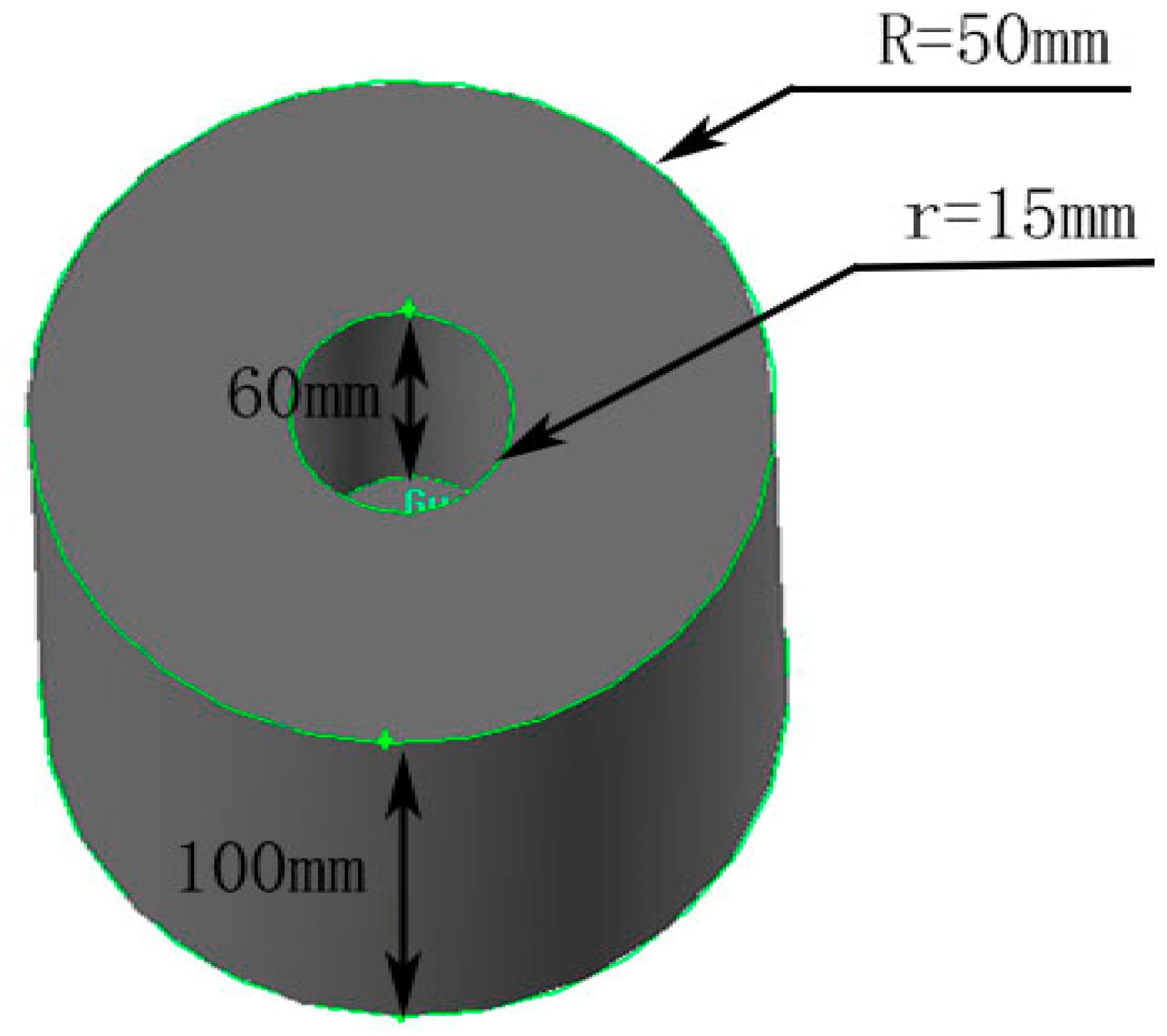
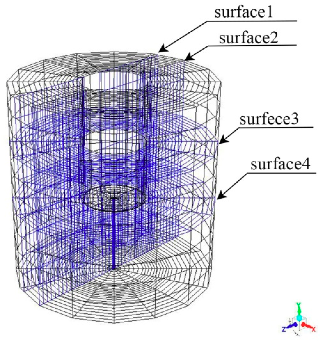
3. Simulation Process

Using Fluent software, the control differential equations were discretized with the finite element method. In this paper, solid modeling is completed with the Gambit software and then imported into software through the Fluent interface to calculate. The three-dimensional model is shown in Figure 1. The origin of the model is the center of the crystal generator. The dimensions of the generator were 60 mm in height and 15 mm in diameter, while the dimensions of the casting mold were 100 mm in height and 50 mm in diameter.
As shown in Figure 2, the three-dimensional model was a meshed hexahedron [19], whereas the z-axis was the vibration direction of the crystal generator. Since the cooling conditions and shape of the casting mold were symmetrical along the y-axis direction, the temperature and flow fields formed symmetrical distribution. Four surfaces were selected as the research and analysis objects.

4. Results and Discussion

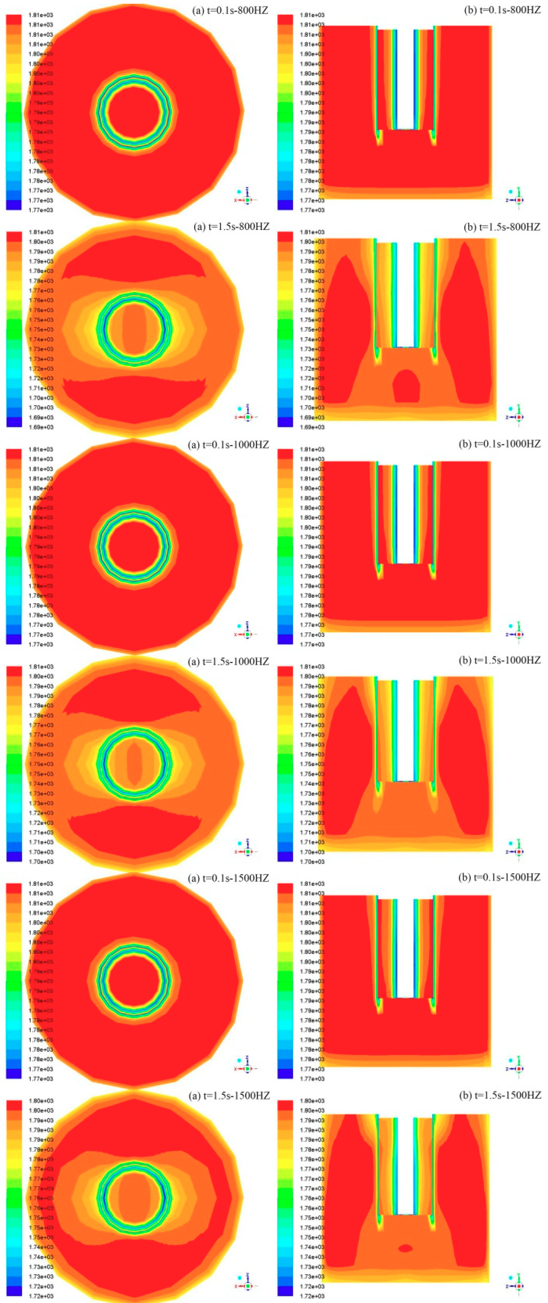
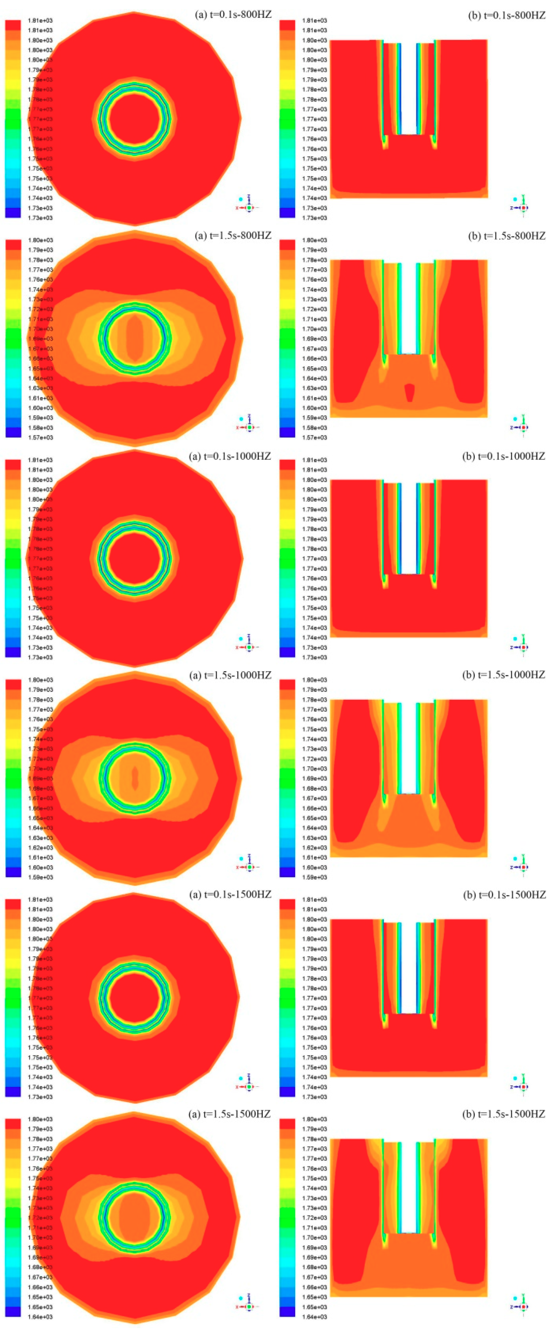
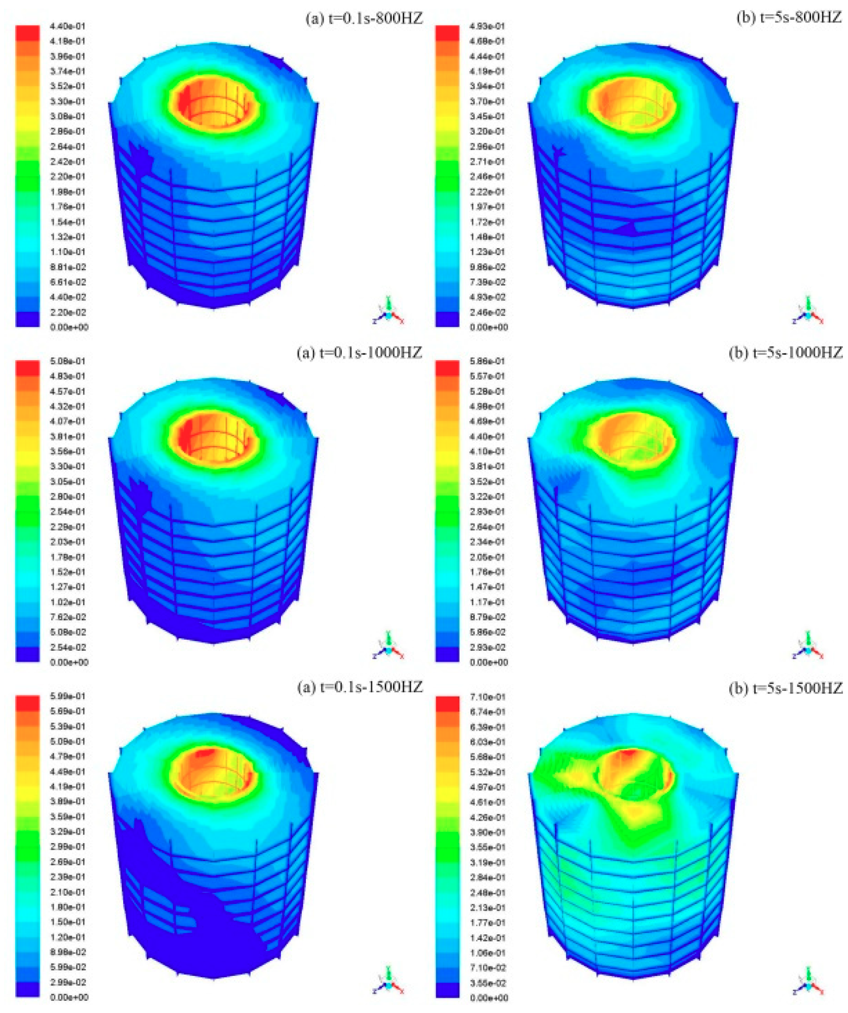
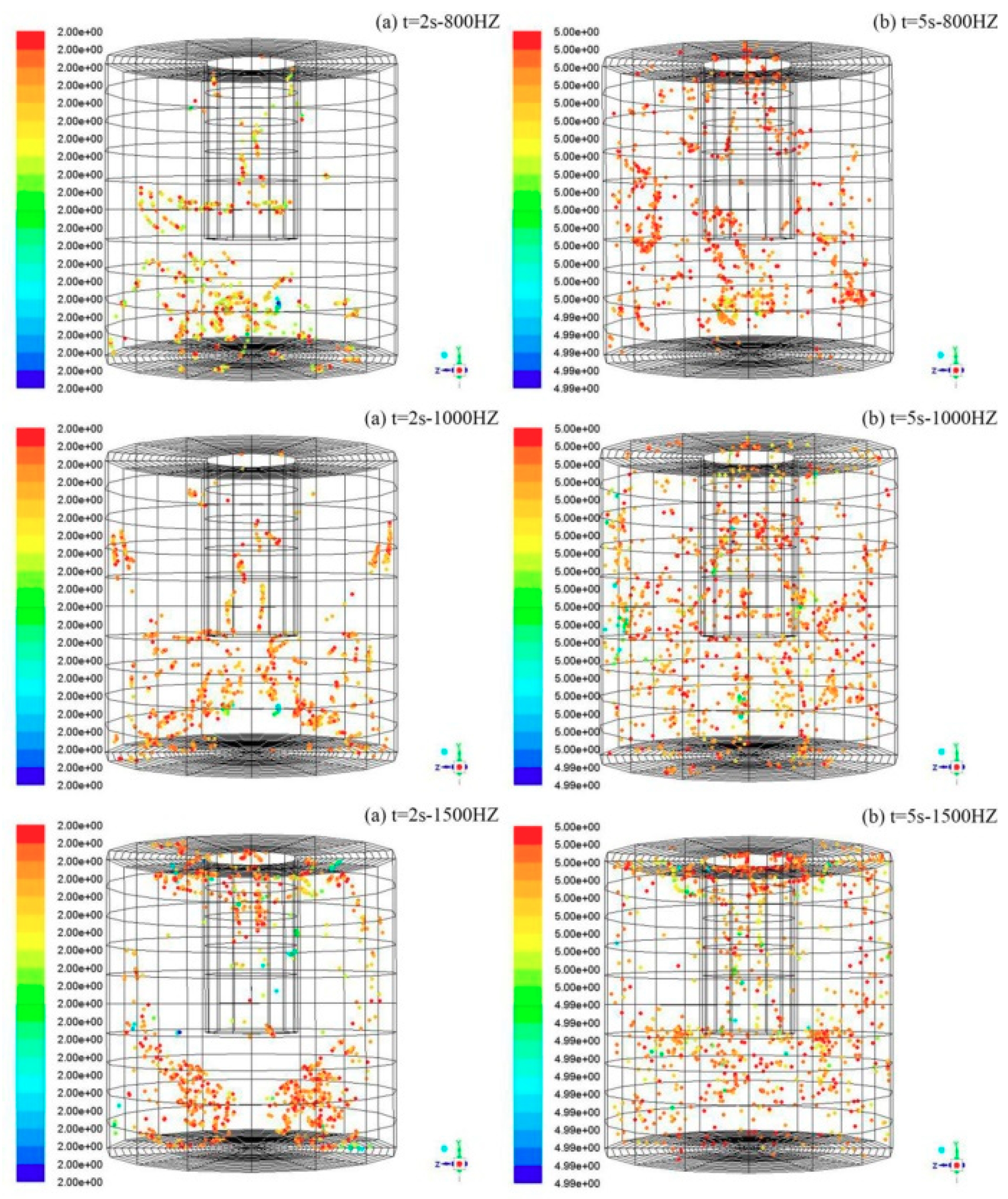
4.1. Temperature Field Distribution

The driving force of the liquid metal was the degree of undercooling on the cooling surface of the crystal generator. Different representative degrees of undercooling were selected in this paper. After the simulation of Fluent software, the distribution of the temperature field was expressed by a post-processing module. According to the established model, the temperature field distribution in ferrite stainless steel Cr17 with different degrees of undercooling and vibration frequencies was simulated. The temperature field distributions of four surfaces with different degrees of undercooling and vibration frequencies (the amplitude is 0.20 mm) at 0.10 s and 1.50 s are shown in Figure 3 and Figure 4.
It can be seen from Figure 3 and Figure 4 that the temperature field presented symmetrical distribution along the vibration direction of the nucleus generator and the effect of frequency on the temperature field was less than the degree of undercooling, which was almost negligible. Among the three frequencies, the temperature diffused fastest under the condition of 1000 Hz. The effect of the degree of undercooling on the temperature field is discussed below at a constant frequency of 1000 Hz. Through the heat transfer analysis of the ferritic stainless steel casting and the crystal nucleus generator, the temperature field was outwardly diffused by a positive temperature gradient. The direction of movement of the solid–liquid interface during solidification was opposite the direction of heat transfer. The degree of undercooling was 540 K, the temperature near to the crystal nucleus generator was 1700 K, and the temperature at the edge was 1810 K at the time of 1.5 s. The core and edge temperature difference of the crystal nucleus generator was 110 K when the degree of undercooling was 1040 K. The temperature near the crystal nucleus generator was 1590 K and the temperature at the edge was 1800 K at the time of 1.5 s, and the core and edge temperature difference of the crystal nucleus generator was 210 K. At this time, the melt partial region was in the solid–liquid two-phase region, and a small temperature gradient was favorable for simultaneous nucleation in the melt. Thus, it is beneficial to the growth of equiaxed crystals when the degree of undercooling is 540 K. At the initial stage of solidification, the isotherm perpendicular to the vibration direction was circular and then gradually became elliptical as the solidification progressed. This is because the cooling strength of the surface of the crystal nucleus generator and the inside of the melt was different. The overall change law of the temperature field was studied at a frequency of 1000 Hz and a 540 K degree of undercooling. The temperature perpendicular to the vibration direction was lower than the vibration direction, and the liquid phase in the vibration direction was in an overheated state and could not be nucleated. As the solidification progressed, the overheated zone gradually decreased, which was beneficial to the growth of equiaxed crystals.
In order to rapidly form a large number of grains on the surface of the crystal nucleus generator inserted into the liquid metal, and to ensure that the grains can be continuously ejected into the liquid metal, the degree of undercooling between the surface of the crystal nucleus generator and the liquid metal must be appropriate. Otherwise, when the surface of the crystal nucleus generator is completely covered by the growing nucleus, then a complete solidified shell is formed, and the nucleation rate of the non-spontaneous nucleation on the surface of the crystal nucleus generator is zero. A schematic diagram of the different frequency solidification processes under a degree undercooling of 540 K is shown in Figure 5.
The label value on the left side of Figure 5 is the liquid fraction, indicating the degree of solidification. It can be seen from Figure 5 that the solidified shell is first generated in the direction of vibration, then is generated perpendicular to the direction of vibration, and finally diffuses to the surroundings to form a closed shell. As the frequency increases, the liquid fraction around the crystal nucleus generator gradually increases, which effectively inhibits the formation of solidified shells. Figure 6 shows the solidification process when the degree of undercooling is 1040 K and the frequency is 1500 Hz. It can be clearly seen in Figure 5 and Figure 6 that the main factor affecting the formation of the solidified shell is the degree of undercooling rather than the frequency. A low degree of undercooling can prevent solidified shells from forming rapidly on the surface of the nucleus generator, thereby promoting the release of the grains.

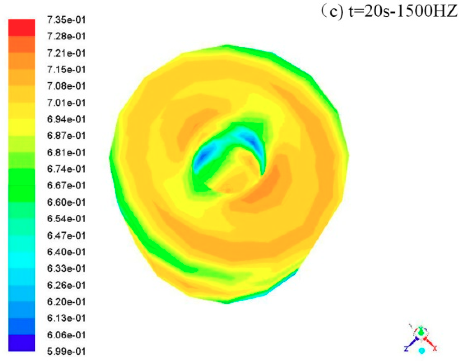
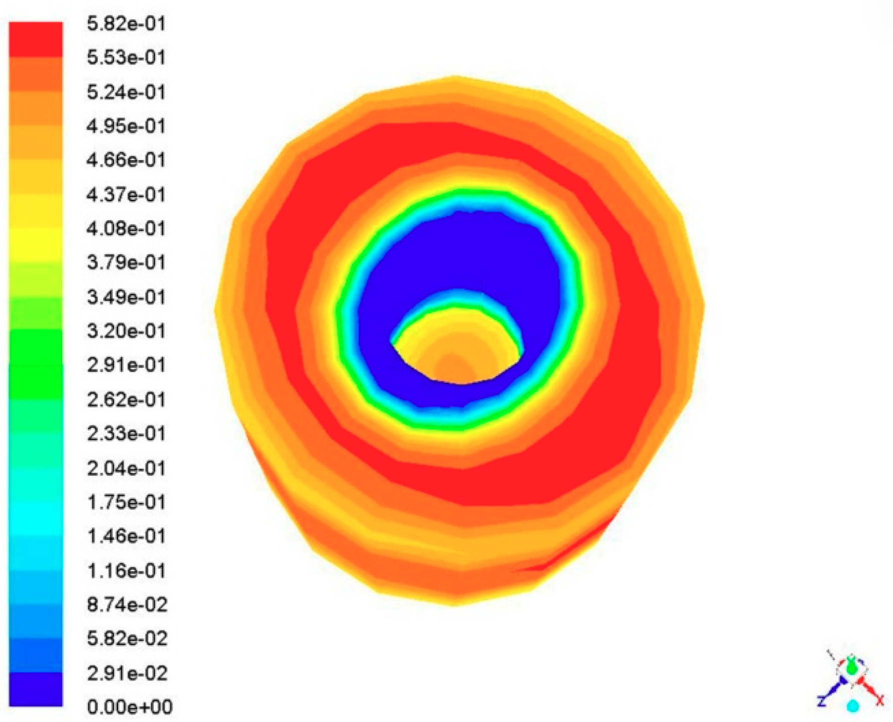
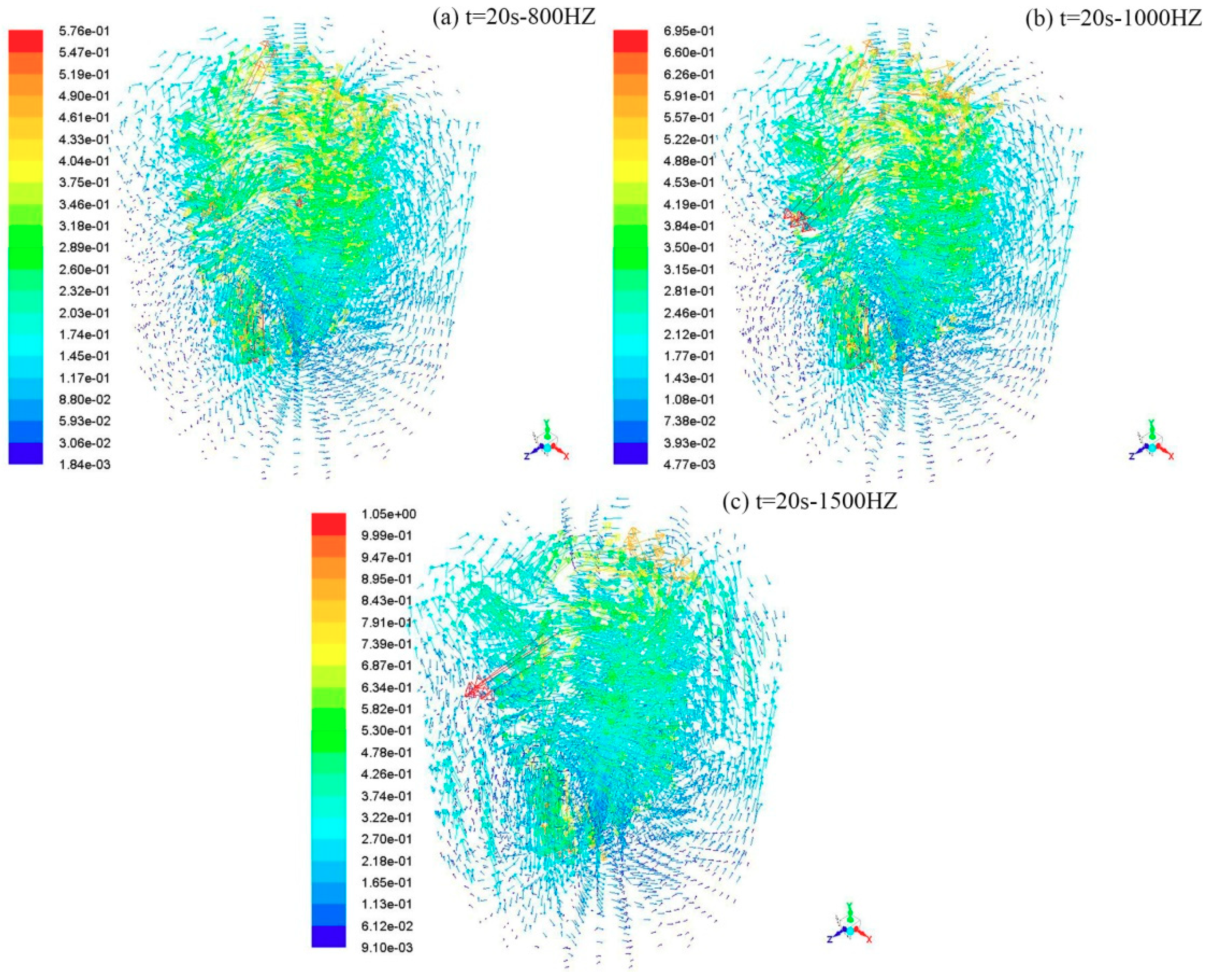
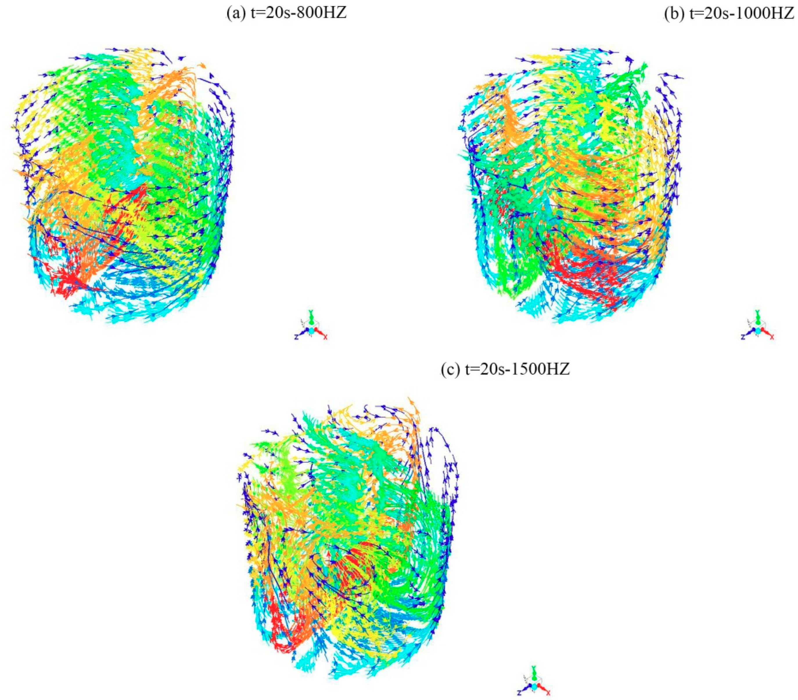
4.2. Flow Field Distribution

Fluid flow leads to the transportation of heat and matter, which ultimately has an important impact on the microstructure and properties of materials. The flow of liquid metal is greatly enhanced by mechanical vibration, which reduces the temperature gradient and helps to eliminate overheating. The stripping of the grains under vibration conditions largely depends on the magnitude of the vibration frequency. In this paper, the vibration frequency is used as the simulation control parameter to study the microscopic mechanism of the solidification process. The best degree of undercooling is 540 K, as determined by analyzing the above temperature field. The following analysis of the flow field was carried out under a constant degree of undercooling at 540 K to obtain fluid motion characteristics. Figure 7a–c are vector graphs depicting the velocity regarding ferrite stainless steel liquid metal during solidification at different frequencies. It can be seen from Figure 7 that there was a small recirculation region around the crystal nuclear generator; with the increase of frequency, the rotation velocity in the section increased correspondingly. The trend of the fluid field was studied at a frequency of 800 Hz; the fluid velocity near the crystal nuclear generator was 0.576 m/s and the edge velocity was 0.00184 m/s. It was concluded that compared with other parts of the melt, the tangential velocity gradually decreased from the center to the edge. The existence of rotating tangential velocity of liquid metal can effectively promote the formation of dendrite during solidification, which is beneficial to the growth of equiaxed crystal and the formation of a uniform solidified billet shell.
The flow field distributions with different frequencies (the amplitude is 0.20 mm) at 0.10 s and 5 s are shown in Figure 8. As shown in Figure 8, the flow field exhibited a heart-shaped distribution and spread gradually outward. At the beginning of solidification, the larger velocity was concentrated around the nucleus generator. With the increase of frequency, the velocity increased and the diffusion was faster. At the same frequency, the average velocity and the maximum velocity perpendicular to the vibration direction were both larger than the vibration direction, which shows that the melt fluidity perpendicular to the vibration direction was superior to the vibration direction. Intensive convection can cause the dendrite to break, thereby promoting the formation of equiaxed grains. Therefore, the slow field perpendicular to the vibration direction was more conducive to the formation of equiaxed crystals.
The grains distribution at different frequencies is shown in Figure 9. The scale on the left indicates the length of the grains’ suspension time. The flow characteristics of the melt affect the trajectory of the grains. The grains’ trajectories of different frequencies are shown in Figure 10, and the path is colored by the particle ID in the software. Since the selected degree of undercooling satisfies the critical nucleation undercooling required for nucleation, the grains can be produced. It can be seen from Figure 9 that the grain distribution trend is the same at three frequencies, first concentrated in the vicinity of the nuclear generator, and then mainly concentrated at the lower end of the melt due to the serious natural convection phenomenon caused by gravity. Due to the forced convection caused by the vibration, the grains then moved to the surface of the melt as the fluid moved, and finally reached a uniform distribution. When the lower frequency was 800 Hz, the impact force of the crystal nucleus generator was insufficient to uniformly distribute the crystal grains, causing them to appear in an agglomerated form in some regions, and the time to achieve uniform distribution increased. When the higher frequency was 1500 Hz, it can be seen from Figure 10 that the increasing frequency resulted in a more complex fluid trajectory, and the convection was more severe. Combining this with the flow field analysis results, the velocity around the nucleus generator was too large, and liquid vortexes were easily formed under excessive fluid motion, which easily allowed in gases and impurities so the time for the grains to reach uniform distribution increased. To draw a conclusion from the discussion, the uniform distribution of grains can be achieved at three different frequencies of vibration, but the time required for uniform distribution decreases first and then increases with the increase of frequency.

5. Conclusions

The simulation results show that the effect of the degree of undercooling on temperature field distribution is greater than that of vibration frequency, and a low degree of undercooling can prevent solidified shells from forming rapidly on the surface of the nucleus generator. The temperature perpendicular to the direction of vibration is lower than that in the direction of vibration. The effect of vibration frequency on the flow field is obvious; the tangential velocity near the nucleus generator is higher than that in other regions, and it increases with the increase of the vibration frequency. The uniform distribution of grains can be achieved at three different frequencies of vibration, but the time required for uniform distribution decreases first and then increases with the increase of frequency. The distribution speed of grains is the fastest when the frequency is 1000 Hz.
Under the conditions of the degree of undercooling at 540 K and a vibration frequency of 1000 Hz, the optimum area for equiaxed crystal formation is the region perpendicular to the vibration direction of the nucleus generator, which not only has enough crystal grains but also satisfies the degree of undercooling condition for growth.

Author Contributions

Conceptualization, W.W. and M.L.; Software, J.C.; Formal analysis, A.W.; Investigation, M.S.; Writing—Original Draft Preparation, W.W.; Writing—Review and Editing, W.W. and M.S.

Funding

This research was funded by the National Natural Science Foundation of China (51074212) and the fund of the State Key Laboratory of Solidification Processing in NWPU (SKLSP201621).

Acknowledgments

The work was supported by the National Natural Science Foundation of China (51074212) and the fund of the State Key Laboratory of Solidification Processing in NWPU (SKLSP201621).

Conflicts of Interest

The authors declare no conflict of interest.

Appendix

There is no simple harmonic vibration setting interface in Fluent software, so the vibration equation of the crystal nucleus generator needs to be imported by writing code, taking the frequency of 800 Hz as an example to give the code as follows:
#include "udf.h"
#include "math.h"
#define PI 3.14159
real vy = 0.0;
static real df = 0.0001;
static real dp = 800;
DEFINE_CG_MOTION(Y_001mm_800Hz, dt, vel, omega, time, dtime)
{
real s;
s = RP_Get_Real("flow-time");
vy = df*dp*2*PI*cos(dp*2*PI*s);
vel[2] = vz;
}
The physical units involved in this code are international standard units, that is, the length unit is m, the speed unit is m/s, and the temperature unit is K.

References

  1. Gan, Y.; Zhao, P.; Wang, M.; Zhao, H.Z.; Tao, H.B.; Yan, C. Physical analogue of liquid metal original position nucleation stirred by vibration. J. Iron Steel Res. 2006, 18, 9–13. (In Chinese) [Google Scholar]
  2. Zhang, H.; Tao, H.; Li, F.; Wang, M.; Huang, W.; Zhao, P. Research on mechanism of nucleation in liquid metal excited by vibration. Steel 2008, 43, 20–24. (In Chinese) [Google Scholar]
  3. Johnson, D.R.; Inui, H.; Muto, S.; Omiya, Y.; Yamanaka, T. Microstructural development during directional solidification of α-seeded TiAl alloys. Acta Mater. 2006, 54, 1077–1085. [Google Scholar] [CrossRef]
  4. Charbon, C.; Jacot, A.; Rappaz, M. 3D stochastic modelling of equiaxed solidification in the presence of grain movement. Acta Metal. Mater. 1994, 42, 3953–3966. [Google Scholar] [CrossRef]
  5. Dong, H.; Lee, P. Simulation of the columnar-to-equiaxed transition in directionally solidified Al-Cu alloys. Solid State Phenom. 2005, 139, 129–134. [Google Scholar] [CrossRef]
  6. Liao, D.; Cao, L.; Sun, F.; Chen, T. Research status and prospect on numerical simulation technology of casting macroscopic process. Acta Metall. 2017, 54, 161–173. (In Chinese) [Google Scholar]
  7. Kuo, J.K.; Huang, P.H.; Guo, M.J. Removal of CrMo alloy steel components from investment casting gating system using vibration-excited fatigue failure. Int. J. Adv. Manuf. Technol. 2016, 89, 1–11. [Google Scholar] [CrossRef]
  8. Lyubimov, D.V.; Lyubimova, T.P.; Parshakova, Y.N.; Roux, B.; Lan, C.-W.; Yu, W.-C. Effect of high-frequency vibrations on oriented crystallization of binary alloys. J. Surface Investig. X-ray Synchrotron Neutron Tech. 2009, 3, 116–120. [Google Scholar] [CrossRef]
  9. Lyubimova, T.P.; Parshakova, Y.N. Numerical investigation of heat and mass transfer during vertical Bridgman crystal growth under rotational vibrations. J. Cryst. Growth 2014, 385, 82–87. [Google Scholar] [CrossRef]
  10. Su, Y.J.; Liu, X.H.; Wu, Y.F.; Huang, H.-Y.; Xie, J.-X. Numerical simulation of temperature field in horizontal core-filling continuous casting for copper cladding aluminum rods. Inter. J. Miner. Metal. Mater. 2013, 20, 684–692. [Google Scholar] [CrossRef]
  11. Ko, E.Y.; Yi, K.W.; Park, J.K.; Cho, J.W.; Shin, H.-J. Numerical modeling and analysis of the thermal behavior of copper molds in continuous casting. Met. Mater. Int. 2010, 16, 281–288. [Google Scholar] [CrossRef]
  12. Xia, Y.J.; Wang, F.M.; Wang, J.L.; Li, G.-Z. Simulation of the continuous casting process in a mold of free-cutting steel 38MnVS based on a MiLE method. Int. J. Miner. Metal. Mater. 2011, 18, 562–569. [Google Scholar] [CrossRef]
  13. Gandin, C.A.; Rappaz, M. A coupled finite element-cellular automaton model for the prediction of dendritic grain structures in solidification processes. Acta Metal. Mater. 1994, 42, 2233–2246. [Google Scholar] [CrossRef]
  14. Wang, J.L.; Wang, F.M.; Li, C.R.; Zhang, J.-M. Effects of carbon and phosphor contents on microstructure of a free-cutting steel 9SMn28. Trans. Mater. Heat Treat. 2010, 31, 60–64. [Google Scholar]
  15. Wang, J.; Wang, F.; Li, C.; Zhang, J. Simulation of solidification microstructure and columnar to equiaxed transition in free-cutting steel 9SMn28 based on a CAFE method. Steel Res. Int. 2010, 81, 150–157. [Google Scholar] [CrossRef]
  16. Pedlosky, J.; Leibovich, S. Geophysical Fluid Dynamics; Springer: New York, NY, USA, 1987. [Google Scholar]
  17. Yang, X.; Li, M.; Ma, W.H.; Lv, G.Q.; Luo, T.; Wang, Y.F. Numerical simulation on the heat transfer performance of multicrystalline silicon in directional solidification process. Appl. Mech. Mater. 2013, 444–445, 1412–1416. [Google Scholar] [CrossRef]
  18. Mills, K.C.; Su, Y.; Li, Z.; Brooks, R.F. Equations for the calculation of the thermophysical properties of stainless steel. ISIJ Intern. 2007, 44, 1661–1668. [Google Scholar] [CrossRef]
  19. Liu, L.; Nakano, S.; Kakimoto, K. Dynamic simulation of temperature and iron distributions in a casting process for crystalline silicon solar cells with a global model. J. Cryst. Growth 2006, 292, 515–518. [Google Scholar] [CrossRef]
Figure 1. Three-dimensional model used in this study.
Crystals 09 00174 g001
Figure 2. Finite element mesh generation of 3D model.
Crystals 09 00174 g002
Figure 3. Temperature field of ferritic stainless steel Cr17 with a degree of undercooling of 540 K.
Crystals 09 00174 g003
Figure 4. Temperature field of ferritic stainless steel Cr17 with a degree of undercooling of 1040 K.
Crystals 09 00174 g004
Figure 5. A schematic diagram of the solidification process at different frequencies when the degree of undercooling is 540 K.
Crystals 09 00174 g005aCrystals 09 00174 g005b
Figure 6. A schematic diagram of the solidification process when the degree of undercooling is 1040 K.
Crystals 09 00174 g006
Figure 7. Velocity vector charts of the ferrite stainless steel Cr17 flow field at different frequencies.
Crystals 09 00174 g007
Figure 8. Flow field in ferritic stainless steel Cr17 at different frequencies.
Crystals 09 00174 g008
Figure 9. Grain distribution under different vibration times.
Crystals 09 00174 g009
Figure 10. The trajectory of grains at different frequencies.
Crystals 09 00174 g010
Table 1. The thermodynamic parameters of ferritic stainless steel Cr17 material.
Temperature / K Density /
kg / m 3
Specific Heat/
J K 1 k g 1
Viscosity/
Pa · s
Thermal Conductivity/
W m 1 K 1
29377004600.0022535.100
181368007150.00730734.669

