Stress Heterogeneity Leading to Void Nucleation within Spherulites for Semi-Crystalline Polymers

Mines ParisTech, PSL University, Centre des Matériaux (CMAT), UMR CNRS 7633, BP 87, 91003 Evry Cedex, France
Crystals 2019, 9(6), 298; https://0-doi-org.brum.beds.ac.uk/10.3390/cryst9060298
Submission received: 26 April 2019
/
Revised: 31 May 2019
/
Accepted: 6 June 2019
/
Published: 8 June 2019
(This article belongs to the Special Issue Microstructure Evolutions and Mechanical Behavior of Semicrystalline Polymers)
Abstract
:Linking the microstructure to the mechanical properties is a key feature in the design and assessment of the durability of semi-crystalline polymers. This paper addresses the importance of a particular architecture inside spherulites. The use of the theoretical tools of continuum mechanics has been combined with experimental observations of the deformation of the microstructure. Microstructural heterogeneities at various scales induced critical regions in the spherulite where voiding has been reported. The local stress state has been investigated using a Finite Element code. A simple Hooke’s law was used for meshes accounting for the alternating crystalline and amorphous lamellae. This allowed a better understanding of the loci of void nucleation in the equatorial region, as well as in the “polar fans”, and were explained by using a criterion based on stress equi-triaxiality.
1. Introduction
Many research studies on engineering materials deal with the relationship between the microstructure and material properties. Some of these studies focus on experiments consisting of the examination of the initial microstructure followed by a measurement of the deformation of this microstructure under loading. The mechanical properties are then analysed by using the tools of Continuum Mechanics, sometimes with the assistance of a Finite Element (FE) code.
For semi-crystalline polymers exhibiting spherulitic microstructures, a first category of studies sketches the deformation inside the spherulites by discussing the relative motions between the amorphous/crystalline lamellae. When the spherulite is submitted to a uniaxial tensile stress, the crystalline lamellae are considered to experience planar tension, slippage, and uniaxial tension in the equatorial, diagonal, and polar directions, respectively. Under these considerations a spherulite was supposed to be submitted to a uniaxial tension, irrespective of the influence of the surrounding spherulites. Constitutive models, with various degrees of sophistication, have been proposed so far.
In the present work, two degrees of heterogeneity inside the spherulite were considered:
Recent results reported by Xiong et al. [3,4] showed deformation heterogeneity measured in two specific directions: the one in the axial (called “polar”) direction, and the other in the radial (called “equatorial”) direction. On the other hand, Selles et al. [2] reported voiding—supposed here to be a volumetric deformation—in the same polar and equatorial directions.
The objective of this paper is to obtain a better understanding of the interaction between these heterogeneities in terms of microstructure and deformation, in light of continuum mechanics. The local deformation fields reported previously associated with the location of the equi-triaxial stress state leading to the formation of voids in the polar fans, as well as the equatorial rings, are discussed.
To this end, the essential conclusions of the reports summarizing the heterogenetity in the microstructure and its deformation are first recalled. Then, the theory of the uniaxial deformation leading to an equi-triaxial stress state is developed, followed by the FE conditions of computations. By gradually introducing heterogeneity in the microstructure, the stress/strain fields in the spherulite will be presented in the results. The final section introduces the criteria allowing the localization of the first appearance of voids. The discussion concerning the effects of the surrounding spherulites takes place at the end of the paper.
2. Methods
2.1. Microstructural Heterogeneity
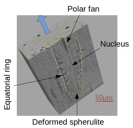
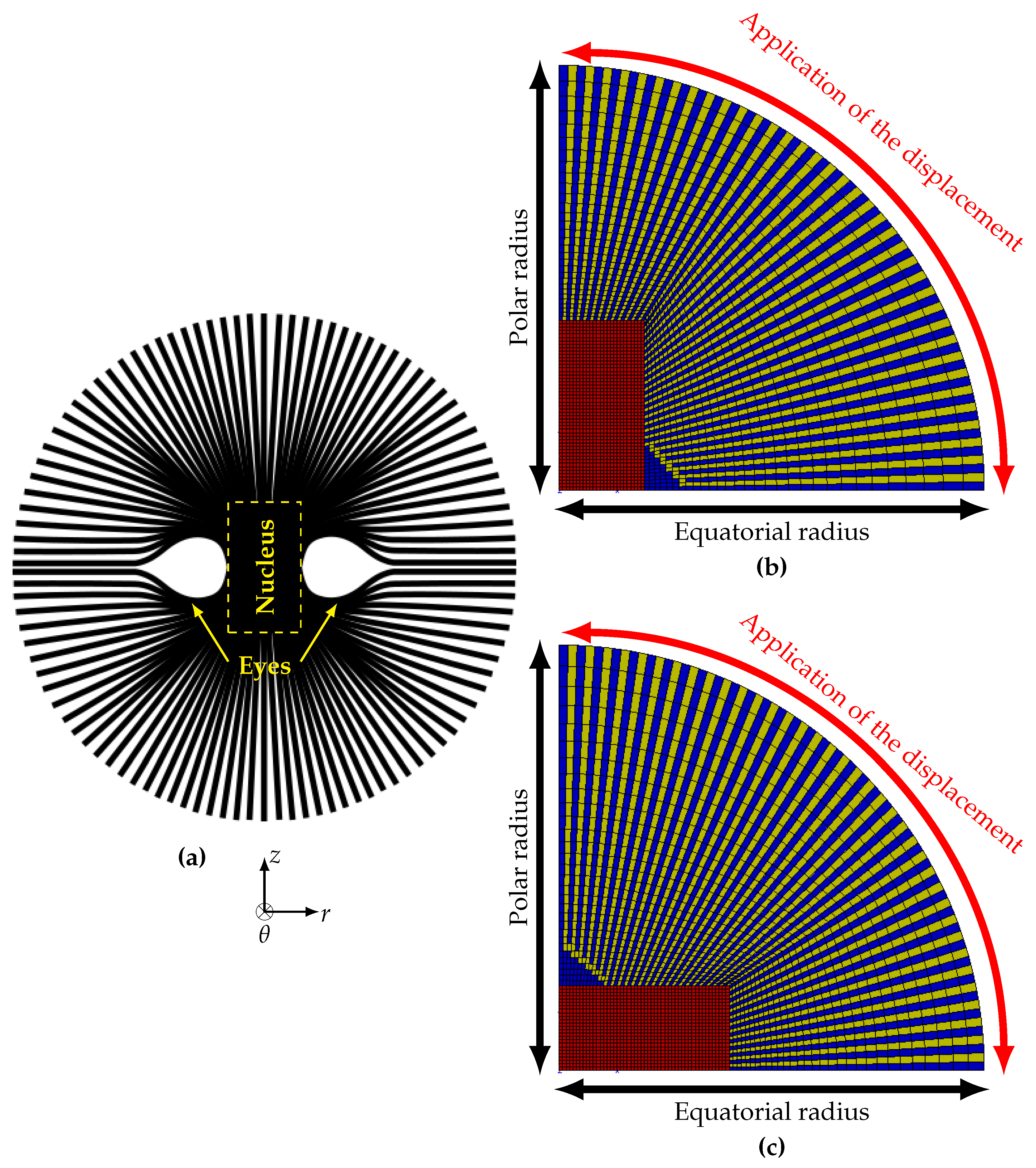
In this section, attention has been paid to spherulites where their development was reported to occur from a single initiation site. The growth mechanisms started from a single lamella to form a hedrite, then to a sheaf, and finally to the complete spherulite [1]. These crystallization mechanisms lead to a particular structure that can deviate from the so far assumed isotropic and homogeneous spherulite. Figure 1a shows a sketch of such a structure where the presence of “eyes” due to the processing has been reported and modelled by Gránásy et al. [5]. The experimental techniques allowing the observations of the spherulitic microstructures were listed by Crist and Shultz in their critical review [1] as follows: optical microscopy with polarized light; scanning electron microscopy (SEM); transmission electron microscopy (TEM); atomic force microscopy (AFM); microbeam X-ray diffraction and scattering; and Infrared and Raman spectroscopy.
The presence of crystallite lamellae with their specific orientation generates heterogeneous deformation inside the spherulite. Xiong et al. [3,4] reported measurements of the average deformation at the scale of few crystalline lamellae for various types of polyethylene (PE) by using SAXS and WAXS techniques. The crystalline lamellae located in the equatorial zone of the spherulite experienced biaxial strains for which the value in the radial direction was less than that of the hoop (circumferential) strain. In the pole direction, the radial strain was greater than the hoop strain. These authors reported for instance that for one of the PE studied, a radial strain of about 1% was quantified.
Recent advances in the synchrotron radiation computed tomography technique allow examinations of microstructures with a voxel side size of 50 nanometres [6,7]. One main advantage of this non-destructive technique is to obtain 3D images of the deformed spherulites without any tedious preparation of thin films before the observation. By using this technique, attention has been paid here to two studies dealing with semi-crystalline polymers exhibiting spherulitic microstructures. Morgeneyer et al. [8] observed nanovoid morphology and distribution in a deformed high density polyethylene. Nanovoids were studied regardless of their location inside the small spherulites. A recent paper by Selles et al. [2] analyzed the distribution of the voids within over one hundred observed spherulites, in their deformed configuration. It was reported that:
- there was a cylindrical region located in the centre of the spherulite where no void was observed. This unvoided region is called the nucleus in Figure 1a;
- the equatorial plane showed a cluster of voids forming more or less regular rings or parts of rings;
- perpendicular to the equatorial plane, voids were arranged as polar fans [9], i.e., in columns separated by walls of dense matter. The formation of these polar fans is intriguing but few studies have examined this process. This is one of the goals of the present paper;
- in the same deformed sample, the distribution of voids within the spherulites could be as equatorial rings or as polar fans, as both of these two configurations in the same spherulite;
- in the necked region, voids developed shapes that were in line with the observations of Xiong et al. [3,4]. Voids were disc shaped with an elliptical form in the equatorial zone, the larger axis being in the circumferential direction (hoop strain). In the polar direction they were cylindrical, with a height in the radial direction greater than the section radius (hoop direction).
In the following, the void volume fraction was considered as volumetric deformation [2]. The cylindrical coordinates will be considered as sketched in Figure 1a. Linking the observed heterogeneity of deformation to the complex stress state at an acceptable scale for continuum mechanics constitutes the main motivation of the present work. To this end, the spherulite radius will be assumed to be the characteristic length. Selles et al. [2] reported that for one of polyamides studied, the nucleus had a radius of and a height of . By extension, each length will be normalized with respect to .
2.2. Theory of Uniaxial Strain
The uniaxial tensile test is most often used to study the mechanical properties of a given material. In this kind of test, the uniaxial character refers to the stress state: the stress tensor is uniaxial whereas the strain tensor is triaxial. Hooke’s law is valid for small strains and makes use of two material parameters, e.g., the Young’s modulus E and the Poisson’s ratio .
In this section, a uniaxial deformation test has been considered, still under small strain conditions formulation. This kind of loading has been studied in rubber materials subjected to constrained compression as in the bearing systems [10]. The so-called oedometric test consists of compressing a disk placed inside an undeformable cylinder, so that . The uniaxial deformation is the unique non null component.
Hooke’s law gives:
where ; is the Krönecker’s symbol, i.e., when and when ; .
The rubbery amorphous phase being quasi-incompressible, the Poisson’s ratio is , therefore, Equations (3) and (4) yield:
For the sake of simplicity, the diagonal components of the stress tensor () will be noted as () respectively.
A modified definition of the stress triaxiality ratio has been introduced so as to characterize the multiaxial stress state:
where is the maximum principal stress. This latter is used instead of the equivalent stress since no plasticity is accounted for here. It should be noted that takes the value of unity for equi-triaxial stress (Equation (5)). However, the reciprocity is not obeyed i.e., does not necessarily reflect an equi-triaxial stress state; for instance when there is a difference between the maximum and the minimum principal stresses. This difference has then been characterized by the parameter defined as:
For the equi-triaxial stress state should be equal to zero, assuming that is the maximum principal stress and .
According to Dorfmann et al. [10], the equi-triaxial stress state can be achieved under tensile loading if the disc presents a shape factor (ratio between the height and the radius) of less than 1/7. Moreover, positive transverse deformations enhance this triaxial stress state.
In the following, the amorphous phase inside the spherulite is supposed to be in a rubbery state. Equation (5) is assumed to apply. When a quasi-incompressible rubber is subjected to an equi-triaxial stress state, void nucleation and growth are considered to occur for a critical mean stress [11,12,13,14].
It is to be noted that the configuration of the spherulite in Figure 1a may result in two critical cases of uniaxial deformation of the rubbery amorphous phase:
- in the equatorial region because of the very low shape factor;
- in the polar radius where the rigid crystalline phase surrounding the amorphous phase is supposed to have no transverse deformation.
2.3. Finite Element Method
In the framework of continuum mechanics, an in-house, Finite Element (FE) code [15,16] was used to analyze the multiaxial stress state in a complex architecture inside the spherulite.
Figure 1b illustrates half of a spherulite presented with an assumed axial symmetry. Quadratic axisymmetric elements with reduced integration were considered. The mesh contained 3500 elements and 21,422 degrees of freedom. The minimum mesh size in the nucleus was about 8 × 10. The “eye” of the spherulite can be observed in the equatorial region close to the nucleus boundary. From the numerical simulation viewpoint, it is worth noting that the presence of a stiff nucleus in the centre of the spherulite permitted the difficulty concerning the singular point dealing with the centre of the spherulite to be overcome.
The illustration shown in Figure 1b using cylindrical coordinates reveals that the boundary conditions applied to the mesh were as follows:
- The vertical arrow called the “polar path” representing the revolution axis was blocked in both r and directions;
- The horizontal arrow called the “equatorial path” was blocked in the z direction by symmetry with respect to the equatorial plane;
- z and r displacements were applied respectively to the curved node set indicated by the red arrow in Figure 1b. Two case studies were considered:
- -
- positive z-displacement, letting r-displacement be free for the uniaxial stress tensor applied to the spherulite;
- -
- positive z-displacement and zero r-displacement for the uniaxial strain tensor, representing a constrained spherulite located in the central part of the specimen;
A specific case of z-displacement perpendicular to a plane passing through the eyes has also been considered. This was performed by rotating the mesh so that the nucleus lay in the equatorial zone, transverse to the z direction (Figure 1c).
The z-displacement was calculated so as to obtain a local maximum principal strain of about 1% within the spherulite. This value was reported by Xiong et al. [3,4] for various types of polyethylene.
Three continuum media have been considered, each showing linear elastic behaviour and consisting of an amorphous phase; a crystalline phase and a homogenized semi-crystalline polymer. The amorphous phase was assumed to be in a rubbery state with a Young’s modulus of 3 MPa (Shear modulus = 1 MPa) and a Poisson’s ratio of 0.49. This latter value allowed for efficient computation with acceptable results. For the crystalline phase, a Young’s modulus of 10 MPa was selected based on results given in the literature [3,4]. The Young’s modulus of the homogeneous semi-crystalline polymer of 501.5 MPa was obtained by using the rule of mixtures. The coefficient of Poisson of the crystalline phase and the homogenized semi-crystalline polymer was assumed to be 0.4. It should be noted that the eyes of the spherulite were considered to be made up of the rubbery amorphous phase.
As mentioned in Section 2.2, the critical stress [11,12,13,14] takes a value of 2.5 MPa for the amorphous phase. In the following, any stress value will then be normalized by .
3. Results
The present results essentially deal with FE numerical simulations. The strain and stress distributions were plotted with respect to the axial and radial paths. These abscissae were normalized by the spherulite radius: and respectively. The stress was normalized with respect to .
The first results concern a spherulite subjected to a uniaxial stress tensile state. The cylindrical coordinates were recalled in each mesh. The parameters (abscissa and ordinate) of each graphics were normalized—except for the strain distribution—so as to obtain the same scale. The effects of various microstructures have first been analyzed.
3.1. Homogenized Spherulite
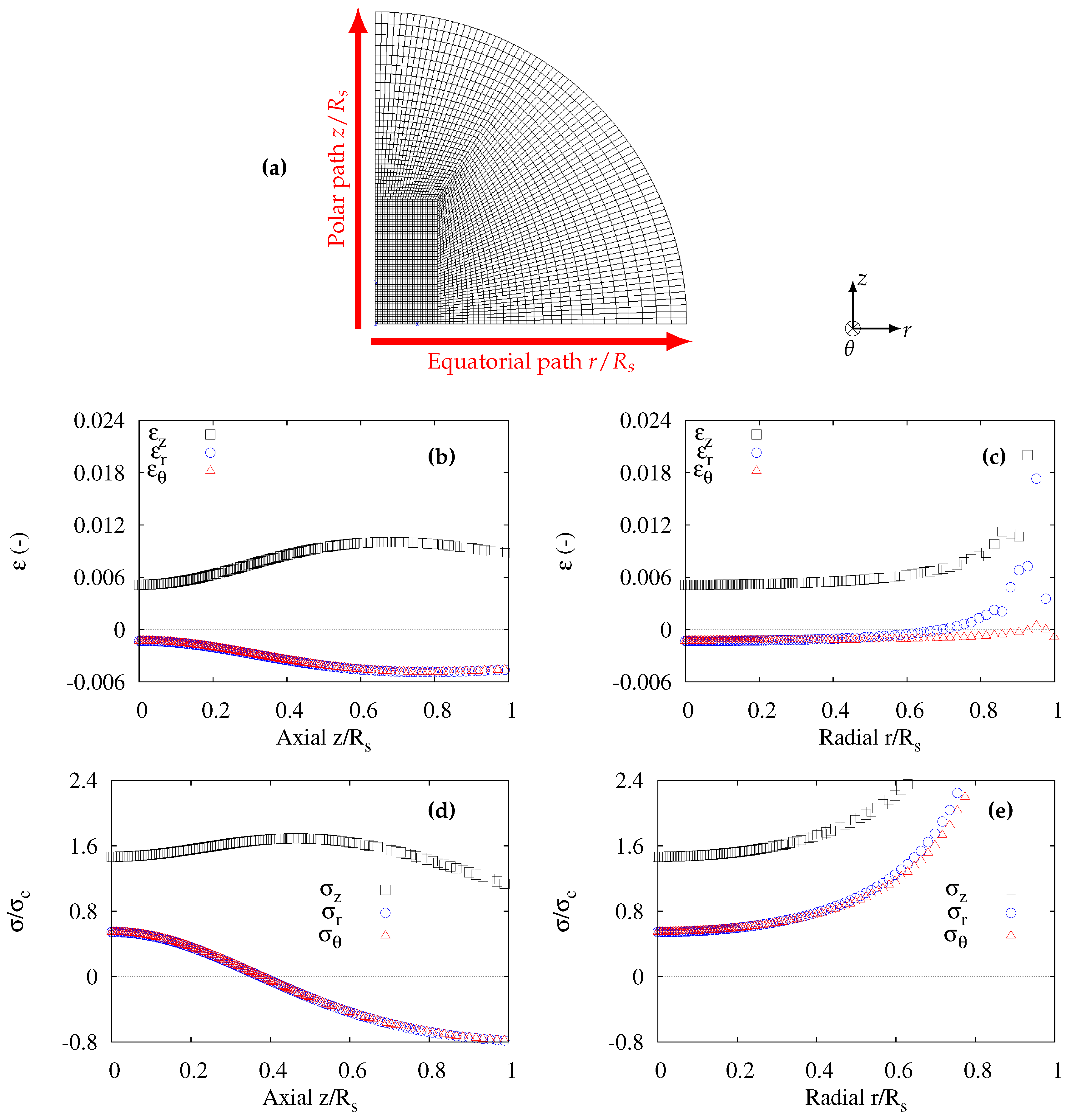
Figure 2a illustrates the mesh used by considering the spherulite as a homogenized medium. The axial and radial paths, respectively characterized by and , are indicated. The strains as functions of and have been plotted in Figure 2b,c respectively. In all cases, was always the maximum principal strain. It can be observed in Figure 2b that the strains were not homogeneous. The maximum of was located at from the centre of the spherulite. Along the axial path, so that the deformation was considered not to be uniaxial.
Figure 2c shows the three principal strains with respect to the radial path . The variations near the surface () are not to be considered since these are due to “side effects” in the FE computation. Actually, the spherulite being considered alone, the end node of the radial path was located at the free surface and a numerical singularity appears here. Therefore the components of strain were considered supposed to be homogeneous through the radial path. Similar to the axial path, so that the deformation was considered not to be uniaxial.
Concerning the stress distributions, Figure 2d shows the principal stresses along the axial path. As expected from the distributions of the strains, variations of the stresses along the axial path were observed. was always greater than . Moreover, , meaning the maximum principal stress was higher than the critical stress . It should be noted that and stresses were positive for and dropped to negative values for . It can be concluded that:
- for , the stress state was triaxial with all stresses positive, this would facilitate void nucleation although ;
- for , the transverse stresses were negative with rather a high level in absolute value. When subjected to this kind of stress state, the polar crystalline lamellae can be expected to fragment due to macromolecular chains unfolding.
Figure 2e shows the principal stresses along the radial path. The increase of the stresses close to the surface was due to the previously mentioned numerical artefacts (see comments on Figure 2c). It is assumed here that the stresses were homogeneous through the radial path. It is worth noting that all the stresses were positive. The triaxial stress state was encountered with .
3.2. Effect of a Stiff Nucleus Inside a Homogenized Spherulite
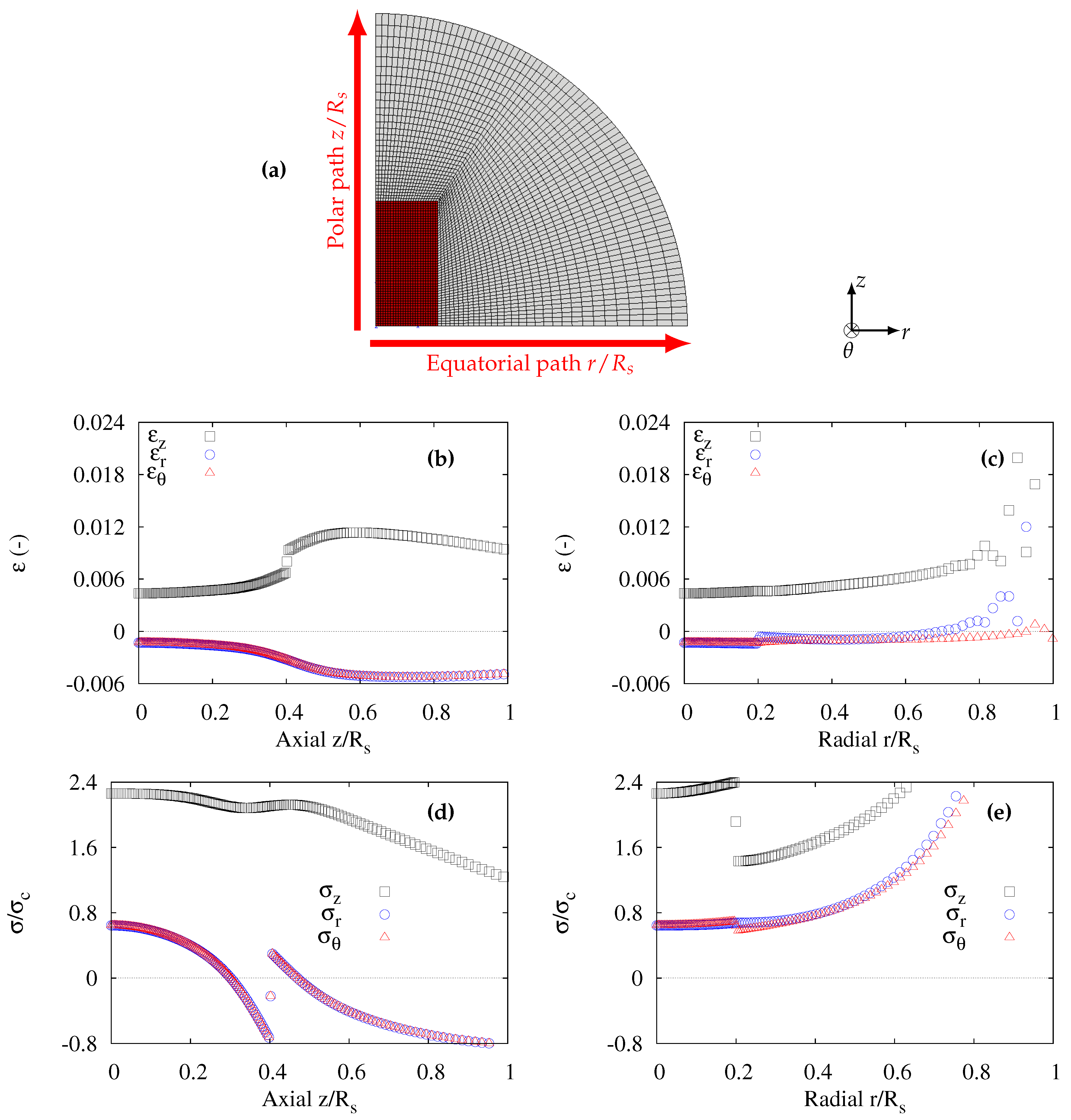
The first heterogeneity of the microstructure dealt with was the presence of the cylindrical nucleus in the centre of the spherulite (Figure 3a). It is recalled that the height and the radius of the nucleus were respectively and . [2]. In addition, the nucleus was stiffer (E = 1000 MPa) than the rest of the spherolite (E = 501.5 MPa).
In Figure 3b, a discontinuity can be observed for at the top face of the nucleus. For the same trend as for homogeneous spherulite was observed, apart from a maximum value of which this time was equal 1.2%, i.e., 20% higher.
Along the radial path, the strains were discontinuous as expected at , corresponding to the boundary of the nucleus (Figure 3c). Again, the strain states were similar to that of the homogeneous state outside the nucleus.
For the distributions of the stresses along the axial path (Figure 3d), it can be observed that the presence of a nucleus modified the situation as follows:
- increase of the component;
- positive for (void nucleation process). These stress components were negative for (fragmentation of crystalline lamellae).
3.3. Spherulite with a Stiff Nucleus and Amorphous/Crystalline Phases
By modelling the crystalline and amorphous phases together with the nucleus (Figure 4a) using the above mentioned materials parameters, the results were drastically modified. Note that the eye was considered as amorphous. As seen in Figure 4b the peak strain moved close to the boundary of the nucleus with a significant increase of the maximum value of . Then, a continuous decrease in was observed along the axial path. .
Figure 4c shows perturbed distributions of strains along the radial path. The peak value of reached 2.4%, whereas was close to zero all along the radial path. In addition, was always negative although negligible with respect to . This situation can be considered as uniaxial deformation.
The distributions of normalized stresses along the axial path are shown in Figure 4d. An equi-triaxial stress state can be observed in the axial path with . It should be noted that the stress values continuously decrease from 0.2 to zero. If the loading were higher so that the maximum value located in the vicinity of the top face of the nucleus reached , void nucleation would be likely to appear in the rubbery amorphous phase. Moreover, it was mentioned previously from homogeneous spherulite results that negative lateral stresses facilitate the fragmentation of the crystalline lamellae around this radial path. The initiation of polar fans [9] was likely to appear due to this multiaxial stress state.
A similar equi-triaxial stress state can be observed in Figure 4e where the distributions of stresses along the radial path were plotted. A slight increase of the stress can be observed in the amorphous eye region. The stress values started from in the eye close to the boundary of the nucleus to near the surface (singular point). For higher loading corresponding to , void nucleation is likely to occur in the amorphous phase. The cluster of these voids would form the equatorial rings.
3.4. Transverse Tensile Stress on a Spherulite
The FE meshes in Figure 4a were modified so as to perform simulations of a transverse tensile test on a spherulite. Indeed, some spherulites may experience this situation inside the specimen tested. Figure 1c and Figure 5a illustrate the change in the orientation of the eye located now in the polar direction. No change has been made either on the paths or on the cylindrical coordinates. Only the position of the boundaries of the nucleus has been modified: 0.4 and 0.2 in the equatorial and polar paths, respectively.
The results are summarized in Figure 5. It can be observed that the same trends occurred as shown in Figure 4 (tension perpendicular to the eyes axis), apart from the coordinates of the oscillations due to the modified boundaries of the nucleus. The equi-triaxial stress state along both radial and axial paths was kept in Figure 5d,e. Therefore, voiding of the amorphous phase could appear on the equatorial region, as well as in the polar fan direction.
4. Discussion
4.1. Equi-Triaxial Stress State on Polar and Equatorial Regions
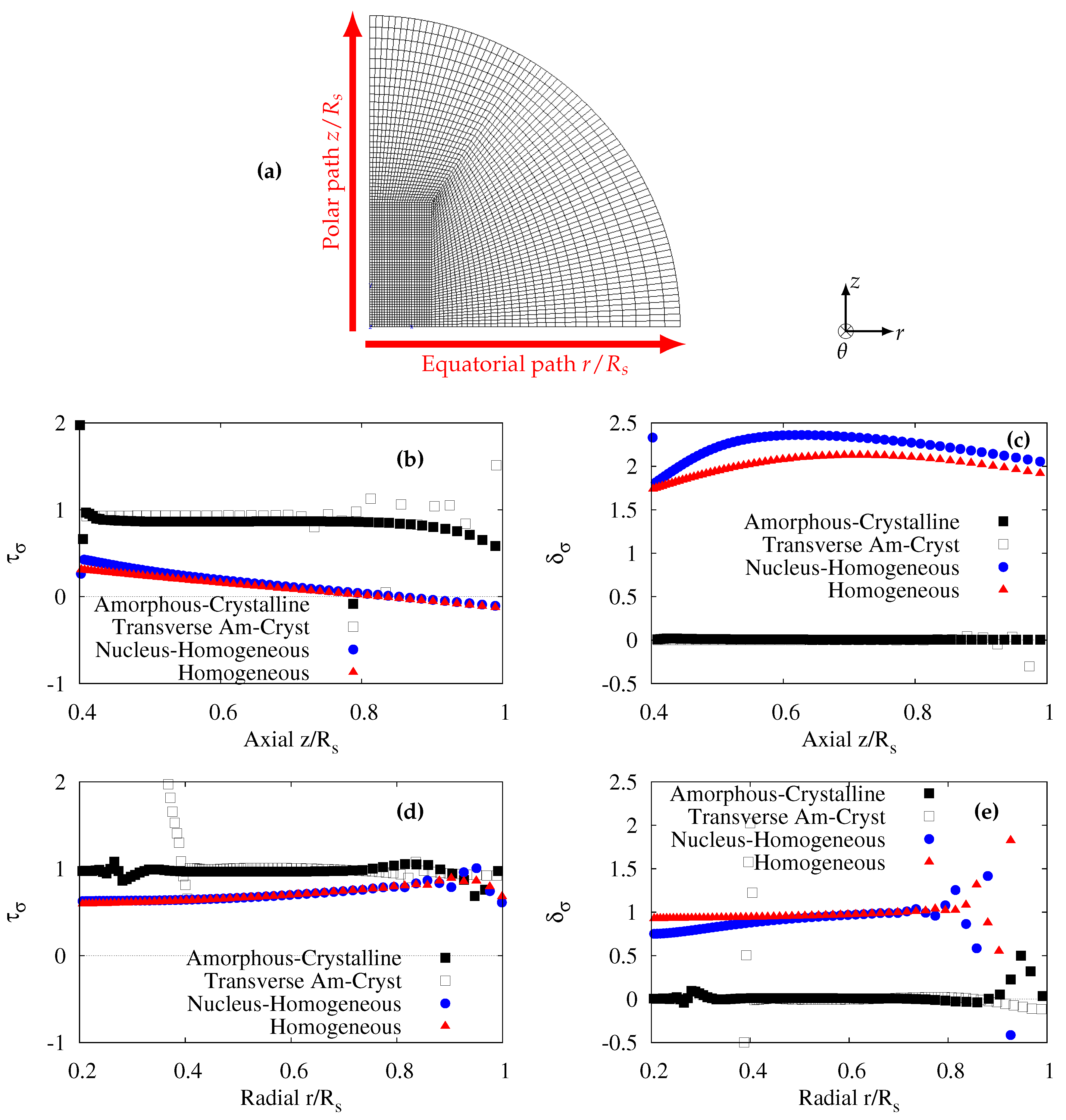
Previous results clearly showed that when the amorphous and crystalline phases were modelled, a triaxial stress state was observed along the equatorial and polar radii and outside the nucleus. This stress state is likely to induce void nucleation in the two directions, allowing the polar fans and equatiorial rings to further develop. To better specify the stress heterogeneity in terms of level (gradient) and multiaxiality, the stress triaxiality ratio (Equation (6)) and parameter (Equation (7)) were used. The keyword “Transverse Am-Cryst” stands for the amorphous plus crystalline model but with a rotated spherulite as in Figure 5. It should be recalled that an equi-triaxial state is characterized by () = (1, 0). Figure 6b–e display the plots of ( and ) for all the studied spherulitic microstructures submitted to uniaxial tensile stress. It can be observed that the homogeneous models (even in the presence of the nucleus) were not able to yield an equi-triaxial stress state. Only models introducing amorphous/crystalline lamellae allowed () to be equal to (1, 0). For the polar direction (Figure 6b), the stress triaxiality ratio slightly decreases starting from a value of 1. This would suggest that the first appearance of voids in a polar fan is close to the nucleus, unless some other geometrical irregularities of the crystalline lamellae exist elsewhere. Figure 6d–e show that the stress triaxiality ratio is constant in the whole equatorial zone, but outside the nucleus. The formation of equatorial rings can then be attributed to this equi-triaxial stress state.
4.2. Effect of Surrounding Spherulites
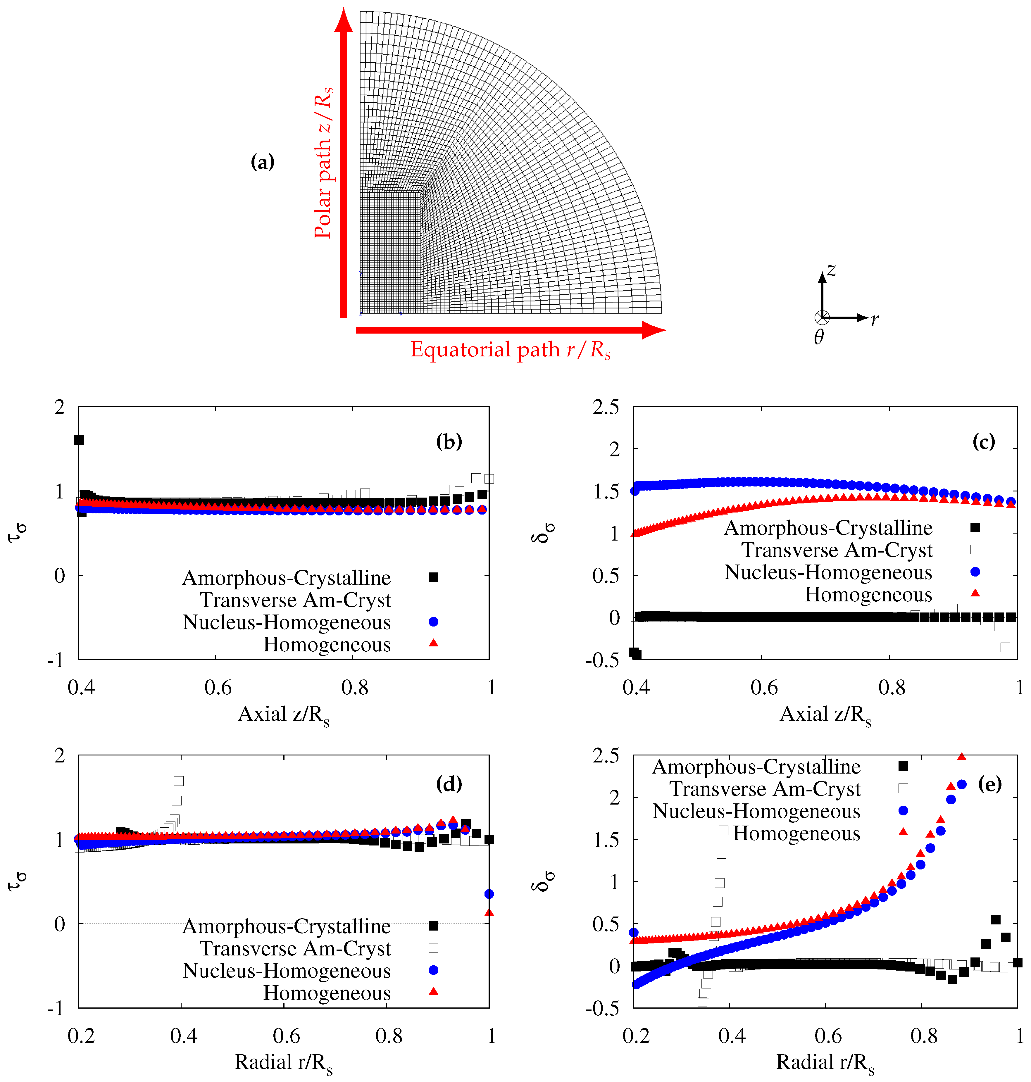
In the previous section, the homogeneous and homogeneous plus nucleus models could not give an equi-triaxial stress state along the axial and radial paths, when the spherulite was subjected to a uniaxial tensile stress. However, if the spherulite were located in the bulk of the specimen (in the central region for instance), the surrounding spherulite could block the lateral deformation as in the tensile oedometric test [10]. An attempt was then made to study if a uniaxial deformation loading applied at the scale of the spherulite boundary would enhance the stress triaxiality ratio for the homogeneous models.
In Figure 7b,d, it can be observed that the four spherulitic microstructures considered previously gave a stress triaxiality ratio of 1. Nonetheless, the homogeneous models with or without the stiff nucleus could not give non null (Figure 7c,e). Homogeneous models cannot predict an equi-triaxial stress state although a uniaxial deformation is applied. In other words, when considering homogeneous spherulites the onset of the void cavitation in the polar and the equatorial regions cannot be predicted.
4.3. Effect of the Loss of Constraint
Actually, the idealized axisymmetric geometry of the spherulite does not reflect the real 3D distribution of crystalline and amorphous of lamellae in space. Indeed, through the circumferential direction the lamellae are not continuous. There is a characteristic length which is the side of the lamellae section. A computation of a thin disc under plane stress conditions was run to analyze the modification of (). As expected, this assumption implied a null hoop stress. This resulted in decreasing without modifying . It is worth noting that the 2D plane stress assumption is also an extreme case since it implies a free surface in the circumferential direction. A complete 3D meshing would be recommended to better understand this effect.
4.4. Effect of Quasi-Incompressibility
In this work, Hooke’s law was used with given elastic parameters for the amorphous phase. In particular, it was assumed that the value of Poisson’s ratio was 0.49. The corresponding bulk modulus determined using Equation (2) is equal to 50 MPa. This value is very low in comparison with current bulk moduli reported for rubbers of about 10 MPa. The alternative would be the use of hyperelastic model with hybrid (quasi-incompressible) elements. It should be noted that the closer Poisson’s ratio is to 1/2, the closer the condition of the stress state is to equi-triaxiality (see Equation (5)). It can be concluded that quasi-incompressible condition for the amorphous phase would enhance void nucleation in the equatorial ring and in the polar fan close to the nucleus.
5. Conclusions
The internal microstructure of a spherulite exhibiting various heterogeneities has been considered by using analytical and FE modelling. The existence of an equi-triaxial stress state could be obtained only when the analysis accounted for the alternating lamellae of crystalline and amorphous phases. In this case, the localisation of this equi-triaxial stress state coincided with the sites of void nucleation leading to equatorial ring and polar fans. It is worth noting that this conclusion dealing with the polar fans formation is one of the most significant results of this study.
Funding
This research received no external funding.
Conflicts of Interest
The authors declare no conflict of interest.
References
- Crist, B.; Shultz, J.M. Polymer spherulites: A critical review. Prog. Polym. Sci. 2016, 56, 1–63. [Google Scholar] [CrossRef]
- Selles, N.; Cloetens, P.; Proudhon, H.; Morgeneyer, T.F.; Klinkova, O.; Saintier, N.; Laiarinandrasana, L. Voiding mechanisms in deformed Polyamide 6 observed at the nanometric scale. Macromolecules 2017, 50, 4372–4383. [Google Scholar] [CrossRef]
- Xiong, B.; Lame, O.; Chenal, J.M.; Men, Y.; Séguéla, R.; Vigier, G. Critical stress and thermal activation of crystal plasticity in polyethylene: Influence of crystal microstructure and chain topology. Polymer 2017, 118, 192–200. [Google Scholar] [CrossRef]
- Xiong, B.; Lame, O.; Séguéla, R.; Men, Y. Micro/macro-stress relationship and local stress distribution in polyethylene spherulites upon uniaxial stretching in the small strain domain. Polymer 2018, 140, 215–224. [Google Scholar] [CrossRef]
- Gránásy, L.; Pusztai, T.; Börzsönyi, T.; Tóth, G.I.; Tegze, G.; Warren, J.A.; Douglas, J.F. Polycrystalline patterns in far-from-equilibrium freezing: A phase field study. Philos. Mag. 2006, 86, 3757–3778. [Google Scholar] [CrossRef]
- Requena, G.; Cloetens, P.; Altendorfer, W.; Poletti, C.; Tolnai, D.; Warchomicka, F.; Degischer, H.P. Sub-micrometer synchrotron tomography of multiphase metals using Kirkpatrick-Baez optics. Scr. Mater. 2009, 61, 760–763. [Google Scholar] [CrossRef]
- Bleuet, P.; Cloetens, P.; Gergaud, P.; Mariolle, D.; Chevalier, N.; Tucoulou, R.; Susini, J. A hard X-ray nanoprobe for scanning and projection nanotomography. Rev. Sci. Instrum. 2009, 80, 056101. [Google Scholar] [CrossRef] [PubMed]
- Morgeneyer, T.F.; Proudhon, H.; Cloetens, P.; Ludwig, W.; Roirand, Q.; Laiarinandrasana, L.; Maire, E. Nanovoid morphology and distribution in deformed HDPE studied by Magnified Synchrotron Radiation Holotomography. Polymer 2014, 55, 6439–6443. [Google Scholar] [CrossRef]
- Pawlak, A.; Galeski, A.; Rozanski, A. Cavitation during deformation of semicrystalline polymers. Prog. Polym. Sci. 2014, 39, 921–958. [Google Scholar] [CrossRef]
- Dorfmann, A.; Fuller, K.N.G.; Ogden, R.W. Shear, compressive and dilatational response of rubberlike solids subject to cavitation damage. Int. J. Solids Struct. 2002, 39, 1845–1861. [Google Scholar] [CrossRef]
- Ball, J.M. Discontinuous equilibrium solutions and cavitation in nonlinear elasticity. Philos. Trans. R. Soc. Lond. A 1982, 306, 557–610. [Google Scholar] [CrossRef]
- Horgan, C.O.; Abeyaratne, R. A bifurcation problem for a compressible nonlinearly elastic medium: Growth of a micro-void. J. Elast. 1986, 16, 189–200. [Google Scholar] [CrossRef]
- Hou, H.S.; Abeyaratne, R. Cavitation in elastic and elastic-plastic solids. J. Mech. Phys. Solids 1992, 40, 571–592. [Google Scholar]
- Géhant, S.; Fond, C.; Schirrer, R. Criteria for cavitation of rubber particles: Influence of plastic yielding in the matrix. Int. J. Fract. 2003, 122, 161–175. [Google Scholar] [CrossRef]
- Besson, J.; Leriche, R.; Foerch, R.; Cailletaud, G. Object-Oriented Programming Applied to the Finite Element Method Part I. General Concepts. Eur. J. Comput. Mech. 1998, 7, 535–566. [Google Scholar] [CrossRef]
- Besson, J.; Leriche, R.; Foerch, R.; Cailletaud, G. Object-Oriented Programming Applied to the Finite Element Method Part II. Application to Material Behaviors. Eur. J. Comput. Mech. 1998, 7, 567–588. [Google Scholar] [CrossRef]
Figure 1.
(a) Simplified sketch of a spherulite with the stiff nucleus inside and the presence of “eyes” [5]; (b) Finite Element (FE) meshes representing half of an “idealized” spherulite with cylindrical nucleus in the centre; (c) FE meshes used for transverse tensile stress loading applied on a spherulite. Note: for (b) and (c) Crystalline lamellae in yellow, amorphous lamellae together with the “eyes” in blue, nucleus in red.

Figure 2.
For an homogenized spherulite: (a) mesh and coordinates; (b) strains along the axial path; (c) strains along the radial path; (d) stresses along the axial path; (e) stresses along the radial path.
Figure 2.
For an homogenized spherulite: (a) mesh and coordinates; (b) strains along the axial path; (c) strains along the radial path; (d) stresses along the axial path; (e) stresses along the radial path.

Figure 3.
Spherulite with stiff nucleus inside: (a) mesh and coordinates; (b) strains along the axial path; (c) strains along the radial path; (d) stresses along the axial path; (e) stresses along the radial path.
Figure 3.
Spherulite with stiff nucleus inside: (a) mesh and coordinates; (b) strains along the axial path; (c) strains along the radial path; (d) stresses along the axial path; (e) stresses along the radial path.

Figure 4.
Modelling of spherulite with amorphous-crystalline lamellae: (a) mesh and coordinates; (b) strains along the axial path; (c) strains along the radial path; (d) stresses along the axial path; (e) stresses along the radial path.
Figure 4.
Modelling of spherulite with amorphous-crystalline lamellae: (a) mesh and coordinates; (b) strains along the axial path; (c) strains along the radial path; (d) stresses along the axial path; (e) stresses along the radial path.

Figure 5.
Spherulite with amorphous-crystalline lamellae sbmitted to transverse tensile stress: (a) mesh and coordinates; (b) strains along the axial path; (c) strains along the radial path; (d) stresses along the axial path; (e) stresses along the radial path.
Figure 5.
Spherulite with amorphous-crystalline lamellae sbmitted to transverse tensile stress: (a) mesh and coordinates; (b) strains along the axial path; (c) strains along the radial path; (d) stresses along the axial path; (e) stresses along the radial path.

Figure 6.
Spherulite under uniaxial tensile stress: (a) mesh and coordinates; (b) stress triaxiality ratio along the axial path; (c) parameter along the axial path; (d) stress triaxiality ratio along the radial path; (e) parameter along the radial path.
Figure 6.
Spherulite under uniaxial tensile stress: (a) mesh and coordinates; (b) stress triaxiality ratio along the axial path; (c) parameter along the axial path; (d) stress triaxiality ratio along the radial path; (e) parameter along the radial path.

Figure 7.
Spherulite under uniaxial tensile strain: (a) mesh and coordinates; (b) stress triaxiality ratio along the axial path; (c) parameter along the axial path; (d) stress triaxiality ratio along the radial path; (e) parameter along the radial path.
Figure 7.
Spherulite under uniaxial tensile strain: (a) mesh and coordinates; (b) stress triaxiality ratio along the axial path; (c) parameter along the axial path; (d) stress triaxiality ratio along the radial path; (e) parameter along the radial path.

© 2019 by the author. Licensee MDPI, Basel, Switzerland. This article is an open access article distributed under the terms and conditions of the Creative Commons Attribution (CC BY) license (http://creativecommons.org/licenses/by/4.0/).
Share and Cite
MDPI and ACS Style
Laiarinandrasana, L. Stress Heterogeneity Leading to Void Nucleation within Spherulites for Semi-Crystalline Polymers. Crystals 2019, 9, 298. https://0-doi-org.brum.beds.ac.uk/10.3390/cryst9060298
AMA Style
Laiarinandrasana L. Stress Heterogeneity Leading to Void Nucleation within Spherulites for Semi-Crystalline Polymers. Crystals. 2019; 9(6):298. https://0-doi-org.brum.beds.ac.uk/10.3390/cryst9060298
Chicago/Turabian StyleLaiarinandrasana, Lucien. 2019. "Stress Heterogeneity Leading to Void Nucleation within Spherulites for Semi-Crystalline Polymers" Crystals 9, no. 6: 298. https://0-doi-org.brum.beds.ac.uk/10.3390/cryst9060298
Note that from the first issue of 2016, this journal uses article numbers instead of page numbers. See further details here.