Research on Optical Properties of Tapered Optical Fibers with Liquid Crystal Cladding Doped with Gold Nanoparticles

 , , , , and
Abstract
:1. Introduction
2. Materials and Methods
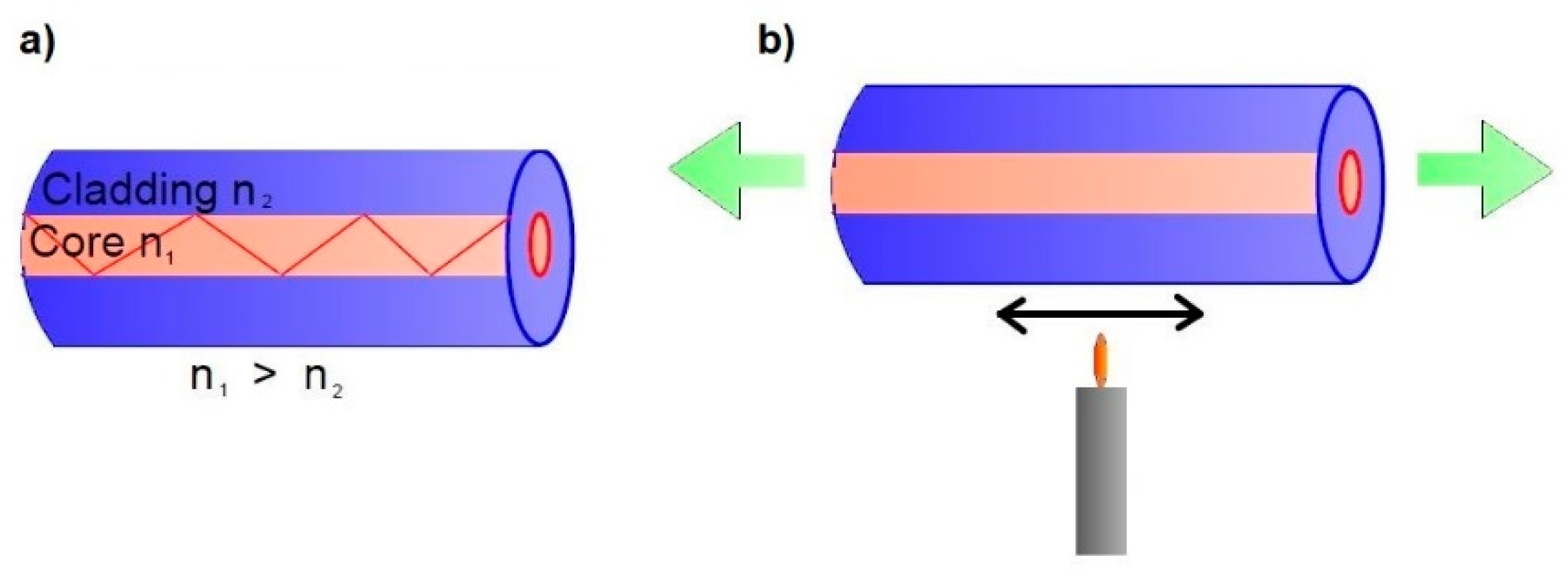
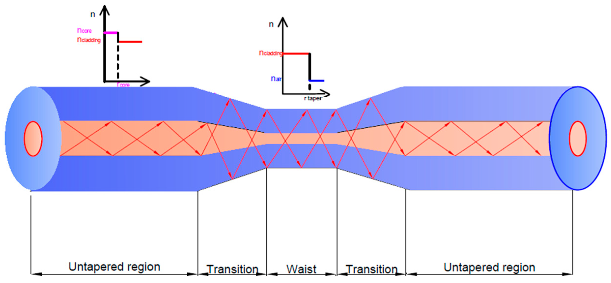
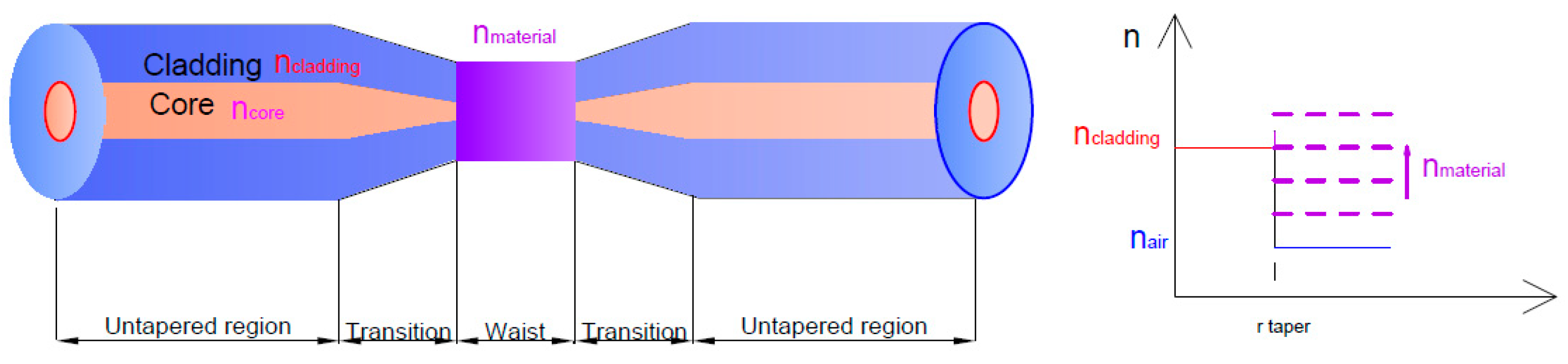
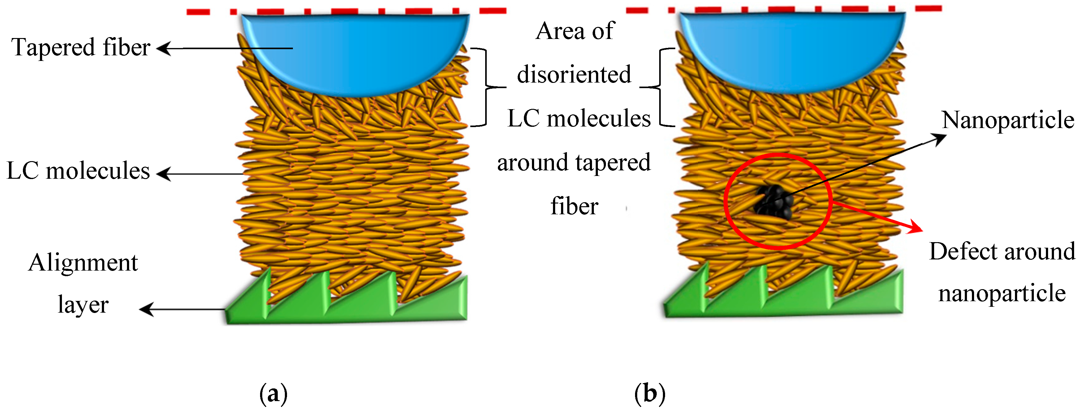
2.1. Propagation of Light in Tapered Optical Fiber with and without Liquid Crystal Cladding
2.2. Materials
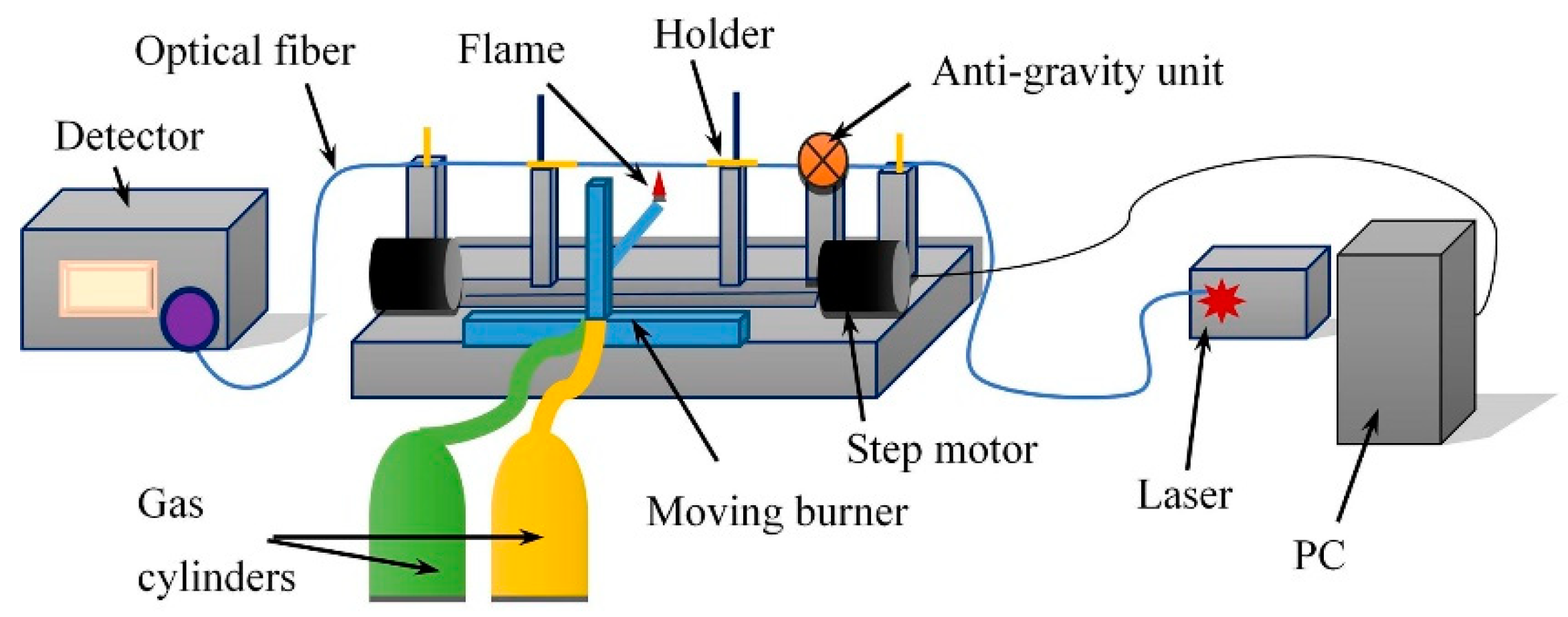
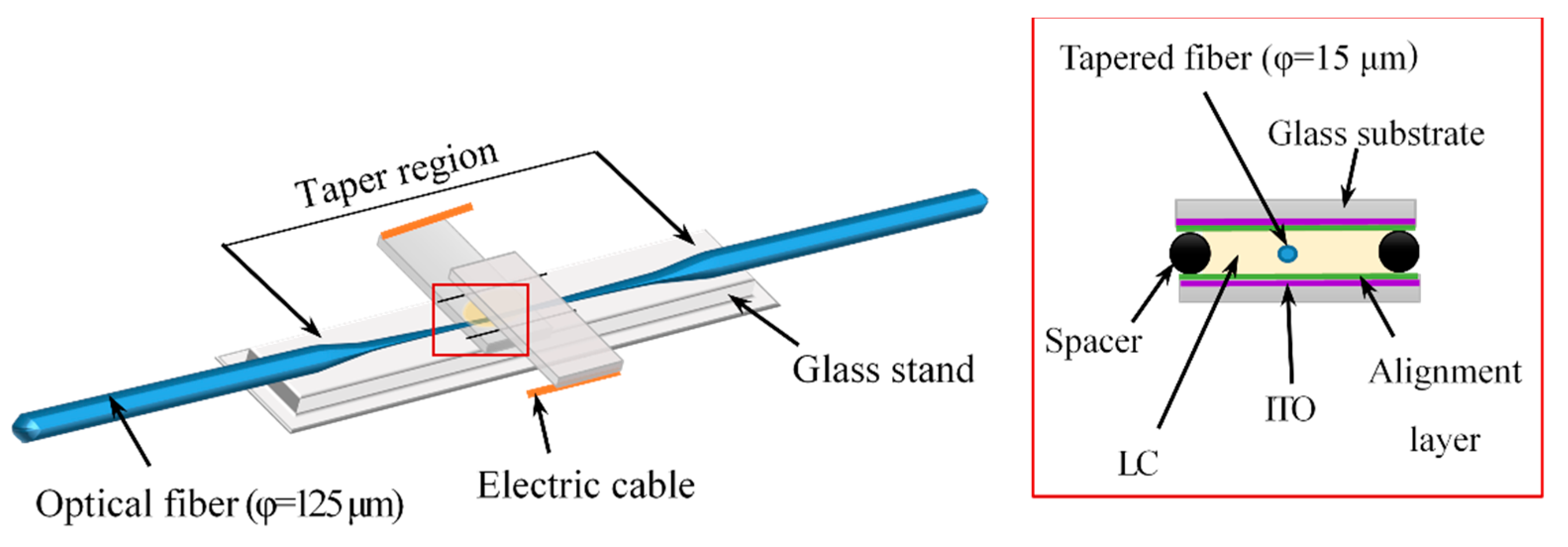
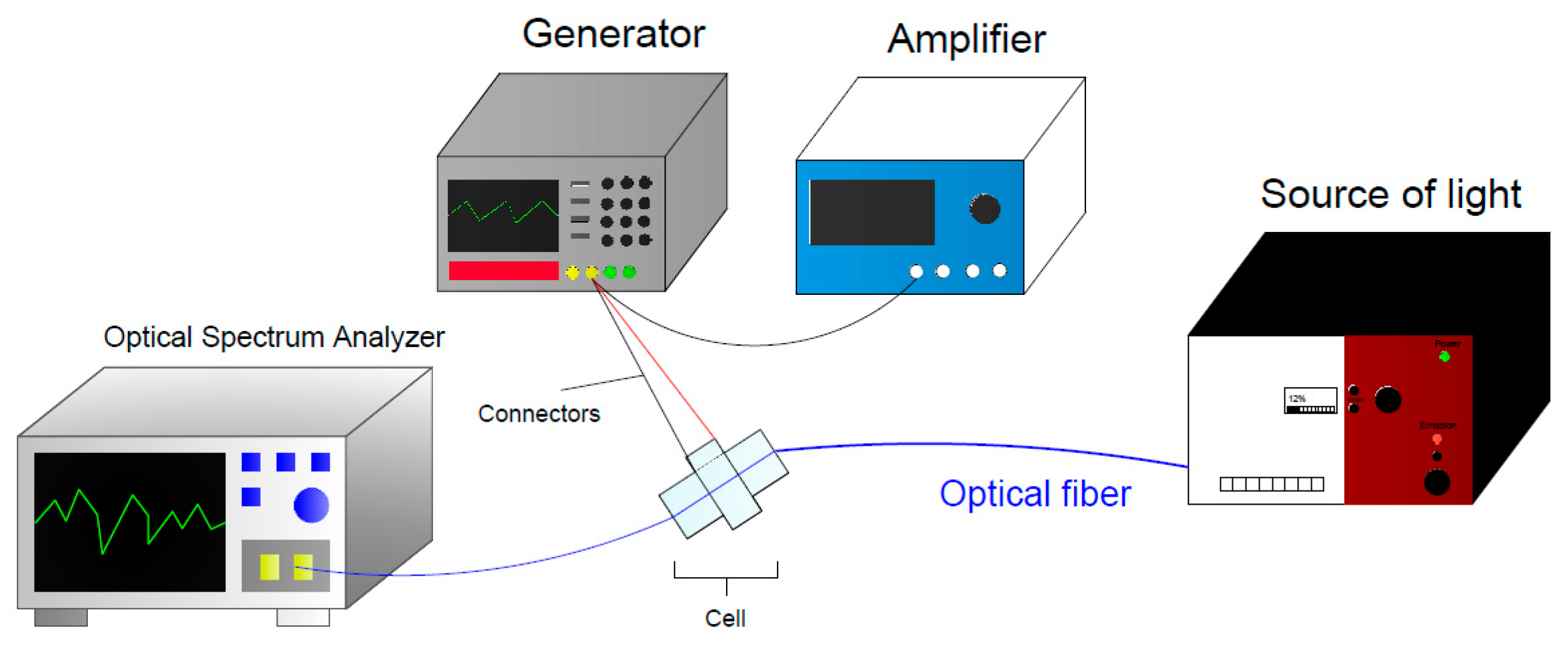
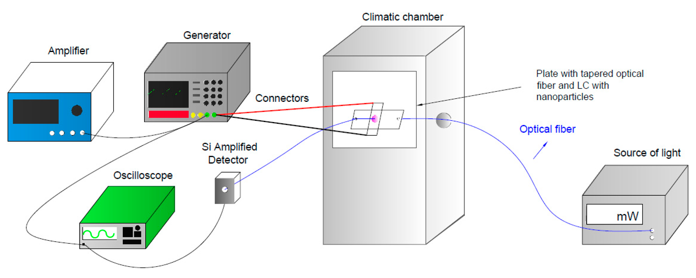
2.3. Technology
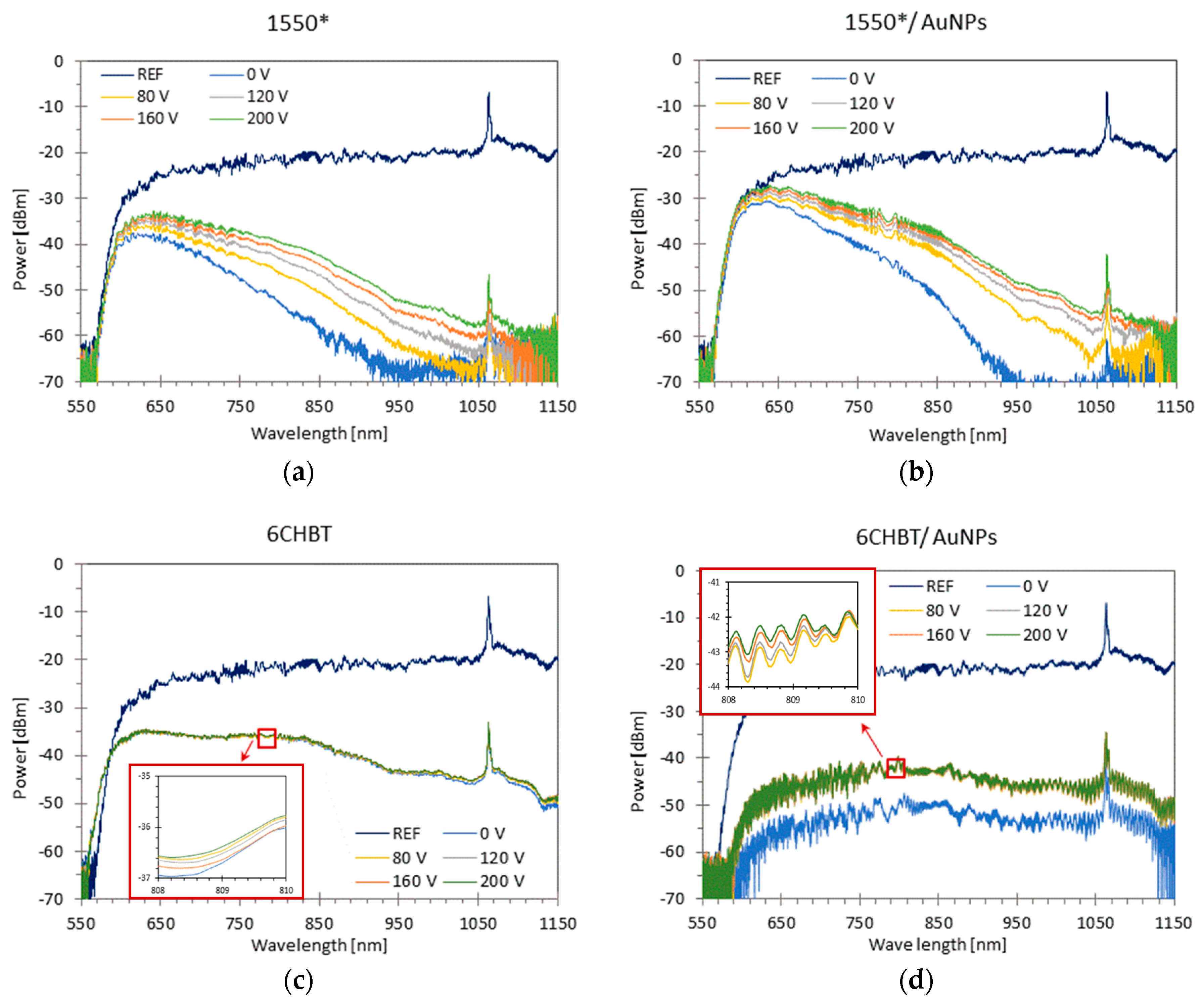
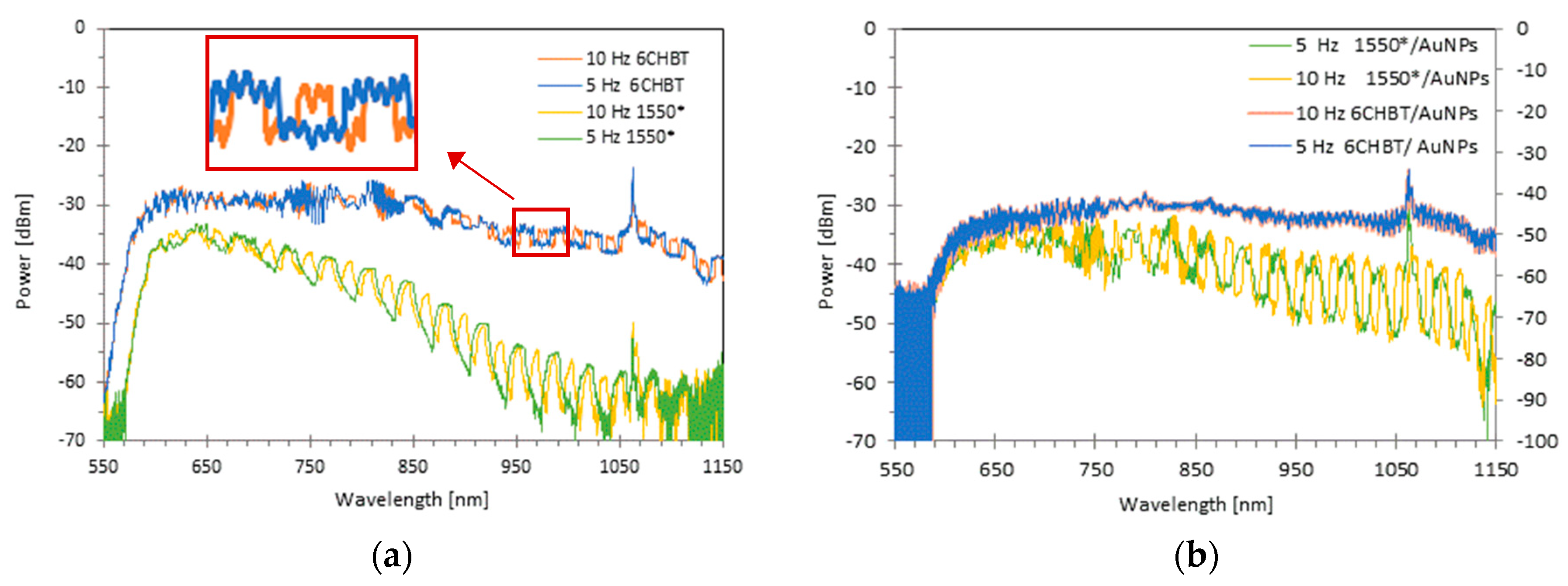
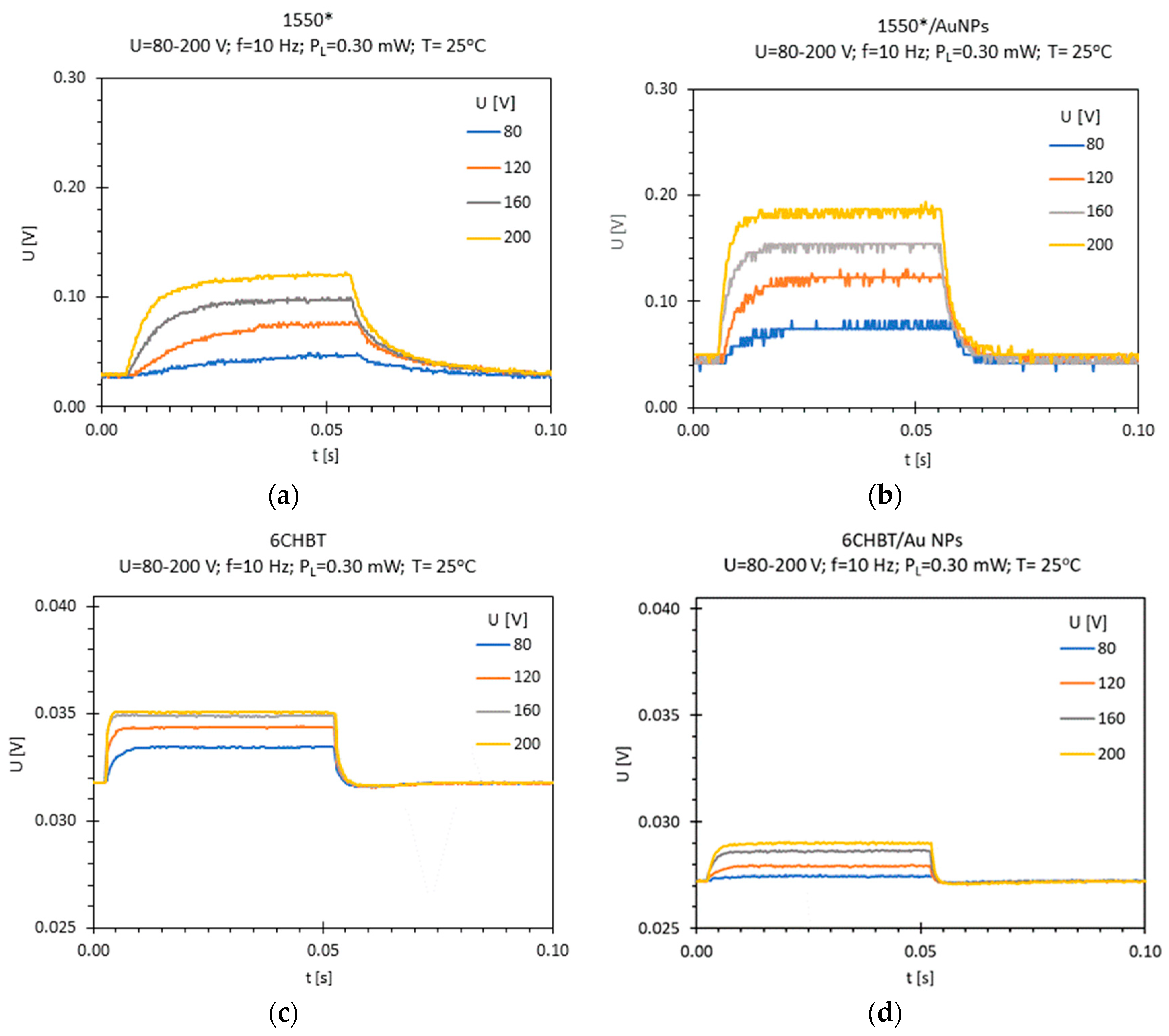
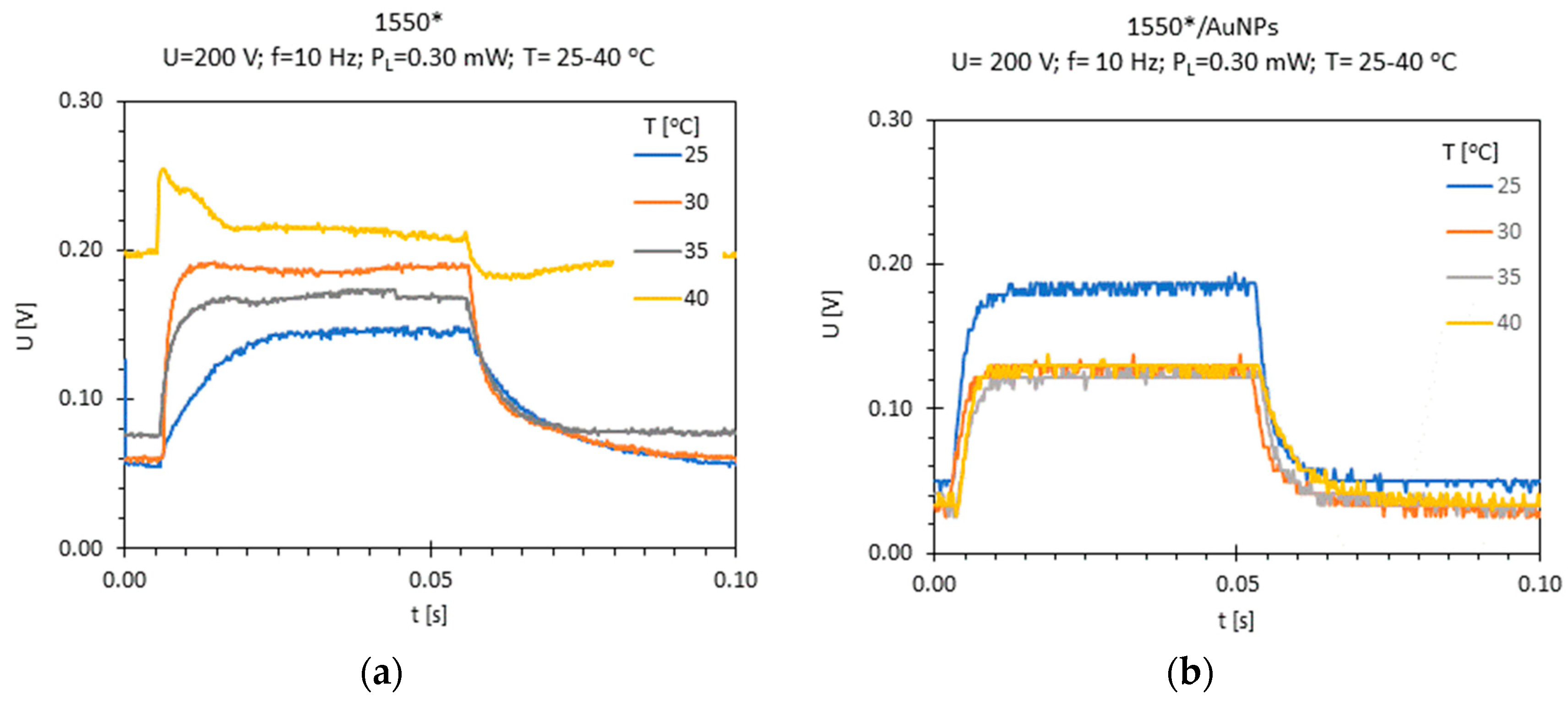
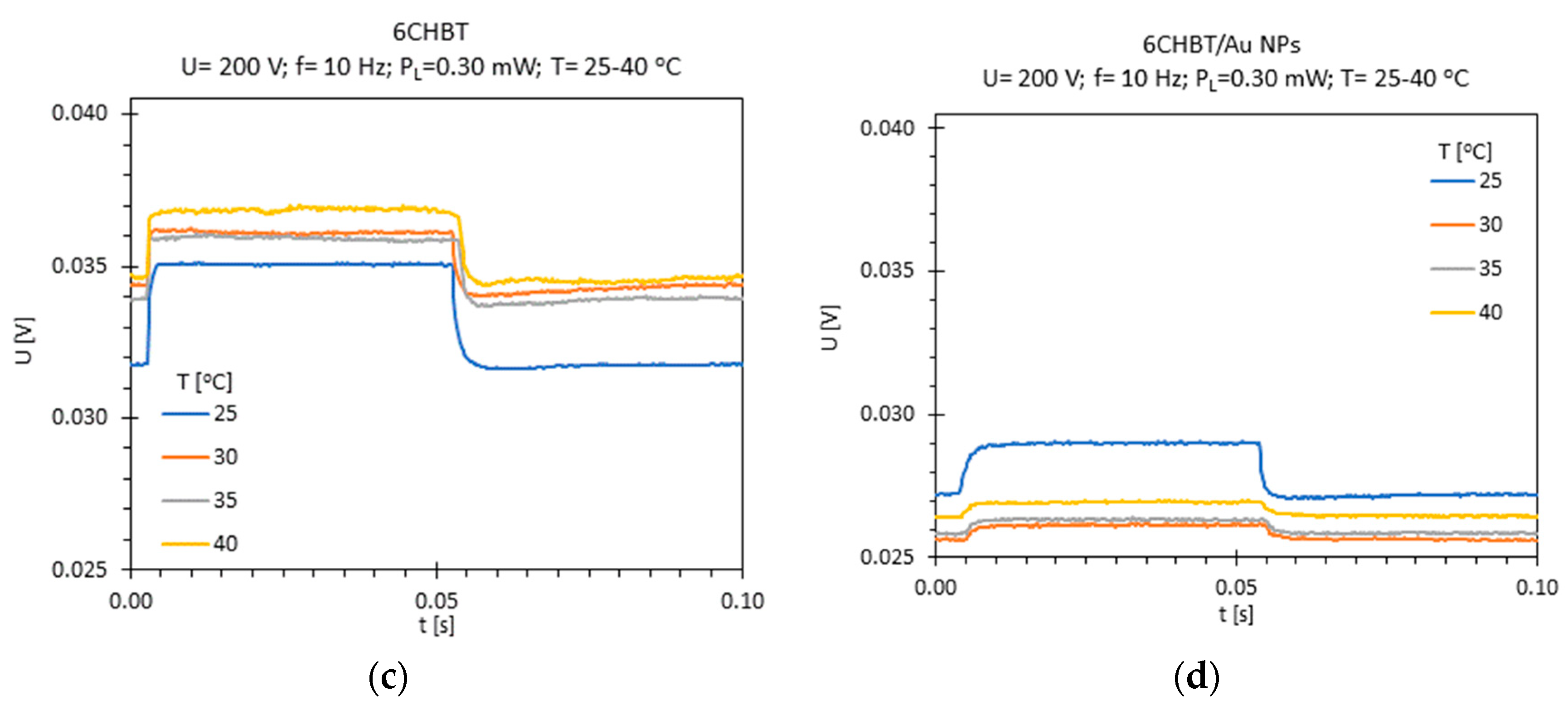
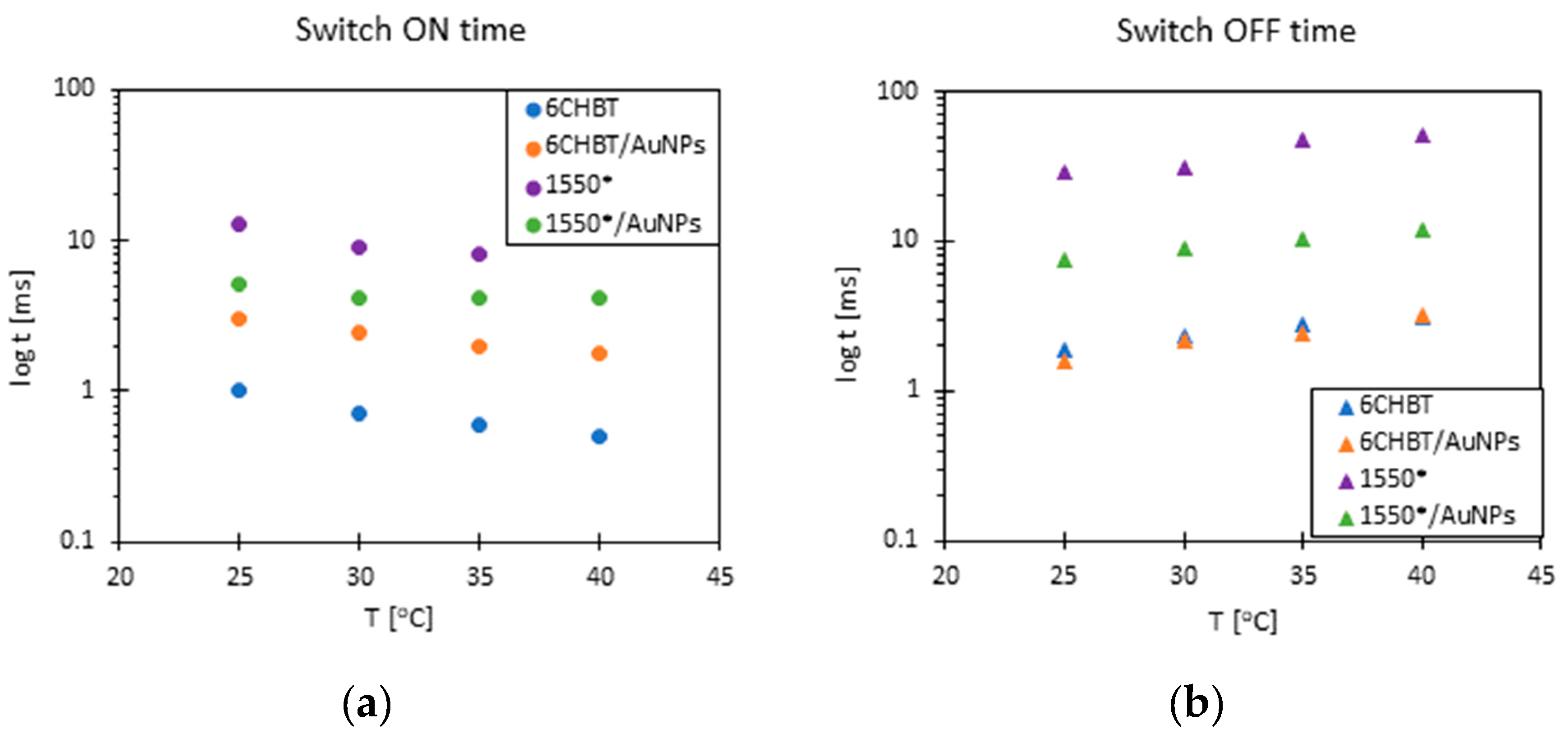
3. Results
4. Conclusions
Author Contributions
Funding
Conflicts of Interest
References
- Nealon, G.L.; Greget, R.; Dominguez, C.; Nagy, Z.T.; Guillon, D.; Gallaniand, J.L.; Donnio, B. Liquid-crystalline nanoparticles: Hybrid designand mesophase structures. Beilstein J. Org. Chem. 2012, 8, 349–370. [Google Scholar] [CrossRef] [PubMed]
- Škarabot, M.; Ryzhkova, A.V.; Muševič, I. Interactions of single nanoparticles in nematic liquid crystal. J. Mol. Liq. 2018, 267, 384–389. [Google Scholar] [CrossRef]
- Hsu, C.J.; Lin, L.J.; Huang, M.K.; Huang, C.Y. Electro-optical Effect of Gold Nanoparticle Dispersed in Nematic Liquid Crystals. Crystals 2017, 7, 287. [Google Scholar] [CrossRef]
- Woliński, T.R.; Siarkowska, A.; Budaszewskia, D.; Chychłowskia, M.; Czapla, A.; Ertman, S.; Lesiak, P.; Rutkowska, K.; Orzechowski, K.; Sala-Tefelska, M.; et al. Recent advances in liquid-crystal fiber-optics and photonics. Proc. SPIE 2017, 10125, 101250W. [Google Scholar] [CrossRef]
- Kowerdziej, R.; Garbat, K.; Walczakowski, M. Nematic liquid crystal mixtures dedicated to thermally tunable terahertz devices. Liq. Cryst. 2018, 45, 1040–1046. [Google Scholar] [CrossRef]
- Sengupta, A. Liquid Crystal Theory. In Topological Microfluidics: Nematic Liquid Crystals and Nematic Colloids in Microfluidic Enviroment; Springer: Basel, Switzeland, 2013; pp. 7–34. [Google Scholar]
- Katsunari, O. Wave Theory of Optical Waveguides. In Fundamentals of Optical Waveguides; Academic Press: Londyn, UK, 2006; pp. 1–12. [Google Scholar]
- Frazão, O.; Santos, J.L.; Araújo, F.M.; Ferreira, L.A. Optical sensing with photonic crystal fibers. Laser Photonics Rev. 2008, 2, 449–459. [Google Scholar] [CrossRef] [Green Version]
- Brambilla, G. Optical fibre nanowires and mikrowires: Review. J. Opt. 2010, 12, 043001. [Google Scholar] [CrossRef]
- Tian, Y.; Wang, W.; Wu, N.; Zou, X.; Wang, X. Tapered Optical Fiber Sensor for Label-Free Detection of Biomolecules. Sensors 2011, 11, 3780–3790. [Google Scholar] [CrossRef] [Green Version]
- Moś, J.E.; Stasiewicz, K.A.; Garbat, K.; Morawiak, P.; Piecek, W.; Jaroszewicz, L.R. Tapered fibre liquid crystal tunable broad band filter. Phys. Scr. 2018, 93, 125002. [Google Scholar] [CrossRef]
- Korec, J.; Stasiewicz, K.A.; Strzeżysz, O.; Kula, P.; Jaroszewicz, L.R. Electro-Steering Tapered Fiber-Optic Device with Liquid Crystal Cladding. J. Sens. 2019, 2019, 1617685. [Google Scholar] [CrossRef]
- Chao, D.; Wang, Q.; Zhao, Y. Electrically tunable long period gratings temperature sensor based on liquid crystal infiltrated photonic crystal fibers. Sens. Actuators A Phys. 2018, 278, 78–84. [Google Scholar]
- Czapla, A.; Bock, W.J.; Woliński, T.R.; Mikulic, P.; Dąbrowski, R.; Nowinowski-Kruszelnicki, E. Electically tunable long-period fiber gratings with low- birefringence liquid crystal near the turn-around point. Opto-Electron. Rev. 2017, 25, 290–295. [Google Scholar] [CrossRef]
- Choudhury, P.K.; Soon, W.K. On the tapered optical fibers with radially anisotropic liquid crystal clad. Prog. Electromagn. Res. 2011, 115, 461–475. [Google Scholar] [CrossRef]
- Wahle, M.; Kitzerow, H.S. Liquid crystal assisted optical fibers. Opt. Express 2014, 22, 262–273. [Google Scholar] [CrossRef] [PubMed]
- Woliński, T.R.; Szaniawska, K.; Ertman, S.; Lesiak, P.; Domański, A.W.; Dąbrowski, R.; Nowinowski-Kruszelnicki, E.; Wojcik, J. Influence of temperature and electrical fields on propagation properties of photonic liquid-crystal fibers. Meas. Sci. Technol. 2006, 17, 985–991. [Google Scholar] [CrossRef]
- Larsen, T.T.; Bjarklev, A. Optical devices based on liquid crystal photonic bandgap fibres. Opt. Express 2003, 11, 2589–2596. [Google Scholar] [CrossRef]
- Veilleux, C.; Lapierre, J.; Jacques, B. Liquid crystal clad tapered fibers. Opt. Lett. 1986, 11, 733–735. [Google Scholar] [CrossRef]
- Veilleux, C.; Black, R.J.; Lapierre, J. Nematic liquid crystal clad tapered optical fiber with temperature sensing properties. J. Appl. Phys. 1990, 67, 6648–6653. [Google Scholar] [CrossRef]
- Dąbrowski, R.; Garbat, K.; Urban, S.; Woliński, T.R.; Dziaduszek, J.; Ogrodnik, T.; Siarkowska, A. Low-birefringence liquid crystal mixtures for photonic liquid crystal fibres application. Liq. Cryst. 2017, 44, 1911–1928. [Google Scholar] [CrossRef]
- Zhang, L.; Lou, J.; Tong, L. Micro/Nanofiber Optical Sensors. Photonic Sens. 2011, 1, 31–42. [Google Scholar] [CrossRef]
- Polynkin, P.; Polynkin, A.; Peyghambarian, N.; Mansuripur, M. Evanescent field-based optical fiber sensing device for measuring the refractive index of liquids in microfluidic channels. Opt. Lett. 2005, 30, 1273–1275. [Google Scholar] [CrossRef] [PubMed]
- Choudhury, P.K.; Soon, W.K. On the transmission by liquid crystal tapered optical fibers. Optik 2011, 122, 1061–1068. [Google Scholar] [CrossRef]
- Laudyn, U.; Rutkowska, K.; Rutkowski, R.T.; Karpierz, M.A.; Woliński, T.R.; Wójcik, J. Nonlinear effects in photonic crystal fibers filled with nematic liquid crystals. Cent. Eur. J. Phys. 2008, 6, 612–618. [Google Scholar] [CrossRef]
- Jadżyn, J.; Hellemans, L.; Czechowski, G.; Legrand, C.; Douali, R. Dielectric and viscous properties of 6CHBT in the isotropic and nematic phases. Liq. Cryst. 2010, 27, 613–619. [Google Scholar] [CrossRef]
- Siarkowska, A.; Chychłowski, M.; Budaszewski, D.; Jankiewicz, B.; Bartosewicz, B.; Woliński, T.R. Thermo- and electro-optical properties of photonic liquid crystal fibers doped with gold nanoparticles. Beilstein J. Nanotechnol. 2017, 8, 2790–2801. [Google Scholar] [CrossRef] [PubMed] [Green Version]
- Budaszewski, D.; Chychłowski, M.; Budaszewska, A.; Bartosewicz, B.; Jankiewicz, B.; Woliński, T.R. Enhanced efficiency of electric field tunability in photonic liquid crystal fibers doped with gold nanoparticles. Opt. Express 2019, 27, 14260–14269. [Google Scholar] [CrossRef] [PubMed]
- Brust, M.; Walker, M.; Bethell, D.; Schiffrin, D.J.; Whyman, R. Synthesis of thiol-derivatised gold nanoparticles in a two-phase liquid-liquid system. J. Chem. Soc. Chem. Commun. 1994, 801–802. [Google Scholar] [CrossRef]
- Stasiewicz, K.A.; Jaroszewicz, L.R. Automatic set-up for advanced optical fiber elements manufacturing. Proc. SPIE 2005, 5952. [Google Scholar] [CrossRef]
- Weglowski, R.; Piecek, W.; Kozanecka-Szmigiel, A.; Konieczkowska, J.; Schab-Balcerzak, E. Poly(esterimide) bearing azobenzene units as photoaligning layer for liquid crystals. Opt. Mater. 2015, 49, 224–229. [Google Scholar] [CrossRef]
- Orlandi, S.; Benini, E.; Miglioli, I.; Evans, D.R.; Reshetnyak, V.; Zannoni, C. Doping liquid crystals with nanoparticles. A computer simulation of effects of nanoparticle shape. Phys. Chem. 2016, 18, 2428–2441. [Google Scholar] [CrossRef]
- Urbanski, M. On the impact of nanoparticle doping on the electro-optic response of nematic hosts. Liq. Cryst. Today 2015, 24, 102–115. [Google Scholar] [CrossRef] [Green Version]


© 2019 by the authors. Licensee MDPI, Basel, Switzerland. This article is an open access article distributed under the terms and conditions of the Creative Commons Attribution (CC BY) license (http://creativecommons.org/licenses/by/4.0/).
Share and Cite
Moś, J.E.; Korec, J.; Stasiewicz, K.A.; Jankiewicz, B.; Bartosewicz, B.; Jaroszewicz, L.R. Research on Optical Properties of Tapered Optical Fibers with Liquid Crystal Cladding Doped with Gold Nanoparticles. Crystals 2019, 9, 306. https://0-doi-org.brum.beds.ac.uk/10.3390/cryst9060306
Moś JE, Korec J, Stasiewicz KA, Jankiewicz B, Bartosewicz B, Jaroszewicz LR. Research on Optical Properties of Tapered Optical Fibers with Liquid Crystal Cladding Doped with Gold Nanoparticles. Crystals. 2019; 9(6):306. https://0-doi-org.brum.beds.ac.uk/10.3390/cryst9060306
Chicago/Turabian StyleMoś, Joanna E., Joanna Korec, Karol A. Stasiewicz, Bartłomiej Jankiewicz, Bartosz Bartosewicz, and Leszek R. Jaroszewicz. 2019. "Research on Optical Properties of Tapered Optical Fibers with Liquid Crystal Cladding Doped with Gold Nanoparticles" Crystals 9, no. 6: 306. https://0-doi-org.brum.beds.ac.uk/10.3390/cryst9060306