Liquid Crystal Based Head-Up Display with Electrically Controlled Contrast Ratio

Department of Electronic Engineering, Shanghai Jiao Tong University, Shanghai 200240, China
*
Author to whom correspondence should be addressed.
Crystals 2019, 9(6), 311; https://0-doi-org.brum.beds.ac.uk/10.3390/cryst9060311
Submission received: 9 May 2019
/
Revised: 7 June 2019
/
Accepted: 14 June 2019
/
Published: 18 June 2019
(This article belongs to the Special Issue Advances in Cholesteric Liquid Crystals)
Abstract
:With the growing demand for driving safety and convenience, Head-Up Displays (HUDs) have gained more and more interest in recent years. In this paper, we propose a HUD system with the ability to adjust the relative brightness of ambient light and virtual information light. The key components of the system include a cholesteric liquid crystal (CLC) film, a geometric phase (GP) liquid crystal lens, and a circular polarizer. By controlling the voltage applied to the GP lens, the contrast ratio of the virtual information light to ambient light could be continuously tuned, so that good visibility could always be obtained under different driving conditions.
1. Introduction
Head-Up Displays (HUDs) have attracted more and more interest recently because of their important role in improving driving safety. A HUD can directly project vital driving information such as speed and navigation into the driver’s eyes without the need to shift one’s sight off the road. Nowadays, HUDs have been integrated into some top-end vehicles. For example, in BMW M5 (an executive car produced by German automotive manufacturer BMW), a HUD is realized by projecting an image onto a translucent TFT (thin-film transistor) display in the windscreen via a specially shaped mirror [1]. More modern implementations and enhancements of HUDs have also been developed. Okumura et al. realized a wide field-of-view HUD using a partial transparent Fresnel reflector as a combiner [2]. Wei et al. proposed a HUD with superior optical performance using three off-axis freeform mirrors [3]. Zhan et al. used GP elements to enhance the performance of HUDs in many aspects [4].
In different driving conditions, the brightness of ambient light may undergo dramatic change, which would affect the visual effects of HUDs. When a car runs in bright sunlight in summer, the virtual information provided by a HUD gets washed out. Increasing the brightness of the HUD may alleviate the problem, but greatly increases power consumption. When a vehicle runs on a dark road at night, the excessive brightness of the HUD may become quite disturbing. Moreover, sometimes, a sudden change in ambient light may occur when, for instance, entering or exiting a tunnel. However, most current HUDs can only adjust the brightness of the virtual image, but cannot control the brightness of the real world scene. To improve visual quality and driving safety, it is highly desirable to realize real-time brightness adaptation for both ambient light and virtual information, and thus ensure the contrast between the two within a reasonable range.
Several approaches have been proposed to achieve transmission control in augmented reality systems. Photochromic materials [5] have excellent dimming capability, but the response time is too slow for real-time operation. The STN (super twisted nematic) guest-host liquid crystal film has also been utilized in combination with a reflective polarizer to control the contrast of the scene [6]. Yet, simultaneous control of real-world-scene transmission and virtual-information brightness has not been demonstrated.
In this paper, we propose a HUD with electrically controlled contrast ratio, based on a cholesteric liquid crystal (CLC) [7,8,9] film, a geometry phase (GP) [10,11,12,13,14] liquid crystal (LC) lens and a circular polarizer. The CLC film here works as a reflective polarizer, which reflects one circular polarization with the same helical sense as the helix of the CLC, and simply transmits the orthogonal circular polarization. The GP LC lens [15,16,17] is a flat-plate diffractive device whose phase profile is generated by spatial variation of the LC directors instead of the optical path distance. Its diffraction efficiency is electrically tunable and is highly polarization-dependent. In our HUD system, by controlling voltage applied to the GP LC lens, the transmittance of the ambient light and the reflectance of the virtual light could be tuned simultaneously, so that the contrast ratio of the two can be controlled in an appropriate range. Therefore, the driver can always see virtual information and road conditions in different driving environments.
2. Principles of the CLC Film and the GP Lens
CLC is also called chiral nematic liquid crystal. Under the action of the chiral dopant, the nematic LC directors rotate along the normal direction of the plane, but in the same layer, all the LC directors are oriented in the same direction as shown in Figure 1a. The axial length over which the LC directors rotate by 180° is half pitch P/2. When light wavelength is within the reflection band of a CLC, the circularly polarized light with the same helical sense would be reflected, while the circularly polarized light with the opposite handedness would be transmitted. For both the reflected and transmitted light, polarization states are unchanged. For example, a right-handed CLC (RHCLC) exhibits a high reflection characteristic for right-handed circular polarization (RCP) and a high transmission characteristic for left-handed circular polarization (LCP) as shown in Figure 1b, and vice versa.
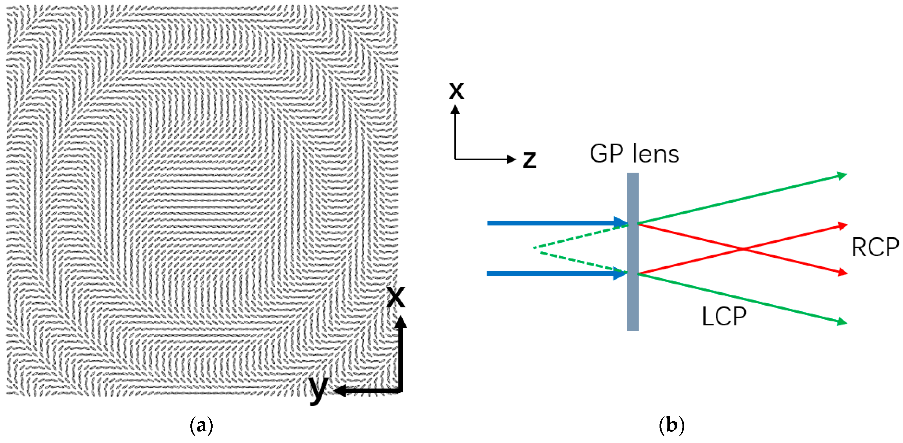
The optic axis (LC directors) of a GP LC element change spatially, and that produces phase modulation for the incident light. The optic axis distribution of a GP lens in the substrate plane (x-y plane) is shown in Figure 2a. The azimuthal angle of the optic axis φ(x, y) changes continuously so that a parabolic phase profile is generated along the radial direction; in the direction perpendicular to the substrate (z-axis direction), the LC directors are uniformly aligned unless voltage is applied. When the incident light is a circular polarization, the output electric field vector after passing through a GP lens can be expressed as in [18]:
where (x, y) is the initial phase of the incident light. The output light consists of two components: a handedness inverted first-order circular polarization and a handedness unchanged zero-order circular polarization. The coefficient η = sin2(Γ/2) is the first-order diffraction efficiency and η0 = cos2(Γ/2) is the zero-order diffraction efficiency, where Γ is the phase retardation. When half-wave retardation is satisfied (Γ =), the first-order efficiency could theoretically reach 100% [13,19]. The phase shift term ±2φ in the first-order indicates that the sign of the additional phase is opposite for LCP and RCP. Therefore, a GP lens converges light of one circular polarization and diverges light of the other as illustrated in Figure 2b.
3. Working Principle of the HUD
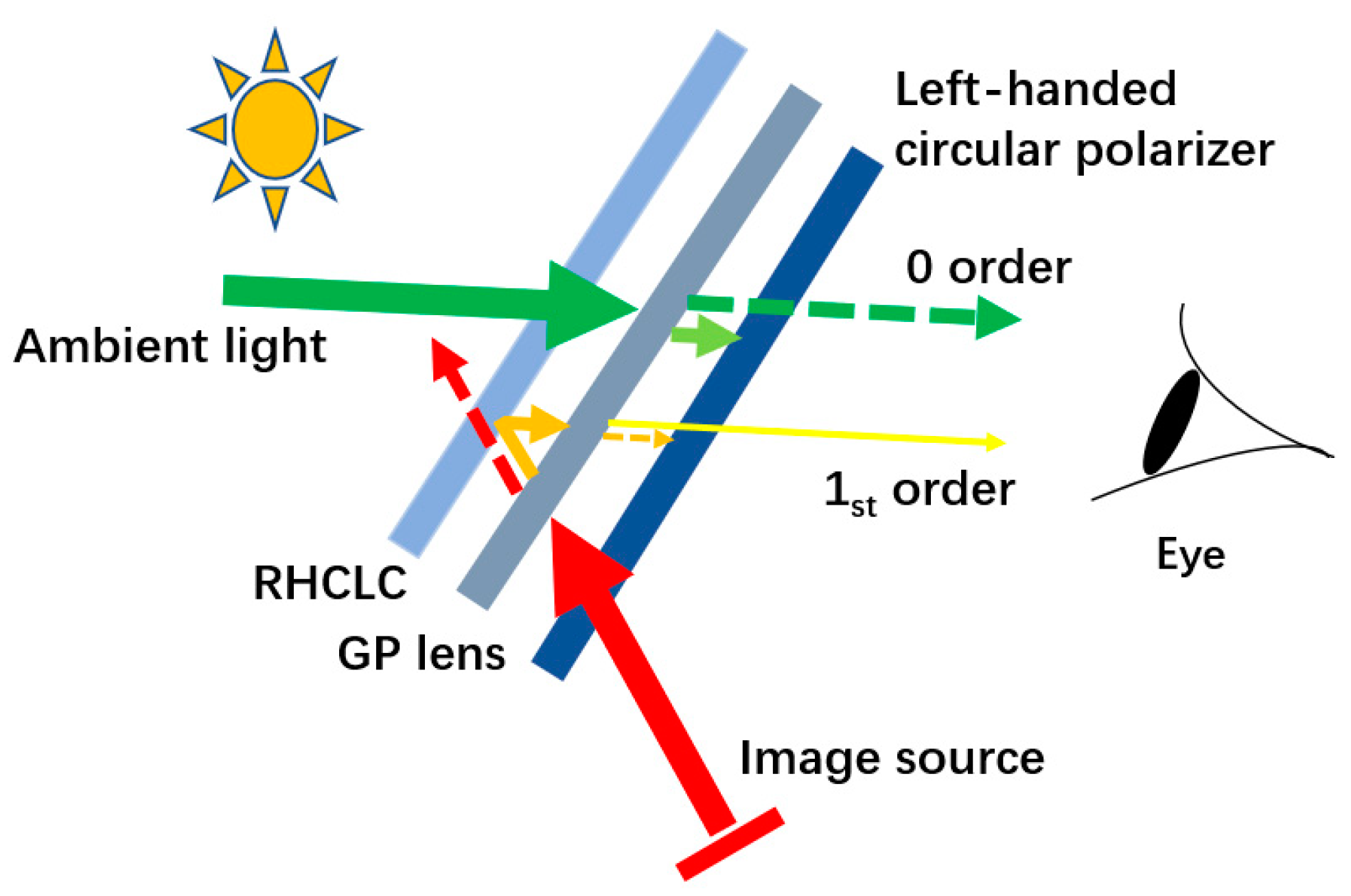
The structural design of the HUD system we propose is shown in Figure 3. It consists of an image source, a broadband left-handed circular polarizer (Edmunds), a GP LC lens, and a RHCLC film. A circular polarizer could be considered as the optical combination of a polarizer and a quarter-wave plate, and in our structure, the polarizer side is facing the driver. The RHCLC is a reflective polarizer, which reflects most RCP and transmits most LCP.
For the virtual information light coming from the image source, it first encounters the left-handed circular polarizer and gets converted into the LCP. Next, the LCP light passes through the GP LC lens and gets diffracted. For this specific GP lens, its phase profile is designed in such a way that it exhibits a positive optical power for LCP light coming from the driver’s side. So the first-order light is converged, and its handedness inversed, while the zero order remains left-handed as shown in Figure 4a. As they further proceed to the RHCLC film, the first order RCP is reflected towards the driver’s side because of chirality match, while the zero order LCP is transmitted into the other side. Upon reflection, the first order light remains to be RCP thanks to the reflectivity characteristic of the CLC.
As the reflected RCP light encounters the GP LC lens for the second time, diffraction occurs again, which decomposes the RCP light into a LCP first-order component and a RCP zero-order component as shown in Figure 4b. Here, because both the light propagation direction and circular polarization handedness are reversed, the optical power of the lens remains positive, resulting in the first order light being even more converged. Eventually, the RCP zero-order is absorbed by the left-handed circular polarizer, while the converged LCP first-order manages to pass it through, and enters the driver’s eye pupil.
For the virtual information light that reached the pupil, it passed through the positive GP lens twice. The effective optical power is approximately twice of that in a single passage. By appropriately choosing the image source location and the focal length of the GP LC lens, the virtual information can be magnified by the system. The diffraction efficiency through the double passage is approximately sin4(Γ/2).
As for the ambient light, first of all, the RCP part of the light is reflected back by the RHCLC film, while the LCP part passes it through and encounters the elements that follow. Similarly, the GP lens diffracts the LCP ambient light into LCP zero-order light and RCP first-order. But the first-order light has diverged now as shown in Figure 4c, because the lens exhibits a negative focal length for LCP light coming from the external side. Finally, the left-handed circular polarizer filters out the RCP first-order, and only allows the LCP zero-order light to pass through.
From what has been discussed above, only the first-order of virtual information light and the zero-order of ambient light entering the human eye. By changing the applied voltage on the GP LC lens, the diffraction efficiencies for the first-order and zero-order will vary. Hence the brightness of the virtual information and ambient light could also be adjusted accordingly.
4. Experiment and Result
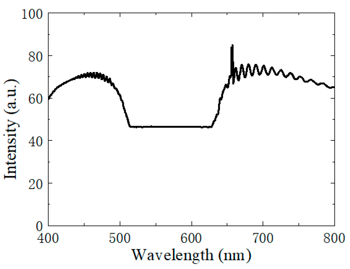
In our experiment, the RHCLC film was prepared by infiltrating an LC mixture containing 97.05 wt.% nematic liquid crystal with a large birefringence Δn ~ 0.4 (Changchun Institute of Optics, Changchun, Jilin, China) and 2.95 wt.% right-handed chiral dopant R5011 (HCCH, Nanjing, Jiangsu, China) into a 10 μm homogeneously aligned cell [20]. Using a high-resolution spectrometer (Ocean Optics, Shanghai, China), the transmittance spectrum of the RHCLC film was measured and shown in Figure 5. One can see that a flat reflection band within which high reflection occurs for RCP light ranges from 513 nm to 630 nm.
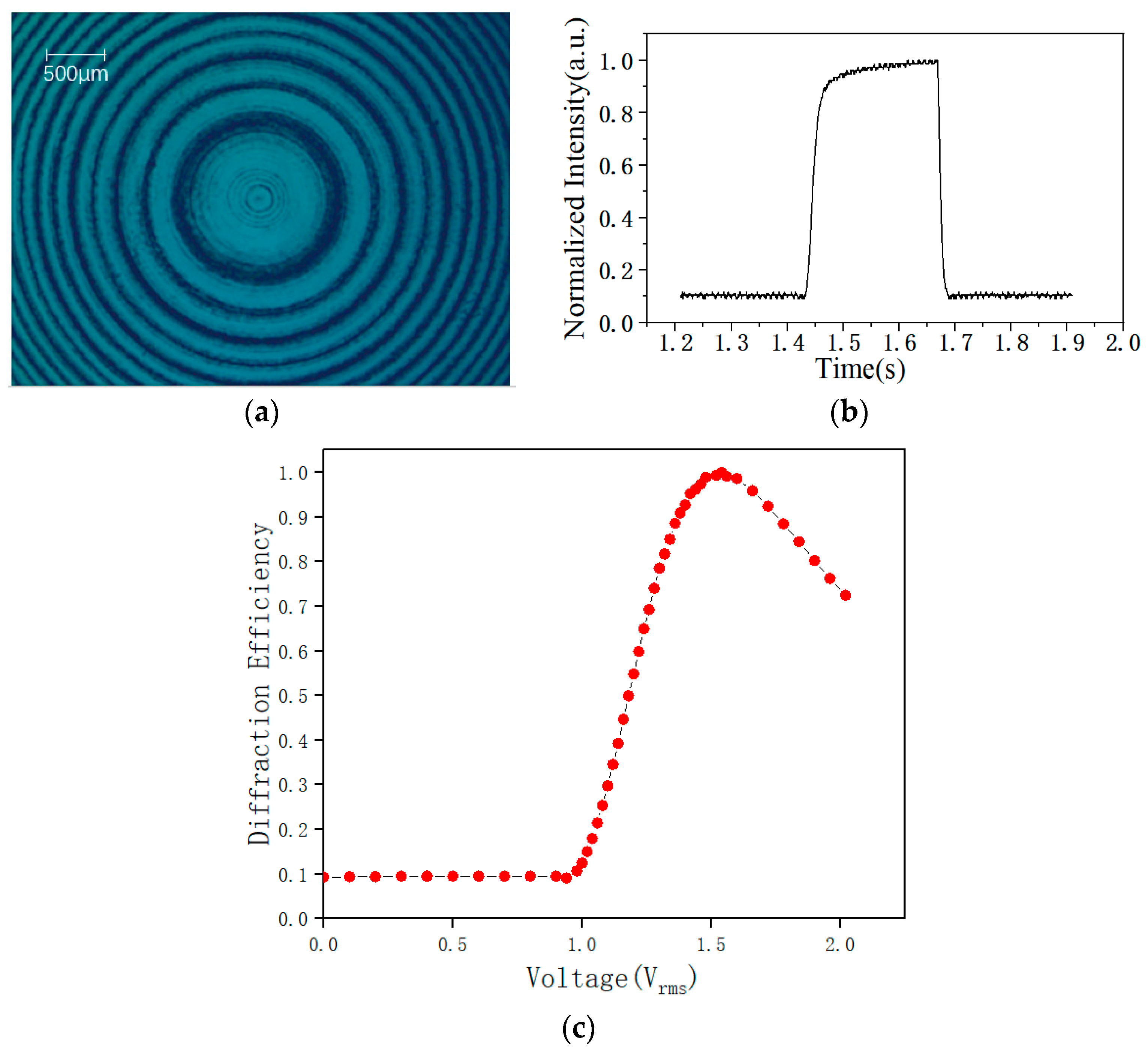
The GP LC lens was fabricated using a non-interferometric single-exposure technique [21]. A 3 μm cell filled with an LC mixture consisted of 99 wt.% E7 (HCCH, Nanjing, Jiangsu, China) and 1 wt.% azo-dye methyl red (MR) (Sigma Aldrich, Shanghai, China). The size of the GP lens in our experiment was 1.5 cm × 0.9 cm. Figure 6a shows the micrograph of the GP lens under crossed polarizers. The total electrical switching time was 37.2 ms (rising time 27.8 ms and decay time 9.4 ms) as shown in Figure 6b. The rise time could be sped up further using the overdrive method [22]. The response time was fast enough to ensure quick contrast ratio adjustment when the ambient brightness changes.
The voltage-dependent-diffraction efficiency (defined as the focused beam intensity divided by the total beam intensity behind the GP LC cell) for the wavelength 633 nm is shown in Figure 6c. Peak diffraction efficiency could be achieved at about 1.6 Vrms. Because the dye dopant MR has considerable absorption in blue and green, we purposely chose the color of virtual information light to be red.
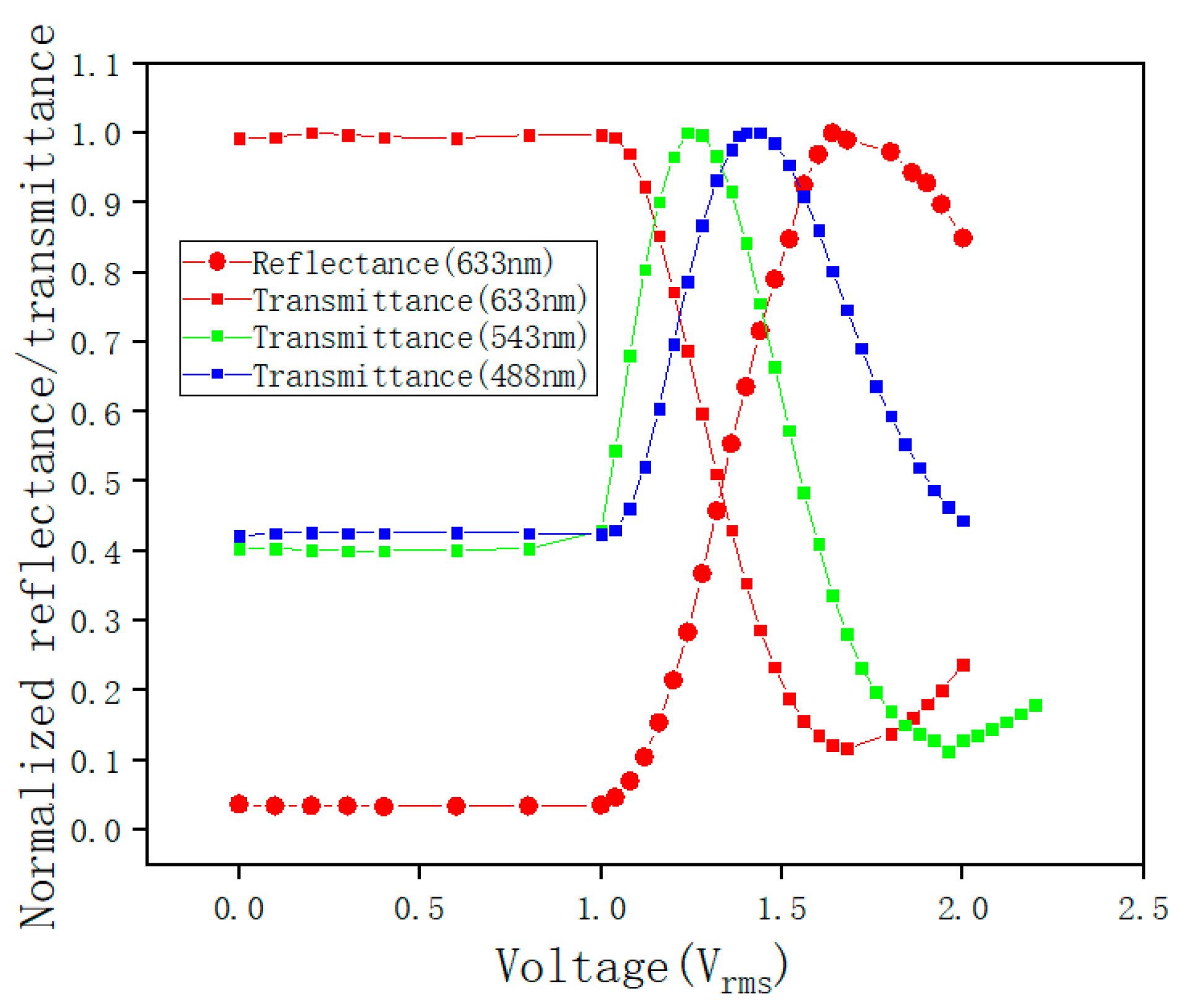
Figure 7 shows the measured reflectance and transmittance of the system at different voltages. Surface reflections caused by the refractive index difference between the LC cell and the air can be reduced by gluing together each device except the image source with glycerin (n ~ 1.47). Since the virtual information is in red, the reflectance was measured using a 633 nm red laser. We also measured the transmittance using 633 nm, 543 nm, and 488 nm lasers to investigate the electro-optical properties of the GP LC lens for the ambient light. From the figure, one can see that for the same wavelength, the increase of reflectance is accompanied by the decrease of transmittance, because they correspond to the first-order and zero-order, respectively. However, due to the material dispersion and wavelength dependence of the GP effect itself, different wavelengths have different diffraction efficiencies. Since the human eye has the greatest visual sensitivity to green light, we take the curve of green light as the main reference. Over a range of voltage variations (approximately from 1.3 Vrms to 1.7 Vrms), the reflectance of the virtual information light increases while the transmittance of the ambient light decreases.
The transmittance curves for red, green, and blue light from the real world are mainly determined by the zero-order diffraction efficiency of the GP lens. Theoretically, when the applied voltage on the GP lens V is lower than the threshold voltage Vth [23], the zero-order diffraction efficiency (η0) of the GP lens can be expressed as η0 = cos2(πΔn(λ)d/λ), where Δn is the birefringence of the LC, d is the cell gap, and λ is the wavelength. Here, d is ~ 3 μm and Δn of E7 for 633 nm is about 0.225, so the phase retardation term πΔn(λ)d/λ is close to π, resulting in maximum efficiency η0 for the red light at zero-voltage state. For green or blue light, πΔn(λ)d/λ deviates from π, hence the transmittance is lower than that of red. In addition, the absorption of MR molecules for green and blue, and the transmittance spectrum of the CLC cell would also affect the absolute values of their transmittance.
An LCD screen, with a red letter “S” in black background, was served as the light source. The distance between the LCD screen and the GP lens was 12cm. The GP lens and the CLC cell were stacked together with an index matching liquid, glycerin. A piece of paper with some black text was placed 23 cm from the CLC cell, on the other side of the system, as the real-world scene. A camera was placed at the pupil position to capture photos. Figure 8 shows the photos taken through the HUD by the camera. When the voltage applied on the GP lens increases gradually, the brightness of “S” increases and that of the background decreases. Because the virtual image is generated at a distance closer than the background, one can see from the figure that when “S” is in focus, the background is blurry as shown in the left part of the pictures, and when the background is in focus, the virtual “S” is blurry as shown in the right part. In real vehicles, when the eye focuses on the road, the road is absolutely clear. So it will not raise safety concerns.
5. Discussion
In our prototype, as the applied voltage increases, the color variation of the background accompanies the change of brightness. That is mainly because the diffraction efficiency of the GP lens is wavelength-dependent. To overcome this problem, one can use a dual-twist-structure GP lens in the system, which can achieve almost achromatic diffraction efficiency [24]. Here, as proof-of-concept verification, only a red virtual image was displayed by our proposed HUD. To realize full-color rendering, we plan to use SD1 [25], a photo-alignment material which has negligible absorption in the visible region, to replace MR in the future. Moreover, the reflection band of the CLC film should also be expanded to cover the entire visible range by using gradient pitch or multilayer methods [26]. Although the wavelength-dependent focal length (f) of GP lenses, which can be approximated by f ∝ 1/λ [23], would inevitably generate different magnifications for different colors, pre-calibration by the software in the image source could provide a simple yet effective solution to this. Considering the exotic features of the proposed HUD system, such as being able to adjust both ambient light and virtual information simultaneously, and the instant response to the applied voltage, it could greatly improve the virtual experience and driving safety. The application of such a display is not limited to HUDs in vehicles, but can also be extended to head-mounted displays for augmented reality.
6. Conclusions
We have proposed a HUD system for automobile applications, which can adjust the relative light intensity of ambient light and virtual light by changing the applied voltage. It provides a solution for HUDs to enable good visibility of both virtual information and real-world scenes under various driving conditions. The experimental results confirmed that dynamic control of brightness contrast could be realized within a voltage range of 1.68 Vrms to 1.96 Vrms. In the future, the visual performance of the HUD could be further improved by expanding the reflection bandwidth of the CLC film and eliminating chromatic aberration of the GP lens.
Author Contributions
Conceptualization—Y.L. (Yan Li) and Y.L. (Yueda Liu); Formal analysis—Y.L. (Yueda Liu), Q.C. and S.L.; Funding acquisition—Y.L. (Yan Li) and Y.S.; Investigation—Y.L. (Yueda Liu); Project administration—Y.L. (Yan Li); Supervision—Y.L. (Yan Li); Validation—Y.L. (Yueda Liu); Writing – original draft—Y.L. (Yueda Liu); Writing, Review, and Editing—Y.L. (Yan Li).
Funding
National Natural Science Foundation of China (61727808); Shanghai Jiao Tong University (YG2016QN37); Key Lab of Advanced Optical Manufacturing Technologies of Jiangsu Province, and Key Lab of Modern Optical Technologies of Education Ministry of China, Soochow University (KJS1607).
Conflicts of Interest
The authors declare no conflict of interest.
References
- How to Use BMW M Head-up Display. Available online: https://www.bmw-m.com/en/topics/magazine-article-pool/how-to-use-bmw-m-head-up-display.html (accessed on 16 June 2019).
- Okumura, H.; Hotta, A.; Sasaki, T.; Horiuchi, K.; Okada, N. Wide field of view optical combiner for augmented reality head-up displays. In Proceedings of the 2018 IEEE International Conference on Consumer Electronics, Las Vegas, NV, USA, 12–14 January 2018; pp. 1–4. [Google Scholar]
- Wei, S.; Fan, Z.; Zhu, Z.; Ma, D. Design of a head-up display based on freeform reflective systems for automotive applications. Appl. Opt. 2019, 58, 1675–1681. [Google Scholar] [CrossRef] [PubMed]
- Zhan, T.; Lee, Y.-H.; Xiong, J.; Tan, G.; Yin, K.; Yang, J.; Liu, S.; Wu, S.-T. High-efficiency switchable optical elements for advanced head-up displays. J. Soc. Inf. Disp. 2019, 27, 223–231. [Google Scholar] [CrossRef]
- Wirnsberger, G.; Scott, B.J.; Chmelka, B.F.; Stucky, G.D. Fast response photochromic mesostructures. Adv. Mater. 2000, 12, 1450–1454. [Google Scholar] [CrossRef]
- Zhu, R.; Chen, H.; Kosa, T.; Coutino, P.; Tan, G.; Wu, S.T. High-ambient-contrast augmented reality with a tunable transmittance liquid crystal film and a functional reflective polarizer. J. Soc. Inf. Disp. 2016, 24, 229–233. [Google Scholar] [CrossRef]
- Wu, S.-T.; Yang, D.-K. Reflective Liquid Crystal Displays; Wiley: New York, NY, USA, 2001. [Google Scholar]
- Mitov, M.; Dessaud, N. Going beyond the reflectance limit of cholesteric liquid crystals. Nat. Mater. 2006, 5, 361–364. [Google Scholar] [CrossRef] [PubMed]
- Yang, D.-K.; Wu, S.-T. Fundamentals of Liquid Crystal Devices; Wiley: New York, NY, USA, 2007. [Google Scholar]
- Anandan, J. The geometric phase. Nature 1992, 360, 307–313. [Google Scholar] [CrossRef]
- Pancharatnam, S. Generalized theory of interference, and its applications. Proc. Indian Acad. Sci. A 1956, 44, 398–417. [Google Scholar] [CrossRef]
- Berry, M.V. Quantal phase factors accompanying adiabatic changes. Proc. R. Soc. Lond. 1987, A392, 45–57. [Google Scholar]
- Marrucci, L.; Manzo, C.; Paparo, D. Pancharatnam-Berry phase optical elements for wavefront shaping in the visible domain: Switchable helical modes generation. Appl. Phys. Lett. 2006, 88, 221102. [Google Scholar] [CrossRef]
- Zheng, G.; Muhlenbernd, H.; Kenney, M.; Li, G.; Zentgraf, T.; Zhang, S. Metasurface holograms reaching 80% efficiency. Nat. Nanotechnol. 2015, 10, 308–312. [Google Scholar] [CrossRef] [PubMed]
- Zhan, T.; Lee, Y.-H.; Wu, S.-T. High-resolution additive light field near-eye display by switchable Pancharatnam–Berry phase lenses. Opt. Express 2018, 26, 4863–4872. [Google Scholar] [CrossRef] [PubMed]
- Tan, G.; Zhan, T.; Lee, Y.-H.; Xiong, J.; Wu, S.-T. Polarization-multiplexed multiplane display. Opt. Lett. 2018, 43, 5651–5654. [Google Scholar] [CrossRef] [PubMed] [Green Version]
- Lee, Y.-H.; Tan, G.; Yin, K.; Zhan, T.; Wu, S.-T. Compact see-through near-eye display with depth adaption. J. Soc. Inf. Disp. 2018, 26, 64–70. [Google Scholar] [CrossRef]
- Kim, J.; Li, Y.; Miskiewicz, M.N.; Oh, C.; Kudenov, M.W.; Escuti, M.J. Fabrication of ideal geometric-phase holograms with arbitrary wavefronts. Optica 2015, 11, 958–964. [Google Scholar] [CrossRef]
- Nikolova, L.; Ramanujam, P.S. Polarization Holography; Cambridge University Press: Cambridge, UK, 2009. [Google Scholar]
- Chen, Q.; Peng, Z.; Li, Y.; Liu, S.; Zhou, P.; Gu, J.; Lu, J.; Yao, L.; Wang, M.; Su, Y. Multi-plane augmented reality display based on cholesteric liquid crystal reflective films. Opt. Express 2019, 27, 12039–12047. [Google Scholar] [CrossRef] [PubMed]
- Li, Y.; Liu, Y.; Li, S.; Zhou, P.; Zhan, T.; Chen, Q.; Su, Y.; Wu, S.-T. Single-exposure fabrication of tunable Pancharatnam-Berry devices using a dye-doped liquid crystal. Opt. Express 2019, 27, 9054–9060. [Google Scholar] [CrossRef] [PubMed] [Green Version]
- Wu, S.T. Nematic liquid crystal modulator with response time less than 100 μs at room temperature. Appl. Phys. Lett. 1990, 57, 986–988. [Google Scholar] [CrossRef]
- Lee, Y.-H.; Tan, G.; Zhan, T.; Weng, Y.; Liu, G.; Gou, F.; Peng, F.; Tabiryan, N.V.; Gauza, S.; Wu, S.-T. Recent progress in Pancharatnam–Berry phase optical elements and the applications for virtual/augmented realities. Opt. Data Process. Storage 2017, 3, 79–88. [Google Scholar] [CrossRef]
- Oh, C.; Escuti, M.J. Achromatic diffraction from polarization gratings with high efficiency. Opt. Lett. 2008, 33, 2287–2289. [Google Scholar] [CrossRef] [PubMed]
- Chigrinov, V.G.; Kwok, H.; Yip, W.C.; Kozenkov, V.M.; Prudnikova, E.K.; Tang, B.Z.; Salhi, F. New photo-aligning and photo-patterning technology: Superthin internal polarizers, retarders, and aligning layers. In Proceedings of the International Symposium on Optical Science and Technology, San Diego, CA, USA, 11 December 2001; pp. 117–132. [Google Scholar]
- Mitov, M. Cholesteric Liquid Crystals with a Broad Light Reflection Band. Adv. Mater. 2012, 24, 6260. [Google Scholar] [CrossRef] [PubMed]
Figure 1.
(a) Schematic diagram of the director configuration of a CLC; (b) Polarization-selective reflectivity of a CLC film.
Figure 1.
(a) Schematic diagram of the director configuration of a CLC; (b) Polarization-selective reflectivity of a CLC film.

Figure 2.
(a) Schematic distribution of LC directors in a GP lens; (b) Polarization dependency of a GP lens.
Figure 2.
(a) Schematic distribution of LC directors in a GP lens; (b) Polarization dependency of a GP lens.

Figure 3.
System design of the proposed augmented reality display.

Figure 4.
Virtual information light passing through the GP lens twice (a) the first time; (b) the second time; (c) Ambient light passing through the GP lens. The solid arrows represent first-order diffracted light, and the dashed arrows are zero-order light.
Figure 4.
Virtual information light passing through the GP lens twice (a) the first time; (b) the second time; (c) Ambient light passing through the GP lens. The solid arrows represent first-order diffracted light, and the dashed arrows are zero-order light.

Figure 5.
Transmittance spectrum of the RHCLC film.

Figure 6.
GP lens (a) optical micrograph under crossed polarizers; (b) response time; and (c) voltage-dependent first-order diffraction efficiency.
Figure 6.
GP lens (a) optical micrograph under crossed polarizers; (b) response time; and (c) voltage-dependent first-order diffraction efficiency.

Figure 7.
Voltage-dependent reflectance (632 nm laser) and transmittance (633 nm, 543 nm, and 488 nm lasers) of the system.
Figure 7.
Voltage-dependent reflectance (632 nm laser) and transmittance (633 nm, 543 nm, and 488 nm lasers) of the system.

Figure 8.
Photos focused on the virtual-information image and the background, respectively, at different voltages (a) 1.68 Vrms, (b) 1.80 Vrms, and (c) 1.96 Vrms.
Figure 8.
Photos focused on the virtual-information image and the background, respectively, at different voltages (a) 1.68 Vrms, (b) 1.80 Vrms, and (c) 1.96 Vrms.

© 2019 by the authors. Licensee MDPI, Basel, Switzerland. This article is an open access article distributed under the terms and conditions of the Creative Commons Attribution (CC BY) license (http://creativecommons.org/licenses/by/4.0/).
Share and Cite
MDPI and ACS Style
Liu, Y.; Li, Y.; Chen, Q.; Li, S.; Su, Y. Liquid Crystal Based Head-Up Display with Electrically Controlled Contrast Ratio. Crystals 2019, 9, 311. https://0-doi-org.brum.beds.ac.uk/10.3390/cryst9060311
AMA Style
Liu Y, Li Y, Chen Q, Li S, Su Y. Liquid Crystal Based Head-Up Display with Electrically Controlled Contrast Ratio. Crystals. 2019; 9(6):311. https://0-doi-org.brum.beds.ac.uk/10.3390/cryst9060311
Chicago/Turabian StyleLiu, Yueda, Yan Li, Quanming Chen, Sida Li, and Yikai Su. 2019. "Liquid Crystal Based Head-Up Display with Electrically Controlled Contrast Ratio" Crystals 9, no. 6: 311. https://0-doi-org.brum.beds.ac.uk/10.3390/cryst9060311
Note that from the first issue of 2016, this journal uses article numbers instead of page numbers. See further details here.