Femtosecond Laser Pulses Amplification in Crystals

National Institute for Nuclear Physics and Engineering, Extreme Light Infrastructure-Nuclear Physics, Reactorului Street 30, 077125 Magurele, Romania
Crystals 2019, 9(7), 347; https://0-doi-org.brum.beds.ac.uk/10.3390/cryst9070347
Submission received: 22 April 2019
/
Revised: 24 June 2019
/
Accepted: 1 July 2019
/
Published: 5 July 2019
(This article belongs to the Special Issue Laser Crystals)
Abstract
:This paper describes techniques for high-energy laser pulse amplification in multi-PW femtosecond laser pulses. Femtosecond laser pulses can be generated and amplified in laser media with a broad emission spectral bandwidth, like Ti:sapphire crystals. By chirped pulse amplification (CPA) techniques, hundred-Joule amplified laser pulses can be obtained. Multi-PW peak-power femtosecond pulses are generated after recompression of amplified chirped laser pulses. The characteristics and problems of large bandwidth laser pulses amplification in Ti:sapphire crystals are discussed. An alternative technique, based on optical parametric chirped pulse amplification (OPCPA) in nonlinear crystals, is presented. Phase-matching conditions for broad bandwidth parametric amplification in nonlinear crystals are inferred. Ultra-broad phase matching bandwidth of more than 100 nm, able to support the amplification of sub-10 fs laser pulses, are demonstrated in nonlinear crystals, such as Beta Barium Borate (BBO), Potassium Dideuterium Phosphate (DKDP), and Lithium Triborate (LBO). The advantages and drawbacks of CPA amplification in laser crystals and OPCPA in nonlinear crystals are discussed. A hybrid amplification method, which combines low-medium energy OPCPA in nonlinear crystals with high energy CPA in large aperture laser crystals, is described. This technique is currently used for the development of 10-PW laser systems, with sub-20 fs pulse duration and more than 1012 intensity contrast of output femtosecond pulses.
1. Introduction
In continuous-wave, free-running and Q-switched pulsed laser oscillators, the output laser is the result of the interference of a number of longitudinal laser modes with discrete frequencies, determined by the resonance frequencies of the optical resonator, and random phase relations. Longitudinal oscillating modes are supplied by the energy accumulated on the upper laser level of the laser active medium. For their amplification, they compete one against the other in the optical resonator. Only few strong-gain longitudinal modes are able to exceed the oscillation threshold. The result is a quasi-monochromatic laser emission. Ultrashort laser pulses with pulse width in the picosecond-femtosecond range can be generated by the mode-locking technique. A well-defined phase relationship is established between the longitudinal modes from the fluorescence spectral bandwidth of a laser medium, all longitudinal modes have the same initial phase factor. The random fluctuations of the laser emission are transformed in a powerful well-defined single pulse circulating in the laser generator with an ultrashort duration. The mode-locked laser pulse duration is inversely proportional to the spectral bandwidth Bν which includes all phase-locked longitudinal modes [1].
where N is the number of phase-locked longitudinal modes of the optical resonator and Δν is the frequency separation between two adjacent modes. Ultra-short pulse duration represents the Fourier transform from the frequency domain in the time domain. In case of a pulsed laser with Gaussian temporal and spectral profiles, the shortest full-width half-maximum (FWHM) mode-locked pulse duration is given by:
The value, which can be obtained if all longitudinal modes from the frequency bandwidth are phase locked, represents the pulse-width at the Fourier Transform Limit (FTL).
In the case of laser media frequently used in the years ‘70, like Nd:YAG crystals and Nd-doped glasses, the mode locking regime was obtained by passive mode-locking using saturable absorbers and active mode-locking based on amplitude and frequency modulation of optical radiation inside the laser resonators [1]. As the emission spectral bandwidths of these active media are relatively narrow, sub-nanometer for Nd:YAG crystals and nanometers for Nd-doped glasses, their mode-locked pulse duration is in the range of few-ten picoseconds and picosecond, respectively. In a typical oscillator resonator, hundreds of longitudinal modes are phase coupled in a Nd:YAG mode-locked laser, whereas thousands of longitudinal modes contribute to the picosecond pulse generation in Nd-doped glasses.
Femtosecond laser pulses can be generated and amplified in laser crystals with broad emission bandwidths, in the range of ten-hundred nanometers. Section 2 of the paper is devoted to femtosecond laser pulses amplification in laser crystals. For laser pulses amplification, a population inversion between upper and lower laser energy levels of the crystal is required. It is realized by optical pumping of the active ions of the laser crystal to the upper metastable laser energy level. An incoming laser pulse, with photons energy equal to the energy difference between the laser energy levels, can be amplified by the stimulated emission radiation. Specific problems of femtosecond pulses amplification are discussed. Chirped pulse amplification (CPA) in laser crystals is presented as an appropriate technique for high power femtosecond laser systems development. Spectroscopic and lasing properties of the Ti:sapphire, the laser crystal with the broadest emission bandwidth, are described. Typical configurations of the Ti:sapphire amplifiers are presented. Technical difficulties encountered in the all Ti:sapphire high power femtosecond laser systems are emphasized. The advantages and drawbacks related to the amplification of broad-bandwidth laser pulses in PW-class all Ti:sapphire laser systems are discussed.
An alternative method for femtosecond laser pulses amplification, based on optical parametric amplification (OPA) in nonlinear crystals is presented in Section 3 of the paper. Under phase-matching condition, for an appropriate orientation of the nonlinear crystal, a broad parametric gain bandwidth can be obtained. Phase-matching conditions for a parametric amplification process with an ultra-broad phase-matching bandwidth in nonlinear crystals are inferred. More than 100 nm gain bandwidth can be reached in BBO, DKDP, and LBO nonlinear crystals. For high energy broad-bandwidth laser pulse amplification in nonlinear crystals, the currently used solution is the optical parametric chirped pulse amplification (OPCPA). The typical configuration of OPCPA stages and technical difficulties related to high energy OPCPA are described. The advantages and drawbacks of OPCPA in nonlinear crystals are also discussed. A hybrid amplification technique, which combines the low-medium energy amplification by OPCPA in nonlinear crystals with high energy OPA in laser crystals, considered as a suitable solution for 10-PW laser systems development, is described in the Section 4 of the paper.
2. Femtosecond Laser Pulses Amplification in Laser Crystals
2.1. Femtosecond Laser Pulses Generation
The femtosecond pulse generation has been obtained in laser oscillators based on solid-state laser media with a very large fluorescence band-width in the range of ten-hundred nanometers. In this case, hundreds of thousands and even more longitudinal modes of oscillation are phase-locked. There is a high discrimination between the peak intensity of the mode-locked laser pulse and the continuous wave intensity of a certain laser oscillator:
where N is the number of phase-locked longitudinal modes.
The refractive index in a medium with a nonlinear refractive index depends on the optical radiation intensity according to the relation:
For a high intensity laser beam with a variable intensity profile, for example a Gaussian spatial profile, an intensity dependent graded-index lens is formed. By this effect, called Kerr-lens effect, the high intensity laser radiation is focused towards the central axis of the propagating beam. The contrast between the intensity of a mode-locked laser pulse and the continuous wave radiation intensity is very high in the case of laser crystals with a broad emission bandwidth of tens-hundred nanometer and with hundreds of thousands oscillating transversal modes. Due to the Kerr-lens effect, the transmission through a small-diameter aperture is higher for the very intense beam of a mode locked pulse compared with the low-intensity beam of a continuous-wave laser emission. By transmission through an aperture, the power dependent change of the spatial profile of the beam is transformed into an amplitude modulation. This technique, termed as Kerr-Lens Mode-locking (KLM), provides an efficient method for phase-locking of longitudinal modes of oscillation and large spectral bandwidth femtosecond pulses generation [1].
Spectroscopic properties of a few representative laser crystals able to generate femtosecond laser pulses in KLM oscillators are described in the Table 1. Pump wavelengths have been specified considering the available pump lasers.
In order to generate a femtosecond laser pulse, an essential requirement is to compensate for the positive phase dispersion of the spectral components, engendered by the radiation propagation through the laser crystal in the femtosecond oscillator resonator. A pair of prisms and chirped mirrors [1] inside the resonator are the mostly used methods to generate the appropriate negative dispersion which compensate for the positive dispersion.
A spectral bandwidth and pulse autocorrelation chart of a femtosecond laser pulse generated by a Ti:sapphire femtosecond oscillator, with a pair of prisms inside the optical resonator for phase dispersion compensation, are shown in Figure 1. The ultra-broad spectral bandwidth and sub-10 fs pulse duration of a Ti:sapphire femtosecond oscillator with chirped mirrors for phase dispersion compensation are presented in Figure 2. Both oscillators are currently running at extreme light infrastructure-nuclear physics (ELI-NP), Bucharest-Magurele.
2.2. Nanosecond Pulses Amplification in Laser Crystals
The amplifier laser systems with nanosecond pulses are based on direct amplification of laser pulses. The energy gain of a single-pass laser amplifier is given by the Equation [1,2]:
where Fin is the input pulse fluence (energy per surface unit), is the saturation fluence, h is the Planck’s constant, is the laser frequency, σ is the amplifying transition cross section, is the small signal (low level input fluence, Fin << Fsat) exponential gain, nν the population inversion density, la the amplifying medium length.
For high input fluence level, Fin > Fsat, the energy gain depends quasi-linearly on the laser medium length:
Nearly all accumulated laser energy on the upper laser level is extracted from the laser crystal. The amplified output fluence Fout is given by:
where Fac is the accumulated energy available for laser amplification in the laser medium volume per unit of input surface (accumulated fluence).
The highest gain factor is obtained for exponential gain at very small signal fluence (Figure 3a). The extraction efficiency of the accumulated laser energy becomes significant when the input pulse fluence is near the saturation fluence (Figure 3b). The radiation fluence in a laser amplifier is restricted by the surface and bulk laser induced damage threshold (LIDT) of the amplifying laser crystal.
2.3. Specific Problems of Ultrashort Laser Pulses Amplification
The LIDT fluence on a laser medium surface decreases with the pulse duration τp in the nanosecond-picoseconds range according to a square root variation law:
In the ps-fs range, an approximate cubic root dependence of could be considered.
In the ultrashort laser pulse regime, particularly for femtosecond pulses, the surface LIDT of a certain laser crystal significantly decreases compared to the nanosecond pulse regime. On the other hand, unlike the nanosecond pulse amplification, there is a significant variation of the refractive index due to the very high intensity of the laser radiation. A variable spatial intensity beam profile, with a high peak intensity in the central part of the beam, induces a Kerr lens effect followed by the beam self-focusing and damages inside the optical components of the amplifiers. The nonlinear index for the Ti:sapphire crystal used in femtosecond laser amplifiers is . The saturation fluence of Ti:saphire crystals is approximately 0.9 J/cm2. For a femtosecond pulse with τp = 25 fs FWHM pulse duration, I = 3.6 × 10¹³ W/cm2. According to the Equation (4), near the saturation fluence, the refractive index increases from the initial low-intensity value of n0 = 1.76 up to the high-intensity refractive index n(I) = 1.94.
The additional phase, accumulated due to the intensity dependence of the refractive index (4) and due to the spatial variation of the laser beam intensity, induces wavefront distortions according to the B integral calculated over the beam propagation length L:
The acceptable wavefront distortions entail to a laser amplifier the condition B < 1, which is practically impossible to satisfy in case of high intensity femtosecond laser pulses propagation through the amplification system [3].
Due to these undesirable effects, the direct amplification of femtosecond laser pulses in laser crystals is limited to very low energy levels (nJ–μJ). For high energy systems, direct amplification of femtosecond pulses would be possible only by using huge-aperture optical components, beyond the limits imposed by the manufacturing technologies and costs of fabrication.
The appropriate proposed solution was to stretch the ultra-short pulses generated by laser oscillators in the range of hundred-picoseconds up to nanosecond, to amplify them in some amplifier stages and to re-compress the amplified laser pulses down to a pulse duration similar to the initial one. In a stretcher with diffraction gratings, the optical path of red spectral components are shorter compared to the path of blue optical components [3,4]. The blue optical components are delayed compared to the red ones. Through the amplifier stages, the stretched pulse propagates with the red spectral components travelling in the pulse leading edge. In the temporal compressor, the red spectral components are delayed to compensate for the stretcher dispersion. This method called chirped pulse amplification (CPA) was proposed for the first time in 1985 [5] (Figure 4). It is currently used in all high energy femtosecond laser systems based on laser crystals amplification.
Especially in case of high energy amplifier systems, there are many passes of the amplified stretched pulses through the amplifying laser crystals. To get re-compressed amplified laser pulses with a pulse duration close to the femtosecond oscillator pulse-width, the pulse broad spectral bandwidth and phase relation between spectral components (flat phase in the spectral bandwidth) must be preserved. For tightly focusing the amplified laser beam, wavefront distortions, generated by the thermal and nonlinear optical effects in the laser crystals, must be preserved in the limits imposed by the low value of the B integral. Due to the amplified spontaneous emission, it is a real challenge to deliver laser radiation with a high-intensity contrast between output femtosecond pulses and background radiation.
2.4. Femtosecond Pulses Amplification in Ti:Sapphire Laser Crystals
Due to its very broad gain bandwidth, Ti:sapphire (Ti:Al2O3) is the most widely used laser crystal for femtosecond pulses generation and chirped pulse amplification. In this material, a Ti3+ ion is substituted for an Al3+ ion in Al2O3. Laser crystals consist of sapphire doped with 0.03–0.25% Ti3+ by weight. The Ti:sapphire laser combines a broad tuning range with a large stimulated emission cross-section. The great interest in this material arises from the broad vibronic fluorescence band between 670–1070 nm, with the peak gain curve approximately 790 nm wavelength (Figure 5) [6].
The energy levels of the ground state T and excited state E of titanium ions are the result of the interaction of the 3d electron of Ti3+ with the surrounding oxygen ions in the crystal lattice. The Ti:sapphire crystal exhibits a broad absorption band in the blue-green region of the visible spectrum with a peak of approximately 490 nm (Figure 5 and Figure 6a). The absorption of pump light causes transitions from the ground state T to the excited state E, as indicated in Figure 6a by the vertical transition from A (E1 in Figure 6b) to B (E4 in Figure 6b) [7]. The excited Ti3+ are very quickly displaced to a new C equilibrium position by exciting vibrations (phonons) in the surrounding lattice. The Gaussian-shaped A and C curves represent the probability of finding the Ti3+ at a particular position in the lowest vibrational state of T and E energy levels. The C energy state represents the upper laser level (E3 in Figure 6b). The transition from C to D shows the emission of light in the near-infrared emission band. This light emission terminates on D vibrational levels of the ground state, which represent the lower laser level (E2 in Figure 6b). Both B to C and D to A non-radiative transitions have very fast relaxation times, τ43 and τ21, in the range of 0.1 ps. Under these conditions, because the emission terminates on unpopulated vibrational energy levels, a population inversion on the upper laser level, necessary for laser amplification, can be easily achieved. Unlike these fast vibration transitions, the spontaneous lifetime τ32 of the ion population in the metastable upper laser level E3 is about 3.2 μs. The coupling of the electronic energy levels of the Ti3+ ions with the vibrational energy levels of the sapphire lattice is the essential feature of the vibronic Ti:sapphire laser emission. The laser transition to a large spread of vibrational levels of the T potential gives rise to a large fluorescence bandwidth, as shown in Figure 5.
Apart from favorable spectroscopic and lasing properties, one other advantage of Ti:sapphire are the material properties of the sapphire host itself, namely very high thermal conductivity, chemical inertness and mechanical rigidity. Some significant properties of Ti:sapphire laser crystals are listed in the Table 2 [8].
Since early experiments and characterization of Ti:sapphire laser crystals in the 1980s, different methods were used for crystal growing. The Czochralski method [9], heat exchange method (HEM) [10,11], and temperature gradient technique [10,11] are the mostly used methods. At present, large size Ti:sapphire crystals, up to 200 mm clear aperture, are commercially available for high energy amplifiers of multi-PW femtosecond laser systems [11,12,13] (Figure 7).
The laser pulse amplification in Ti:sapphire crystals is the result of the stimulated laser transition from the upper laser level to the lower laser level, under the inversion population condition between laser energy levels, in the presence of an input laser pulse with the photon quanta energy identical to the energy difference between laser energy levels. To achieve the population inversion, active Ti ions are optically pumped on the upper laser energy level. The fluorescence lifetime determines the available time for the pump source to create and store the population inversion on the upper laser level. Due to the relatively short fluorescence lifetime compared to other solid-state laser media, like Nd:YAG crystals (230 μs) and Nd:glasses (in the range of 300–350 μs, depending on the glass type), the optical pumping of Ti:sapphire crystals with flash-lamps represents a difficult task. Diode pumped frequency doubled continuous wave Nd:doped crystal lasers with output power in the range of 4–6 W [1,14,15] are currently used for pumping the Ti:sapphire femtosecond oscillators, which are running with nano-Joule laser pulse energy at high repetition rate (in the range of 80 MHz). In the high energy CPA laser systems, the duration of the laser pulses to be amplified is usually approximately one nanosecond. Ti:sapphire amplifiers with mJ pulse energy, kHz repetition rate, are usually pumped by, frequency doubled diode pumped acousto-optically Q-switched Nd:YAG, Nd:YLF lasers. Frequency doubled, flash lamp pumped nanosecond oscillator-amplifier Nd:YAG (532 nm) and Nd:glass (527 nm) lasers are used for optical pumping of high energy amplifiers of Ti:sapphire TW-PW femtosecond laser systems [16]. Both pump pulse duration and amplified pulse duration are much shorter than the microseconds excited ions lifetime on the upper laser level. By an appropriate nanosecond accuracy synchronization of green pump lasers with near-infrared seed laser pulses, practically the whole accumulated laser energy on the upper level is available for amplification.
Quanta energy of optical pump radiation is higher than quanta energy of the amplified laser pulses, . Compared to the absorbed pump laser energy, the available energy for laser pulse amplification is reduced by the quantum defect factor, . The quantum efficiency of the amplification process, namely the ratio of pumped ions effectively available for stimulated transitions, which are not relaxed by other types of transitions to the ground energy level, is [6]. Under these conditions, the available energy for laser amplification in the crystal volume with a unit of surface face area of an end-pumped laser crystal, , is given by , where is the pump laser fluence and is the absorption ratio of the pump laser energy in the crystal. The highest amplification factor, G0, is obtained for a very low seed fluence (Fin << Fsat):
where is the local population inversion effectively involved in the amplification by stimulated emission and la is the crystal length. The value of G0 is limited by the laser induced damage threshold (LIDT) of the Ti:sapphire crystal in the pump laser field. The LIDT of Ti:sapphire crystals for the green radiation domain, in the range of ten-nanosecond pulse duration, is considered about 10 J/cm2. For a safe operation of laser systems, the pump fluence is usually restricted to 2 J/cm2. For a Ti:sapphire crystal, one face pumped by a 532 nm wavelength nanosecond Nd:YAG laser, = 0.9, the highest gain factor for one-pass through the crystal is G0 ≈ 1.7 at 1 J/cm2 pump fluence and G0 ≈ 2.3 at 1.5 J/cm2 pump fluence.
For a significant value of the input pulse fluence relative to the saturation fluence, the gain factor G can be calculated using the Equation [17]:
To reach the multi-PW peak power of re-compressed femtosecond laser pulses, the oscillator nJ pulse energy must be amplified with more than eleven order of magnitudes up to hundred-Joule pulse energy. Approximately 40–50 passes through Ti:sapphire amplifying crystals are necessary to reach the hundred-Joule energy level in a multi-PW class femtosecond laser system. For energy amplification from nJ to mJ level, with approximately six orders of magnitude, regenerative amplifiers are frequently used. A simplified configuration of a regenerative amplifier is shown in the Figure 8. The Ti:sapphire crystal is pumped by a continuous wave green laser, for example, a frequency doubled Nd:YAG laser at 532 nm wavelength. The nJ-energy stretched pulse, with orthogonal linear polarization on the laser plane, is injected in the optical resonator of the regenerative amplifier by using a polarizer (POL1). The incident pulse is captured in the resonator by rotating with 90° its linear polarization after a double pass through the activated quarter-wavelength Pockels cell PC1. The trapped laser pulse is amplified by many passes through the Ti:sapphire crystal, typically 15–19 round-trips in the resonator, until its amplification is saturated, usually in the range of mJ pulse energy. When the traveling pulse reaches the saturated energy level, the quarter-wavelength Pockels cell PC2 is activated, the pulse polarization is rotated by 90°, and the amplified pulse is extracted by the POL2 polarizer.
In multi-PW laser systems, an amplification chain which consists in a couple of multi-pass amplifiers, each of them with 2–6 passes through the Ti:sapphire laser crystal, is necessary to further amplify mJ-energy pulses generated by regenerative amplifiers up to the hundred-Joules pulse energy [3,18,19]. A typical configuration of a multi-pass high energy laser pulse amplifier, with an end-pumped Ti:sapphire crystal disk, is shown in Figure 9.
As the excited Ti ions lifetime on the upper laser level of the Ti:sapphire crystal is approximately 3.2 μs, the required accuracy of electronic synchronization of nanosecond pump lasers with the 800 nm amplified laser pulses is in the range of few-ns. Considering the sub-nanosecond time-jitter of the nanosecond pulses generated by electro-optically and acousto-optically Q-switched pump lasers, this accuracy can be easily attained.
To avoid the laser induced damage of Ti:sapphire crystals, the fluence of large bandwidth, 800 nm central wavelength stretched pulses of ~1 ns pulse duration, is restricted to less than 1 J/cm2. For 1-PW femtosecond laser systems, considering a recompressed amplified pulse duration in the range of 20–25 fs and ~70% energy conversion efficiency of the temporal compressor, more than 30 J amplified pulse energy in Ti:sapphire crystals of final amplifiers is required. Ti:sapphire crystals with more than 80 mm clear aperture are necessary for safe operation. More than 300 J pulse energy can be attained in the final amplifier of 10-PW class laser systems. In this case, Ti:sapphire crystals with ~200 mm clear aperture are necessary for safe operation.
2.5. Technical Difficulties Encountered by Amplification of Large Bandwidth Femtosecond Laser Pulses in High Power All Ti:Sapphire Laser Systems
The stimulated emission cross-section of the Ti-sapphire crystals has the highest value in the range of 790 nm (emission central wavelength) and decreases to the reddest and bluest wings of the spectral fluorescence bandwidth. The amplification gain is highest near the emission central wavelength too [20]. Consequently, for each amplification to pass through a Ti:sapphire crystal, the output pulse spectrum becomes narrower compared to the input spectrum. For many passes through the amplifying crystals, due to the gain narrowing effect, the amplified pulse spectrum will be significantly narrower than the initial one. This effect can be observed especially in the regenerative amplifiers where the number of passes through the Ti:sapphire crystals is in the range of 30–38 (Figure 10a).
In the high energy Ti:sapphire laser amplifiers, the fluence of the amplified pulses is in the range of the saturation fluence. Almost all accumulated laser energy, Eac, on the upper laser level of the Ti:sapphire crystal can be extracted and added to the input pulse energy, Ei. The red spectral components are travelling in the front edge of the stretched pulse, whereas the blue components are displayed in the trailing edge. In the amplifiers working near the saturation regime, the population inversion of the upper laser level is significantly depleted by the first coming red components. The amplification factor of the red spectral components will be higher than the the blue spectral components, which encounter a lower population inversion. The result is a red shifting of the output spectrum associated with a spectrum narrowing too (Figure 10a,b). By reducing the amplified pulse spectral band, both gain narrowing and red shifting contributes to the increase of the recompressed amplified pulse duration. Selective reflective filters, designed with a low reflectance in the red section of the spectrum and a higher reflectance in the blue section of the spectrum, can be installed between high energy amplifiers of a multi-PW CPA laser system to manage the spectrum of the amplified stretched laser pulses [21]. Every following amplification stage compensates for the energy losses in the previous selective filter. Besides the spectral bandwidth for the generation of ultra-short amplified laser pulses, it is of crucial importance for the capability to compensate for the phase dispersion in the optical components of the laser system.
The intensity contrast of the amplified femtosecond pulses is determined by the ratio between the recompressed pulse peak intensity and the picoseconds background radiation. After optical pumping of the Ti:sapphire crystal, before the arrival of the laser pulse which is amplified by stimulated emission, the upper laser level is depopulated by spontaneous emission. The amplified spontaneous emission (ASE) in its way through the Ti:sapphire laser crystals contributes to the decrease of the intensity contrast in the picoseconds range prior to the main femtosecond pulse. More than 1011–1012 intensity contrast of amplified femtosecond pulses is required by many of scientific applications of multi-PW laser systems.
Dissipated heat in the laser crystal is the result of the quantum defect. The thermal loading of the Ti:sapphire crystals pumped by Nd-doped green lasers is approximately 34% from the absorbed pump energy. The thermal effect induces a thermal lens in the laser crystal, beam wavefront distortions and phase dispersions of the spectral components of the large bandwidth laser pulses. The result is a poor beam focusing and an increase of the recompressed pulse duration.
Special techniques are currently used in high power all Ti:sapphire laser amplifier systems for the improvement of the recompressed amplified femtosecond pulses characteristics. Some of the frequently used techniques are: saturable absorbers for intensity contrast improvement [22]; acousto-optic programmable dispersive filters (AOPDF) for spectral phase and spectral intensity control [23]; cross-polarized wave (XPW) generation for both intensity contrast improvement and spectrum broadening [24,25]; deformable mirrors to compensate for wavefront distorsions [26,27].
In the high energy multi-PW class laser amplifiers, where more than 100 mm diameter clear aperture Ti:sapphire laser disks are used, a high transversal laser gain can be reached. The accumulated laser energy on the upper laser level can be depleted by the transversal lasing effect which hampers the normal amplification of the stretched nanosecond laser pulses. In a Ti:sapphire crystal disk, pumped by end faces, the maximum transversal gain is attained near the pump face, where the highest density of the absorbed pump radiation and the population inversion is reached (Figure 11). The pump energy is limited by the maximum admissible transversal gain which can be attained without transversal lasing.
Considering a pump laser with a flat spatial profile of the beam intensity, the transversal gain near the pumped end-face of the Ti:sapphire crystal disk is given by [19,28]:
where α is the absorption coefficient of the pump radiation in the crystal, D is the diameter of the pumped area, Fp(0) is the pump fluence at the input face. To decrease the transversal gain, laser crystals with a low absorption coefficient, implicitly with a low Ti ions doping density, could be used. In this case, thicker laser crystals are necessary to preserve >90% absorption of the pump radiation in the laser crystal.
Cooling liquids with the refractive index matched to the refractive index of the Ti:sapphire crystals represent a good solution to suppress the parasitic lasing in case of PW-class laser systems, where the beam diameters of the pump pulse and amplified pulse are in the range of 60–80 mm [29]. It is possible to achieve perfect index matching at one single wavelength, for example the 800 nm central wavelength of Ti:sapphire spectrum. For other wavelengths from the large bandwidth Ti:sapphire spectrum, there is a small variation of the refractive index of the liquid and the crystal. For this reason, the efficiency of this method is restricted up to a certain value of the transversal gain. By refractive-index matching, the reflectivity on the interface of a Ti:sapphire crystal was reduced substantially from 7.65% to 0.048% in the final amplifier of a PW-class laser system [30]. This way, the gain of the parasitic lasing threshold (PLT) was increased from 13 to 2100. This high-gain is not attained in final amplifiers of a 1-PW laser system, where a Ti:sapphire crystal disk would be both-face pumped up to 2 × 50 J pulse laser energy at 527/532 nm wavelength. In the case of multi-PW femtosecond laser systems, where the pump energy is a couple of hundred-Joule and pump beam diameter is in the range of 100–200 mm, a transversal gain of several-thousand or more could be reached. To suppress this parasitic lasing, the refractive index matching technique was combined with the laser energy extraction during optical pumping. The pump energy was gradually delivered, synchronized with the amplified laser pulse passes through the Ti:sapphire crystal [30,31].
The advantages and drawbacks of large bandwidth femtosecond laser pulses amplification in Ti:sapphire laser crystals are summarized in Table 3.
In the last years, a couple of PW-class all Ti:sapphire femtosecond laser systems were developed worldwide.
A 0.85 PW, 33 fs pulse duration, a few shots per hour repetition rate, Ti:sapphire laser has been reported by researchers from Kyoto, Japan Atomic Energy Research Institute in the year 2003 [32].
1-PW peak power, 30 fs laser pulses, at 0.1 Hz repetition rate, have been obtained from a CPA Ti:sapphire laser system at GIST, Gwangju, South Korea [18].
A 2-PW Ti:sapphire laser system, 26 fs pulse duration, single-shot, has been developed at Shanghai Institute of Optics and Fine Mechanics, China. The pump beam energy in the last booster amplifier was 140 J, delivered in 82 mm diameter beam. To avoid the parasitic lasing, the seed-pump pulses delay time was optimized in the last amplifier, and the amplified output energy was extracted during pumping [19].
In the frame of the BELLA (Berkeley Lab Laser Accelerator) project, at Lawrence Berkeley National Laboratory, USA, a PW-class Ti:sapphire laser with a record-setting repetition rate of 1 Hz for a petawatt laser was installed in 2013. The laser was commercially built by Thales Optronique, France [33]. Currently the BELLA laser system delivers on target 46 J energy femtosecond pulses yielding a 1.2 PW peak power and 1.7 × 10¹⁹ W/cm2 peak intensity [34].
Another petawatt Ti:sapphire laser has been constructed by Thales Optronique for the Centre for Advanced Laser Technologies, National Institute for Laser, Plasma, and Radiation Physics, Romania, in 2013. The 100 mm diameter Ti:sapphire crystal of the final CPA stage is pumped by three 25 J pulse energy nanosecond Nd:glass lasers (ATLAS, Thales Optronique) at 0.1 Hz repetition rate. By using advanced techniques for laser pulse spectrum management and spectral phase control, like AOPDF and XPW, as short as 25 fs laser pulses were obtained after temporal recompression. 1-PW peak power has been demonstrated with only 25 J output pulse energy [35].
3. Femtosecond Laser Pulses Amplification in Nonlinear Crystals
3.1. Second Order Nonlinear Optical Effects in Crystals
The electrical polarization P, induced in a crystal per unit volume, depends on the magnitude of the electric field, E, of the optical radiation. It can be expressed in a Taylor series expansion as [36,37]:
where ε0 is the vacuum permittivity and is the susceptibility tensor of the ith order of nonlinearity.
For small field strengths, the polarization is linearly proportional to the electric field and is accounted by the polarizability tensor, . The induced linear polarization is the source of the low power optical phenomena, like optical wave reflection, refraction, diffraction, interference. At high field strength, the magnitude of the induced nonlinear polarization becomes significant and nonlinear optical phenomena are observed. The term is responsible for second order nonlinear optical effects, like second harmonic generation, sum/difference frequency generation, and optical parametric amplification.
The nonlinear polarization tensor vanishes in crystals that have a center of symmetry. Consequently, the second-order nonlinear optical interactions take place only in non-centrosymmetric crystals [37].
3.2. Optical Parametric Amplification (OPA) in Nonlinear Crystals
The parametric amplification is a nonlinear process similar to the difference frequency generation, except for the relative intensities of the three optical waves. It takes place in a nonlinear crystal transparent for the interacting optical waves. A small intensity optical wave with frequency, called a signal wave, is amplified by an energy transfer from a high intensity pump wave with frequency, . By a nonlinear interaction of pump and signal waves, a polarization with is induced. It becomes the source of a new idler wave with frequency. Under the phase-matching condition of the three optical waves, the idler wave interacts with the pump wave generating a wave with frequency, in phase with the optical wave with the same frequency incident on the nonlinear crystal. This way, by the optical parametric process, the signal wave is amplified, whereas the pump wave intensity decreases and a new idler wave is generated (Figure 12a).
Unlike the amplification in laser crystals, which is based on the laser energy accumulation on the upper laser level, the parametric amplification is an instantaneous process. It requires spatial and temporal overlapping of signal and pump waves. The parametric gain depends on local and instantaneous intensity of the pump wave. An efficient parametric amplification takes place under the conditions of quanta photon conservation and exact phase-matching of the wave vectors of the interacting monochromatic waves, for a certain orientation of the crystal and for well-defined angles between the wave-vectors of the three laser beams.
The non-collinear phase matching condition is a vector Equation, which can be broken in two scalar Equations by the projection on two orthogonal axes (Figure 12b). The quasi-monochromatic parametric amplification process can be described by a tree-Equation system:
where α is the angle between the signal and pump beams, is the angle between the pump wave-vector and the crystal optical axis, β is the angle between the signal and idler wave-vectors, λp, λs, λi and np, ns, ni are wavelengths and refractive indexes of the pump, signal, idler waves, respectively. I is considered a type I parametric process, oo → e, with ordinary polarized signal and idler waves and an extraordinary polarized pump wave, in an uniaxial negative crystal with the ordinary refractive index higher than the extraordinary refractive index . In the particular case of collinear phase matching (α = 0, β = 0), the phase matching condition becomes a scalar Equation (Figure 12c).
In general, six parameters are involved in a non-collinear OPA (NOPA) process: Signal, pump and idler wavelengths, , and β angles. The phase matching condition is fulfilled on a conic surface at θ angle around the optical crystal axis (Figure 12d). The effective nonlinear coefficient deff of the parametric amplification is calculated using the terms of the nonlinear polarization tensor, θ and ϕ angles. The ϕ angle between the x crystallographic axis and the projection of the phase matching direction in the xoy plane is chosen to maximize the value of the effective nonlinear coefficient.
The evolution of the interacting optical waves intensity during the parametric amplification process is described by a coupled differential Equations system [38,39]. Under the approximation of small initial signal beam intensity, without input idler beam, neglected pump beam depletion, and neglected absorption of the waves in the crystal, the parametric signal gain Gs(L) is given by [39,40]:
where L is the length of the nonlinear crystal, is the input signal beam intensity, is the output signal intensity, , , is the pump beam intensity, c is the speed of light, is the wave-vectors mismatch.
The full width half maximum (FWHM) phase-matching bandwidth is given by the spectral range where the parametric gain is at least 50% from the exact phase-matching gain (Δk = 0):
3.3. Broad-Bandwidth Parametric Amplification of Laser Pulses in Nonlinear Crystals
Broad gain bandwidth can be obtained when wave-vectors mismatch slowly increases depending on the signal wavelength variation near the exact phase matching condition. The phase mismatch can be represented by the Taylor series around the phase matching signal frequency [40,41]:
Lower order terms are predominant, For example, if the first order phase-mismatch is not cancelled, , the phase matching bandwidth can be calculated considering only this first order term of the Taylor series.
For quasi-monochromatic NOPA, the phase matching condition, , is achieved according to the three Equations system (15). In this case, three parameters involved in the parametric amplification can be chosen. Usually the pump wavelength λp, signal wavelength λs and α angle are selected. The other parameters, namely θ angle, idler wavelength λi, and β angle are inferred by solving this Equations system. The gain bandwidth is narrow, in the range of a few nanometers.
In case of a type I collinear parametric amplification, the FWHM gain bandwidth can be approximated to the first order as [17,39]:
where vgs and vgi are the group velocities of the signal and idler waves, respectively.
The gain bandwidth increases when signal and idler group velocities have close values, which means the signal wavelength is closer to the idler wavelength (). At degeneracy, where , vgs = vgi, and = 0, the gain bandwidth is induced by the second order term, , which is dependent on the group velocity dispersion of the signal and idler waves, , respectively. The FWHM gain bandwidth, Δν(2), can be calculated using the Equation [40]:
For collinear OPA at degeneracy, the gain bandwidth is relatively broad, in the range of a few-ten nanometers. An important remark is the increase of the parametric gain bandwidth with the pump wave intensity and its decrease with the crystal length.
A broad gain bandwidth can be obtained in a non-collinear OPA (NOPA) as well, if condition is fulfilled. An additional Equation, inferred from this condition [40,41], must be added to the previous Equation system (15):
Only two parameters of the parametric process are freely-chosen, usually the pump wavelength and signal wavelength, whereas α, β, θ, and λi are inferred from the new four-Equation system.
Potassium dihydrogen phosphate, KH2PO4 (KDP), potassium dideuterium phosphate, KD2PO4 (DKDP), beta-barium borate, β-BaB2O4 (BBO), and lithium triborate, LiB3O5 (LBO) are among the most frequently used crystals for parametric amplification of large bandwidth femtosecond laser pulses. All these crystals are transparent to the optical waves involved in the OPA in the visible-near infrared radiation range and have good optical and physical properties, like relatively high nonlinear effective coefficients, high damage thresholds in the laser field, hardness, and high-temperature melting points [42].
The type I phase-matching configurations for broad-band NOPA in some frequently used non-linear crystals are shown in the Figure 13. The orientation angles for crystal cutting and the angle between the signal and pump beams have been calculated considering (15) and (21) phase-matching Equations.
DKDP and BBO are uniaxial negative crystals, . The NOPA phase matching plane, containing the optical z axis, is normal to the xoy crystallographic plane [43,44]. The θ and α angles, required for broad-band phase matching, should be calculated using Equations (15) and (21). The crystal orientation ϕ angle in the xoy plane is determined by the maximum value of the effective nonlinear coefficient deff [43,44].
In a LBO crystal, , the type I broad-band phase matching NOPA takes place for crystal orientation in the xoy crystallographic plane (θ = 90°) [43,44]. In this case, the ϕ orientation angle in the xoy plane has been calculated using NOPA phase-matching Equations.
The calculated broad gain-bandwidth (BB) for a type I NOPA compared with the narrow gain bandwidth for a collinear OPA, at a given signal central wavelength, are shown in Figure 14. All gain-bandwidths are calculated for femtosecond pulses amplification under the following approximations: Plane waves; uniform spatial pump beam intensity; small signal wave intensity; and negligible pump wave depletion. The Sellmeier Equations for the refractive index dependence on the optical wavelength in the crystals were used. The main parameters of the broad-band phase matching NOPA compared with the narrow-band phase matching collinear OPA, at different signal wavelengths and 1 GW/cm2 pump beam intensity for all crystals, are summarized in the Table 4.
The gain bandwidths of BB-NOPA processes reached values of more than 100 nm FWHM in the case of BBO and DKDP crystals, because the chosen signal central wavelengths were not far from the signal wavelengths which satisfied the condition of ultra-broad bandwidth (UBB) described below.
An ultrabroad phase-matching bandwidth can be obtained by NOPA (UBB NOPA) if condition is fulfilled. The additional condition for cancelling the second order term is given by the Equation [40,41]:
Only one parameter is chosen, the other five phase-matching parameters are the result of solving a five-Equation system including Equations (15), (21), and (22). There are limited options among the available high energy pump lasers with an appropriate pump wavelength for the UBB parametric amplification. For this reason, the freely-chosen parameter is usually the pump wavelength. For a given pump wavelength, the UBB has a central wavelength which depends on the intrinsic characteristics of the nonlinear crystal.
More than 100 nm broad gain bandwidths were demonstrated in some nonlinear crystals pumped by green lasers. Under the same parametric process conditions like in the previous simulations, I calculated the gain bandwidths at central wavelengths corresponding to the UBB NOPA (Figure 15).
The parameters of the UBB NOPA in BBO, DKDP, and LBO crystals are summarized in the Table 5. A flat spatial beam intensity profile pump wave, Ip = 1 GW/cm2, was considered. Crystal lengths were chosen to get a similar G amplification factor for all crystals.
3.4. Optical Parametric Chirped Pulse Amplification (OPCPA) in Nonlinear Crystals
OPCPA in nonlinear crystals has been proposed as an alternative solution for the amplification of high energy, large bandwidth stretched laser pulses [45] (Figure 16a). Broad bandwidth femtosecond oscillator pulses are temporally stretched up to a signal pulse duration comparable to the pump pulse duration, usually in the range of picoseconds or nanoseconds. After parametric amplification in one or more amplifier stages with nonlinear crystals, high energy signal pulses are temporally recompressed to get high power femtosecond laser pulses.
As the nonlinear crystals are transparent to the interacting waves, thermal loading is practically absent in the parametric amplification process. OPCPA is free from gain narrowing and red-shifting effects characteristic to CPA.
Spectral components of the chirped pulse are temporally delayed, one to each other. Every spectral component of the chirped signal pulse beam is amplified by the parametric process depending on the local instantaneous pump pulse intensity. In order to keep a stable amplified signal spectrum from pulse to pulse, high temporal and spatial stability of the pump beam is required. The OPCPA process is very sensitive to the angle variation of the signal and pump pulse wave-vectors. Unlike CPA amplifiers, due to angular constraints between the pump and signal wave vectors imposed by the phase-matching geometry, only one pump laser beam can be used (Figure 16b). It is a real challenge to build a single beam pump laser able to satisfy the OPCPA conditions for high energy amplifiers of multi-PW laser systems, where as much as 102–103 J pump energy, within a few-ns pulse duration, is required. In a non-collinear OPCPA stage, under phase matching conditions, the spectral components of the idler wave are generated with different β angles. It results in a divergent idler beam.
As the nonlinear crystals are transparent to the interacting waves, thermal loading is practically absent in the parametric amplification process. OPCPA is free from gain narrowing and red-shifting effects characteristic to CPA.
Due to the technical difficulties related to the development of high energy pump lasers and large size optical components, it is desirable to attain the chosen output peak power with as low as possible amplified pulse energy. Consequently, the recompressed amplified pulse duration must be as short as possible.
Ultra-broad phase-matching bandwidths of BBO, DKDP and LBO crystals (Table 5) can support the parametric amplification of large bandwidth laser pulses, re-compressible to a sub-10 fs pulse duration.
The gain bandwidths of nonlinear crystals in the range of 800 nm, around the central wavelength of Ti:sapphire laser oscillators, are comparatively shown in Figure 17.
BBO crystals have the largest effective nonlinear coefficient, deff ≈ 2 pm/V. Its ultra-broad phase-matching bandwidth is practically overlapped on the broad-bandwidth spectrum of the femtosecond pulses generated by Ti:sapphire laser oscillators. BBO crystals are suitable for direct amplification of Ti:sapphire laser pulses. Due to the relatively low clear aperture diameter of available BBO crystals, in the range of few-centimeters, they can be used only for laser pulse amplification up to 100 mJ pulse energy.
UBBs of DKDP and LBO crystals have central wavelengths in the range of 900 nm. DKDP crystals have a relatively low nonlinear coefficient, deff ≈ 0.22 pm/V, but they can be grown up to half-meter clear aperture. DKDP crystals can be used for parametric amplification at hundreds Joule pulse energy and are suitable for multi-PW OPCPA laser systems. As their gain bandwidth near the central wavelength of 800 nm is not broad-enough to amplify ultra-short pulses with less than 30 fs pulse duration, it is not convenient to use DKDP crystals for the amplification of broad band laser pulses generated by Ti:sapphire oscillators. If it is desired to take advantage of the DKDP ultra-broad phase-matching bandwidth, the central wavelength of the spectral band of the amplified laser pulse must be shifted in the 900 nm spectral domain.
The idler pulse generated at 910 nm central wavelength in an OPCPA with a DKDP crystal, seeded with 1250 nm central wavelength, 0.6 ns stretched pulse of a Cr:forsterite femtosecond laser oscillator and pumped with the second harmonic of a Nd:YLF nanosecond laser, was used as a signal pulse for the high energy OPCPA in large size DKDP crystals. Output laser pulses of 0.56 PW peak power and 43 fs pulse duration were obtained in a compact laser system [46] at the Institute of Applied Physics, Nizhny Novgorod, Russia.
In the frame of the 10-PW OPCPA laser project developed at Rutherford Appleton Laboratory, United Kingdom, a short pulse source based on OPCPA technology has been developed with properties that make it a suitable seed for high energy OPCPA in large size DKDP crystals. This source generated laser pulses at 910 nm central wavelength with a full bandwidth of more than 165 nm [47].
LBO crystal has the largest bulk damage threshold, 24.6 J/cm2 at 1.3 ns pulse duration, 1064 nm wavelength, compared with 12.9 J/cm2 for BBO crystals and 10.9 J/cm2 for KDP-DKDP crystals [48]. The LBO gain bandwidth is broader than 70 nm, approximately 800 nm in wavelength (Figure 17), allowing the amplification of large bandwidth stretched pulses re-compressible to the sub 20 fs pulse duration. In the last years, LBO crystals with clear aperture of more than 100 mm diameter were grown [49]. Under these conditions, LBO became a crystal of choice for OPCPA multi-PW femtosecond laser systems. At the Laser Fusion Research Center, Mianyang, China, large bandwidth stretched laser pulses at 800 nm, 3 ns pulse duration, were amplified up to 168.7 J, 105 mm × 105 mm beam size, 65 nm spectral bandwidth, in an OPCPA laser system based on large size LBO crystals. The last amplifier stage consists in two LBO crystals of 165 mm × 120 mm × 10 mm and 130 mm × 130 mm × 10 mm type I phase matched LBO crystals pumped by a single-shot (1 pulse/2 h) 1200 J/3 ns/527 nm Nd:glass laser amplifier. After the temporal compressor, laser pulses with18.6 ns duration and 91.1 J energy were generated, achieving 4.9 PW peak power [50].
Femtosecond-picosecond pulses OPCPA is recommended in the frontal part of the multi-PW-class laser systems which require more than 1012 intensity contrast of amplified recompressed femtosecond pulses. The signal pulse is amplified only inside the femtosecond-picosecond temporal window where signal and pump laser pulses are overlapped in the nonlinear crystal. Outside of this very short temporal range, the intensity contrast is practically improved by the gain factor of the OPCPA stage. On the other side, femtosecond-picosecond OPCPA engenders more complicated laser system configurations based on optical synchronization of the signal and pump laser pulses. The source of both signal and pump laser pulses is the femtosecond laser oscillator itself.
Besides large size nonlinear crystals growing technology limits, the main technical difficulties of multi-PW OPCPA laser systems are related to the building of single-beam, kJ pulse energy green nanosecond pump lasers with high quality and stability laser beams. Cooling problems of the large-aperture solid state laser media in the high energy pump laser amplifiers necessitate a low repetition rate of output laser pulses. In many cases, single-shot frequency doubled nanosecond Nd:glass laser systems, with glass slabs in the final amplification stages, are used for pumping high energy OPCPA stages.
The advantages and drawbacks of laser systems based on OPCPA in nonlinear crystals are presented in Table 6.
4. Hybrid Amplification in High Power Femtosecond Laser Systems
A hybrid amplification method which combines low-medium energy OPCPA in nonlinear crystals with high energy CPA in laser crystals has been proposed for the multi-PW femtosecond laser systems development. The schematic configuration of a high power hybrid femtosecond laser system is shown in Figure 18 [20]. In the low energy amplification section, usually called the front-end (FE) of the laser system, femtosecond pulses generated by a laser oscillator are temporally stretched at a few hundred ps-1 ns, and then amplified by 7–8 orders of magnitude, from the nJ-energy level up to ten-hundred mJ pulse energy. In the high energy amplification section, laser pulses are amplified by 3–4 orders of magnitude up to hundreds of Joules. Afterwards, they are temporally recompressed to the femtosecond range.
OPCPA is used in the laser system FE, where large enough nonlinear crystals and good quality beam ps-ns pump lasers are available. This way, output FE laser pulses with large spectral bandwidths, re-compressible with high intensity contrast, are obtained before Ti:sapphire high energy amplification. As most of the amplification is realized by OPCPA, gain narrowing and ASE effects are attenuated compared to the all-Ti:sapphire amplifiers. Moreover, if a femtosecond-picosecond pulses OPCPA is implemented in the FE, the intensity contrast would significantly increase. The building of high energy pump lasers for high energy OPCPA stages is avoided. The repetition rate of the output laser pulses is higher compared to laser systems based only on OPCPA. It becomes easier to get output high power recompressed pulses with an ultrashort pulse duration, near the initial one of the femtosecond oscillator, and with high intensity contrast.
In a hybrid femtosecond pulses amplification system, based on both OPCPA and CPA, the key feature is matching the ultra-broad gain bandwidth of the nonlinear crystals to the spectral emission band of laser crystals. In this case, the stretched broad-band laser oscillator pulses can be directly sent to OPCPA stages, and output FE pulses can be directly sent to the high energy laser crystal CPA stages. For this reason, BBO crystals, which have a lucky ultra-broad phase-matching bandwidth near 800 nm wavelength, are frequently used in the FE OPCPA of the PW-class hybrid amplification femtosecond laser systems based on high energy CPA in large aperture Ti:sapphire crystals.
A couple of PW-class hybrid femtosecond laser systems are currently operated worldwide, while other 10-PW laser facilities are under development.
A high-contrast 1.16 PW femtosecond laser system, which combines low-energy femtosecond optical parametric amplification with high energy Ti:sapphire crystals CPA, developed at Beijing National Laboratory for Condensed Matter Physics, Institute of Physics, is described in the reference [51]. Sub-10 fs pulses, with 4 nJ pulse energy, generated by a Ti:sapphire oscillator are split in two parts. Approximately 70% of the energy pulse was used as the seed for a CPA stage to obtain 5 mJ, 50 fs pulses, which are frequency doubled by BBO crystals to generate second harmonic pulses with ~0.5 mJ energy for pumping a two-stage BBO-NOPA. The other 30% of the energy pulse is used as the signal for the BBO-NOPA. The optical synchronization of the signal and the pumping femtosecond pulses was accurately controlled by a Herriot telescope delay line. This way, large bandwidth femtosecond pulses are amplified to ~30 μJ pulse energy without any temporal stretching. The parametric amplification process which involves the signal and pump pulses occurs on a time scale of tens of femtoseconds. In the second CPA stage, the clean signal pulses were stretched to approximately 600 ps for high energy amplification in Ti:sapphire crystals. The last high-energy amplifier consists in a 80 mm diameter and 40 mm thickness Ti:sapphire disk, pumped by a nanosecond Nd:glass laser 120 J/527 nm at 1 pulse/20 min repetition rate. After temporal recompression, more than 32 J pulse energy at ~28 fs pulse duration, corresponding to a peak power up to 1.16 PW, and contrast ratio enhancement to 1010 were achieved.
A high spatiotemporal quality PW-class laser system has been developed at the Advanced Photon Research Center, Japan Atomic Energy Agency [22]. It consists in a double CPA configuration. In the first CPA, femtosecond pulses of a Ti:sapphire oscillator are pre-amplified to sub-mJ of energy and sub-30 fs pulse duration. The part of the amplified spontaneous emission pedestal of these pulses is removed by a saturable absorber. In the second CPA, these pulses, stretched up to ~1 ns pulse duration, are amplified in an electronically synchronized nanosecond OPCPA with two BBO crystal stages. The parametric amplifier output laser pulses of ~3 mJ energy are further amplified in large size Ti:sapphire crystals to 63 J pulse energy at 0.1 Hz repetition rate with ~50 nm spectral bandwidth. After temporal recompression, pulses with 40 J/ 30 fs, more than 1 PW peak power, and approximately 1012 intensity contrast prior to the main pulse, were generated.
The Ti:sapphire PW laser system from the Advanced Photonics Research Institute, GIST, Gwangju, South Korea, has been up-graded by installing XPW and OPCPA stages for the prevention of gain narrowing and for compensation of the spectral narrowing in the Ti:sapphire CPA stages. Stretched laser pulses were amplified at 50 mJ at 5 Hz repetition rate in the OPCPA stages. In the final Ti:sapphire amplifier, laser pulses of 112 J energy, 80 mm beam diameter, 84 nm FWHM spectral bandwidth, at 0.1 Hz repetition rate, were obtained. After recompression 4.2 PW peak power laser pulses of 83 J energy, 19.4 fs duration, higher than 1011 intensity contrast, were generated [52].
Currently, in the frame of the European Project Extreme-Light Infrastructure-Nuclear Physics, at the National Institute for Nuclear Physics and Engineering, Bucharest-Magurele, Romania, a hybrid amplification 2 × 10 PW femtosecond laser system, designed by Thales Optronique, is under construction. Stretched 20 ps laser pulses at 800 nm central wavelength are amplified in two non-collinear OPCPA stages with BBO crystals up to 10 mJ pulse energy, 70 nm FWHM spectral bandwidth. These laser pulses, stretched at ~1 ns pulse duration, are split and amplified in two separate arms in high energy Ti:sapphire CPA stages. After the final amplifier with a 200 mm diameter Ti:sapphire crystal, pumped by six nanosecond Nd:glass lasers of 100 J pulse energy at 527 nm wavelength, 1 pulse/min repetition rate (ATLAS, Thales Optronique), a pulse energy of more than 300 J can be obtained. By temporal compression, femtosecond pulses of 10 PW peak power, ~20 fs pulse duration, and >1012 intensity contrast are expected [53].
5. Conclusions
Broad-bandwidth laser pulses amplification in laser crystals and nonlinear crystals are suitable solutions for the development of high power femtosecond laser systems. The size of available crystals and the capability to deliver the needful pump radiation are limiting factors for both techniques. Ti:sapphire laser crystals, with more than 200 nm fluorescence bandwidth near the 800 nm radiation central wavelength and clear aperture up to 200 mm diameter, are currently used in CPA multi-PW femtosecond laser systems. In the case of high energy amplifier stages, a couple of pump lasers can be used to deliver the necessary pump energy. The pump laser pulse duration and the synchronization accuracy of pump pulses and amplified chirped pulses are non-critical parameters. Technical difficulties are mainly related to the required characteristics of the amplified chirped pulse itself: Spectral bandwidth and spectral phase, intensity contrast, and wavefront quality. By using special techniques for the improvement of amplified pulses spectral bandwidth and spectral phase, PW laser pulses as short as 25 fs were generated in all Ti:sapphire laser systems. Due to the broad parametric gain bandwidth in nonlinear crystals under particular phase-matching conditions, OPCPA is an appropriate technique for ultra-short laser pulses amplification. Phase-matching conditions for ultra-broad bandwidth parametric amplification in nonlinear crystals are inferred. More than 100 nm gain-bandwidths, able to support the amplification of sub-10 fs laser pulses, were demonstrated in nonlinear crystals, such as BBO, DKDP, and LBO. In the case of OPCPA, the main technical difficulties move towards pump lasers of the final high energy amplifier stages. A single beam kJ-energy pump laser of a few-nanosecond pulse duration, with a very stable pulse temporal profile and beam spatial profile, represents a real challenge. The repetition rate of a single-shot at ten minutes, characteristic for kJ-energy nanosecond Nd:glass slab lasers used for high-energy OPCPA stages, was much lower compared with the repetition rate of 1–10 Hz of 10 J pulse energy Nd:YAG lasers and 0.1 Hz—1 pulse/min repetition rate of 25–100 J pulse energy Nd:glass lasers used for laser crystals pumping in high energy CPA stages. A promising solution for the development of multi-PW femtosecond laser systems, with sub-20 fs duration and as high as 1012 intensity contrast output pulses, is the hybrid amplification configuration, which combines OPCPA in nonlinear crystals at low-medium energy with high energy CPA in large-aperture laser crystals. Some worldwide at work PW laser facilities, based on femtosecond pulses amplification in crystals, were described.
Funding
This work was supported by Extreme Light Infrastructure—Nuclear Physics (ELI-NP)—Phase II, a project co-financed by the European Union through the European Regional Development Fund, Competitiveness Operational Programme “Investing in Sustainable Development” (1/07.07.2016, COP ID 1334).
Conflicts of Interest
The author declare no conflict of interest.
References
- Koechner, W. Solid State Laser Engineering, 5th ed.; Springer Science + Business Media: New York, NY, USA, 2006. [Google Scholar]
- Frantz, L.M.; Nodvik, J.S. Theory of Pulse Propagation in a Laser Amplifier. J. Appl. Phys. 1963, 34, 2346–2349. [Google Scholar] [CrossRef]
- Backus, S.; Durfee, C.G., III; Murnane, M.M.; Kapteyn, H.C. High power ultrafast lasers. Rev. Sci. Instrum. 1998, 69, 1207–1223. [Google Scholar] [CrossRef]
- Mourou, G.A.; Tajima, T.; Bulanov, S.V. Optics in Relativistic Regime. Rev. Mod. Phys. 2006, 78, 309–371. [Google Scholar] [CrossRef]
- Strickland, D.; Mourou, G. Compression of amplified chirped optical pulses. Opt. Commun. 1985, 56, 219–221. [Google Scholar] [CrossRef]
- Moulton, P.F. Spectroscopic and Laser Characteristics of Ti:Al2O3. J. Opt. Soc. Am. B 1986, 3, 125–133. [Google Scholar] [CrossRef]
- Wall, K.F.; Sanchez, A. Titanium Sapphire Lasers. Linc. Lab. J. 1990, 3, 447–462. [Google Scholar]
- Available online: https://www.rp-photonics.com/titanium_sapphire_lasers.html (accessed on 2 June 2019).
- Kokta, M. Growth of Titanium-Doped Sapphire. In Topical Meeting on Tunable Solid-State Lasers; Optical Society of America: Washington, DC, USA, 1985; p. ThB4. [Google Scholar]
- Schmid, F.; Khattak, C.P. Growth of CoMgF2 and Ti:Al2O3. In Tunable Solid State Lasers; Hammerling, P., Budgor, A.B., Pinto, A., Eds.; Springer: New York, NY, USA, 1985; p. 122. [Google Scholar]
- Dong, J.; Deng, P. Ti: Sapphire crystals used in ultrafast lasers and amplifiers. J. Cryst. Growth 2004, 261, 514–519. [Google Scholar] [CrossRef]
- Joyce, D.B.; Schmid, F. Progress in the growth of large scale Ti: Sapphire crystals by the heat exchanger method (HEM) for petawatt class lasers. J. Cryst. Growth 2010, 312, 1138–1141. [Google Scholar] [CrossRef]
- GT Advanced Technologies. Available online: https://gtat.com/products/ti-sapphire/ (accessed on 2 June 2019).
- Available online: http://lighthousephotonics.com/products/sprout-g/ (accessed on 2 June 2019).
- Available online: https://www.laserquantum.com/products/detail.cfm?id=33#specification (accessed on 2 June 2019).
- Available online: https://www.thalesgroup.com/en/worldwide/group/market-specific-solutions-lasers-science-applications/lpss-lasers-science (accessed on 2 June 2019).
- Dabu, R. Extreme Light—High Power Lasers; Publishing House of the Romanian Academy: Bucharest, Romania, 2015; ISBN 978-973-27-2561-0. [Google Scholar]
- Sung, J.H.; Lee, S.K.; Yu, T.J.; Jeong, T.M.; Lee, J. 0.1 Hz 1 PW Ti: Sapphire laser. Opt. Lett. 2010, 35, 3021–3023. [Google Scholar] [CrossRef] [PubMed]
- Chu, Y.; Liang, X.; Yu, L.; Xu, Y.; Xu, L.; Ma, L.; Lu, X.; Liu, Y.; Leng, Y.; Li, R.; et al. High-contrast 2.0 Petawatt Ti: Sapphire laser system. Opt. Express 2013, 21, 29231–29239. [Google Scholar] [CrossRef]
- Dabu, R. High Power Laser Systems. In High-Intensity Contrast Hybrid Femtosecond Laser Systems; Chapter 3. High-Power; InTech: London, UK, 2018; pp. 43–62. ISBN1 978-1-78923-740-5. ISBN2 978-1-78923-741-2. [Google Scholar]
- Giambruno, F.; Radier, C.; Rey, G.; Cheriaux, G. Design of a 10 PW (150 J/15 fs) peak power laser system with Ti: Sapphire medium through spectral control. Appl. Opt. 2011, 50, 2617–2621. [Google Scholar] [CrossRef] [PubMed]
- Kiriyama, H.; Pirozhkov, A.S.; Nishiuchi, M.; Fukada, Y.; Ogura, K.; Sagisaka, A.; Miyasaka, Y.; Mori, M.; Sakaki, H.; Dover, N.P.; et al. High-contrast high-intensity repetitive petawatt laser. Opt. Lett. 2018, 43, 2595–2598. [Google Scholar] [CrossRef] [PubMed]
- Verluise, F.; Laude, V.; Huignard, J.P.; Tournois, P.; Migus, A. Arbitrary dispersion control of ultrashort optical pulses with acoustic waves. J. Opt. Soc. Am. B 2000, 17, 138–145. [Google Scholar] [CrossRef]
- Jullien, A.; Kourtev, S.; Albert, O.; Cheriaux, G.; Etchepare, J.; Minkovski, N.; Saltiel, S.M. Highly efficient temporal cleaner for femtosecond pulses based on cross-polarized wave generation in a dual crystal scheme. Appl. Phys. B 2006, 84, 409–414. [Google Scholar] [CrossRef]
- Jullien, A.; Canova, L.; Albert, O.; Boschetto, D.; Antonocci, L.; Cha, Y.H.; Rousseau, J.P.; Chaudet, P.; Cheriaux, G.; Etchepare, J.; et al. Spectral broadeneing and pulse duration reduction during cross-polarized wave generation: Influence of quadratic spectral phase. Appl. Phys. B 2007, 87, 595–601. [Google Scholar] [CrossRef]
- Fourmaux, S.; Payeur, S.; Alexandrov, A.; Serbanescu, C.; Martin, F.; Ozaki, T.; Kudryashov, A.; Kieffer, J.C. Laser beam wavefront correction for ultra-high intensities with the 200 TW laser system at the Advanced Laser Light Source. Opt. Express 2008, 16, 11987–11993. [Google Scholar] [CrossRef]
- Yanovsky, V.; Chvykov, V.; Kalinchenko, G.; Rousseau, P.; Planchon, T.; Matsouka, T.; Maksimchuk, A.; Nees, J.; Cheriaux, G.; Mourou, G.; et al. Ultra-high intensity-300-TW laser at 0.1 Hz repetition rate. Opt. Express 2008, 16, 2109–2114. [Google Scholar] [CrossRef]
- Ertel, K.; Hooker, C.; Hawkes, S.J.; Parry, B.T.; Collier, L. ASE suppression in high energy Titanium sapphire amplifier. Opt. Express 2008, 16, 8039–8049. [Google Scholar] [CrossRef]
- Laux, S.; Lureau, F.; Radier, C.; Chalus, O.; Caradec, F.; Casagrande, O.; Pourtal, E.; Simon-Boisson, C.; Soyer, F.; Lebarny, P. Suppression of parasiting lasing in high energy, high repetition rate Ti: Sapphire laser amplifiers. Opt. Lett. 2012, 37, 1913–1915. [Google Scholar] [CrossRef]
- Chu, Y.X.; Liang, X.Y.; Yu, L.H.; Hu, L.; Lu, X.M.; Liu, Y.Q.; Leng, Y.X.; Li, R.X.; Xu, Z.Z. Parasitic lasing suppression in large-aperture Ti:sapphire amplifiers by optimizing the seed-pump time delay. Laser Phys. Lett. 2013, 10, 055302. [Google Scholar] [CrossRef]
- Chu, Y.; Gan, Z.; Liang, X.; Yu, L.; Lu, X.; Wang, C.; Wang, X.; Xu, L.; Lu, H.; Yin, D.; et al. High-energy large-aperture Ti:sapphire amplifier for 5 PW laser pulses. Opt. Lett. 2015, 40, 5011–5014. [Google Scholar] [CrossRef] [PubMed]
- Aoyama, M.; Yamakawa, K.; Akahane, Y.; Ma, J.; Inoue, N.; Ueda, H.; Kiriyama, H. 0.85 PW, 33-fs Ti:sapphire laser. Opt. Lett. 2003, 28, 1594–1596. [Google Scholar] [CrossRef] [PubMed]
- Danson, C.; Hiller, D.; Hopps, N.; Neely, D. Petawatt class lasers worldwide. High Power Laser Sci. Eng. 2015, 3. [Google Scholar] [CrossRef]
- Nakamura, K.; Mao, H.S.; Gonsalves, J.G.; Vincenti, H.; Mittleberger, D.E.; Daniels, J.; Magana, A.; Toth, C.; Leemans, W.P. Diagnostics, Control and Performance Parameters for the BELLA High Repetition Rate Petawtt Class Laser. IEEE J. Quantum Electron. 2017. [Google Scholar] [CrossRef]
- Matras, G.; Lureau, F.; Laux, S.; Casagrande, O.; Radier, C.; Chalus, O.; Caradec, F.; Boudjemaa, L.; Simon-Boisson, C.; Dabu, R.; et al. First Sub-25 fs Pettawatt Laser System; CLEO: San Jose, CA, USA, 2013. [Google Scholar]
- He, G.S.; Liu, S.H. Physics of Nonlinear Optics; World Scientific Publishing Co.: Singapore, 1999. [Google Scholar]
- Yariv, A.; Yeh, P. Optical Waves in Crystals; Chapter 12—Nonlinear Optics; John Wiley and Sons: New York, NY, USA, 1984; ISBN 0-471-09142-1. [Google Scholar]
- Byer, R.L. Optical Parametric Oscillators. In Quantum Electronics; Treatise, A., Rabin, H., Tang, C.L., Eds.; Nonlinear Optics, Part B; Academic Press: New York, NY, USA; San Francisco, CA, USA; London, UK, 1975; Volume 1, pp. 587–702. [Google Scholar]
- Cerullo, G.; De Silvestri, S. Ultrafast optical parametric amplifiers. Rev. Sci. Instrum. 2003, 74, 1–18. [Google Scholar] [CrossRef]
- Dabu, R. Very broad gain bandwidth parametric amplification in nonlinear crystals at critical wavelength degeneracy. Opt. Express 2010, 18, 11689–11699. [Google Scholar] [CrossRef]
- Lozhkarev, V.V.; Friedman, G.I.; Ginzgburg, V.N.; Khazanov, E.A.; Palashov, O.V.; Sergeev, A.M.; Yakovlev, I.V. Study of Broadband Optical Parametric Chirped Pulse Amplification in a DKDP Crystal Pumped by the Second Harmonic of a Nd:YLF Laser. Laser Phys. 2005, 15, 1319–1333. [Google Scholar]
- United Crystals. Available online: https://unitedcrystals.com (accessed on 2 June 2019).
- Available online: https://www.as-photonics.com/snlo_files/SNLO_Introduction.pdf (accessed on 2 June 2019).
- Smith, A.V. Crystal Nonlinear Optics: With SNLO Examples; AS-Photonics: Albuquerque, NM, USA, 2018; ISBN 978-0-69-205678-3. [Google Scholar]
- Dubietis, A.; Jonusauskas, G.; Piskarskas, A. Powerful femtosecond pulse generation by chirped and stretched pulse parametric amplification in BBO crystal. Opt. Commun. 1922, 88, 437–440. [Google Scholar] [CrossRef]
- Lozhkarev, V.V.; Friedman, G.I.; Ginzburg, V.N.; Katin, E.V.; Khazanov, E.A.; Kirsanov, A.V.; Luchinin, G.A.; Mal’shakov, A.N.; Martyanov, M.A.; Palashov, O.V.; et al. Compact 0.56 Petawatt laser system based on optical parametric amplification in KD*P crystals. Laser Phys. Lett. 2007, 4, 421–427. [Google Scholar] [CrossRef]
- Tang, Y.; Ross, I.N.; Hernandez-Gomez, C.; New, G.H.C.; Musgrave, I.; Chelkhov, O.V.; Matousek, P.; Collier, J.I. Optical parametric chirped-pulse amplification source suitable for seeding high-energy systems. Opt. Lett. 2008, 33, 2386–2388. [Google Scholar] [CrossRef]
- Newlight Photonics. Available online: http://www.newlightphotonics.com/Nonlinear-Optical-Crystals (accessed on 2 June 2019).
- Yu, L.; Liang, X.; Xu, L.; Li, W.; Peng, C.; Hu, Z.; Wang, C.; Lu, X.; Chu, Y.; Gan, Z.; et al. Optimization for high-energy broadband optical parametric chirped-pulse amplification in LBO near 800 nm. Opt. Lett. 2015, 40, 3412–3415. [Google Scholar] [CrossRef] [PubMed]
- Zeng, X.; Zhou, K.; Zuo, Y.; Zhu, Q.; Su, J.; Wang, X.; Wang, X.; Huang, X.; Jiang, X.; Jiang, D.; et al. Multi-petawatt laser facility based on optical parametric chirped-pulse amplification. Opt. Lett. 2017, 42, 2014–2017. [Google Scholar] [CrossRef] [PubMed]
- Wang, Z.; Liu, C.; Shen, Z.; Zhang, Q.; Teng, H.; Wei, Z. High-contrast 1.16 PW Ti:sapphire laser system combined with a doubled chirped-pulse amplification scheme and a femtosecond optical-parametric amplifier. Opt. Lett. 2011, 36, 3194–3196. [Google Scholar] [CrossRef] [PubMed]
- Sung, J.H.; Lee, H.W.; Yoo, J.Y.; Yoon, J.W.; Lee, C.W.; Yang, J.M.; Son, Y.J.; Jang, Y.H.; Lee, S.K.; Nam, C.H. 20 fs Ti:sapphire laser at 0.1 Hz. Opt. Let. 2017, 42, 2058–2061. [Google Scholar] [CrossRef] [PubMed]
- Dabu, R. High Power, High Contrast Hybrid Femtosecond Laser Systems. In Exotic Nuclei and Nuclear/Particle Astrophysics (VI). Physics with Small Accelerators, Proceedings of the Carpathian Summer School of Physics 2016, Sinaia, Romania, 26 June–9 July 2016; AIP Publishing LLC: Melville, NY, USA, 2017; Volume 1852, p. 070001. [Google Scholar]
Figure 1.
(a) Spectral intensity profile (~44 nm FWHM bandwidth), measured with a spectrometer (CCS 175-Thorlabs), and (b) auto-correlation chart (~42 fs FWHM), measured with a second-order single-shot auto-correlator (Avesta Company), of a femtosecond laser pulse generated by a Ti:sapphire oscillator with a pair of prisms in the optical resonator (Avesta Company). Assuming a Gaussian temporal profile, the calculated pulse duration is approximately 30 fs FWHM.

Figure 2.
(a) Ultra-broad spectrum profile (red line represents the normalized spectral power density, blue line is the spectral power density in dB/nm) and (b) few-oscillation-cycle pulse duration of a femtosecond oscillator with chirped mirrors for phase dispersion compensation (Venteon Company).
Figure 2.
(a) Ultra-broad spectrum profile (red line represents the normalized spectral power density, blue line is the spectral power density in dB/nm) and (b) few-oscillation-cycle pulse duration of a femtosecond oscillator with chirped mirrors for phase dispersion compensation (Venteon Company).

Figure 3.
The gain and energy extraction efficiency in laser pulse amplifiers. (a) Gain dependence on the ratio between input fluence and saturation fluence, for different small signal gain factors. (b) Extraction efficiency versus ratio between input fluence and saturation fluence, for different small signal gain factors. Red line, small signal gain G0 = 12. Blue line, G0 = 6. Green line, G0 = 3.

Figure 4.
The principle of chirped pulse amplification.

Figure 5.
The absorption (green line) and fluorescence (red line) bands of Ti:sapphire crystals.

Figure 6.
The Ti:Al2O3 configurational diagrams. (a) The displacement domain band-structure of the upper and lower laser levels of the Ti:sapphire crystal. (b) Simplified energy level diagram of the Ti:sapphire four-level laser.
Figure 6.
The Ti:Al2O3 configurational diagrams. (a) The displacement domain band-structure of the upper and lower laser levels of the Ti:sapphire crystal. (b) Simplified energy level diagram of the Ti:sapphire four-level laser.

Figure 7.
Large size Ti:sapphire crystals. (a) 80 mm diameter crystal disk for a PW class laser system. (b) 120 mm diameter crystal in a mechanical mount with cooling liquid; (c) 275 mm diameter crystal boule to be processed as crystal disk for the final amplifier of the 10-PW class femtosecond laser of extreme light infrastructure-nuclear physics, Bucharest-Magurele.

Figure 8.
Schematic drawing of a regenerative amplifier with a Ti:sapphire amplifying crystal.

Figure 9.
The typical configuration of a Ti:sapphire high energy multi-pass amplifier.

Figure 10.
Gain narrowing and red-shifting in Ti:sapphire amplifiers. (a) Spectrum narrowing and red-shifting of the amplified stretched pulse in a 10-TW laser system (TEWALAS, 350 mJ output pulse energy, 30 fs pulse duration, 10 Hz pulse repetition rate, Amplitude Technologies, at the National Institute for Laser and Plasma Radiation Physics, Bucharest-Magurele); cyan curve, femtosecond oscillator spectrum; yellow curve, amplified pulse spectrum. (b) Schematic description of the red shifting effect in a nearly-saturation operated Ti:sapphire amplifier.

Figure 11.
Transversal lasing near the pumped end-face of the Ti:sapphire crystal.

Figure 12.
Optical parametric amplification (OPA) in nonlinear crystals. (a) The principle of OPA. (b) Phase-matching for a non-collinear OPA. (c) Collinear OPA. (d) Phase matching direction versus crystallographic axes.
Figure 12.
Optical parametric amplification (OPA) in nonlinear crystals. (a) The principle of OPA. (b) Phase-matching for a non-collinear OPA. (c) Collinear OPA. (d) Phase matching direction versus crystallographic axes.

Figure 13.
The orientation of nonlinear crystals for UBB phase-matching bandwidth, type I (oo → e) parametric interaction. (a) DKDP crystal. (b) BBO crystal. (c) LBO crystal.
Figure 13.
The orientation of nonlinear crystals for UBB phase-matching bandwidth, type I (oo → e) parametric interaction. (a) DKDP crystal. (b) BBO crystal. (c) LBO crystal.

Figure 14.
The simulated gain bandwidth in non-linear crystals for broad-band (BB) phase-matching NOPA compared with collinear narrow-band OPA, at given λsc signal central wavelengths. Pump beam intensity, Ip = 1 GW/cm2. Crystal lengths were chosen to get similar gains for all parametric processes. (a) BBO crystal, red line NOPA, black line collinear OPA, LBBO = 9.9 mm, 532 nm Nd:YAG pump laser wavelength. (b) DKDP crystal, green line NOPA, black line collinear OPA, LDKDP = 77 mm, 527 nm Nd:glass pump laser wavelength (c) LBO crystal, blue line NOPA, black line collinear OPA, LLBO = 24.4 mm, 532 nm Nd:YAG pump laser wavelength.

Figure 15.
UBB NOPA in nonlinear crystals. Blue line, BBO crystal. Green line, DKDP crystal. Red line, LBO crystal.
Figure 15.
UBB NOPA in nonlinear crystals. Blue line, BBO crystal. Green line, DKDP crystal. Red line, LBO crystal.

Figure 16.
Optical parametric chirped pulse amplification (OPCPA) in nonlinear crystals. (a) The principle of OPCPA. (b) Schematic configuration of a non-collinear OPCPA stage.
Figure 16.
Optical parametric chirped pulse amplification (OPCPA) in nonlinear crystals. (a) The principle of OPCPA. (b) Schematic configuration of a non-collinear OPCPA stage.

Figure 17.
Gain bandwidth of nonlinear crystals in the range of 800 nm.

Figure 18.
Schematic configuration of a hybrid chirped pulse amplification laser system.


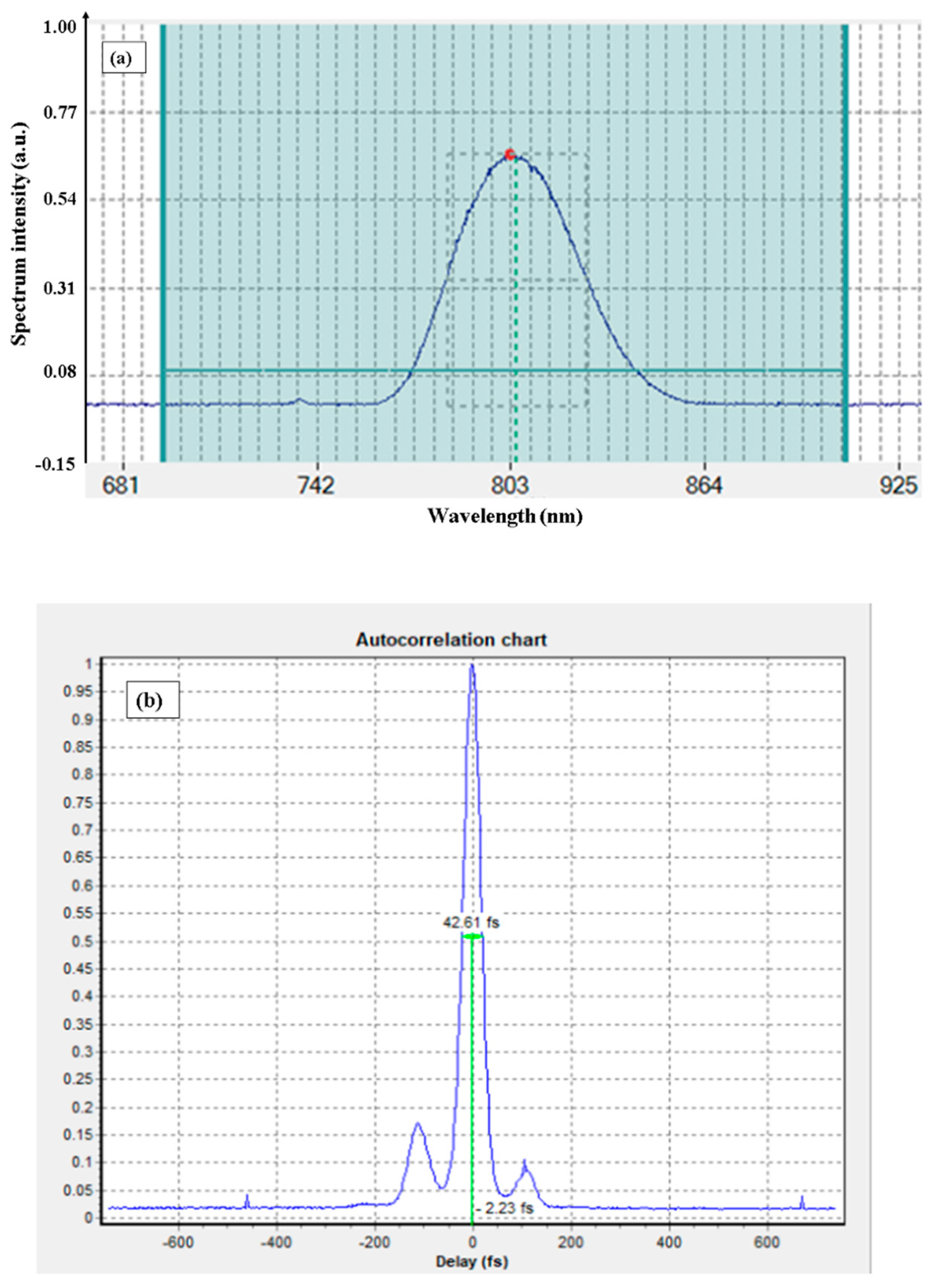
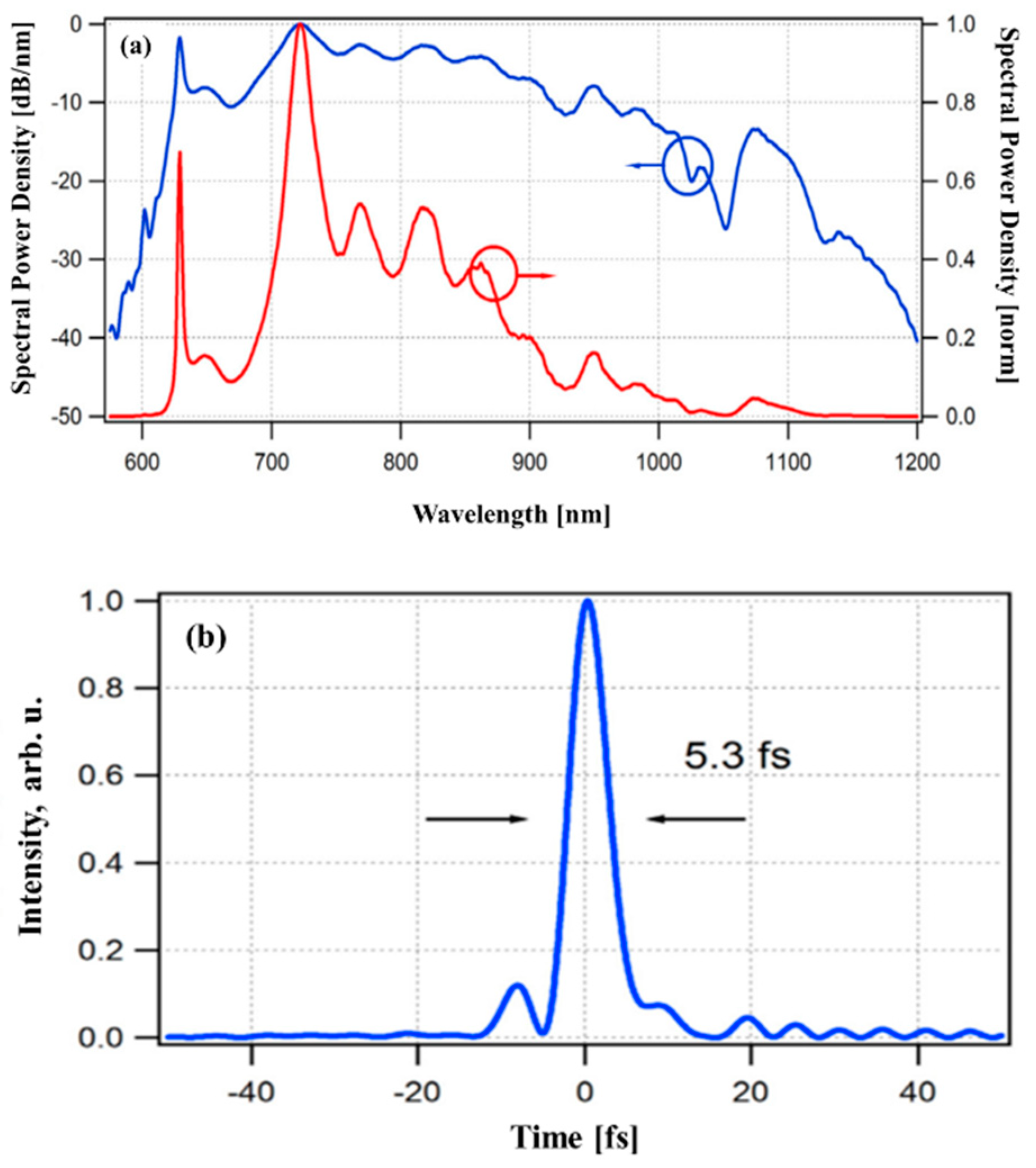
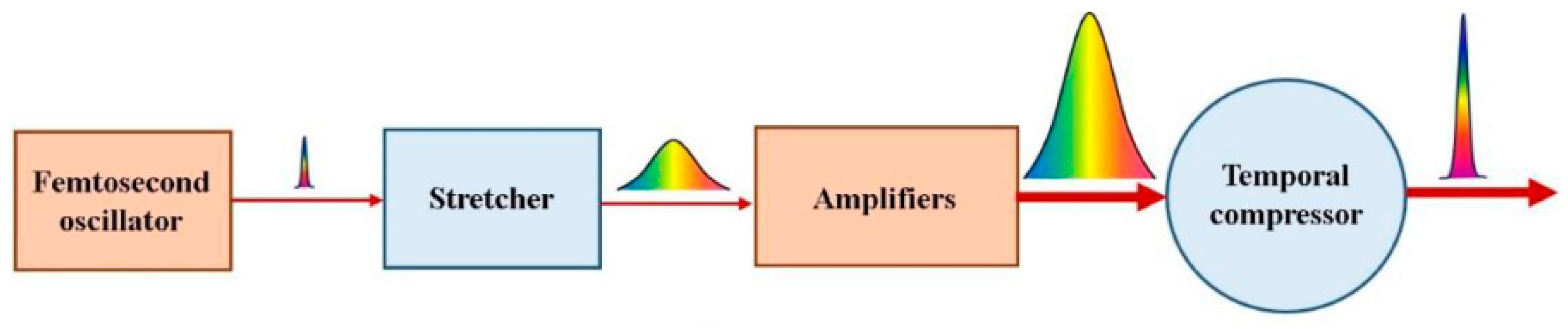
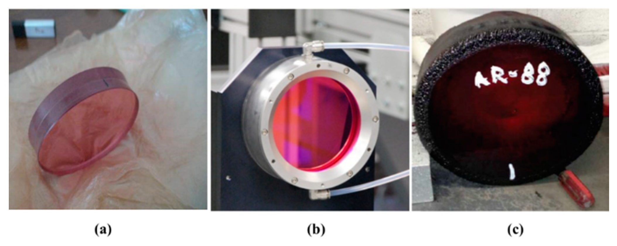
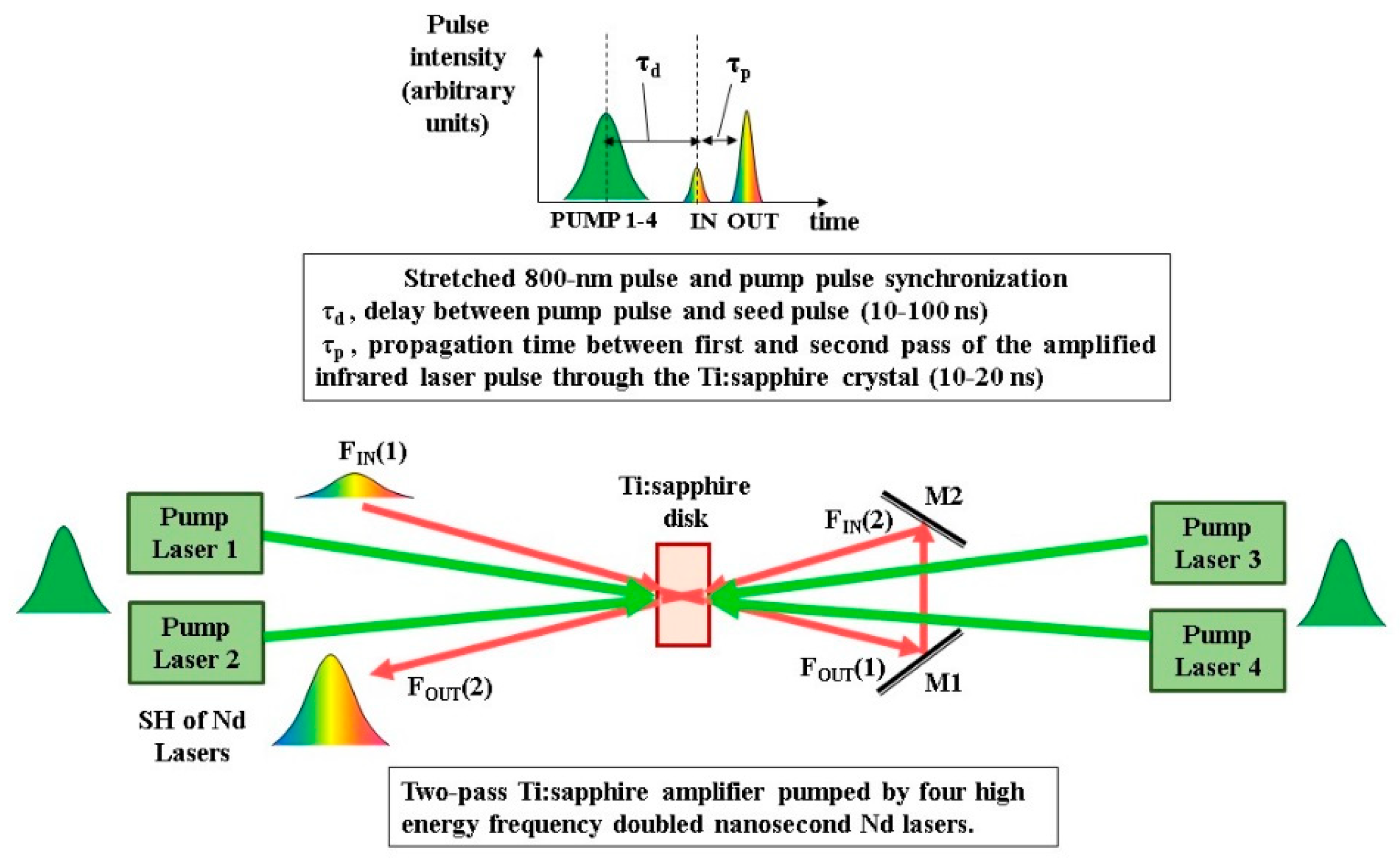
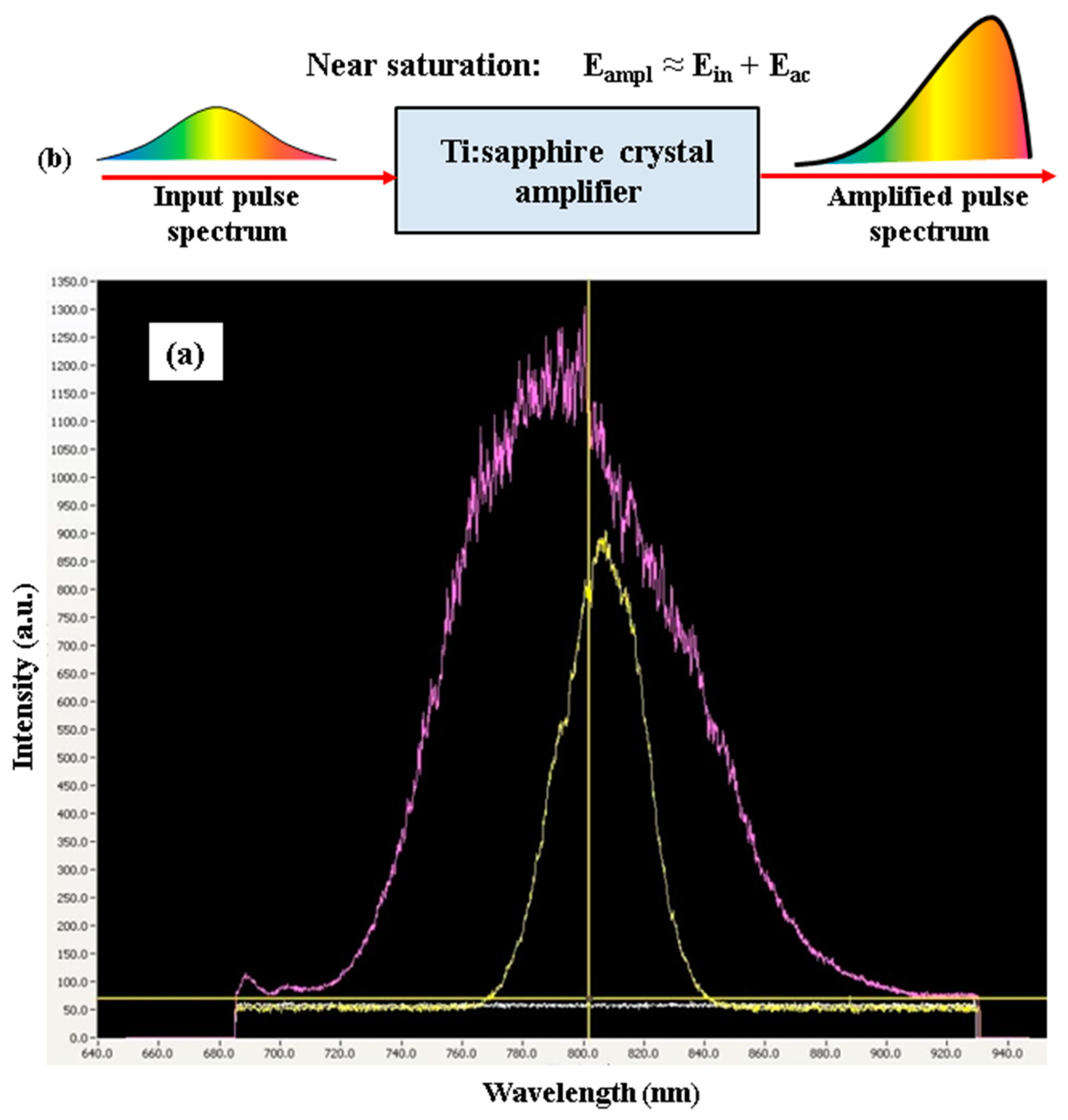
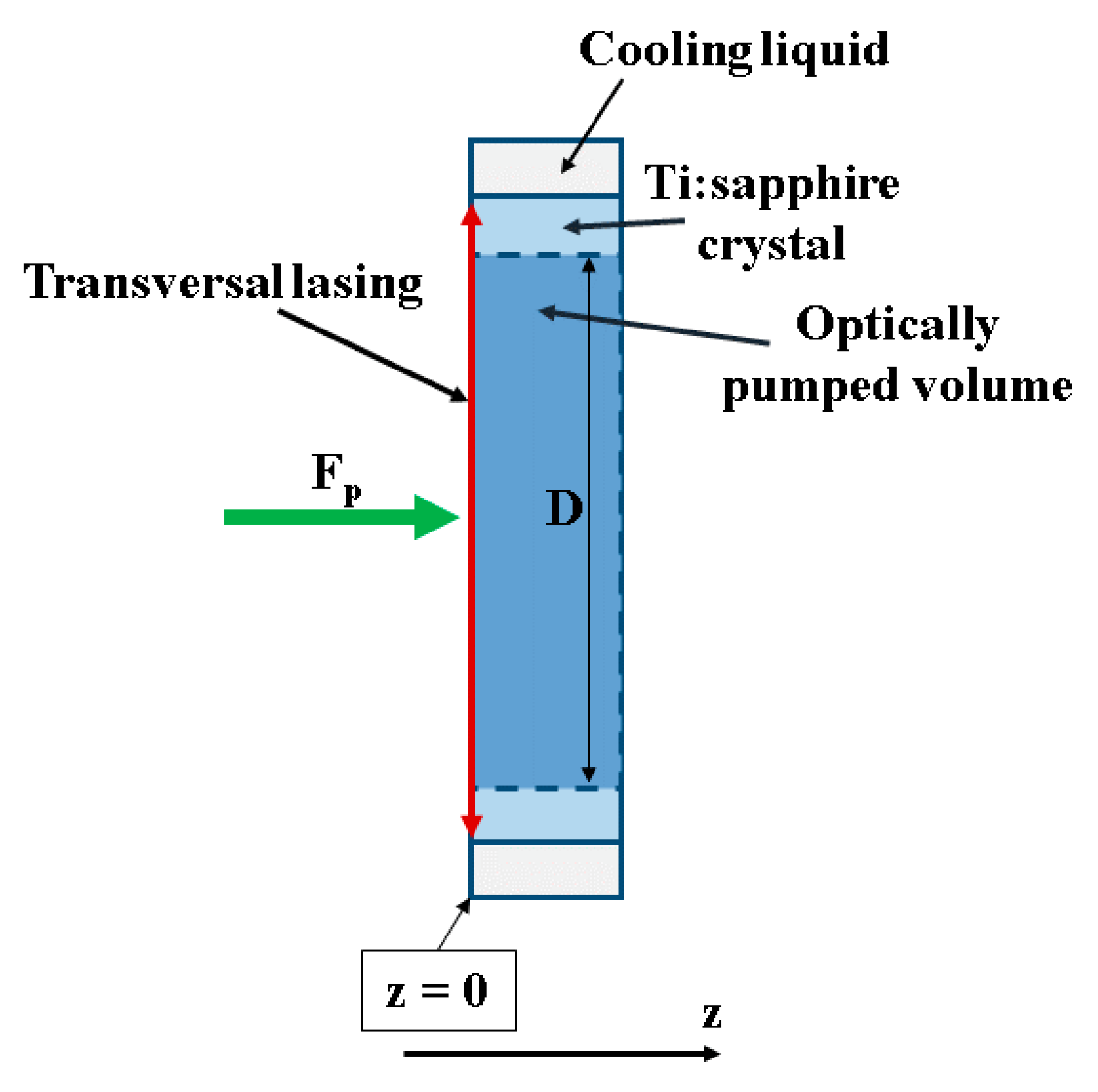
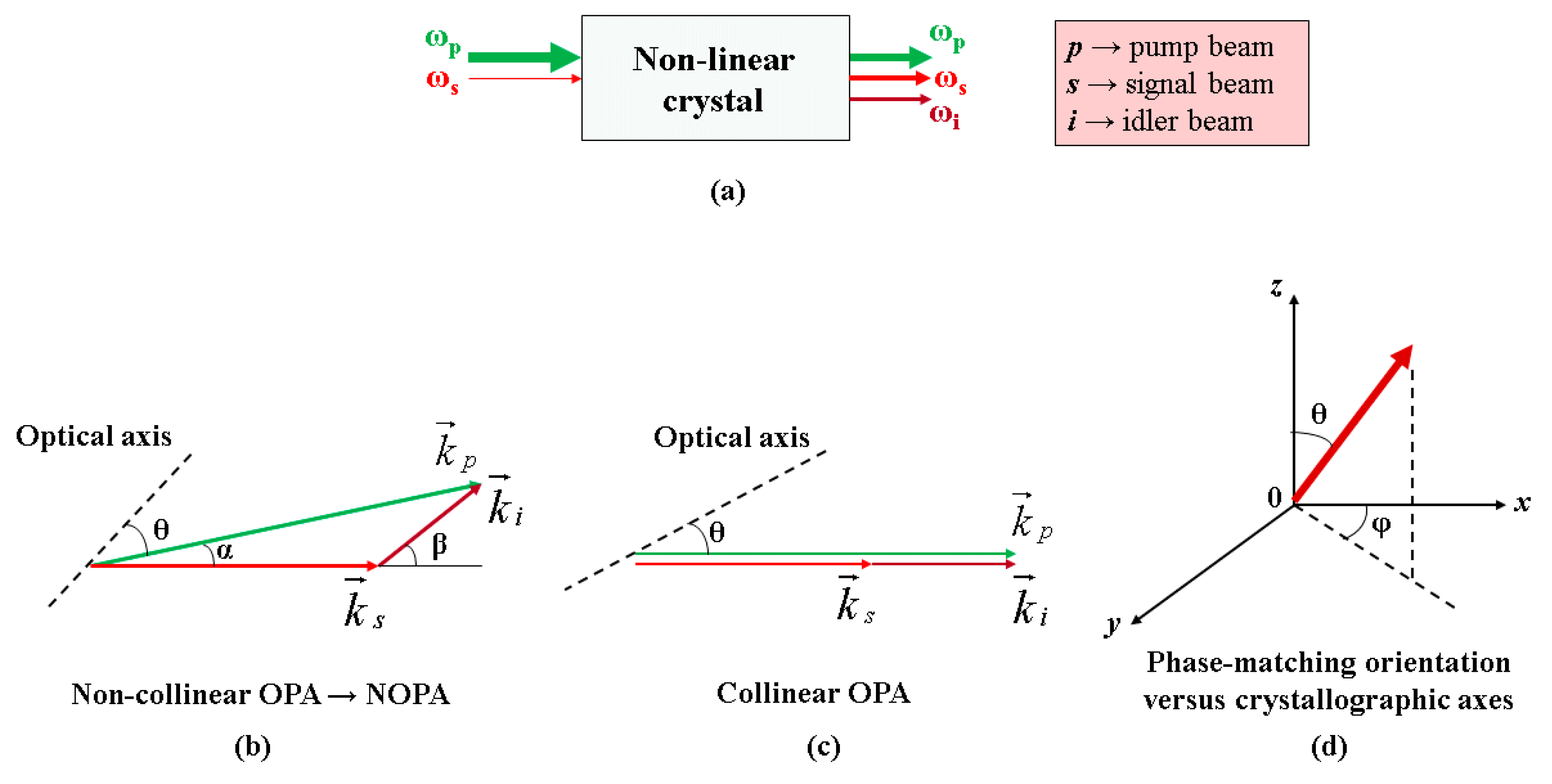
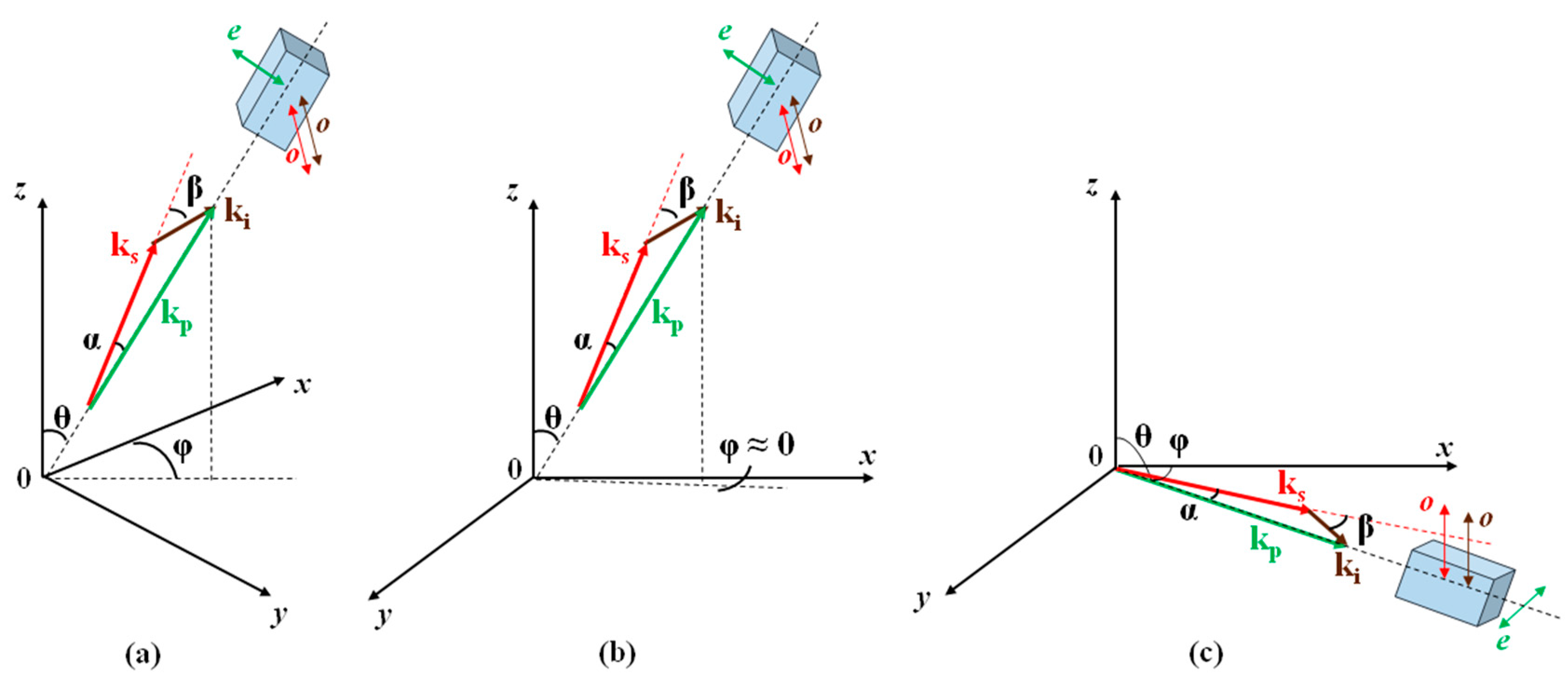
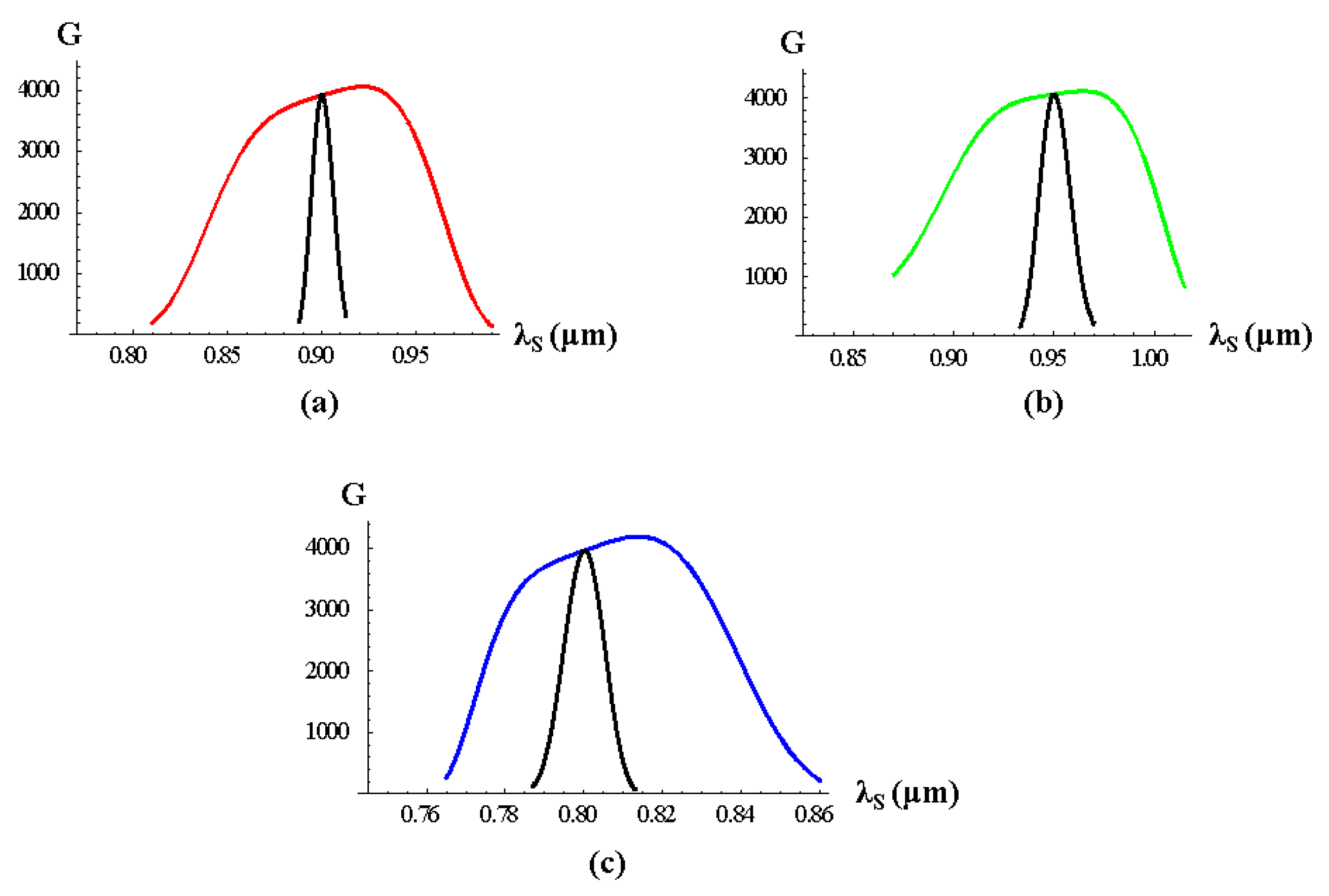
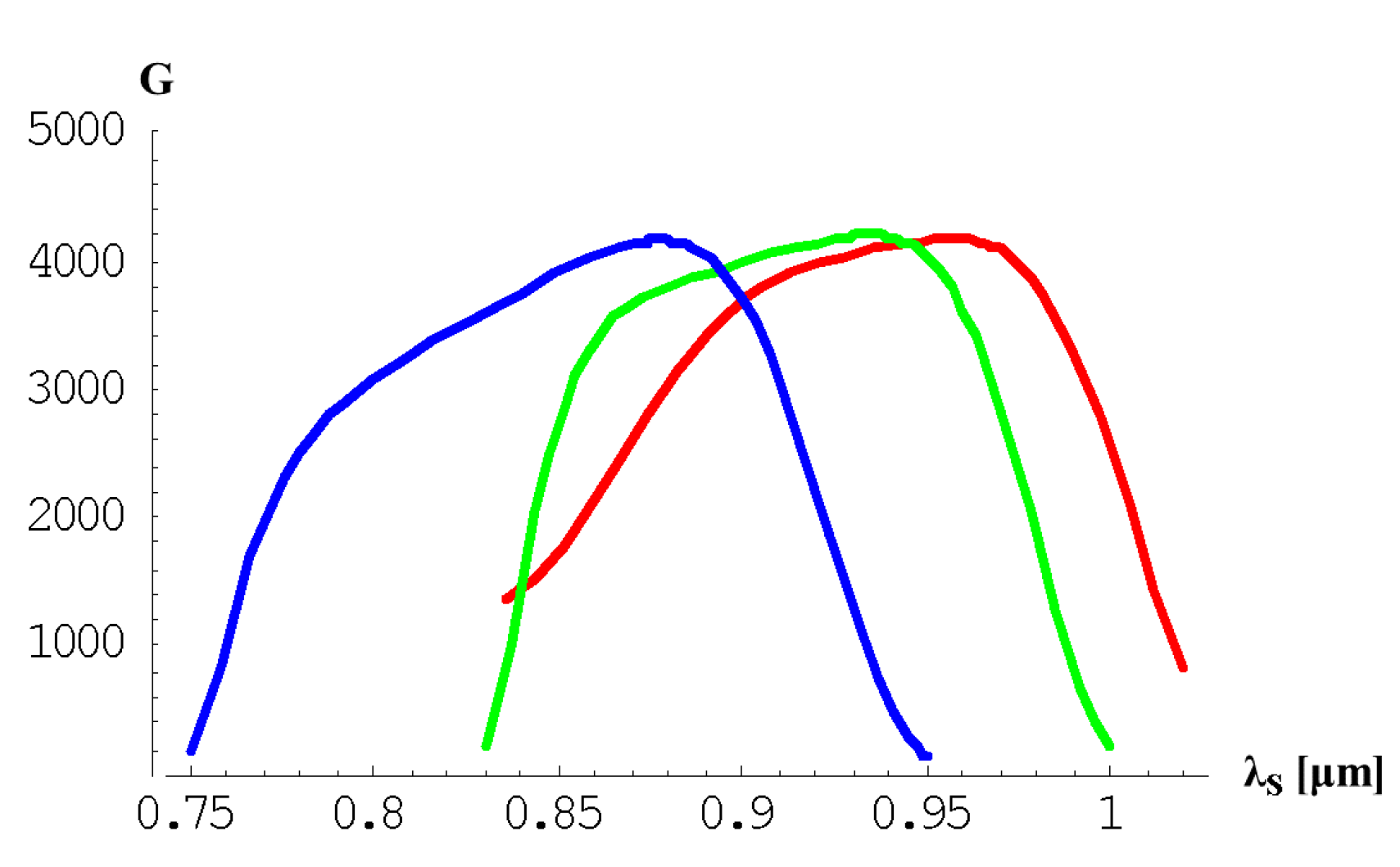
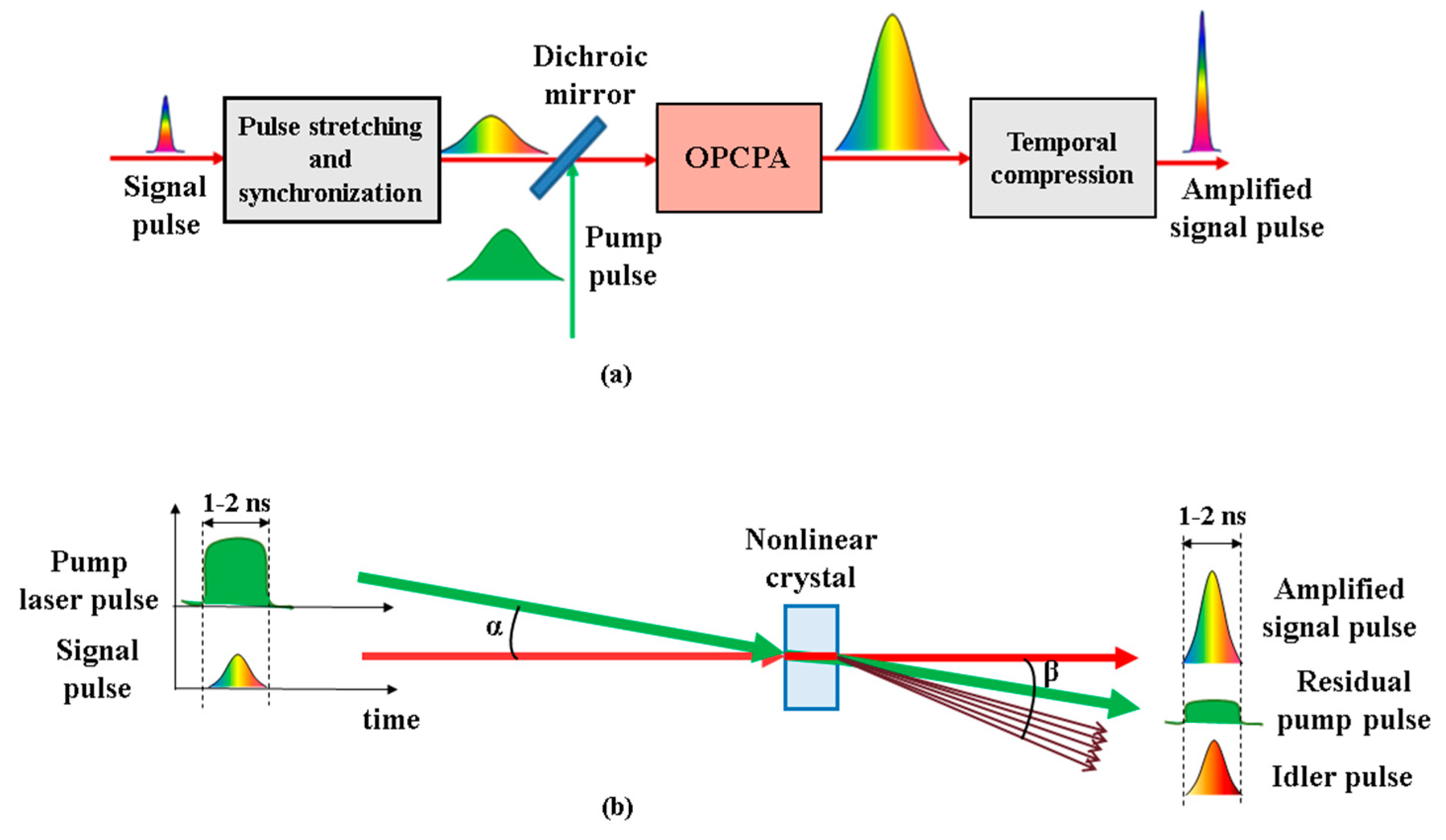
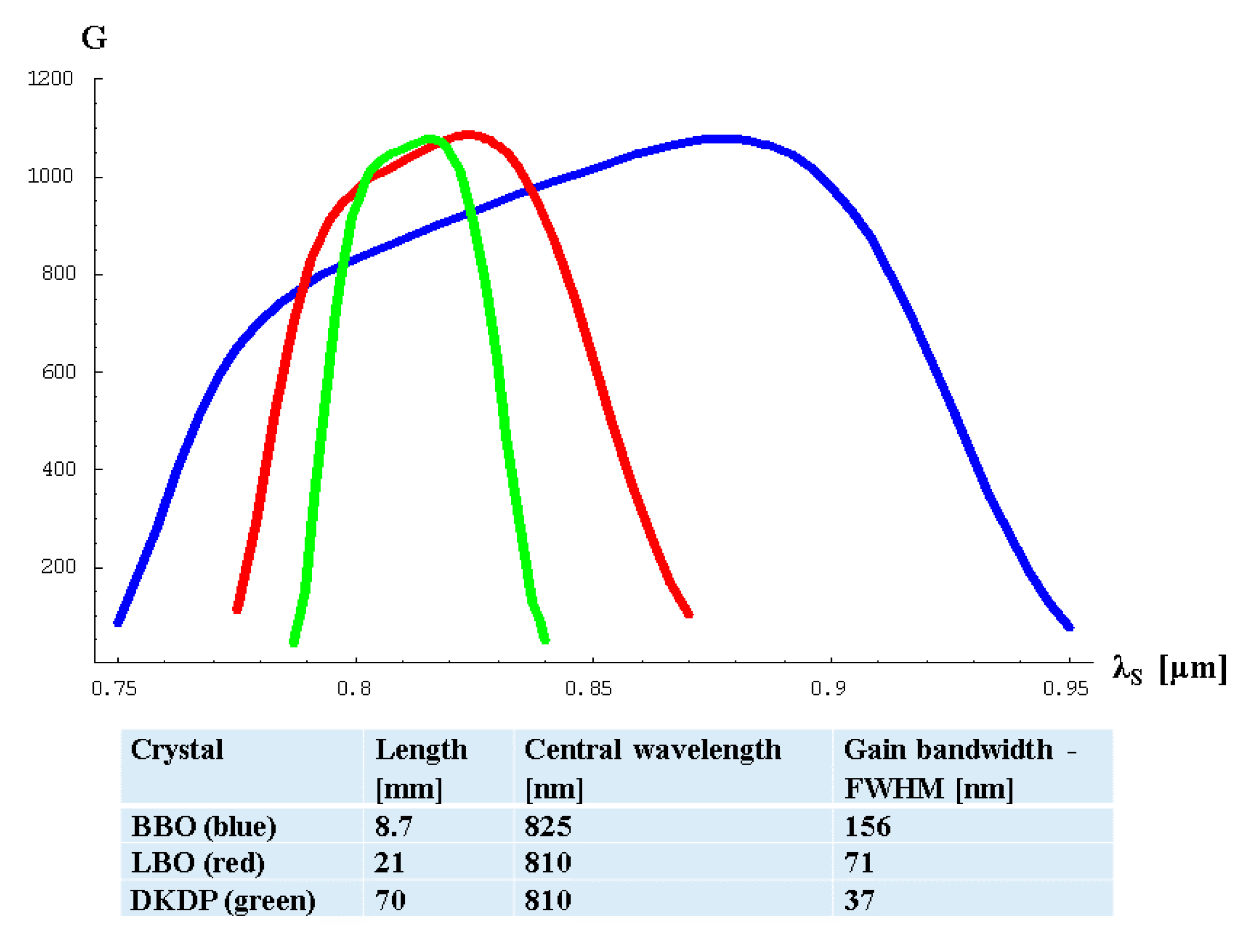
Table 1.
Spectroscopic properties of laser crystals.
| Ti:sapphire (Ti:Al2O3) | Cr:LiSAF (Cr:LiSrAlF6) | Cr:Forsterite (Cr:Mg2SiO4) | |
|---|---|---|---|
| Emission peak (nm) | 790 | 850 | 1240 |
| Gain bandwidth (nm) | >200 | >150 | >150 |
| Upper laser level lifetime (μs) | 3.2 | 67 | 2.7 |
| Nonlinear index n2 (× 10−16 cm2/W) | 5 | 1.5 | 2 |
| Optical pump wavelength (nm) | 488–532 nm | 640–690 nm | 1064 nm |
Table 2.
The properties of Ti3+:sapphire crystals.
| Property | Value |
|---|---|
| Chemical formula | Ti3+:Al2O3 |
| Crystal structure | hexagonal |
| Mass density | 3.98 g/cm3 |
| Thermal conductivity (at 300 K) | 33 W m−1 K−1 |
| Thermal expansion coefficient | 5 × 10⁻⁶ K−1 |
| Temperature dependence of refractive index | 13 × 10−6 K−1 |
| Refractive index at 800 nm | 1.76 |
| Birefringence | Negative uniaxial |
| Fluorescence lifetime | 3.2 μs |
| Peak emission cross section (at 790 nm, polarization parallel to the c axis) | 4.1 × 10⁻¹⁹ cm2 |
Table 3.
The advantages and drawbacks of the large bandwidth laser pulses amplification in Ti:sapphire crystals.
Table 3.
The advantages and drawbacks of the large bandwidth laser pulses amplification in Ti:sapphire crystals.
| Advantages | Drawbacks |
|---|---|
| • Noncritical pump pulse duration, acceptable in the range of 10–100 ns. • Non-critical signal-pump pulse synchronization time, in the range of 10 ns. • Non-critical seed-pump beams geometry configuration. • For high-energy Ti:sapphire amplifiers, high-energy green pump lasers, with ~10–20 ns pulse duration, are commercially available. | • Spectral band narrowing in high order of magnitude amplification regenerative amplifiers and red shifting in the near saturation operated multi-pass amplifiers provide longer recompressed amplified pulse. • Due to the amplified spontaneous emission, the intensity contrast of amplified femtosecond pulses decreases. • Thermal loading of the laser amplifying crystals generates thermal lenses, wavefront distortions, phase dispersion, and bad laser beam focusing. • Parasitic lasing limits the pump energy in large aperture Ti:sapphire crystal amplifiers. |
Table 4.
The calculated main parameters of the BB-NOPA and narrow-band collinear OPA.
| Crystal | Parametric Process | λp (nm) | λsc (nm) | λi (nm) | deff (pm/V) | θ (deg) | ϕ (deg) | α (deg) | Gain Bandwidth FWHM (nm) |
|---|---|---|---|---|---|---|---|---|---|
| BBO | BB-NOPA | 532 | 900 | 1301 | 2.07 | 23.7 | 0 | 2.26 | 120 |
| BBO | Collinear OPA | 532 | 900 | 1301 | 2.07 | 22.6 | 0 | 0 | 13 |
| DKDP | BB-NOPA | 527 | 950 | 1184 | 0.22 | 37.0 | 45 | 0.85 | 110 |
| DKDP | Collinear OPA | 527 | 950 | 1184 | 0.22 | 36.7 | 45 | 0 | 15 |
| LBO | BB-NOPA | 532 | 800 | 1588 | 0.83 | 90 | 12.6 | 1.11 | 70 |
| LBO | Collinear OPA | 532 | 800 | 1588 | 0.83 | 90 | 9.4 | 0 | 12 |
Table 5.
UBB NOPA phase-matching parameters in non-linear crystals.
| Crystal | λp (nm) | λsc (nm) | λi (nm) | deff (pm/V) | θ (deg) | φ (deg) | α (deg) | L (mm) | Gain Bandwidth FWHM (nm) |
|---|---|---|---|---|---|---|---|---|---|
| BBO | 532 | 825 | 1497 | 2.07 | 23.8 | 0 | 2.41 | 9.9 | 150 |
| DKDP | 527 | 900 | 1271 | 0.22 | 37.0 | 45 | 0.92 | 77.0 | 135 |
| LBO | 532 | 934 | 1235 | 0.83 | 90 | 13.5 | 1.26 | 24.4 | 140 |
Table 6.
The advantages and drawbacks of OPCPA in large size nonlinear crystals.
| Advantages | Drawbacks |
|---|---|
| • Free from spectral band narrowing and red shifting. Large spectral bandwidth can be preserved during amplification process • Signal pulse is amplified only when signal and pump pulses are temporally and spatially overlapped in the nonlinear crystal. Intensity contrast is improved outside the signal and pump pulses overlapping time window • No thermal loading of nonlinear crystals Low amplified pulse beam wavefront distortions | • Critical signal-pump pulse synchronization and spatial overlapping. Optical synchronization of signal and pump laser pulses is necessary in case of femtosecond-picosecond pulses parametric amplification. Critical angle between signal and pump wave vectors. • Technical difficulties are related to the pump lasers development. High energy single beam pump lasers with useful pump energy is in the range of 1–3 ns pulse duration are required Low repetition rate of kJ-energy pump lasers causes the development of single-shot multi-PW laser systems • Critical spatial and temporal pump laser beam profiles. Amplified laser pulse spectrum strongly depends on pump pulse fluctuations Very stable spatial and temporal profiles of the pump laser pulses are required |
© 2019 by the author. Licensee MDPI, Basel, Switzerland. This article is an open access article distributed under the terms and conditions of the Creative Commons Attribution (CC BY) license (http://creativecommons.org/licenses/by/4.0/).
Share and Cite
MDPI and ACS Style
Dabu, R. Femtosecond Laser Pulses Amplification in Crystals. Crystals 2019, 9, 347. https://0-doi-org.brum.beds.ac.uk/10.3390/cryst9070347
AMA Style
Dabu R. Femtosecond Laser Pulses Amplification in Crystals. Crystals. 2019; 9(7):347. https://0-doi-org.brum.beds.ac.uk/10.3390/cryst9070347
Chicago/Turabian StyleDabu, Razvan. 2019. "Femtosecond Laser Pulses Amplification in Crystals" Crystals 9, no. 7: 347. https://0-doi-org.brum.beds.ac.uk/10.3390/cryst9070347
Note that from the first issue of 2016, this journal uses article numbers instead of page numbers. See further details here.